3G TS 25.427 V3.3 - qtc.jp · PDF fileUTRAN Iub/Iur Interface User Plane Protocol ... 6.3.2...
29
3G TS 25.427 V3.3.0 (2000-06) Technical Specification 3rd Generation Partnership Project; Technical Specification Group Radio Access Network; UTRAN Iub/Iur Interface User Plane Protocol for DCH Data Streams (Release 1999) The present document has been developed within the 3 rd Generation Partnership Project (3GPP TM ) and may be further elaborated for the purposes o 3GPP. The present document has not been subject to any approval process by the 3GPP Organisational Partners and shall not be implemented. This Specification is provided for future development work within 3GPP only. The Organisational Partners accept no liability for any use of thisSpecification. Specifications and reports for implementation of the 3GPP TM system should be obtained via the 3GPP Organisational Partners' Publications Offices
Transcript of 3G TS 25.427 V3.3 - qtc.jp · PDF fileUTRAN Iub/Iur Interface User Plane Protocol ... 6.3.2...
3G TS 25.427 V3.3.0 (2000-06)Technical Specification
3rd Generation Partnership Project;Technical Specification Group Radio Access Network;
UTRAN Iub/Iur Interface User Plane Protocolfor DCH Data Streams
(Release 1999)
The present document has been developed within the 3rd Generation Partnership Project (3GPP TM) and may be further elaborated for the purposes of 3GPP. The present document has not been subject to any approval process by the 3GPP Organisational Partners and shall not be implemented. This Specification is provided for future development work within 3GPP only. The Organisational Partners accept no liability for any use of thisSpecification. Specifications and reports for implementation of the 3GPP TM system should be obtained via the 3GPP Organisational Partners' Publications Offices.

3GPP
2Release 1999 3G TS 25.427 V3.3.0 (2000-06)
Keywords
3GPP
Postal address
3GPP support office address 650 Route des Lucioles - Sophia Antipolis
Valbonne - FRANCE Tel.: +33 4 92 94 42 00 Fax: +33 4 93 65 47 16
Internet http://www.3gpp.org
Copyright Notification
No part may be reproduced except as authorized by written permission. The copyright and the foregoing restriction extend to reproduction in all media.
© 2000, 3GPP Organizational Partners (ARIB, CWTS, ETSI, T1, TTA,TTC).
All rights reserved.

3GPP
3Release 1999 3G TS 25.427 V3.3.0 (2000-06)
Contents
Foreword ................................................................................................................................................5
1 Scope ............................................................................................................................................6
2 References ....................................................................................................................................6
3 Definitions and abbreviations ...........................................................................................................6 3.1 Definitions............................................................................................................................................................................. 6 3.2 Abbreviations....................................................................................................................................................................... 6
4 General aspects..............................................................................................................................7 4.1 DCH FP services .................................................................................................................................................................. 7 4.2 Services expected from data transport.............................................................................................................................. 7 4.3 Protocol Version................................................................................................................................................................... 7
5 DCH Frame Protocol procedures ....................................................................................................8 5.1 Data transfer ......................................................................................................................................................................... 8 5.1.1 Uplink.............................................................................................................................................................................. 8 5.1.2 Downlink......................................................................................................................................................................... 8 5.2 Timing adjustment ............................................................................................................................................................... 9 5.3 Synchronisation................................................................................................................................................................... 9 5.4 Outer loop PC information transfer [FDD] ..................................................................................................................... 10 5.5 Node Synchronisation ...................................................................................................................................................... 10 5.6 Rx timing deviation measurement [TDD]........................................................................................................................ 11 5.7 DSCH TFCI Signalling [FDD]........................................................................................................................................... 11 5.8 Radio Interface Parameter Update [FDD]....................................................................................................................... 11
6 Frame structure and coding...........................................................................................................12 6.1 General................................................................................................................................................................................. 12 6.1.1 General principles for the coding .............................................................................................................................. 12 6.2 Data frames ......................................................................................................................................................................... 13 6.2.1 Introduction.................................................................................................................................................................. 13 6.2.2 Uplink data frame ......................................................................................................................................................... 13 6.2.3 Downlink data frame.................................................................................................................................................... 15 6.2.4 Coding of information elements in data frames....................................................................................................... 17 6.2.4.1 Header CRC............................................................................................................................................................ 17 6.2.4.2 Frame Type (FT).................................................................................................................................................... 17 6.2.4.3 Connection Frame Number (CFN)....................................................................................................................... 17 6.2.4.4 Transport Format Indicator (TFI)........................................................................................................................ 17 6.2.4.5 Quality Estimate (QE)............................................................................................................................................ 17 6.2.4.6 Transport Block (TB)............................................................................................................................................ 18 6.2.4.7 CRC indicator (CRCI)............................................................................................................................................ 18 6.2.4.8 Payload CRC .......................................................................................................................................................... 18 6.2.4.9 Spare Extension ..................................................................................................................................................... 18 6.3 Control frames .................................................................................................................................................................... 18 6.3.1 Introduction.................................................................................................................................................................. 18 6.3.2 Header structure of the control frames..................................................................................................................... 19 6.3.2.1 Frame CRC.............................................................................................................................................................. 19 6.3.2.2 Frame Type (FT).................................................................................................................................................... 19 6.3.2.3 Control Frame Type .............................................................................................................................................. 19 6.3.3 Payload structure and information elements ........................................................................................................... 20 6.3.3.1 Timing Adjustment ............................................................................................................................................... 20 6.3.3.1.1 Payload structure ............................................................................................................................................ 20 6.3.3.1.2 CFN.................................................................................................................................................................... 20 6.3.3.1.3 Time of arrival (ToA)...................................................................................................................................... 20 6.3.3.1.4 Spare Extension ............................................................................................................................................... 21 6.3.3.2 DL synchronisation .............................................................................................................................................. 21
3GPP
4Release 1999 3G TS 25.427 V3.3.0 (2000-06)
6.3.3.2.1 Payload structure ............................................................................................................................................ 21 6.3.3.2.2 CFN.................................................................................................................................................................... 21 6.3.3.2.3 Spare Extension ............................................................................................................................................... 21 6.3.3.3 UL synchronisation .............................................................................................................................................. 21 6.3.3.3.1 Payload structure ............................................................................................................................................ 21 6.3.3.3.2 CFN.................................................................................................................................................................... 22 6.3.3.3.3 Time of arrival (ToA)...................................................................................................................................... 22 6.3.3.3.4 Spare Extension ............................................................................................................................................... 22 6.3.3.4 UL Outer loop power control [FDD]................................................................................................................... 22 6.3.3.4.1 Payload structure ............................................................................................................................................ 22 6.3.3.4.2 SIR Target......................................................................................................................................................... 22 6.3.3.4.3 Spare Extension ............................................................................................................................................... 22 6.3.3.5 DL Node Synchronisation ................................................................................................................................... 22 6.3.3.5.1 Payload structure ............................................................................................................................................ 22 6.3.3.5.2 T1 ..................................................................................................................................................................... 23 6.3.3.5.3 Spare Extension ............................................................................................................................................... 23 6.3.3.6 UL Node Synchronisation ................................................................................................................................... 23 6.3.3.6.1 Payload structure ............................................................................................................................................ 23 6.3.3.6.2 T1 ..................................................................................................................................................................... 24 6.3.3.6.3 T2 ..................................................................................................................................................................... 24 6.3.3.6.4 T3 ..................................................................................................................................................................... 24 6.3.3.6.5 Spare Extension ............................................................................................................................................... 25 6.3.3.7 Rx Timing Deviation.............................................................................................................................................. 25 6.3.3.7.1 Payload structure ............................................................................................................................................ 25 6.3.3.7.2 Rx Timing Deviation........................................................................................................................................ 25 6.3.3.7.3 Spare Extension ............................................................................................................................................... 25 6.3.3.8 [FDD - DSCH TFCI signalling]............................................................................................................................ 25 6.3.3.8.1 Payload structure ............................................................................................................................................ 25 6.3.3.8.2 TFCI (field 2) .................................................................................................................................................... 26 6.3.3.8.3 Spare Extension ............................................................................................................................................... 26 6.3.3.9 Radio Interface Parameter Update ...................................................................................................................... 26 6.3.3.9.1 Payload structure ............................................................................................................................................ 26 6.3.3.9.2 Radio Interface Parameter Update flags....................................................................................................... 26 6.3.3.9.3 TPC power offset............................................................................................................................................. 27 6.3.3.9.4 Spare Extension ............................................................................................................................................... 27
7 Handling of Unknown, Unforeseen and Erroneous Protocol Data ....................................................27 7.1 General................................................................................................................................................................................. 27 7.2 Error detection.................................................................................................................................................................... 27 7.2.1 CRC Calculation........................................................................................................................................................... 27 7.2.1.1 Relation between input and output of the Cyclic Redundancy Check......................................................... 28
Annex A (informative): Change History ........................................................................................... 29

3GPP
5Release 1999 3G TS 25.427 V3.3.0 (2000-06)
Foreword This Technical Specification (TS) has been produced by the 3rd Generation Partnership Project (3GPP).
The contents of the present document are subject to continuing work within the TSG and may change following formal TSG approval. Should the TSG modify the contents of the present document, it will be re-released by the TSG with an identifying change of release date and an increase in version number as follows:
Version x.y.z
where:
x the first digit:
1 presented to TSG for information;
2 presented to TSG for approval;
3 or greater indicates TSG approved document under change control.
y the second digit is incremented for all changes of substance, i.e. technical enhancements, corrections, updates, etc.
z the third digit is incremented when editorial only changes have been incorporated in the document.
3GPP
6Release 1999 3G TS 25.427 V3.3.0 (2000-06)
1 Scope This document shall provide a description of the UTRAN Iur and Iub interfaces user plane protocols for Dedicated Transport Channel data streams as agreed within the TSG-RAN working group 3.
2 References The following documents contain provisions which, through reference in this text, constitute provisions of the present document.
?? References are either specific (identified by date of publication, edition number, version number, etc.) or non-specific.
?? For a specific reference, subsequent revisions do not apply.
?? For a non-specific reference, the latest version applies.
?? For this Release 1999 document, references to 3G documents are for Release 1999 versions (version 3.x.y).
[1] TS UMTS 25.301: "Radio Interface Protocol Architecture".
[2] TS 25.401: "UTRAN architecture description".
[3] TS 25.302: "Services provided by the Physical Layer, Source WG2".
[4] TS 25.433: "UTRAN Iub interface NBAP signalling".
[5] TS 25.402: "Synchronisation in UTRAN, Stage 2".
[6] TS 25.423: "UTRAN Iur interface RNSAP signalling".
[7] TS 25.215: "Physical layer – Measurements (FDD)".
[8] TS 25.225: "Physical layer – Measurements (TDD)".
[9] TS 25.212: "Multiplexing and channel coding, FDD".
[10] TS 25.222: "Multiplexing and channel coding, TDD".
3 Definitions and abbreviations
3.1 Definitions For the purposes of the present document, the following terms and definitions apply:
Transport Connection: service provided by the transport layer and used by Frame Protocol for the delivery of FP PDU.
3.2 Abbreviations For the purposes of the present document, the following abbreviations apply:
CFN Connection Frame Number CRC Cyclic Redundancy Checksum CRCI CRC Indicator DCH Dedicated Transport Channel DL Downlink

3GPP
7Release 1999 3G TS 25.427 V3.3.0 (2000-06)
DSCH Downlink Shared Channel FP Frame Protocol FT Frame Type PC Power Control QE Quality Estimate TB Transport Block TBS Transport Block Set TFI Transport Format Indicator ToA Time of arrival TTI Transmission Time Interval UL Uplink
4 General aspects The specification of Iub DCH data streams is also valid for Iur DCH data streams.
The SRNC is responsible for creating communications inside the SRNS. The SRNC provides to the Node B the complete configuration of the Transport channels to be provided by the Node B for a given communication.
The parameters of a Transport channel are described in [1]. These Transport channels are multiplexed on the downlink by the Node B on radio physical channels, and de-multiplexed on the uplink from radio physical channels to Transport channels.
Every set of coordinated Transport channel related to one UE context that is communicated over a set of cells that are macro-diversity combined within Node B or DRNC, is carried on one transport connection. This means that there are as many transport connections as set of coordinated Transport channels and User ports for that communication.
Bi-directional transport connections are used.
4.1 DCH FP services DCH frame protocol provides the following services:
- Transport of TBS across Iub and Iur interface.
- Transport of outer loop power control information between the SRNC and the Node B.
- Support of transport channel synchronisation mechanism.
- Support of Node Synchronisation mechanism.
- Transfer of DSCH TFI from SRNC to Node B.
- Transfer of Rx timing deviation (TDD) from the Node B to the SRNC.
4.2 Services expected from data transport Following service is required from the transport layer:
- In sequence delivery of FP PDU.
4.3 Protocol Version This revision of the specification specifies version 1 of the protocol.

3GPP
8Release 1999 3G TS 25.427 V3.3.0 (2000-06)
5 DCH Frame Protocol procedures
5.1 Data transfer When there is some data to be transmitted, DCH data frames are transferred every transmission time interval between the SRNC and the Node B for downlink transfer, and between Node B and SRNC for uplink transfer.
An optional error detection mechanism may be used to protect the data transfer if needed. At the transport channel setup it shall be specified if the error detection on the user data is used.
5.1.1 Uplink
SRNCNB
Data Frame
Figure 1: Uplink data transfer
Two modes can be used for the UL transmission: normal mode and silent mode. The mode is selected by the SRNC when the transport connection is setup and signaled to the Node B with the relevant control plane procedure.
- In normal mode, the Node B shall always send an UL data frame to the RNC for all the DCHs in a set of coordinated DCHs regardless of the number of Transport Blocks of the DCHs.
- In silent mode and in case only one transport channel is transported on a transport bearer, the node-B shall not send an UL data frame to the RNC when it has received a TFI indicating “number of TB equal to 0” for the transport channel during a TTI.
In silent mode and in case of coordinated DCHs, when the Node B receives a TFI indicating “number of TB equal to 0” for all the DCHs in a set of coordinated DCHs, the Node B shall not send an UL data frame to the RNC for this set of coordinated DCHs.
When UL synchronisation is lost or not yet achieved on the Uu, UL data frames are not sent to the SRNC.
When Node B receives an invalid TFCI no data frame shall be sent to the SRNC.
5.1.2 Downlink
SRNC
Data Frame
NB
Figure 2: Downlink data transfer
The Node B shall only consider a transport connection synchronised after it has received at least one data frame on this transport connection with a positive TOA [4].
The Node B shall consider the DL user plane for a certain RL synchronised if all transport connections established for carrying DL data frames for this RL can be considered synchronised.
3GPP
9Release 1999 3G TS 25.427 V3.3.0 (2000-06)
Only when the DL user plane is considered synchronised, the Node B shall transmit on the [FDD - DL DPDCH][TDD – DPCH].
When the DL user plane is considered synchronised and the Node B does not receive a valid FP frame in a TTI, it assumes that there is no data to be transmitted in that TTI for this transport channel.
If the node B is aware of a TFI value corresponding to zero bits for this transport channel, this TFI is assumed. If the TFS contains both a TFI corresponding to “TB length equal to 0 bits” and a TFI corresponding to “number of TB equal to 0”, the node-B shall assume the TFI corresponding to “number of TB equal to 0”.When combining the TFI’s of the different transport channels, a valid TFCI might result and in this case data shall be transmitted on Uu.
If the node B is not aware of a TFI value corresponding to zero bits for this transport channel or if combining the TFI corresponding to zero bits with other TFI’s, results in an unknown TFI combination, the handling as described in the following paragraph shall be applied.
At each frame, the Node B shall build the TFCI value of each CCTrCH, according to the TFI of the DCH data frames multiplexed on this CCTrCH and scheduled for that frame. [FDD - In case the Node receives an unknown combination of DCH data frames, it shall transmit only the DPCCH without TFCI bits.] [TDD - In case the Node receives an unknown combination of DCH data frames, it shall apply DTX, i.e. suspend transmission on the corresponding DPCHs.]
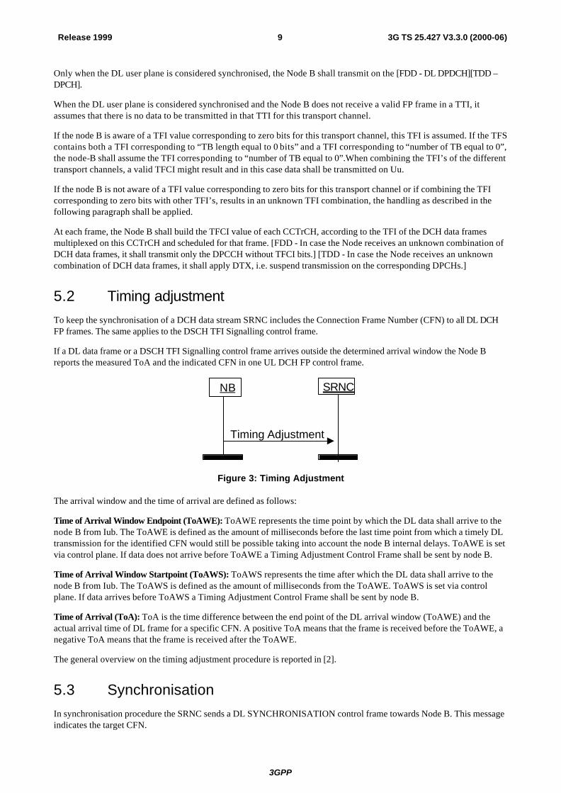
5.2 Timing adjustment To keep the synchronisation of a DCH data stream SRNC includes the Connection Frame Number (CFN) to all DL DCH FP frames. The same applies to the DSCH TFI Signalling control frame.
If a DL data frame or a DSCH TFI Signalling control frame arrives outside the determined arrival window the Node B reports the measured ToA and the indicated CFN in one UL DCH FP control frame.
SRNCNB
Timing Adjustment
Figure 3: Timing Adjustment
The arrival window and the time of arrival are defined as follows:
Time of Arrival Window Endpoint (ToAWE): ToAWE represents the time point by which the DL data shall arrive to the node B from Iub. The ToAWE is defined as the amount of milliseconds before the last time point from which a timely DL transmission for the identified CFN would still be possible taking into account the node B internal delays. ToAWE is set via control plane. If data does not arrive before ToAWE a Timing Adjustment Control Frame shall be sent by node B.
Time of Arrival Window Startpoint (ToAWS): ToAWS represents the time after which the DL data shall arrive to the node B from Iub. The ToAWS is defined as the amount of milliseconds from the ToAWE. ToAWS is set via control plane. If data arrives before ToAWS a Timing Adjustment Control Frame shall be sent by node B.
Time of Arrival (ToA): ToA is the time difference between the end point of the DL arrival window (ToAWE) and the actual arrival time of DL frame for a specific CFN. A positive ToA means that the frame is received before the ToAWE, a negative ToA means that the frame is received after the ToAWE.
The general overview on the timing adjustment procedure is reported in [2].
5.3 Synchronisation In synchronisation procedure the SRNC sends a DL SYNCHRONISATION control frame towards Node B. This message indicates the target CFN.

3GPP
10Release 1999 3G TS 25.427 V3.3.0 (2000-06)
Upon reception of the DL SYNCHRONISATION control frame, Node B shall immediately respond with UL SYNCHRONISATION control frame indicating the ToA for the DL synchronisation frame and the CFN indicated in the received DL SYNCHRONISATION message.
UL SYNCHRONISATION control frame shall always be sent, even if the DL SYNCHRONISATION control frame is received by the Node B within the arrival window.
Synchronisation control frames are also used as keep alive frames, in order to maintain activity on the Iur/Iub transport bearer.
SRNC
DL Synchronisation
NB
UL Synchronisation
Figure 4: DCH Synchronisation procedure
5.4 Outer loop PC information transfer [FDD] Based, for example, on the CRCI values and on the quality estimate in the UL frames, SRNC modifies the SIR target used by the UL Inner Loop Power Control by including the absolute value of the new SIR target in one control frame sent to the Node B's. This control frame can be sent via any of the transport connections dedicated to one UE.
SRNC
Outer loop PC
NB
Figure 5: Outer loop power control information transfer
5.5 Node Synchronisation In the Node Synchronisation procedure, the SRNC sends a DL Node Synchronisation control frame to Node B containing the parameter T1. Upon reception of a DL Node Synchronisation control frame, the Node B shall respond with UL Node Synchronisation Control Frame, indicating t2 and t3, as well as t1 which was indicated in the initiating DL Node Synchronisation control frame.
The t1, t2, t3 parameters are defined as:
T1: RNC specific frame number (RFN) that indicates the time when RNC sends the frame through the SAP to the transport layer.
T2: Node B specific frame number (BFN) that indicates the time when Node B receives the correspondent DL synchronisation frame through the SAP from the transport layer.
T3: Node B specific frame number (BFN) that indicates the time when Node B sends the frame through the SAP to the transport layer.
The general overview on the Node Synchronisation procedure is reported in [2].

3GPP
11Release 1999 3G TS 25.427 V3.3.0 (2000-06)
SRNC
DL Node Synchronization
NB
UL Node Synchronization
Figure 6: Node Synchronisation procedure
5.6 Rx timing deviation measurement [TDD] This procedure is applicable in TDD mode only.
The Node B shall, for all UEs using DCHs, monitor the receive timing of the uplink DPCH bursts arriving over the radio interface, and shall calculate the Rx Timing Deviation. If the calculated value, after rounding, is not zero, it shall be reported to the SRNC in a DCH Control Frame belonging to that UE. For limitation of the frequency of this reporting, the Node B shall not send more than one Rx Timing Deviation value per UE in a DCH Control Frame within one radio frame.
SRNCNB
Rx timing deviation
Figure 7: Rx timing deviation
5.7 DSCH TFCI Signalling [FDD] This procedure is used in order to signal to the node B the TFCI (field 2) . This allows the node B to build the TFCI word(s) which have to be transmitted on the DPCCH.
The procedure consists in sending the DSCH TFCI signalling control frame from the SRNC to the node B. The frame contains the TFCI(field 2) and the correspondent CFN. The DSCH TFCI signalling frame is sent once every Uu frame interval (10 ms) for as long as there is DSCH data for that UE to be transmitted in the associated PDSCH Uu frame. In the event that the node B does not receive a DSCH TFCI signalling control frame then the node B shall infer that no DSCH data is to be transmitted to the UE on the associated PDSCH Uu frame and will build the TFCI word(s) accordingly.
SRNC
DSCH TFCI Signalling
NB
Figure 8: DSCH TFCI Signalling
5.8 Radio Interface Parameter Update [FDD] This procedure is used to update radio interface parameters which are applicable to all RL’s for the concerning UE. Both synchronised and unsynchronised parameter updates are supported.
The procedure consists of a Radio Interface Parameter Update control frame sent by the SRNC to the Node B.

3GPP
12Release 1999 3G TS 25.427 V3.3.0 (2000-06)
SRNC
Radio InterfaceParameter Update
NB
Figure 9: Radio Interface Parameter Update
If the Radio Interface Parameter Update control frame contains a TPC Power Offset value, the Node B shall apply the newly provided TPC PO as soon as possible in case no CFN is included or from the indicated CFN.
6 Frame structure and coding
6.1 General The general structure of a DCH FP frame consists of a header and a payload. The structure is depicted in figure 9A below:
Header Payload
Figure 9A: General structure of a frame protocol PDU
The header contains a CRC checksum, the frame type field and information related to the frame type.
There are two types of DCH FP frames (indicated by the Frame type field):
- DCH data frame.
- DCH control frame.
The payload of the data frames contains radio interface user data, quality information for the transport blocks and for the radio interface physical channel during the transmission time interval (for UL only), and an optional CRC field.
The payload of the control frames contains commands and measurement reports related to transport bearer and the radio interface physical channel but not directly related to specific radio interface user data.
6.1.1 General principles for the coding
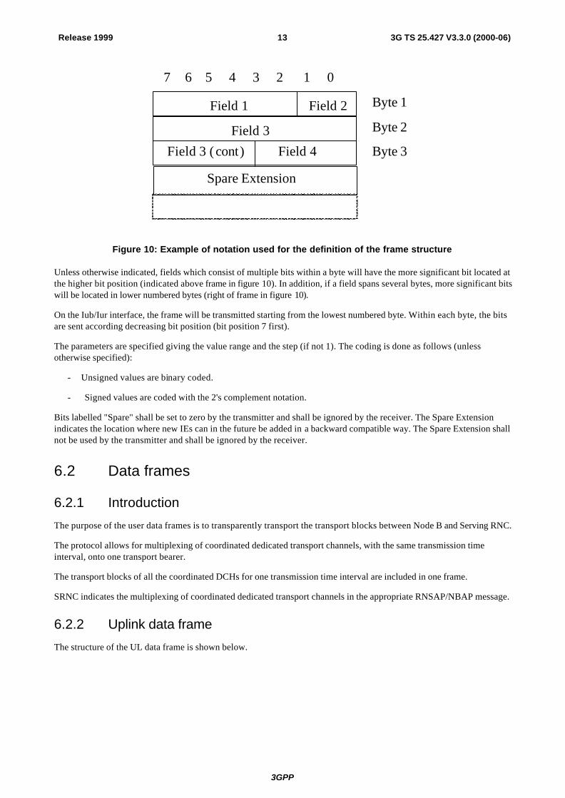
In this specification the structure of frames will be specified by using pictures similar to figure 10.
3GPP
13Release 1999 3G TS 25.427 V3.3.0 (2000-06)
7 6 5 4 3 2 1 0
Field 2
Field 3Field 3 ( cont)
Field 1
Field 4
Byte 1
Byte 2
Byte 3
Spare Extension
Figure 10: Example of notation used for the definition of the frame structure
Unless otherwise indicated, fields which consist of multiple bits within a byte will have the more significant bit located at the higher bit position (indicated above frame in figure 10). In addition, if a field spans several bytes, more significant bits will be located in lower numbered bytes (right of frame in figure 10).
On the Iub/Iur interface, the frame will be transmitted starting from the lowest numbered byte. Within each byte, the bits are sent according decreasing bit position (bit position 7 first).
The parameters are specified giving the value range and the step (if not 1). The coding is done as follows (unless otherwise specified):
- Unsigned values are binary coded.
- Signed values are coded with the 2's complement notation.
Bits labelled "Spare" shall be set to zero by the transmitter and shall be ignored by the receiver. The Spare Extension indicates the location where new IEs can in the future be added in a backward compatible way. The Spare Extension shall not be used by the transmitter and shall be ignored by the receiver.
6.2 Data frames
6.2.1 Introduction
The purpose of the user data frames is to transparently transport the transport blocks between Node B and Serving RNC.
The protocol allows for multiplexing of coordinated dedicated transport channels, with the same transmission time interval, onto one transport bearer.
The transport blocks of all the coordinated DCHs for one transmission time interval are included in one frame.
SRNC indicates the multiplexing of coordinated dedicated transport channels in the appropriate RNSAP/NBAP message.
6.2.2 Uplink data frame
The structure of the UL data frame is shown below.
3GPP
14Release 1999 3G TS 25.427 V3.3.0 (2000-06)
FTHeader CRC
TFI of first DCH
TFI of last DCH
QE
First TB of first DCH
First TB of first DCH (cont.) Pad
Last TB of last DCH (cont.) Pad
Last TB of last DCH
Payload Checksum
Header
Payload
Optional
7 0
CRCI offirst TB offirst DCH
PadCRCI oflastTB oflast DCH
Last TB of first DCH
Last TB of first DCH (cont.) Pad
First TB of last DCH
First TB of last DCH (cont.) Pad
Payload Checksum (cont)
CFN
Spare Extension
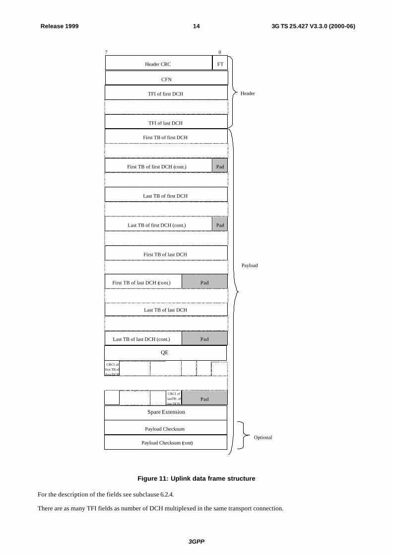
Figure 11: Uplink data frame structure
For the description of the fields see subclause 6.2.4.
There are as many TFI fields as number of DCH multiplexed in the same transport connection.

3GPP
15Release 1999 3G TS 25.427 V3.3.0 (2000-06)
The DCHs in the frame structure are ordered from the lower DCH id ('first DCH') to the higher DCH id ('last DCH').
The size and the number of TBs for each DCH is defined by the correspondent TFI.
If the TB does not fill an integer number of bytes, then bit padding is used as shown in the figure in order to have the octet aligned structure (ex: a TB of 21 bits requires 3 bits of padding).
There is a CRCI for each TB included in the frame. If the CRC indicators of one data frame do not fill an integer number of bytes, then bit padding is used as shown in the figure in order to have the octet aligned structure.
The payload CRC is optional, i.e. the whole 2 bytes field may or may not be present in the frame structure (this is defined at the setup of the transport connection).
6.2.3 Downlink data frame
The structure of the DL data frame is shown below.

3GPP
16Release 1999 3G TS 25.427 V3.3.0 (2000-06)
First TB of first DCH
FTHeader CRC
TFI of first DCH
TFI of last DCH
First TB of first DCH (cont.) Pad
Last TB of last DCH (cont.) Pad
Last TB of last DCH
Payload Checksum (cont.)
Header
Payload
Optional
7 0
First TB of last DCH
First TB of last DCH ( cont.) Pad
Payload Checksum
CFN
Last TB of first DCH
Last TB of first DCH (cont.) Pad
Spare Extension
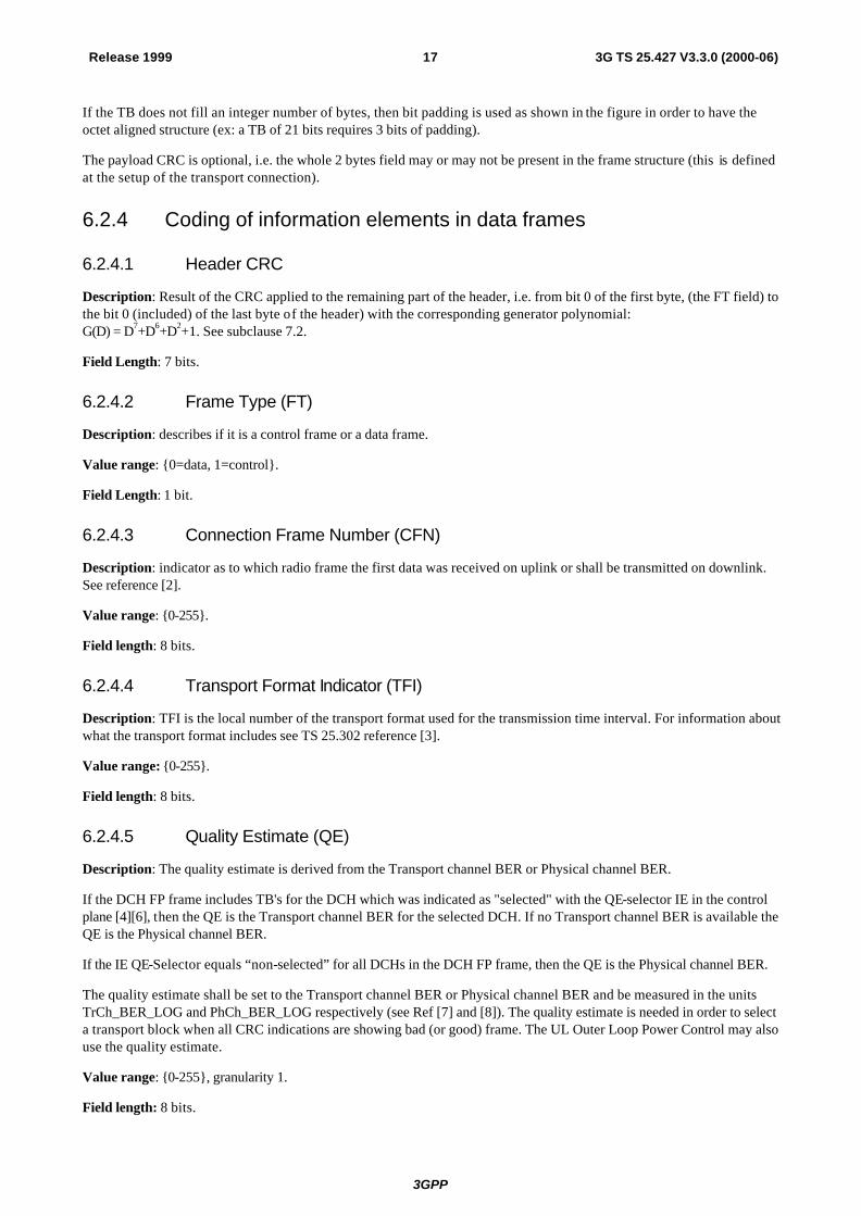
Figure 12: Downlink data frame structure
For the description of the fields see subclause 6.2.4.
There are as many TFI fields as number of DCH multiplexed in the same transport connection.
The DCHs in the frame structure are ordered from the lower DCH id ('first DCH') to the higher DCH id ('last DCH').
The size and the number of TBs for each DCH is defined by the correspondent TFI.
3GPP
17Release 1999 3G TS 25.427 V3.3.0 (2000-06)
If the TB does not fill an integer number of bytes, then bit padding is used as shown in the figure in order to have the octet aligned structure (ex: a TB of 21 bits requires 3 bits of padding).
The payload CRC is optional, i.e. the whole 2 bytes field may or may not be present in the frame structure (this is defined at the setup of the transport connection).
6.2.4 Coding of information elements in data frames
6.2.4.1 Header CRC
Description: Result of the CRC applied to the remaining part of the header, i.e. from bit 0 of the first byte, (the FT field) to the bit 0 (included) of the last byte of the header) with the corresponding generator polynomial: G(D) = D7+D6+D2+1. See subclause 7.2.
Field Length: 7 bits.
6.2.4.2 Frame Type (FT)
Description: describes if it is a control frame or a data frame.
Value range: {0=data, 1=control}.
Field Length: 1 bit.
6.2.4.3 Connection Frame Number (CFN)
Description: indicator as to which radio frame the first data was received on uplink or shall be transmitted on downlink. See reference [2].
Value range: {0-255}.
Field length: 8 bits.
6.2.4.4 Transport Format Indicator (TFI)
Description: TFI is the local number of the transport format used for the transmission time interval. For information about what the transport format includes see TS 25.302 reference [3].
Value range: {0-255}.
Field length: 8 bits.
6.2.4.5 Quality Estimate (QE)
Description: The quality estimate is derived from the Transport channel BER or Physical channel BER.
If the DCH FP frame includes TB's for the DCH which was indicated as "selected" with the QE-selector IE in the control plane [4][6], then the QE is the Transport channel BER for the selected DCH. If no Transport channel BER is available the QE is the Physical channel BER.
If the IE QE-Selector equals “non-selected” for all DCHs in the DCH FP frame, then the QE is the Physical channel BER.
The quality estimate shall be set to the Transport channel BER or Physical channel BER and be measured in the units TrCh_BER_LOG and PhCh_BER_LOG respectively (see Ref [7] and [8]). The quality estimate is needed in order to select a transport block when all CRC indications are showing bad (or good) frame. The UL Outer Loop Power Control may also use the quality estimate.
Value range: {0-255}, granularity 1.
Field length: 8 bits.
3GPP
18Release 1999 3G TS 25.427 V3.3.0 (2000-06)
6.2.4.6 Transport Block (TB)
Description: A block of data to be transmitted or received over the air interface. The transport format indicated by the TFI describes the transport block length and transport block set size. See TS 25.302 reference [3].
Field length: the length of the TB is specified by the TFI.
6.2.4.7 CRC indicator (CRCI)
Description: Indicates the correctness/incorrectness of the TB CRC received on the Uu interface. For every transport block included in the data frame a CRCI bit will be present, irrespective of the presence of a TB CRC on the Uu interface. If no CRC was present on the Uu for a certain TB, the corresponding CRCI bit shall be set to "0".
Value range: {0=Correct, 1=Not Correct}.
Field length: 1 bit.
6.2.4.8 Payload CRC
Description: CRC for the payload. This field is optional. It is the result of the CRC applied to the remaining part of the payload, i.e. from the bit 7 of the first byte of the payload to the bit 0 of the byte of the payload before the CRC field, with the corresponding generator polynomial: G(D) = D16+D15+D2+1. See subclause 7.2.
Field length: 16 bits.
6.2.4.9 Spare Extension
Description: Indicates the location where new IEs can in the future be added in a backward compatible way.
Field length: 0-2 octets.
6.3 Control frames
6.3.1 Introduction
Control Frames are used to transport control information between SRNC and Node B.
On the uplink, these frames are not combined – all frames are passed transparently from Node B to SRNC. On the downlink, the same control frame is copied and sent transparently to all the Node Bs from the SRNC.
The structure of the control frames is shown in the figure below:

3GPP
19Release 1999 3G TS 25.427 V3.3.0 (2000-06)
Control information (cont.)
FTFrame CRC
Control information
Header (2 bytes)
Payload (variable length)
7 0
Spare Extension
Control Frame Type
Figure 13: General structure of the control frames
Control Frame Type defines the type of the control frame.
The structure of the header and the payload of the control frames is defined in the following subclauses.
6.3.2 Header structure of the control frames
6.3.2.1 Frame CRC
Description: It is the result of the CRC applied to the remaining part of the frame, i.e. from bit 0 of the first byte of the header (the FT field) to bit 0 of the last byte of the payload, with the corresponding generator polynomial: G(D) = D7+D6+D2+1. See subclause 7.2.
Field Length: 7 bits.
6.3.2.2 Frame Type (FT)
Description: describes if it is a control frame or a data frame.
Value range: {0=data, 1=control}.
Field Length: 1 bit.
6.3.2.3 Control Frame Type
Description: Indicates the type of the control information (information elements and length) contained in the payload.
Value The values are defined in the following table:

3GPP
20Release 1999 3G TS 25.427 V3.3.0 (2000-06)
Control frame type Coding Outer loop power control 0000 0001 Timing adjustment 0000 0010 DL synchronisation 0000 0011 UL synchronisation 0000 0100 DL signalling for DSCH 0000 0101 DL Node synchronisation 0000 0110 UL Node synchronisation 0000 0111 Rx Timing Deviation 0000 1000 Radio Interface Parameter Update 0000 1001
Field length: 8 bits.
6.3.3 Payload structure and information elements
6.3.3.1 Timing Adjustment
6.3.3.1.1 Payload structure
Figure below shows the structure of the payload when control frame is used for the timing adjustment.
ToA
ToA (cont)
Payload
7 0
CFN
Spare Extension
1
0-32
1
1
Number ofOctets
Figure 14: Structure of the payload for the Timing Adjustment control frame
6.3.3.1.2 CFN
The CFN value in the control frame is coded as in subclause 6.2.4.3.
6.3.3.1.3 Time of arrival (ToA)
Description: time difference between the arrival of the DL frame with respect to TOAWE (based on the CFN value in the frame).
Value range: {-1280, +1279.875 msec}.
Granularity: 125 ?s.
Field length: 16 bits.

3GPP
21Release 1999 3G TS 25.427 V3.3.0 (2000-06)
6.3.3.1.4 Spare Extension
Description: Indicates the location where new IEs can in the future be added in a backward compatible way.
Field length: 0-32 octets.
6.3.3.2 DL synchronisation
6.3.3.2.1 Payload structure
Figure below shows the structure of the payload when control frame is used for the user plane synchronisation.
Payload
7 0
CFN
Spare Extension
1
0-32
Numberof
Octets
Figure 15: Structure of the payload for the DL synchronisation control frame
6.3.3.2.2 CFN
The CFN value in the control frame is coded as in subclause 6.2.4.3.
6.3.3.2.3 Spare Extension
The Spare Extension is described in subclause 6.3.3.1.4.
6.3.3.3 UL synchronisation
6.3.3.3.1 Payload structure
Figure below shows the structure of the payload when the control frame is used for the user plane synchronisation (UL).
ToA
ToA (cont)
Payload
7 0
CFN
Spare Extension
1
0-32
1
1
Number ofOctets
Figure 16: Structure of the UL Synchronisation control frame

3GPP
22Release 1999 3G TS 25.427 V3.3.0 (2000-06)
6.3.3.3.2 CFN
The CFN value in the control frame is coded as in subclause 6.2.4.3.
6.3.3.3.3 Time of arrival (ToA)
See subclause 6.3.3.1.3.
6.3.3.3.4 Spare Extension
The Spare Extension is described in subclause 6.3.3.1.4.
6.3.3.4 UL Outer loop power control [FDD]
6.3.3.4.1 Payload structure
Figure below shows the structure of the payload when control frame is used for the UL outer loop power control.
Payload
7
UL_SIR_TARGET
Spare Extension
Number ofOctets
0-32
1
Figure 17: Structure of the payload for outer loop PC control frame
6.3.3.4.2 SIR Target
Description: Value (in dB) of the SIR target to be used by the UL inner loop power control.
SIR Target is given in the unit UL_SIR_TARGET where:
UL_SIR_TARGET = 000 SIR Target = -8.2 dB UL_SIR_TARGET = 001 SIR Target = -8.1 dB UL_SIR_TARGET = 002 SIR Target = -8.0 dB ... UL_SIR_TARGET = 254 SIR Target = 17.2 dB UL_SIR_TARGET = 255 SIR Target = 17.3 dB
Value range: {-8.2…17.3 dB}, step 0.1 dB.
Field length: 8 bits.
6.3.3.4.3 Spare Extension
The Spare Extension is described in subclause 6.3.3.1.4.
6.3.3.5 DL Node Synchronisation
6.3.3.5.1 Payload structure
Figure below shows the structure of the payload for the DL Node Synchronisation control frame.

3GPP
23Release 1999 3G TS 25.427 V3.3.0 (2000-06)
Payload
7 0
T1 (cont)
T1 (cont)
T1
Spare Extension
Number ofOctets
1
1
1
0-32
Figure 18: Structure of the payload for the DL Node Synchronisation control frame
6.3.3.5.2 T1
Description: RNC specific frame number (RFN) that indicates the time when RNC sends the frame through the SAP to the transport layer.
Value range: as defined in subclause 6.3.3.6.2.
Field length: 24 bits.
6.3.3.5.3 Spare Extension
The Spare Extension is described in subclause 6.3.3.1.4.
6.3.3.6 UL Node Synchronisation
6.3.3.6.1 Payload structure
The payload of the UL Node synch control frames is shown in the figure below.

3GPP
24Release 1999 3G TS 25.427 V3.3.0 (2000-06)
Payload
7 0
T1 (cont)
T1 (cont)
T1
T2 (cont)
T2 (cont)
T2
T3 (cont)
T3 (cont)
T3
Spare Extension
Number ofOctets
1
1
1
1
1
1
0-32
1
1
1
Figure 19: Structure of the payload for UL Node Synchronisation control frame
6.3.3.6.2 T1
Description: T1 timer is extracted from the correspondent DL synchronisation control frame.
Value range: 0-40959.875 ms, and the resolution is 0.125 ms.
Field length: 24 bits.
6.3.3.6.3 T2
Description: Node B specific frame number (BFN) that indicates the time when Node B received the correspondent DL synchronisation frame through the SAP from the transport layer.
Value range: 0-40959.875 ms, and the resolution is 0.125 ms.
Field length: 24 bits.
6.3.3.6.4 T3
Description: Node B specific frame number (BFN) that indicates the time when Node B sends the frame through the SAP to the transport layer.
Value range: 0-40959.875 ms, and the resolution is 0.125 ms.
Field length: 24 bits.

3GPP
25Release 1999 3G TS 25.427 V3.3.0 (2000-06)
6.3.3.6.5 Spare Extension
The Spare Extension is described in subclause 6.3.3.1.4.
6.3.3.7 Rx Timing Deviation
6.3.3.7.1 Payload structure
Figure below shows the structure of the payload when the control frame is used for the Rx timing deviation.
Payload
7 0
Rx Timing Deviation
Spare Extension
Number ofOctets
1
0-32
Figure 20: Structure of the payload for Rx timing deviation control frame
6.3.3.7.2 Rx Timing Deviation
Description: Measured Rx Timing deviation as a basis for timing advance.
Value range: {-256, ..,+256 }chips.
{N*4 –256}chips ? RxTiming Deviation < {(N+1)*4 –256} chips
With N = 0,1, .. , 127
Granularity: 4 chips.
Field length: 7 bits.
6.3.3.7.3 Spare Extension
The Spare Extension is described in subclause 6.3.3.1.4.
6.3.3.8 [FDD - DSCH TFCI signalling]
6.3.3.8.1 Payload structure
The figure below shows the structure of the payload when the control frame is used for signalling TFCI (field 2) bits. The TFCI (field 2) bits are used by the node B to create the TFCI word(s) for transmission on the DPCCH. A transport bearer of any DCH directed to this same user may be employed for transport over the Iub / Iur.

3GPP
26Release 1999 3G TS 25.427 V3.3.0 (2000-06)
CFNCFNSpare
7 0
CFN
Spare
TFCI (field 2)
TFCI (field 2)Spare Extension
Figure 21: [FDD - Structure of the payload for the DSCH DL signalling control frame
6.3.3.8.2 TFCI (field 2)
Description: TFCI (field 2) is as described in [4], it takes the same values as the TFCI(field 2) which is transmitted over the Uu interface.
Value range: {0 - 511}
Field length: 9 bits
6.3.3.8.3 Spare Extension
The Spare Extension is described in subclause 6.3.3.1.4.
6.3.3.9 Radio Interface Parameter Update
6.3.3.9.1 Payload structure
The figure below shows the structure of the payload when the control frame is used for signalling radio interface parameter updates.
Payload (>=4 bytes)
7 0
Radio Interface Parameter Update flags
TPC PO7 6 5spare
Radio Interface Parameter Update flags15 14 13 12 11 10 9 8
7 6 5 4 3 2 1 0
CFN
Spare Extension
Figure 22: Structure of the payload for the Radio Interface Parameter Update control frame
6.3.3.9.2 Radio Interface Parameter Update flags
Description: Contains flags indicating which information is present in this control frame.
Value range:
Bit 0: Indicates if the 3rd byte of the control frame payload contains a CFN (1) or not (0);

3GPP
27Release 1999 3G TS 25.427 V3.3.0 (2000-06)
Bit 1: Indicates if the 4th byte (bits 0-4) of the control frame payload contains a TPC PO (1) or not (0);
Bit 2-15: Set to (0): reserved in this user plane revision. Any indicated flags shall be ignored by the receiver.
Field length: 16 bits.
6.3.3.9.3 TPC power offset
Description: Power offset to be applied in the DL between the DPDCH information and the TPC bits on the DPCCH.
Value range: 0-7.75, resolution in 0.25 dB.
Field length: 5 bits.
6.3.3.9.4 Spare Extension
The Spare Extension is described in subclause 6.3.3.1.4.
7 Handling of Unknown, Unforeseen and Erroneous Protocol Data
7.1 General A Frame Protocol frame with illegal or not comprehended parameter value shall be ignored. Frame protocol frames sent with a CFN in which the radio resources assigned to the associated Iub data port are not available, shall be ignored.
Frame protocol frames with CFN value that does not fulfil the requirement set in chapter [FDD - 4.2.14 of Ref [9]] [TDD - 4.2.12 of Ref. [10]], shall be ignored
7.2 Error detection Error detection is provided on frames through a Cyclic Redundancy Check. The length of the CRC for the payload is 16 bits and for the frame header and control frames it is 7 bits.
7.2.1 CRC Calculation
The parity bits are generated by one of the following cyclic generator polynomials :
gCRC16(D) = D16 + D15 + D2 + 1
gCRC7(D) = D7 + D6 + D2 + 1
Denote the bits in a frame by iAaaaa ,,,, 321 ? , and the parity bits by
iLpppp ,,,, 321 ? . Ai is the length of a
protected data and Li is 16 or 7 depending on the CRC length.
The encoding is performed in a systematic form, which means that in GF(2), the polynomial for the payload
161
1514
215
11614
215
1 pDpDpDpDaDaDai
iiA
AA ???????? ?? ??
yields a remainder equal to 0 when divided by gCRC16(D) and the polynomial for the header and control frame
71
65
26
175
26
1 pDpDpDpDaDaDai
iiA
AA ???????? ?? ??
yields a remainder equal to 0 when divided by gCRC7(D). If 0?iA , 0321 ?????iLpppp ? .

3GPP
28Release 1999 3G TS 25.427 V3.3.0 (2000-06)
7.2.1.1 Relation between input and output of the Cyclic Redundancy Check
The bits after CRC attachment are denoted by iBbbbb ,,,, 321 ? , where Bi=Ai+Li.
The parity bits for the payload are attached at the end of the frame:
kk ab ? k = 1, 2, 3, …, Ai
)( iAkk pb ?? k = Ai + 1, Ai + 2, Ai + 3, …, Ai + LI
The parity bits for the frame header and the control frames are attached at the beginning of the frame:
kk pb ? k = 1, 2, 3, …, Li
)( Likk ab ?? k = Li + 1, Li + 2, Li + 3, …, LI + Ai

3GPP
29Release 1999 3G TS 25.427 V3.3.0 (2000-06)
Annex A (informative): Change History
Change history TSG RAN# Version CR Tdoc RAN New
Version Subject/Comment
RAN_05 - - - 3.0.0 Approved at TSG RAN #5 and placed under Change Control RAN_06 3.0.0 - RP-99758 3.1.0 Approved at TSG RAN #6 RAN_06 3.0.0 - RP-99759 3.1.0 Approved at TSG RAN #6 RAN_06 3.0.0 005 RP-99760 3.1.0 Approved at TSG RAN #6 RAN_07 3.1.0 - - 3.2.0 Approved at TSG RAN #7 RAN_08 3.2.0 - RP-000248 3.3.0 Approved at TSG RAN #8
Rapporteur for TS 25.427 is: Fabio Longoni Nokia Telecommunications, Espoo Tel.: +358 40 568 9884 Fax : +358 9 511 38452
Email : fabio.longoni @nokia.com