3G-Node-B-RBS-View.pdf
49
AGENDA 1. Introduction 2. Types of Node B using on Network 3. Basic functionality of the Node B boards 4. Using tools Hyper Terminal & EMAS 5. Basic Node B troubleshooting using EMAS
-
Upload
raj-kumar-ahirwar -
Category
Documents
-
view
147 -
download
6
description
G-Node-B-RBS-View.pdf
Transcript of 3G-Node-B-RBS-View.pdf
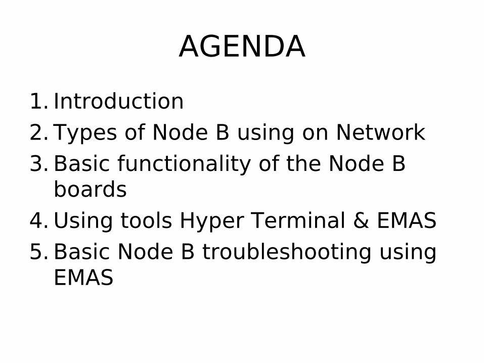
AGENDA
1. Introduction2. Types of Node B using on Network3. Basic functionality of the Node B
boards4. Using tools Hyper Terminal & EMAS5. Basic Node B troubleshooting using
EMAS
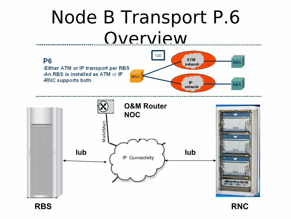
Node B Transport P.6 Overview
RBS RNC
O&M Router NOC
Iub Iub

CBNL Transport Network Layout
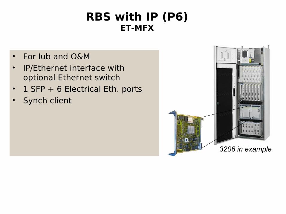
RBS with IP (P6)ET-MFX
• For Iub and O&M• IP/Ethernet interface with
optional Ethernet switch• 1 SFP + 6 Electrical Eth. ports• Synch client
3206 in example

Board functionality• ET-MFX(11)
– Designed for mass production in RBS quantities. (Cost efficient, good sourcing)
– Fast/Gigabit Ethernet– RBS User Plane IP termination
throttled to 150 Mbit/s in RBS version– Includes Ethernet switch

CBU
Ethernet
RS485
GPS /Ext.Ref
Power
ET1 & 2
ET3 & 4
RS-232/Prod.Test
CBU
CBU: A merge between SCB, GPB, TUB, and ETB
The CBU is the central control unit of the RBS. It executes the main part of the control functions in the RBS and controls the boards via the board processors.
Containing
• Power distribution to back plane
•Timing unit for network & radio synch with extended holdover time
• GPS interface for synch and positioning
• 4 x E1/T1/J1 ports
• Ethernet interface for site-LAN
• RS485 interface for control of fan and auxiliary equipment
• Main processor for RBS with 512Mbyte RAM and Flash disk
• IMA functionality
RUIF
Data F
Data E
Data D
Data C
Data B
Data A
RUIF
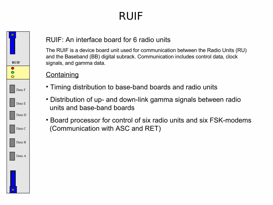
RUIF: An interface board for 6 radio units
The RUIF is a device board unit used for communication between the Radio Units (RU) and the Baseband (BB) digital subrack. Communication includes control data, clock signals, and gamma data.
Containing
• Timing distribution to base-band boards and radio units
• Distribution of up- and down-link gamma signals between radio units and base-band boards
• Board processor for control of six radio units and six FSK-modems (Communication with ASC and RET)
RU21
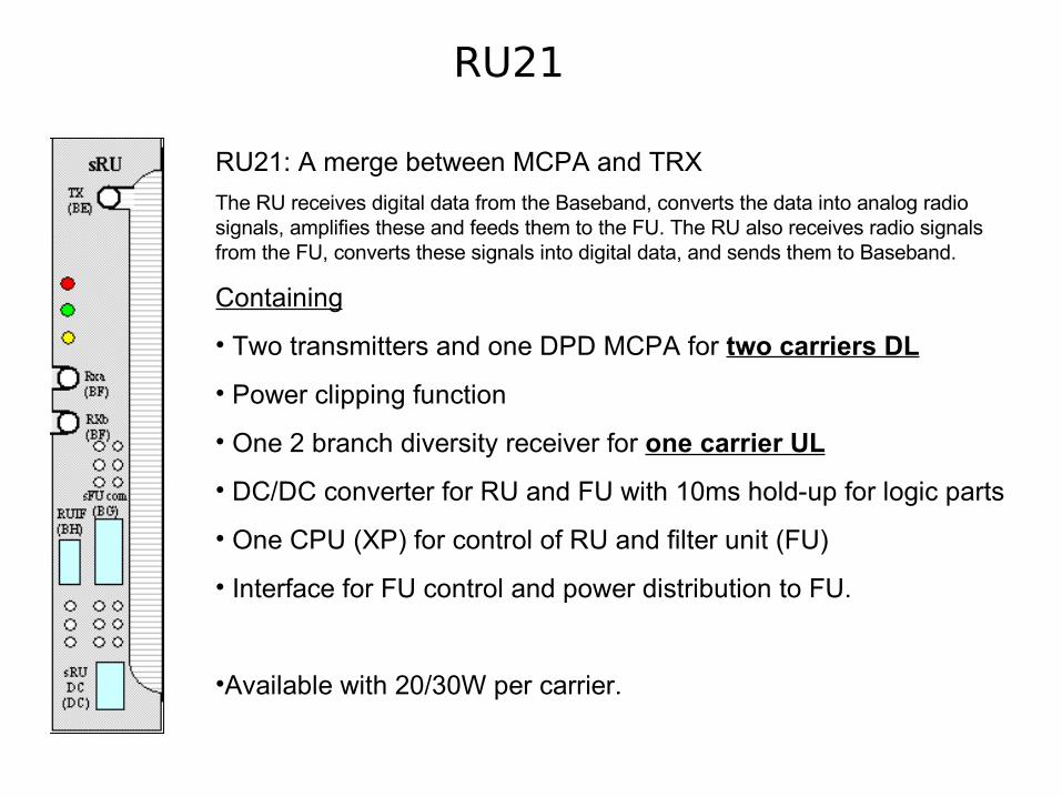
RU21: A merge between MCPA and TRX
The RU receives digital data from the Baseband, converts the data into analog radio signals, amplifies these and feeds them to the FU. The RU also receives radio signals from the FU, converts these signals into digital data, and sends them to Baseband.
Containing
• Two transmitters and one DPD MCPA for two carriers DL
• Power clipping function
• One 2 branch diversity receiver for one carrier UL
• DC/DC converter for RU and FU with 10ms hold-up for logic parts
• One CPU (XP) for control of RU and filter unit (FU)
• Interface for FU control and power distribution to FU.
•Available with 20/30W per carrier.
FU12
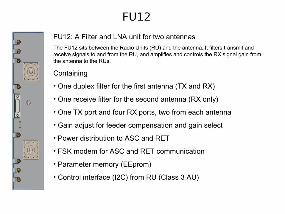
FU12: A Filter and LNA unit for two antennas
The FU12 sits between the Radio Units (RU) and the antenna. It filters transmit and receive signals to and from the RU, and amplifies and controls the RX signal gain from the antenna to the RUs.
Containing
• One duplex filter for the first antenna (TX and RX)
• One receive filter for the second antenna (RX only)
• One TX port and four RX ports, two from each antenna
• Gain adjust for feeder compensation and gain select
• Power distribution to ASC and RET
• FSK modem for ASC and RET communication
• Parameter memory (EEprom)
• Control interface (I2C) from RU (Class 3 AU)

MTN Ghana Node B Types
1. RBS 3206 (Indoor Cabinet / Multi sector)
2. RBS 3418 (Indoor Cabinet / Multi sector)
3. RBS 3518 (Indoor Cabinet / Multi sector)
4. RBS 3106 (Outdoor Cabinet / Multi sector)

RBS 3206 M
Position Description
A Connection Field (CF)
B Fan
C Fan Control Unit (FCU)
D Power Distribution Unit (PDU)
E Filter sub rack The filter sub rack contains the following: •Filter Unit (FU)
F The radio subrack contains the following: •Radio Unit (RU) Radio subrack also includes the digital casette, see below
G Digital cassette: •Control Base Unit (CBU) •Exchange Terminal (ET) board •Random Access and Receiver (RAX) board •Transmitter (TX) board •Radio Unit Interface (RUIF)

RBS 3206 M
Cabinet View Subrack View
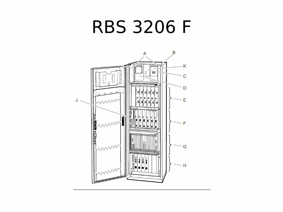
RBS 3206 F
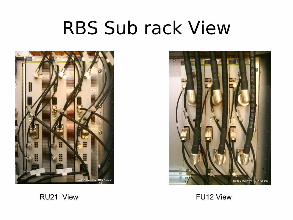
RBS Sub rack View
RU21 View FU12 View
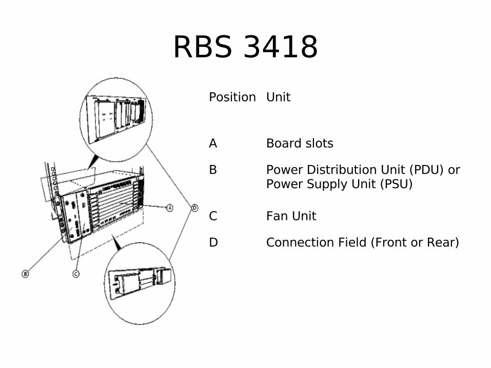
RBS 3418
Position Unit
A Board slots
B Power Distribution Unit (PDU) or Power Supply Unit (PSU)
C Fan Unit
D Connection Field (Front or Rear)

RBS 3418 View

RBS 3518Position Unit
1 Site LAN interface
2 OIL interfaces
3 Transmission connection interfaces
4 External alarm interfaces
5 ESD interface
6 Earth grounding interface (underneath the cabinet)
7 Power interface
8 GPS (optional)
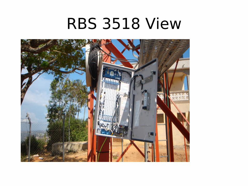
RBS 3518 View
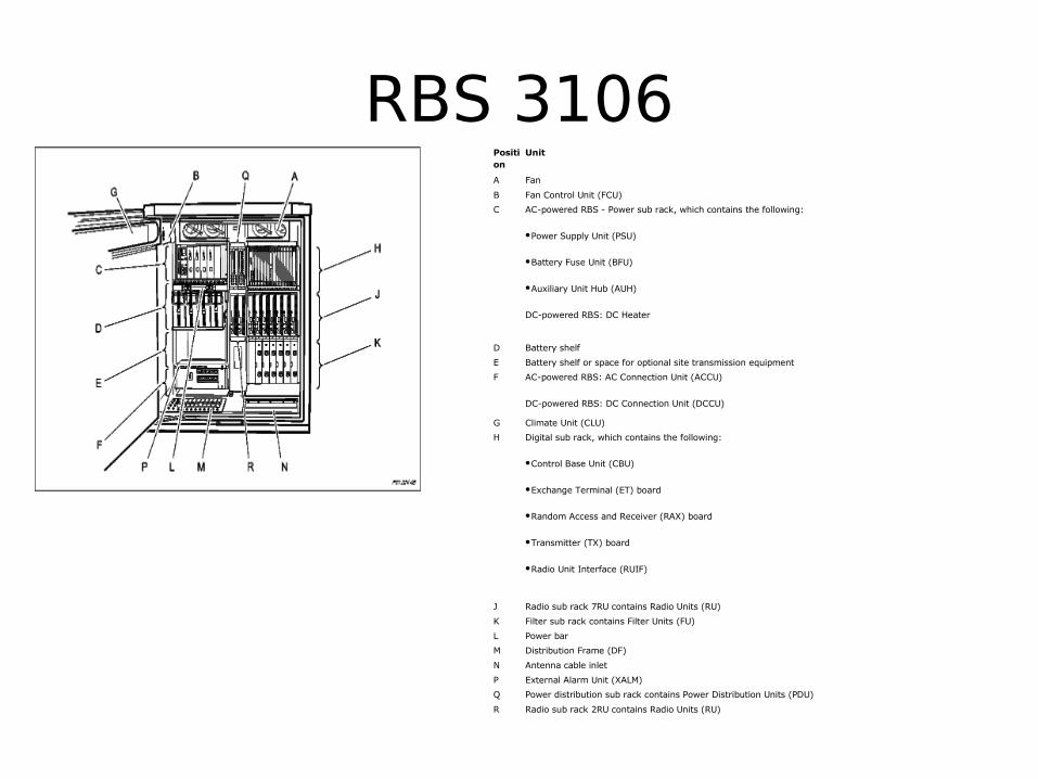
RBS 3106Position
Unit
A Fan
B Fan Control Unit (FCU)
C AC-powered RBS - Power sub rack, which contains the following:
•Power Supply Unit (PSU)
•Battery Fuse Unit (BFU)
•Auxiliary Unit Hub (AUH)
DC-powered RBS: DC Heater
D Battery shelf
E Battery shelf or space for optional site transmission equipment
F AC-powered RBS: AC Connection Unit (ACCU)
DC-powered RBS: DC Connection Unit (DCCU)
G Climate Unit (CLU)
H Digital sub rack, which contains the following:
•Control Base Unit (CBU)
•Exchange Terminal (ET) board
•Random Access and Receiver (RAX) board
•Transmitter (TX) board
•Radio Unit Interface (RUIF)
J Radio sub rack 7RU contains Radio Units (RU)
K Filter sub rack contains Filter Units (FU)
L Power bar
M Distribution Frame (DF)
N Antenna cable inlet
P External Alarm Unit (XALM)
Q Power distribution sub rack contains Power Distribution Units (PDU)
R Radio sub rack 2RU contains Radio Units (RU)
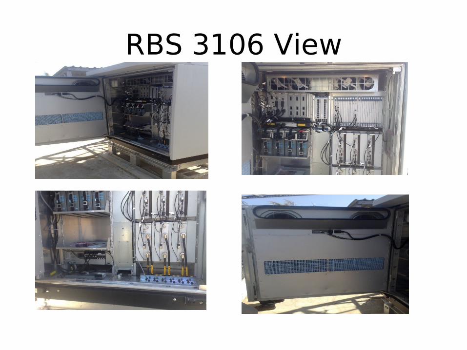
RBS 3106 View

Operation and Maintenace Overview
• This Document is provide you how to use the EMAS (Element Manager) for Operation and Maintenance Node B in P.6

1. Open your HyperTerminal New Connection.
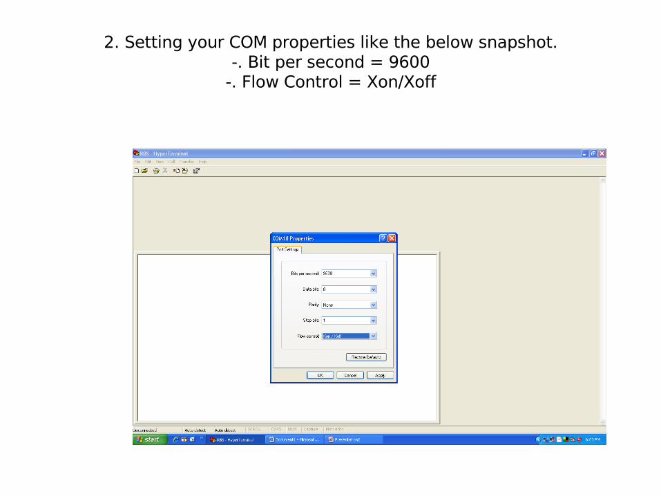
2. Setting your COM properties like the below snapshot.-. Bit per second = 9600
-. Flow Control = Xon/Xoff
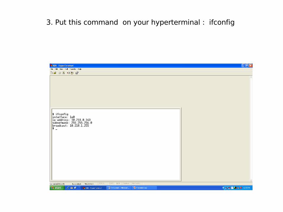
3. Put this command on your hyperterminal : ifconfig

4. Go to your LAN ( Local Area Connection ) Configure the IP of your Laptop.

5. Open your RBS Element Manager Enter the IP of the Node and Click connect.
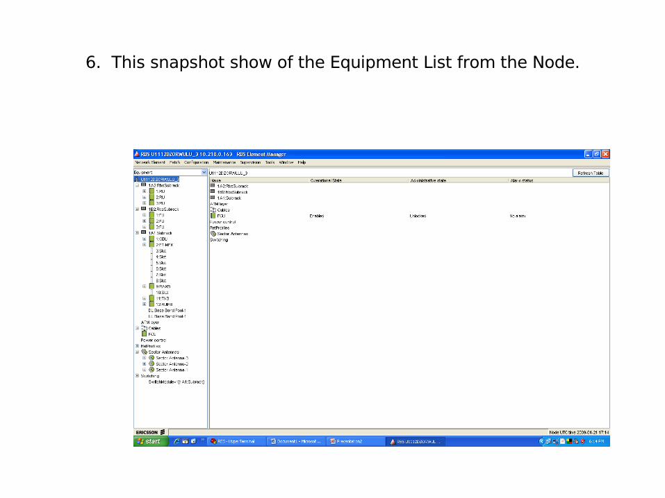
6. This snapshot show of the Equipment List from the Node.
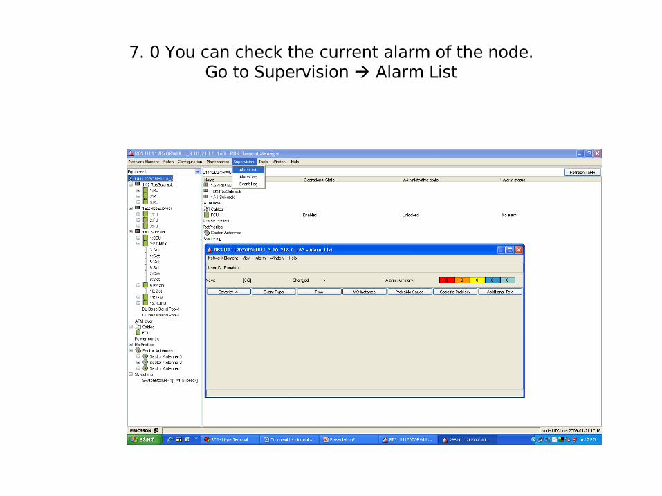
7. 0 You can check the current alarm of the node.Go to Supervision Alarm List

7.1 . You can check the current alarm of the node.Go to Supervision Alarm List
right click on the alarm choose alarm details
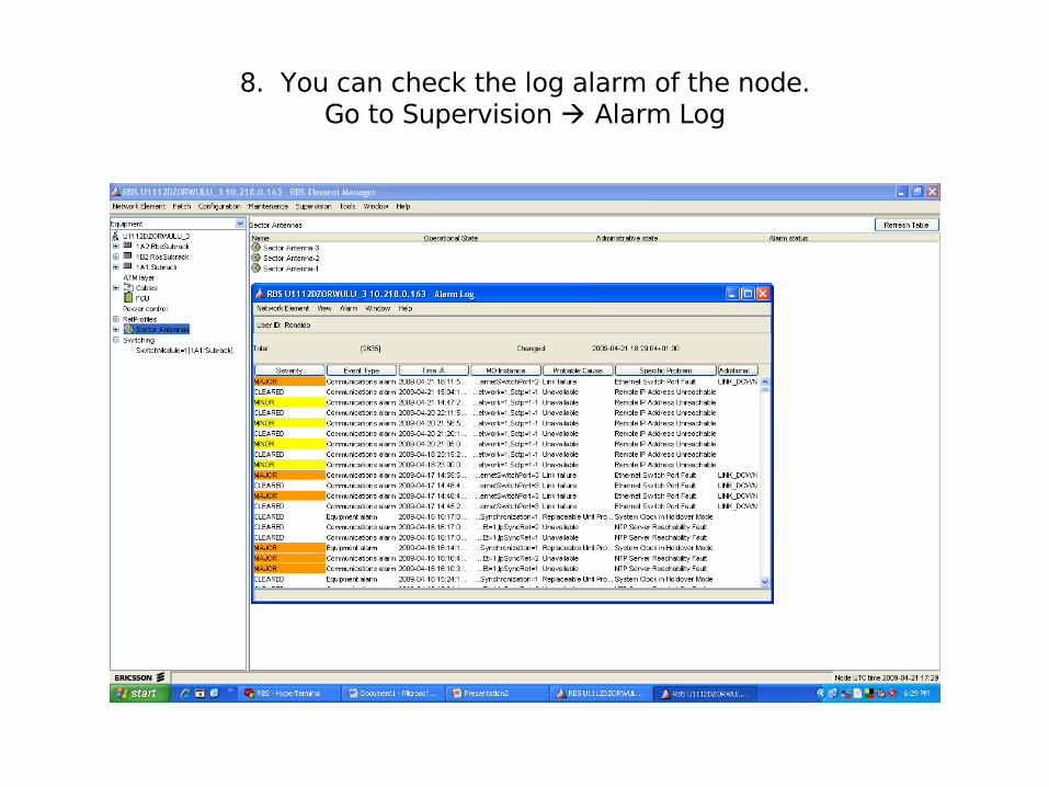
8. You can check the log alarm of the node.Go to Supervision Alarm Log

9. If some board is faulty, you can make sure from the test board tools.
Go to Maintenance Test Board
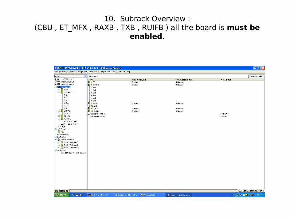
10. Subrack Overview :(CBU , ET_MFX , RAXB , TXB , RUIFB ) all the board is must be
enabled.
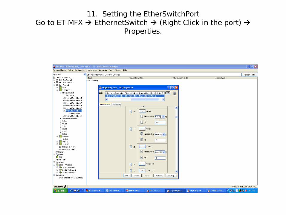
11. Setting the EtherSwitchPortGo to ET-MFX EthernetSwitch (Right Click in the port)
Properties.

12. Setting the InternalEthernetPort Go to ET-MFX InternalEthernetPort (right click) properties
defaultRouter0 = 10.216.3.254 defaultRouter1= 10.216.3.253
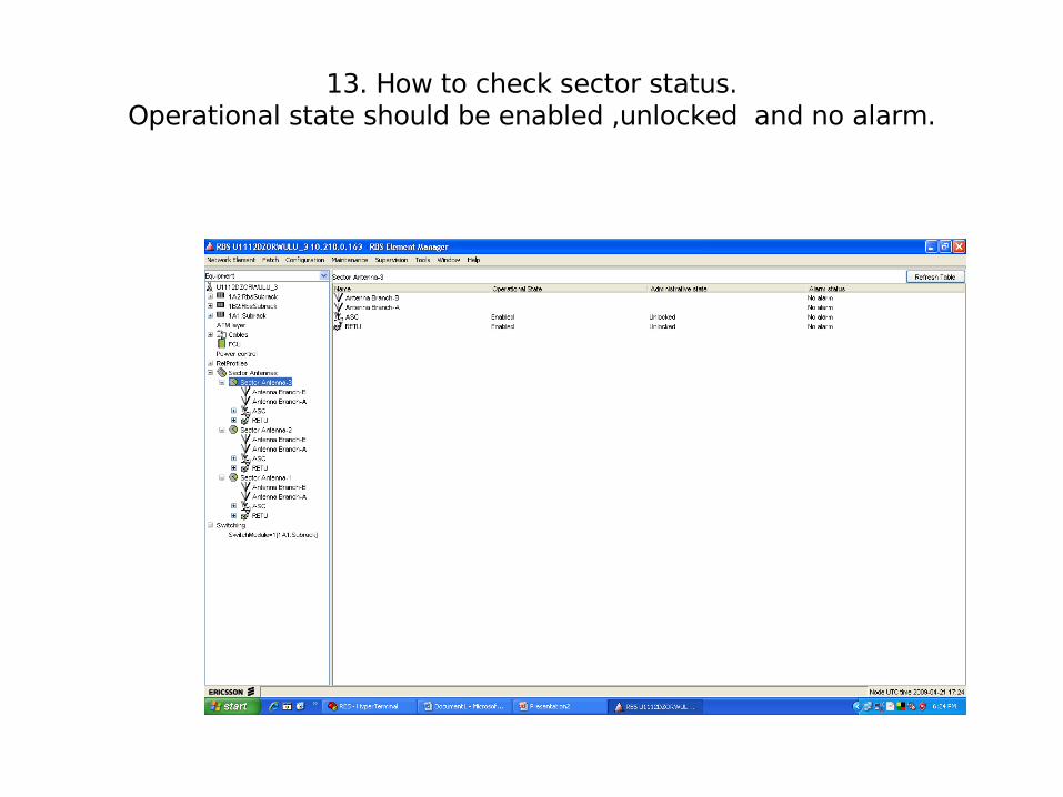
13. How to check sector status.Operational state should be enabled ,unlocked and no alarm.
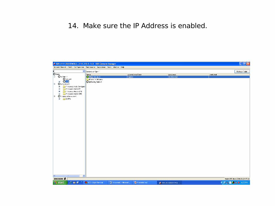
14. Make sure the IP Address is enabled.
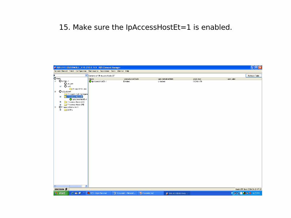
15. Make sure the IpAccessHostEt=1 is enabled.
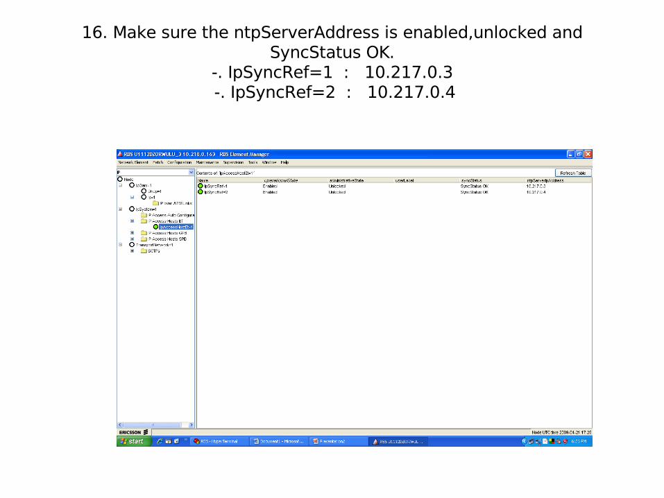
16. Make sure the ntpServerAddress is enabled,unlocked and SyncStatus OK.
-. IpSyncRef=1 : 10.217.0.3 -. IpSyncRef=2 : 10.217.0.4

17. Make sure the IpAccessHostGpb=1-1-1 is enabled unlocked.

18. Make sure the Sctp=1-1 is enabled and reserved Yes.
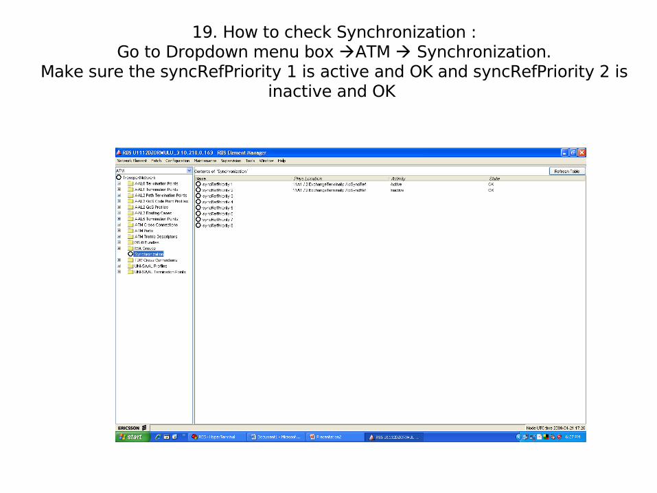
19. How to check Synchronization :Go to Dropdown menu box ATM Synchronization.
Make sure the syncRefPriority 1 is active and OK and syncRefPriority 2 is inactive and OK
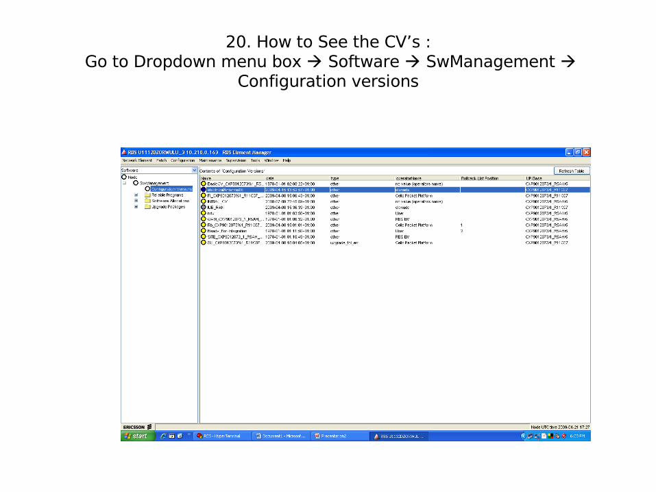
20. How to See the CV’s : Go to Dropdown menu box Software SwManagement
Configuration versions
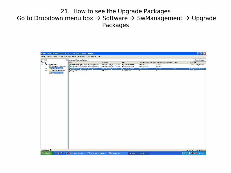
21. How to see the Upgrade Packages Go to Dropdown menu box Software SwManagement Upgrade
Packages
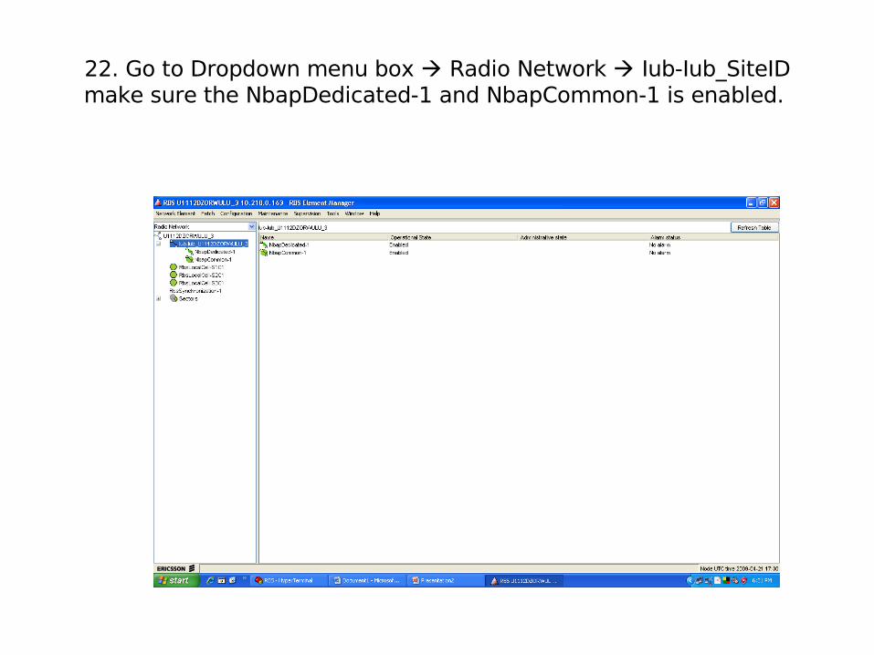
22. Go to Dropdown menu box Radio Network Iub-Iub_SiteIDmake sure the NbapDedicated-1 and NbapCommon-1 is enabled.
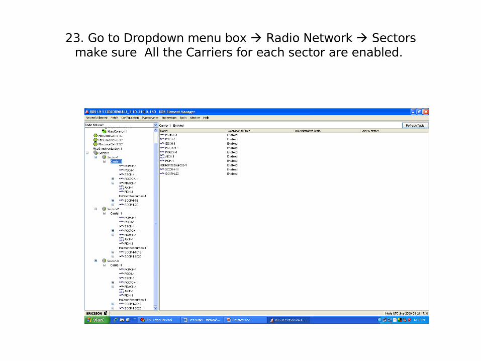
23. Go to Dropdown menu box Radio Network Sectorsmake sure All the Carriers for each sector are enabled.
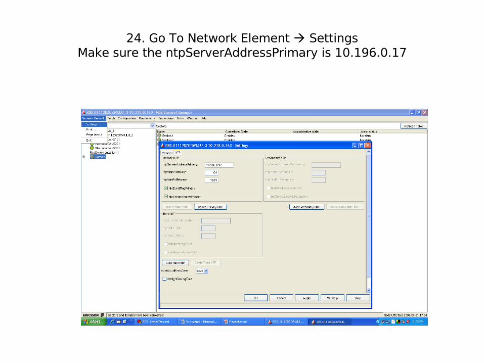
24. Go To Network Element SettingsMake sure the ntpServerAddressPrimary is 10.196.0.17
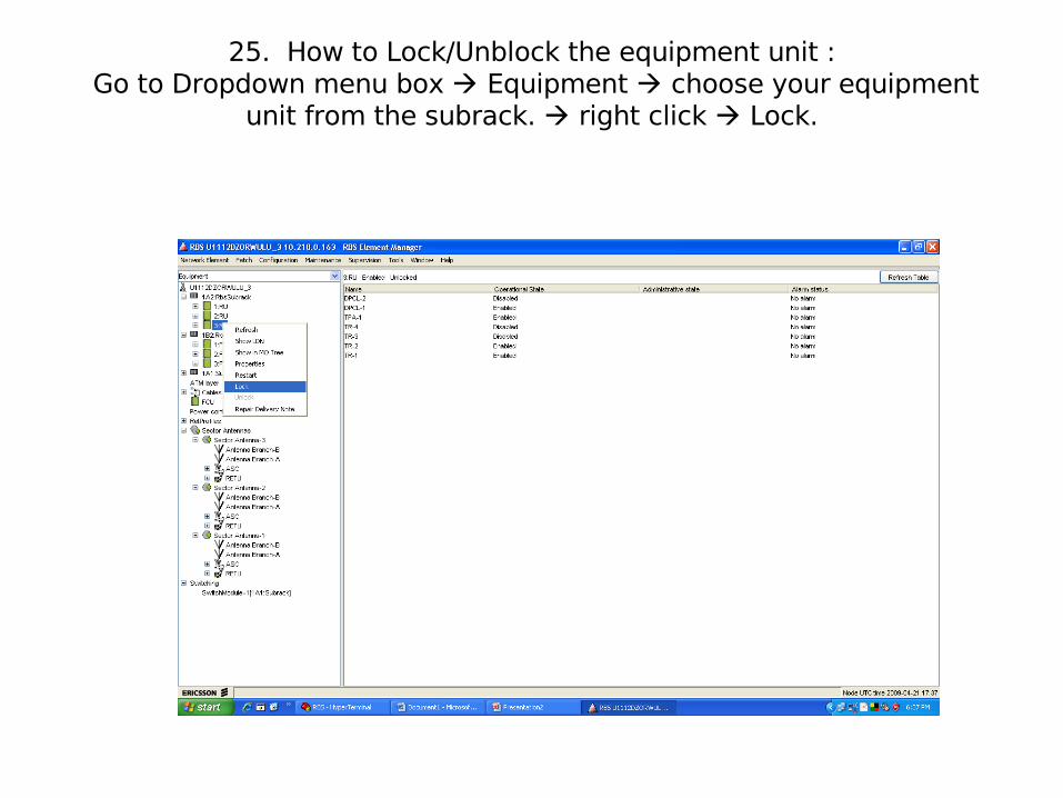
25. How to Lock/Unblock the equipment unit : Go to Dropdown menu box Equipment choose your equipment
unit from the subrack. right click Lock.

26. How to Restart the equipment unit : Go to Dropdown menu box Equipment choose your equipment
unit from the subrack. right click Restart