3ds max 8 Visual Handbook - Lightweaverlightweaver.com/images/3ds max VH.pdf · 3ds max is one of...
23
3ds max 8 Visual Handbook Michele Matossian
Transcript of 3ds max 8 Visual Handbook - Lightweaverlightweaver.com/images/3ds max VH.pdf · 3ds max is one of...

3ds max 8 Visual Handbook
Michele Matossian

Dedication
To My Art Teachers

Table of Contents i
CONTENTS AT A GLANCEIntroduction v
Chapter 1: Getting Started 1
Chapter 2: Creating Objects 31
Chapter 3: Viewport Navigation and Display 75
Chapter 4: Object Selection and Display 107
Chapter 5: Transforms 127
Chapter 6: Modifying Objects 159
Chapter 7: Animation 195
Chapter 8: Editing Meshes and Polymeshes 231
Chapter 9: Editing Shapes 275
Chapter 10: Compound Objects 303
Chapter 11: Lights 335
Chapter 12: Cameras 375
Chapter 13: Materials 401
Chapter 14: Maps 431
Chapter 15: Rendering 461
Appendix A: Icons 493
Appendix B: Keyboard Shortcuts 501
Index 505

3ds max 6 Visual Handbookii
TABLE OF CONTENTSIntroduction v
Chapter 1: Getting Started 1Installing 3ds max 6 2Setting Up 3ds max 6 4Accessing Tech Support 6Touring the Interface 7Special Controls 8Managing Files 17
Chapter 2: Creating Objects 31About Creating Objects 32Creating Mesh Objects 37Creating Shape Splines 58Precision Aids 71
Chapter 3: Viewport Navigation and Display 75Getting Your Bearings 76Putting It in Perspective 78Customizing Viewports 80Viewport Resolution 89Navigating Viewports 92Test Rendering 106
Chapter 4: Object Selection and Display 107Selecting Objects 108Region Selection 110Selecting by Name 115Grouping Objects 117Changing Object Display 121
Chapter 5: Transforms 127Transform Tools 128Transform Gizmos 131Advanced Controls 135Precision Aids 139Cloning 145Using Advanced Transforms 148

Table of Contents iii
Chapter 6: Modifying Objects 159Using Modifiers 160Deformation Modifiers 166Using Multiple Modifiers 173Subdividing Surfaces 176Rendering Modifiers 179Spline Modifiers 185Animating with Modifiers 189Using XForm Modifiers 192
Chapter 7: Animation 195Moving Through Time 196Configuring Time 198Keyframing 204Working with Keys 209Working with Controllers 213Bézier Controllers 218Adding Sound 222Constraining Animations 225Linking Objects 227
Chapter 8: Editing Meshes and Polymeshes 231Mesh Sub-Object Selection 232Transforming Mesh Sub-Objects 240Modifying Mesh Sub-Objects 244Editing Mesh Objects 245Editing Polymeshes 258Polymesh Sub-Object Selection 258Editing Polymesh Objects 264
Chapter 9: Editing Shapes 275Shape Sub-Objects 276Adjusting Curvature 284Editing Shapes 288
Chapter 10: Compound Objects 303Creating Boolean Objects 304Lofting Objects 314Editing Lofts 320Morphing Objects 324AEC Objects 328

3ds max 6 Visual Handbookiv
Chapter 11: Lights 335Illuminating Scenes 336Creating Lights 337Casting Shadows 347Controlling Illumination 355Navigating Lights 365Animating Lights 372
Chapter 12: Cameras 375Viewing Scenes 376Creating Cameras 377Adjusting Cameras 381Navigating Cameras 388Animating Cameras 396
Chapter 13: Materials 401Using the Material Editor 402Using Material Libraries 412Standard Materials 415Compound Materials 426
Chapter 14: Maps 431About Maps and Mapping 432Browsing Maps 433Creating Maps 436Adding Maps to Materials 443Applying Mapping Coordinates to Objects 448Using Environment Maps 452Reflection and Refraction 455
Chapter 15: Rendering 461Rendering Scenes 462Rendering Effects 475
Appendix A: Icons 493
Appendix B: Keyboard Shortcuts 501
Index 505
INTRODUCTION
3ds max is one of the most powerful desktop 3D graphics programs availabletoday. It is used for a wide variety of commercial and artistic applications,including architecture, computer games, film production, web design, forensics,medical visualization, scientific visualization, virtual reality, and fine art.
This book was written for artists, designers, students, teachers, working profes-sionals, and anyone who wants to build their dreams.At the beginning of eachchapter, the introduction gives you a sense of the possibilities.The sectionheadings present the theory you need just in time to do the step-by-step tasksthat follow.Tips and tables give you important clues about pitfalls, shortcuts,and advanced techniques. By studying both the theory and the mechanics, youwill be equipped not only to push the right buttons, but also to create art,solve problems, and invent solutions.
This book is designed to be as clear as possible and presumes no prior experi-ence on the part of the reader.To assist your learning, over 1400 figures showyou what to do and how to do it. By the end of this book, you will havelearned how to create, model, map, animate, and render objects in 3ds max 7.
To get the most out of this book, you should be familiar with the Windowsenvironment and have access to an installation of 3ds max 7.You should alsohave a good understanding of a 2D graphics program like Adobe Photoshop.
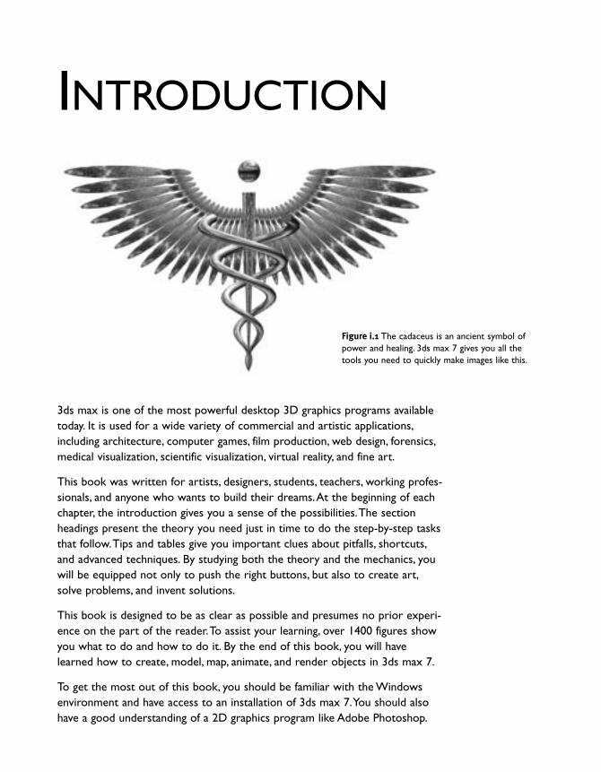
Figure i.1 The cadaceus is an ancient symbol ofpower and healing. 3ds max 7 gives you all thetools you need to quickly make images like this.

3ds max 6 Visual Handbookvi
There are as many ways to work in 3ds max as there are artists who usethe program. By breaking down complex ideas into plain English and careful-ly organizing the information, I have tried to present the material in such away that you can quickly find what you need and apply it.
The chapters of the book are meant to be followed in order, but each oneis designed to be able to stand alone. If you are new to 3ds max, the bestthing to do is start at the beginning and work your way through the topicsin order. More advanced students may want to skip to areas of particularinterest.To use this book as a “how to” reference, look up your task in thetable of contents or look up topics in the index. Extensive tables of com-mands may be found in the chapters as well as in the appendices.
Chapter 1 gets you up and running, from installing the program to navigatingthe interface and learning essential file commands.
Chapters 2–4 teach you how to create and select objects, control the dis-play, render images, and navigate 3D scenes. Since the last edition of thisbook, new objects, group commands, and sidebars have been added.
Chapters 5–7 show you how to manipulate and animate objects usingtransforms, modifiers, and animation controllers.The sequence of topics hasbeen significantly revised, in accordance with changes to the user interfaceas well as for clarity.
Chapters 8–10 explain more advanced modeling techniques, including sub-object editing and compound objects. New to this edition are sections onpolymesh editing in Chapter 8 and AEC Objects in Chapter 10.
Chapters 11 and 12 describe the use of lights and cameras for illuminatingand composing views of your scenes.The section on animating cameras inChapter 12 has been expanded to include more on walkthrough, flythrough,and flyby animations.
Chapters 13 and 14 cover materials and mapping, so that you can makeyour scenes realistic as well as beautiful. Special care went into these chaptersto make the figures larger and more beautiful.
Chapter 15 rounds out the book with rendering and shows you how to addeffects to produce high-quality pictures and movies. Many new figures havebeen added here for clarity, beauty, and visual interest.
Enjoy!
Michele [email protected]

Everything in nature can be represented with acombination of geometric forms. As the pain-ter Paul Cézanne once wrote,“Treat nature in
terms of the cylinder, the sphere, the cone; everythingin proper perspective.” He also is also reported tohave said,“One must first of all study geometricforms: the cone, the cube, the cylinder, the sphere.”
Today, 3D artists use geometric forms called objects
to create and animate entire worlds. Starting with
the cone, the cube, the cylinder, and the sphere
(FFiigguurree 22..11), you can combine and manipulate basic
objects to create highly complex and realistic scenes.
This chapter explains how to create mesh objects
and shape splines, which are the basic building blocks
of 3D scenes.You will also learn how to create
helper objects to assist you in placing objects in
your scene. In later chapters, you will learn to create
lights and cameras, and to create compound objects
by combining objects together.
FFiigguurree 22..11 The cone, the cube, the cylinder, and thesphere are basic objects in 3ds max.
2CREATINGOBJECTS

32
AAbboouutt CCrreeaattiinngg OObbjjeeccttss3ds max is written in an oobbjjeecctt-oorriieenntteedd programminglanguage called C++.This means that the state of anobject determines which commands may be appliedto it. If a command may not be applied to an object,the command becomes unavailable, until the objectchanges to an appropriate state.
When you create an object in 3ds max, the programautomatically assigns it a name, color, position, orien-tation, pivot point, axis tripod, display properties, andrendering properties. If an object can be renderedto an image output file, a white bboouunnddiinngg bbooxx appearsat the dimensional extents of the object when it isselected (FFiigguurree 22..22)..
As you place objects in a scene, the viewports dis-play them from different angles.The Front, Left, andTop viewports always view objects from the front,left, and top of the world. By default, objects inthese views are displayed in wwiirreeffrraammee. In contrast,the Perspective viewport can display an object fromany angle. By default it looks at the scene from infront and a little above, and draws objects using asmooth shaded mode of display (FFiigguurree 22..33).
The grids that you see in the viewports are all part of the hhoommee ggrriidd.The home grid provides construc-tion planes for creating objects.What this means isthat objects automatically sit on top of the gridwhen they are created. Because the grids of thehome grid are perpendicular to one another, objectscreated in different viewports may orient in differentdirections (FFiigguurree 22..44)..
For more information on navigating viewports and viewport modes of display, see Chapter 3,“Viewport Navigation and Display.”
FFiigguurree 22..22 The axis tripod and bounding box are dis-played when the object is selected.The origin of theaxis tripod is located at the pivot point of the object;the bounding box is drawn at the object’s extents.
FFiigguurree 22..33 Viewing a scene from four different angles.Three of the views are displayed in wireframe; thePerspective view is shaded.
FFiigguurree 22..44 The home grid consists of three inter-secting grids. Creating objects on different gridsorients them to different directions in space.
World Axis Axis Tripod Bounding Box
3ds max 6 Visual Handbook

2 Creating Objects
Most objects that you create in 3ds max start outas ppaarraammeettrriicc oobbjjeeccttss. Parametric objects are mathe-matically defined forms that you give exact size andproportion by assigning numerical values calledppaarraammeetteerrss. Objects that define basic geometricforms are known as ppaarraammeettrriicc pprriimmiittiivveess, or simplypprriimmiittiivveess.
NNoonn-ppaarraammeettrriicc oobbjjeeccttss are created by convertingthem from parametric objects or by building themfrom smaller components. Rather than being definedby mathematical equations, non-parametric objectsare defined by explicit descriptions of each of theirparts. Most non-parametric objects include built-incommands for editing their structures. Such objectsare called eeddiittaabbllee oobbjjeeccttss in 3ds max.
All commands for creating objects are found in thetab panels and drop-down menus of the Createcommand panel (FFiigguurree 22..55).. For your convenience,3ds max provides shortcuts to some of these commands:
● CCrreeaattee mmeennuu (FFiigguurree 22..66).. Organized by objecttype, contains shortcuts to nearly all of the objectcreation commands in a series of flyout menus.
● PPrriimmiittiivveess qquuaadd mmeennuu (FFiigguurree 22..77).. Contains short-cuts to the most commonly created primitives.Access this menu by Ctrl + right-clicking in anyviewport.
● RReeaaccttoorr ppaanneell. Contains advanced objects forsimulating complex physical phenomena (FFiigguurree 22..88).. Found on the left-hand side of theuser interface, this panel may be dragged by itsupper edge and closed when not in use.
33
FFiigguurree 22..66 The Create menu contains shortcuts to most of theobject creation commands.
FFiigguurree 22..77 The primitivesquad menu containsshort-cuts for creatingthe most commonlyused primivies.
FFiigguurree 22..55 The Create command panel contains the object creation commands.
FFiigguurree 22..88 The Reactor panel contains shortcuts to commands for creating simulations of physical phenomena.

3ds max 6 Visual Handbook
To create an object by clicking anddragging:
11.. In the Create panel, click the button for theobject you want to create.
The creation rollouts for the object appear(FFiigguurree 22..99)..
22.. Choose an option from the Creation Methodrollout, or simply use the default.
33.. In the Perspective viewport, click and dragacross the grid to create the base of the object.Release the mouse button when the base is theright size (FFiigguurree 22..1100).
44.. If the object is not complete, move and click toset other parameters as needed.
55.. In the Parameters rollout, adjust the parametersof the object by entering new values into theinput fields or by dragging their spinners.
The object updates in the viewport interactively(FFiigguurree 22..1111).
66.. Right-click in any viewport to exit object-creation mode.
34
FFiigguurree 22..99 The teapot creation rollouts.
FFiigguurree 22..1100 The quickest way to create a mesh objectis to click and drag.
FFiigguurree 22..1111 Increasing the value of the Radius parameterincreases the size of the teapot.
Spinners
TThhee UUttaahh TTeeaappoottStudents often ask me why the Teapot objectis included among the Standard Primitives.After all, how many forms are based onteapots? It all started in the 1970s at theUniversity of Utah when a computer graphicsresearcher named Martin Newell created anelegant wireframe model of a teapot. His colleague, James Blinn, used the teapot toexperiment with methods of surface rendering.Soon, so many people were making reflectingteapots that the “Utah Teapot” becameimmortalized as a symbol of the field.
2 Creating Objects
To create an object using the keyboard-entry method:
11.. Activate the Perspective viewport.
22.. In the Create panel, click on the button for theobject you want to create.
33.. Open the Keyboard Entry rollout, and enter thedimensions of the object.
If you want to position the object in a placeother than the origin, enter location coordinatesfor X,Y, and Z as well.
44.. Click Create (FFiigguurree 22..1122).
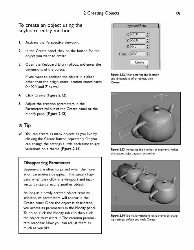
55.. Adjust the creation parameters in theParameters rollout of the Create panel or theModify panel (FFiigguurree 22..1133).
! Tip
✔ You can create as many objects as you like byclicking the Create button repeatedly. Or youcan change the settings a little each time to getvariations on a theme (FFiigguurree 22..1144).
35
FFiigguurree 22..1122 After entering the locationand dimensions of an object, clickCreate.
FFiigguurree 22..1133 Increasing the number of segments makesthe teapot object appear smoother.
FFiigguurree 22..1144 You make variations on a theme by chang-ing settings before you click Create.
DDiissaappppeeaarriinngg PPaarraammeetteerrssBeginners are often surprised when their cre-ation parameters disappear. This usually hap-pens when they click in a viewport and inad-vertantly start creating another object.
As long as a newly-created object remainsselected, its parameters will appear in theCreate panel. Once the object is deselected,you access its parameters in the Modify panel.To do so, click the Modify tab and then clickthe object to reselect it.The creation parame-ters reappear. Now you can adjust them asmuch as you like.

36 3ds max 6 Visual Handbook
3ds max automatically assigns names to objectsbased on the object type and the order in which itwas created. For example, the first, second, and thirdsphere that you create will be named Sphere01,Sphere02, and Sphere03. After you create yourobjects, it is helpful if you assign more descriptivenames so you can identify them quickly when yourscene becomes more complex.
3ds max also assigns colors to objects as you createthem. By default, color assignment is random, butyou can change the color of objects after they arecreated, or set an option so that all objects areassigned the same color.
To assign a name and a color to anobject:
11.. Create an object, or select an existing object byclicking on it.
22.. In the Create panel, highlight the name of theobject in the Name and Color rollout (FFiigguurree 22..1155).Then enter a new name.
33.. Click on the color swatch located just to theright of the name field.
The Object Color dialog box appears (FFiigguurree 22..1177).
44.. Click on a swatch to pick color, and click OK.
The object changes to the new shade.
55.. To assign the same color to objects as you cre-ate them, uncheck Assign Random Colors in theObject Color dialog box.
66.. To assign the same color to existing objects,click and drag a selection region around thembefore picking a color (FFiigguurree 22..1188). Note thatyou cannot assign a name to a multiple selection.
FFiigguurree 22..1155 Highlight the name of theobject.
FFiigguurree 22..1166 Pickia color from the Object Color dialog box.
FFiigguurree 22..1177 Selecting a group of objects by dragging aselection window around them.

372 Creating Objects
AAbboouutt MMeesshh OObbjjeeccttssMesh primitives come in two varieties: SSttaannddaarrddPPrriimmiittiivveess,, which include basic geometric forms, andEExxtteennddeedd PPrriimmiittiivveess, which are more complex objects.By clicking on different object types, you can quicklycreate objects from predefined forms.
The components of a mesh object include:
VVeerrttiicceess point locations in space.
EEddggeess lines that connect vertices.
FFaacceess triangular surfacesbounded by 3 edges and 3 vertices.
SSuurrffaaccee nnoorrmmaallss, or normals for short, are vectorsthat stick straight up from the center of each face.By indicating which direction each face is “facing.”they help the progarm determine which side to render and what value, based on current lightingconditions, to shade the face (FFiigguurree 22..1188).
SSmmooootthhiinngg creates gradations of value across meshsurfaces by averaging the intensity of light betweenvertices.The more vertices that are present, thesubtler the gradations will be, and the smoother the mesh surface will appear (FFiigguurree 22..1199).
In the next few pages, I’ll show you how to createobjects using the click and drag method.After youmaster this simple technique, try creating a fewobjects with the keyboard entry method to seewhat this approach has to offer.
EdgeVertex Face Normal
FFiigguurree 22..1188 Mesh objects are made up of vertices,edges and faces. Surface normals in the middle of eachface determine which side of the face is rendered.
FFiigguurree 22..1199 When a mesh object is smoothed, edge divisions disappear.Above: a teapot with unsmoothedfaces. Below: a teapot with smoothed faces.

3ds max 6 Visual Handbook
CCrreeaattiinngg SSttaannddaarrdd PPrriimmiittiivveess
There are ten Standard Primitives in 3ds max 6: theBox, Cone, Sphere, GeoSphere, Cylinder,Tube,Torus,Pyramid,Teapot, and Plane (FFiigguurree 22..2200).
Standard Primitives are found in the Geometrybranch of the Create panel, which is “on deck”when you start the program (FFiigguurree 22..2211). Shortcutsto these commands are located in the Create menu.
Shortcuts to the most commonly used primitivesare found in the primitives quad menu, as describedon page 33.
38
Figure 2.20 Standard Primitives are used to make basic geometric forms.
Figure 2.21 Standard Primitives are locatedin the Geometry branch of the Create panel.

39
FFiigguurree 22..2222 The main parameter of aSphere is its Radius.
FFiigguurree 22..2233 Click and drag to create the sphere.
Low-Poly Objects
Low-polygon count objects, or “low-polyobjects,” are the lifeblood of interactiveapplications like 3D games. Because theyhave fewer faces, low-poly objects can beredrawn more quickly than other objects.
With a GeoSphere, you can easily createlow-poly spheres, such as a tetrahedra,octahedra or icosahedra (above).
To find out how many faces there are in anobject, select the object, and press 7.Thistoggles the display of the Polygon Counter,which appears in the upper-left corner of theactive viewport.
To create a sphere:
11.. In the Create panel, click Sphere.The Sphere creation rollout appears (FFiigguurree 22..2222).
22.. In the Perspective viewport, click and drag asphere of any size (FFiigguurree 22..2233).
33.. Release the mouse button to set the radius.
! Tips
✔ To make a round object appear smoother,increase the Sides parameter. To make theobject appear faceted, uncheck Smooth.
✔ To make a sphere sit on top of the grid,check Base to Pivot.This moves the pivotpoint of the object to its base.
2 Creating Objects

3ds max 6 Visual Handbook
To create a box:
11.. In the Create panel, click Box.
The Box creation rollout appears (FFiigguurree 22..2244).
22.. In the Perspective viewport, click and dragacross the grid to form the base of the box.
33.. Release the mouse button to set the length andwidth of the box (FFiigguurree 22..2255).
44.. Without clicking, move the cursor upward inthe viewport.
55.. Click to set the height (FFiigguurree 22..2266).
! Tips
✔ Planes are simple to create.You just click anddrag to set the length and width, as in step 2.
✔ To create a box that hangs below the grid plane,move the cursor downward in step 4.
✔ To create a box with equal sides, choose Cubein the Creation Method rollout.
40
Figure 2.24 A box has inputs for length,width, and height.
Figure 2.25 Drag to set the length and width.
Figure 2.26 Move and click to set the height.

2 Creating Objects
To create a pyramid:
11.. In the Create panel, click Pyramid.The Pyramid creation rollout appears (FFiigguurree 22..2277).
22.. In the Perspective viewport, click and dragacross the grid to form the base of the pyramid.
33.. Release the mouse button to set the widthand depth of the base (FFiigguurree 22..2288).
44.. Without clicking, move the cursor upward inthe viewport.
55.. Click to set the height (FFiigguurree 22..2299).
! Tips
✔ To create a square base for a box, plane, orpyramid, hold down the Ctrl key as you dragout the base. In this method, the first clicksets the center of the base, and draggingcauses the base to grow equally in all direc-tions.
✔ To increase the number of divisions in a box,plane, or pyramid, increase the segmentparameter values.
41
Figure 2.27 A pyramid has width anddepth as well as height.
Figure 2.28 Drag to set the base of the pyramid.
Figure 2.29 Move and click to set the height.

3ds max 6 Visual Handbook
Cylinders have a radius and a height. Cones, torii,and tubes have two radii and a height..
To create a cylinder:
11.. In the Create panel, click Cylinder.
The Cylinder creation rollout appears (FFiigguurree 22..3300).
22.. In the Perspective viewport, click and drag thebase of the cylinder. Release the mouse buttonto set the radius (FFiigguurree 22..3311).
33.. Without clicking, move the cursor up in theviewport.
44.. Click to set the height (FFiigguurree 22..3322).
! Tip
✔ To slice a radial object like you slice an apple,check Slice.Then set the beginning and end ofthe slice in degrees of arc by entering SliceFrom and Slice To values.
42
Figure 2.30 A cylinder has a radius and aheight. It can also be sliced.
Figure 2.31 Drag outward to set the radius.
Figure 2.32 Drag upward and click to set the height.
Slicing a Pie
Using the keyboard entry method, you can cre-ate and slice mulitple cylinders that fit togetherlike the pieces of a pie.

43
A cone is created in the same manner as a cylin-der, with two additional steps at the end.
To create a cone:
11.. In the Create panel, click Cone.
The Cone creation rollout appears (FFiigguurree 22..3333).
22.. In the Perspective viewport, click and dragthe base of the cone. Release the mouse button to set the base radius (FFiigguurree 22..3344).
33.. Without clicking, move the cursor up in theviewport.
44.. Click to set the height (FFiigguurree 22..3355).
55.. Without clicking, move the cursor down toestablish the radius for the top.
If you want to close up the point at the topof the cone, drag downward from the topuntil it closes up.
66.. Click to set the radius of the top (FFiigguurree 22..3377).
! Tip
✔ You can make the radius of the top widerthan the radius of the base by draggingupward in the viewport in step 6.
2 Creating Objects
Figure 2.33 A cone has two radii.
Figure 2.34 AFter dragging out the base, drag upward toset the height.
Figure 2.35 Move down and click to complete the top.

Fun with Parameters
If you take a closer look at some of the objectcreation parameters, you will find that you canmake a lot of interesting variations. For example,this torus was created by setting Twist to 360,Segments to 54 and Smooth to None.
3ds max 6 Visual Handbook
The second radius of a torus defines the thicknessof its cross section.
To create a torus:
11.. In the Create panel, click Torus.The Torus creation rollout appears (FFiigguurree 22..3366).
22.. In the Perspective viewport, place the cursorwhere you want the center of the torus to be.Then click and drag outward.
33.. Release the mouse button to set the first radius(FFiigguurree 22..3377).
44.. Without clicking, move the cursor back towardthe center of the torus.
55.. Click to set thickness of the torus (FFiigguurree 22..3388).
44
Figure 2.38 A torus has two radii.
Figure 2.39 Drag outward to set the first radius.
Figure 2.40 Drag inward to set the second radius.

45
A tube has an inner and outer radius, as well as aheight.
To create a tube:
11.. In the Create panel, click Tube.
The Tube creation rollout appears (FFiigguurree22..3399).
22.. In the Perspective viewport, place the cursorwhere you want the center of the tube tobe.Then click and drag outward.
33.. Release the mouse button to set the firstradius (FFiigguurree 22..4400).
This will be the outer wall of the tube.
44.. Without clicking, move the cursor backtoward the center of the tube.
55.. Click to set the second radius (FFiigguurree 22..4411).
This defines the inner wall of the tube.
66.. Move the cursor up in the viewport.Thenclick to set the height (FFiigguurree 22..4422).
2 Creating Objects
Figure 2.39 A tube has two radii and height.
Figure 2.40 Drag inward to set the second radius.
Figure 2.41 The completed tube.