3D Swing Trajectory of the Club Head from Depth Shadow
5
Abstract—Using depth sensors like Microsoft Kinect for gesture recognition has recently drawn much academic attention. It is possible to recognize a user’s body parts from depth images and find joint positions. Yet, it is not easy to track the club heads in fast swing motion. The present paper draws on single depth images to propose a new method of tracking the hand and club head paths in swing motion. Although the club head depth information cannot be directly gained from a depth sensor, a 3D trajectory can be generated by tracking and refining the hand and club head positions based on the depth-related shadow region information (depth shadow), hand depth information and club head depth information in the initial swing. The present experimental findings indicate the proposed method can easily capture the 3D hand and club head positions in driver tee shot motion in a small room. Index Terms—Kinect, depth shadow, club head trajectory, depth image, hand position. I. INTRODUCTION The advent of the consumer depth camera (RGB-D) has triggered diverse research in the field of markerless gesture recognition, with a range of applications being released. As for games, cases of using users’ gestures as interfaces such as experience sports and dance games are on the rise. In sports, gesture recognition is applied to posture coaching. Yet, it is hard to precisely recognize gestures with a single depth sensor unit due to self-occlusion. Using multiple depth sensors minimizes invisible joint parts, solving the problem of joint occlusion, by restoring 3D gestures with camera calibration in combination with multi-joint data [1], [2]. As a method of estimating exact 3D postures from single depth images, the best matching pose is searched in a pre-captured motion database, and directly fitted to the depth value, so as to improve the initially estimated posture [3]. Shen et al. optimized the temporal motion consistency and the systematic bias to enhance the pose refinement and correction process [4]. However, the methods they suggested were intended to restore poses in line with the user’s gestures but cannot be applicable to tools for sporting motions (e.g. golf clubs). Analyzing golf swings using inertial sensors, S. Chun et al. attached inertial sensors onto the wrist and the grips on golf clubs to propose a golf coaching model capable of analyzing and assessing users’ uncocking motion [5]. C. N. K. Nam et al. used inertial sensors and stereo cameras to propose a Manuscript received August 10, 2015; revised January 15, 2016. This work was supported by Institute for Information & communications Technology Promotion (IITP) grant funded by the Korea government (MSIP) (No. B0101-15-0152) The authors are with Electronics and Telecommunications Research Institute, Daejeon, Korea (e-mail: [email protected], [email protected]). method of tracking the movement of golf clubs in golf swing motion [6]. Still, sensors need be attached to body parts or clubs, which is inconvenient. In a study intended to track a club’s trajectory from 2D images, V. Lepetit et al. viewed data association as a matter of motion model fitting, and used a sliding window including a few frames around the current frame, instead of tracking frames one by one, to fit the target object’s candidate position with a motion model, proposing a method of tracking the movement of a tennis ball or a golf club head [7]. N. Gehrig et al. applied a simple polar, polynomial approximation for modeling the club-head path, and generated the golf club’s path by experimentally modeling ordinary upswings with the 4th polar curve and downswings with the 6th polar curve [8]. Yet, it is hard to track a fast moving golf club in 2D images due to blurring. Also, the final output is a 2D path at best. As an inexpensive depth sensor, Microsoft Kinect takes a shot at 30fps maximum, and is not free from blurring images. This paper tracks the shadow region arising while capturing the depth images with Kinect to propose a new method of generating a 3D club head trajectory. Overview of Approach The present system uses the depth images (30fps@512×424) captured with a Kinect sensor unit. While a user is engaging in a swing motion, the body depth data can be captured without the fast moving club head depth data. Thus, there is no yielding the club-head position directly. That is why the analysis of swings with a single Kinect unit yields nothing but user’s body motion [9]. Fig. 1. Basic processing pipeline of algorithm. To find the shadow arising in depth images, the background depth images are gained first, and the grids are generated at the bottom (XZ plane) and the back side (XY plane). The number of depth points projected on the background and that of the depth points projected on the grid 3D Swing Trajectory of the Club Head from Depth Shadow Seongmin Baek and Myunggyu Kim International Journal of Computer Theory and Engineering, Vol. 9, No. 2, April 2017 92 DOI: 10.7763/IJCTE.2017.V9.1118
Transcript of 3D Swing Trajectory of the Club Head from Depth Shadow
Abstract—Using depth sensors like Microsoft Kinect for
gesture recognition has recently drawn much academic
attention. It is possible to recognize a user’s body parts from
depth images and find joint positions. Yet, it is not easy to track
the club heads in fast swing motion. The present paper draws on
single depth images to propose a new method of tracking the
hand and club head paths in swing motion. Although the club
head depth information cannot be directly gained from a depth
sensor, a 3D trajectory can be generated by tracking and
refining the hand and club head positions based on the
depth-related shadow region information (depth shadow), hand
depth information and club head depth information in the
initial swing. The present experimental findings indicate the
proposed method can easily capture the 3D hand and club head
positions in driver tee shot motion in a small room.
Index Terms—Kinect, depth shadow, club head trajectory,
depth image, hand position.
I. INTRODUCTION
The advent of the consumer depth camera (RGB-D) has
triggered diverse research in the field of markerless gesture
recognition, with a range of applications being released. As
for games, cases of using users’ gestures as interfaces such as
experience sports and dance games are on the rise. In sports,
gesture recognition is applied to posture coaching. Yet, it is
hard to precisely recognize gestures with a single depth
sensor unit due to self-occlusion.
Using multiple depth sensors minimizes invisible joint
parts, solving the problem of joint occlusion, by restoring 3D
gestures with camera calibration in combination with
multi-joint data [1], [2]. As a method of estimating exact 3D
postures from single depth images, the best matching pose is
searched in a pre-captured motion database, and directly
fitted to the depth value, so as to improve the initially
estimated posture [3]. Shen et al. optimized the temporal
motion consistency and the systematic bias to enhance the
pose refinement and correction process [4]. However, the
methods they suggested were intended to restore poses in line
with the user’s gestures but cannot be applicable to tools for
sporting motions (e.g. golf clubs).
Analyzing golf swings using inertial sensors, S. Chun et al.
attached inertial sensors onto the wrist and the grips on golf
clubs to propose a golf coaching model capable of analyzing
and assessing users’ uncocking motion [5]. C. N. K. Nam et
al. used inertial sensors and stereo cameras to propose a
Manuscript received August 10, 2015; revised January 15, 2016. This
work was supported by Institute for Information & communications Technology Promotion (IITP) grant funded by the Korea government
(MSIP) (No. B0101-15-0152)
The authors are with Electronics and Telecommunications Research
Institute, Daejeon, Korea (e-mail: [email protected], [email protected]).
method of tracking the movement of golf clubs in golf swing
motion [6]. Still, sensors need be attached to body parts or
clubs, which is inconvenient.
In a study intended to track a club’s trajectory from 2D
images, V. Lepetit et al. viewed data association as a matter
of motion model fitting, and used a sliding window including
a few frames around the current frame, instead of tracking
frames one by one, to fit the target object’s candidate position
with a motion model, proposing a method of tracking the
movement of a tennis ball or a golf club head [7]. N. Gehrig
et al. applied a simple polar, polynomial approximation for
modeling the club-head path, and generated the golf club’s
path by experimentally modeling ordinary upswings with the
4th polar curve and downswings with the 6th polar curve [8].
Yet, it is hard to track a fast moving golf club in 2D images
due to blurring. Also, the final output is a 2D path at best.
As an inexpensive depth sensor, Microsoft Kinect takes a
shot at 30fps maximum, and is not free from blurring images.
This paper tracks the shadow region arising while capturing
the depth images with Kinect to propose a new method of
generating a 3D club head trajectory.
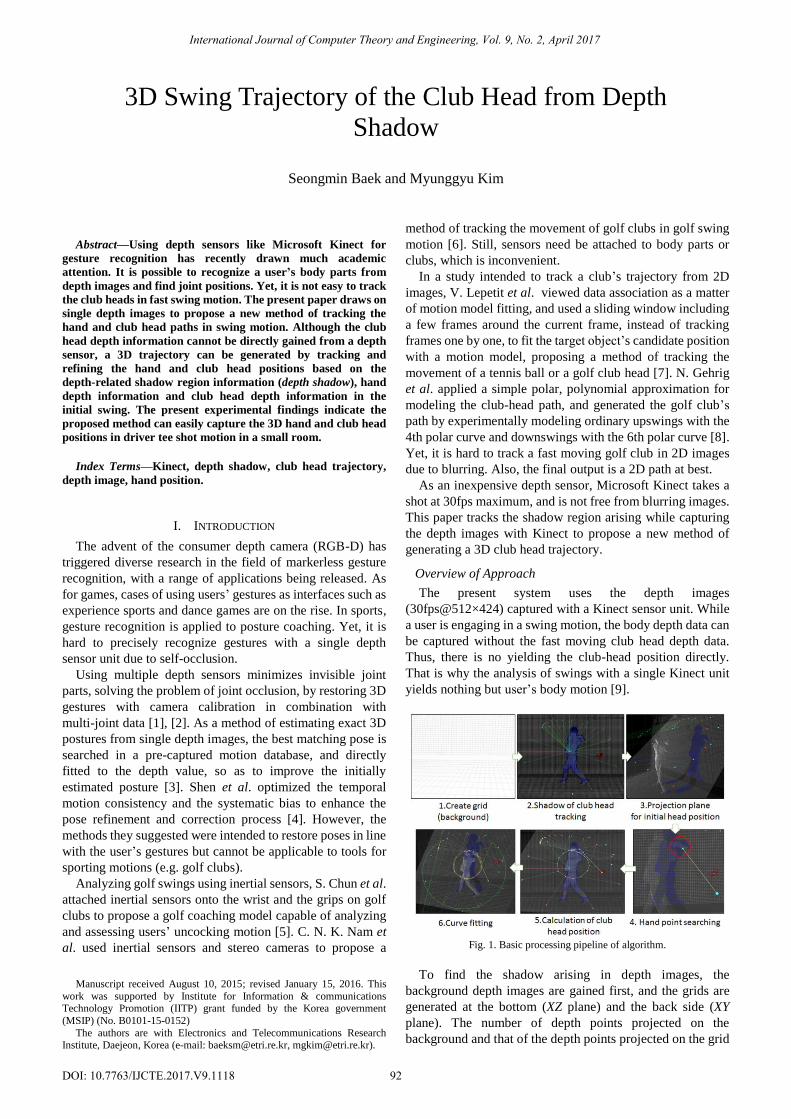
Overview of Approach
The present system uses the depth images
(30fps@512×424) captured with a Kinect sensor unit. While
a user is engaging in a swing motion, the body depth data can
be captured without the fast moving club head depth data.
Thus, there is no yielding the club-head position directly.
That is why the analysis of swings with a single Kinect unit
yields nothing but user’s body motion [9].
Fig. 1. Basic processing pipeline of algorithm.
To find the shadow arising in depth images, the
background depth images are gained first, and the grids are
generated at the bottom (XZ plane) and the back side (XY
plane). The number of depth points projected on the
background and that of the depth points projected on the grid
3D Swing Trajectory of the Club Head from Depth
Shadow
Seongmin Baek and Myunggyu Kim
International Journal of Computer Theory and Engineering, Vol. 9, No. 2, April 2017
92DOI: 10.7763/IJCTE.2017.V9.1118
in the swing motion are compared with each other to locate
the club-head shadow. Hand positions are estimated based on
the 3D initial club head position on the virtual swing plane.
Then, the 3D head position is calculated using the club
length. The hand position is refined in relation to the
club-head position and length. Finally, the spline curve is
used to restore the 3D hand and club head trajectories.
The prerequisites for the system include the plane as flat as
possible for capturing shadows and the wall behind the user.
Fig. 1 illustrates the entire process of estimating the
club-head and hand positions.
II. BACKGROUND REGISTRATION
With the captured depth images, the principal point and the
focal length provided in Kinect SDK are applied as in the
formula 1 and arranged in the 3D space (Fig. 2).
xyz
xyxyxyxyxy
DW
FDPIW
/)( (1)
Here, I is the value for a 2D image pixel. P is the principal
point. F is the focal length. D is the depth value. The points in
the 3D space are represented as Wxyz.
Background registration is intended to generate the
Grid(GX Z , GX Y) at the bottom (XZ plane) and the back side
(XY plane), and count the projected points. As noises
frequently occur at the top and bottom as well as on the left
and right sides of the depth images, the grid generation
should be limited to the region that captures the user’s
movement including the club, which reduces the noises and
shortens the calculation time.
The bottom grid generated is NX ×MZ, whilst the backside
grid is NX ×MY. Here, N and M are the number of grids and
determined by the grid sizes. When the grid size is too big,
the head’s shadow region can be missing, whereas when the
size is too small, the number of shadow regions to be
searched increases due to noises. Here, the size of 4×3 is set
to fit the head shadow size.
Fig. 2. Grid with projected points.
The position of the grid plane for projecting the 3D depth
points is determined by the average height of the bottom and
the average depth of the back side in the background.
Once the grid size and position are determined, the 3D
points are projected onto each grid. Then, the number of
projected points included within the grid (Nij, Nik) need be
counted.
The grid space including the points projected onto the
bottom and the back side is shown in Fig. 2.
Finally, the golf ball position (Pb) need be sought. As the
ball is placed in a fixed position, it is possible to get its depth
value, based on which its initial 3D position can be found
with ease. The ball’s initial position is used in chapter 4 to
make a projection plane.
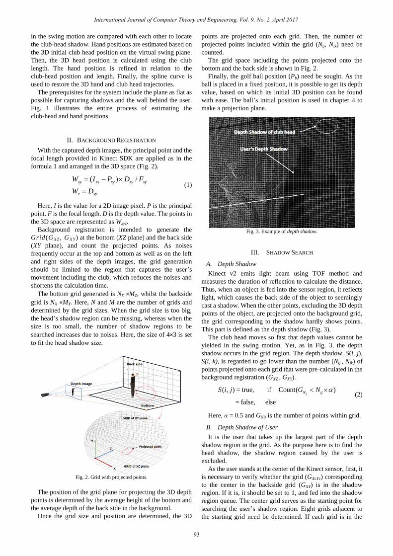
Fig. 3. Example of depth shadow.
III. SHADOW SEARCH
A. Depth Shadow
Kinect v2 emits light beam using TOF method and
measures the duration of reflection to calculate the distance.
Thus, when an object is fed into the sensor region, it reflects
light, which causes the back side of the object to seemingly
cast a shadow. When the other points, excluding the 3D depth
points of the object, are projected onto the background grid,
the grid corresponding to the shadow hardly shows points.
This part is defined as the depth shadow (Fig. 3).
The club head moves so fast that depth values cannot be
yielded in the swing motion. Yet, as in Fig. 3, the depth
shadow occurs in the grid region. The depth shadow, S(i, j),
S(i, k), is regarded to go lower than the number (Nij , Nik) of
points projected onto each grid that were pre-calculated in the
background registration (GXZ , GXY).
( , ) = true, if Count( )
= false, else
ijN ijS i j G N (2)
Here, α = 0.5 and GNij is the number of points within grid.
B. Depth Shadow of User
It is the user that takes up the largest part of the depth
shadow region in the grid. As the purpose here is to find the
head shadow, the shadow region caused by the user is
excluded.
As the user stands at the center of the Kinect sensor, first, it
is necessary to verify whether the grid (GXcYc) corresponding
to the center in the backside grid (GXY) is in the shadow
region. If it is, it should be set to 1, and fed into the shadow
region queue. The center grid serves as the starting point for
searching the user’s shadow region. Eight grids adjacent to
the starting grid need be determined. If each grid is in the
International Journal of Computer Theory and Engineering, Vol. 9, No. 2, April 2017
93

shadow region, it should be set to 1 and fed into the shadow
region queue. Each of the grids fed into the shadow region
queue need be taken out, in order to double check if the
adjacent grids not set to 1 are in the shadow region and save
them. This process need be repeated until the shadow region
queue becomes empty.
As for the starting point of the bottom grid (GXZ), the
region that is identical to the grid’s X-axis index value at the
point of meeting the back-side grid is fed into the queue as the
starting point (GXkZm-1 ← GXkYo = 1). Following the process
aforementioned, adjacent grids need be verified.
Fig. 4. Shadow region of user and club head.
Fig. 5. Virtual swing plane & initial 3d club head position.
Upon completion of the process, the shadow region caused
by the user is extracted. From the grid region excluding the
shadow region caused by the user (Gij ≠1), the shadow cast
by the club head is found. The following pseudo code shows
the process of searching the user’s depth shadow.
neighbor neighbor
neighbor
neighbor
neighbor
ShadowQueue.Add( ), if ( 1 )
for in ShadowQueue
for of , 1
if depth shadow
1
ShadowQueue.Add( )
C C C CX Y X Y
cur
cur
G G
G
G G G
G
G
G
(3)
C. Depth Shadow of Club Head
The depth map generated by Kinect may be mistaken for
the shadow region as the number included in the grid varies
with noises. Also, due to the fast swing speed of the club,
blurring occurs even in the shadow region, which makes it
hard to determine the exact position. In addition, the club
shaft may cast a shadow. Here, the purpose is to track the
parts corresponding to the head in several shadow regions
attributable to noises and other factors.
Following the above mentioned method, the depth shadow
should be found in the grid excluding the user region. The
shadow region found is subject to segmentation to generate a
block consisting of adjacent grids. If a single block is
generated, it is considered the head region. Yet, if more than
two blocks are formed, the head region should be found as
follows:
A block that takes up a significant number of grids in
comparison to other blocks; and
A block closer to the position predicted based on the
previous head shadow position and velocity.
When the initial swing is about to start, the head speed is 0.
Subsequently, up to 2~3 frames, the speed is not so fast that a
large shadow region cast by the head can be captured, making
it easy to find the head shadow region. Then, the current
position can be determined based on the previous position
and velocity.
Here, it is necessary to find out if the head’s depth data is
on the line that connects the starting point in the coordinate
system with the head shadow region’s central point. At the
very moment that the initial swing starts, or for a few frames
when the swing starts to move from the halt state, the head’s
depth data can be obtained.
The obtained head depth data is used to correct the
occluded hand position as well as the head’s 3D position.
IV. 3D TRAJECTORY
Based on the club head’s shadow region, this paper
proposes a straightforward method of tracking the 3D
positions of the club head and the hand.
The 3D head and hand positions are found as follows.
First, based on the club-head shadow region, a virtual swing
plane need be generated. Then, the club-head position should
be moved onto the virtual swing plane. The depth points close
to the estimated initial club-head position are found. The
selected depth points are assumed as the endpoint position of
the hand, from which the actual 3D club-head position is
sought. The hand position, which is inaccurate due to
occlusion, can be corrected based on the club-head position.
Details of each process are described below.
A. Virtual Swing Plane & Initial Club Head Position
A shadow cast in the background implies that the 3D head
position is present on the line connecting the starting point in
the camera’s coordinate system with the club head’s shadow
region. Still, it is not possible to establish the exact point on
the line as the head’s position. Thus, additional information is
needed. To that end, the user’s hand position is estimated.
Still, selecting the points closest to the head’s shadow region
may lead to mapping other parts, not the hand.
To track the exact hand position, a virtual swing plane is
defined here, given that the golf swing motion moves along
the downswing plane.
International Journal of Computer Theory and Engineering, Vol. 9, No. 2, April 2017
94

To generate the projection plane, the ball’s initial position
(Pb) and the club head shadow region of the highest y value
are used (Fig. 4).
max( )
(1, 0, 0)
Normal ( )
S Z h
X
P S X
V P C P
V
N V V
(4)
Here, Pmax is the position of the highest y value in the head
shadow region. CZ vector used to correct the depth value is a
value for approaching the range of the club’s movement. The
projection plane’s normal vector is Np.
The point where the line that connects the starting point in
the camera’s coordinate system with each head shadow
region meets the projection plane is set as the initial head
position (iHEt). Fig. 5 shows the generated virtual swing
plane and the initial head position.
(a) Hand point selection by initial head position and previous hand velocity
(b) Wrong point selection of hand by occlusion and the difference between
real depth point and calculation point of club head
(c) Hand position correction with hand velocity and club head depth data
Fig. 6. Hand position in the downswing.
The projection plane is intended for approximation to the
downswing plane so as to estimate the 3D position of the
user’s hand based on the initial club head position. Thus, if
not an exact head position, the hand position can be estimated
more accurately than seeking its position directly in the head
shadow region.
B. 3D Hand Position
As the depth information is gained from a single depth
sensor, the hand parts are occluded depending on the swing
time, which makes it difficult to find the endpoint position of
the hand grabbing the club. Hence, the point when the hand
position is most visible in the swing, or the point when the
head shadow position occurs on the XZ plane, is used as the
starting point for tracking the hand.
As the hand comes forward when the club is about to hit
the ball, a point closest to the initial club head position (iHEt)
is selected as the initial hand position (iHAt). Based on the
hand position and velocity calculated in the current frame (t
frame), the previous frame (t-1) is used to track the hand
position in the downswing, whilst the next frame (t+1) is used
to track the hand position in the upswing.
1 1
1 1
| |
| ( ) |
with shortest ( )
t t k t
t t t k
t k t
l iHE P
iHA Vh P
iHA P l
(5)
Despite being straightforward, the proposed method
proves to successfully track the endpoint position of the hand
in the experiment (Fig. 6(a)).
However, when the hand moves backward, it is not
possible to find the exact position of the hand due to
occlusion (Fig. 6(b)). If the hand position shows an
insignificant difference from the previous value, or if it
moves in a direction different from the expected one, the
estimated value is set as the initial hand position (Fig. 6(c)).
C. 3D Head Position
Based on the initial hand position tracked in every frame,
the 3D club-head position is tracked. It is assumed that the
club length, L, is already known. As above mentioned, the 3D
head position is present on the line that connects the starting
point in the coordinate system with the head shadow region.
Thus, it becomes a matter of finding the position on the line at
a distance of L from the initial hand position, which is easily
calculated with the second law of cosines.
)(
)cos(222
2
TOSHE
LHALHAT
C
(6)
Here, OSc is the vector that connects the starting point (O)
in the camera’s coordinate system with each head shadow
center (Sc).
As a rule, two solutions exist. Here, based on the previous
3D club head position and velocity, the closer point is chosen.
When the swing starts, the club’s depth value can be
yielded within the first 2~3 frames. This value becomes the
actual 3D head position and serves as the reference point for
International Journal of Computer Theory and Engineering, Vol. 9, No. 2, April 2017
95
Here, t+1 and t-1 refer to the upswing and the downswing
directions, respectively. Pk (k=1…n) is the 3D user depth
point. ωt is the weighted value, which is defined as the
distance between the position in line with the hand velocity
and the points.
the head position and velocity.
D. 3D Hand Position Refinement
Once the 3D club head position is determined, the club
length, L, is used again for the refinement of the initial hand
position because there may be a gap between the position at a
distance of L from the 3D head position toward the hand, and
the hand position. In particular, when the hand is occluded by
the head, the exact hand position is hard to find, leading to a
significant gap.
If the gap exceeds the threshold, the hand position is
refined to the position at a distance of L from the 3D
club-head position, which benefits the calculation of the hand
path. Notably, as the actual club-head depth data can be
gained in a couple of first frames, the hand position can be
refined based on such frames, which ensures a better
calculation.
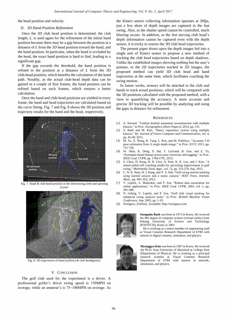
Once the hand and club-head positions are yielded in every
frame, the hand and head trajectories are calculated based on
the curve fitting. Fig. 7 and Fig. 8 shows the 3D position and
trajectory results for the hand and the head, respectively.
Fig. 7. Hand & club head position in the downswing (red) and upswing
(cyan).
Fig. 8. 3D trajectories of hand (yellow) & club head(green).
V. CONCLUSION
The golf club used for the experiment is a driver. A
professional golfer’s driver swing speed is 150MPH on
average, while an amateur’s is 75~100MPH on average. As
the Kinect sensor collecting information operates at 30fps,
just a few shots of depth images are captured in the fast
swing. Also, as the shutter speed cannot be controlled, much
blurring occurs. In addition, as the fast moving club head’s
depth information cannot be captured even with the depth
sensor, it is tricky to restore the 3D club head trajectories.
The present paper draws upon the depth images fed into a
single unit of Kinect sensor to propose a new method of
tracking the club head trajectories based on depth shadows.
Unlike the established images showing nothing but the user’s
posture, or the 2D trajectories tracked in 2D images, the
proposed method can yield 3D club head and hand
trajectories at the same time, which facilitates coaching the
swing motion.
In future works, sensors will be attached to the club and
hands to track actual positions, which will be compared with
the 3D positions calculated with the proposed method, with a
view to quantifying the accuracy. A more accurate and
precise 3D tracking will be possible by analyzing and using
the gaps in distance for refinement.
REFERENCES
[1] A. Naveed, “Unified skeletal animation reconstruction with multiple
kinects,” in Proc. Eurographics (Short Papers), 2014, pp. 5-8. [2] S. Baek and M. Kim, “Dance experience system using multiple
kinects,” Int. Journal of Future Computer and Communication, vol. 4,
pp. 45-49, 2015. [3] M. Ye, X. Wang, R. Yang, L. Ren, and M. Pollefeys, “Accurate 3-D
pose estimation from A single depth image,” in Proc. ICCV, 2011, pp.
731-738. [4] W. Shen, K. Deng, X. Bai, T. Leyvand, B. Guo, and Z. Tu,
“Exemplar-based human action pose correction and tagging,” in Proc.
IEEE Conf. CVPR, pp. 1784-1791, 2012. [5] S. Chun, D. Kang, H. R. Choi, A. Park, K. K. Lee, and J. Kim, “A
sensor-aided self coaching model for uncocking improvement in golf
swing,” Multimedia Tools Appl., vol. 72, pp. 253-279, Sep. 2013.
[6] C. N. K. Nam, H. J. Kang, and Y. S. Suh, “Golf swing motion tracking
using inertial sensors and a stereo camera,” IEEE Trans. Instrum. Meas., pp. 943–952, 2013.
[7] V. Lepetit, A. Shahrokni, and P. Fua, “Robust data association for
online applications,” in Proc. IEEE Conf. CVPR, 2003, vol. 1, pp. 281-288.
[8] N. Gehrig, V. Lepetit, and P. Fua, “Golf club visual tracking for
enhanced swing analysis tools,” in Proc. Brithsh Machine Vision Conference, Sep. 2003, pp. 1-10.
[9] Swinguru. [Online]. Available: http://swinguru.com
Seongmin Baek was born in 1973 in Korea. He received
the MS degree in computer science (virtual reality) from Pohang University of Science and Technology
(POSTECH), Korea in 2001.
He is working as a senior member of engineering staff at Visual Contents Research Department of ETRI with
interest in digital contents, animation, and physics.
Myunggyu Kim was born in 1967 in Korea. He received
the Ph.D. from University of Maryland at College Park
(Department of Physics). He is working as a principal research scientist at Visual Contents Research
Department of ETRI with interest in network,
simulation, and physics.
International Journal of Computer Theory and Engineering, Vol. 9, No. 2, April 2017
96