3D reconstruction system of H-7650 TEM for tomography and ...
6
3D reconstruction system of H-7650 TEM for tomography and its application to biological specimen Eiko Nakazawa, Mitsuo Ogasawa, Takafumi Yotsuji, Takahito Hashimoto Hitachi High-Technologies Corporation, Nanotechnology Products Business Group, Naka Division, Naka Application Center TEMs are one of the most useful devices to observe the fine structures of samples because their ultra-structures of some materials such as functional proteins and highly designed plastics would be closely related to their intrinsic natures, especially three dimensional structures of molecules would affect their functions. Therefore, the 3D structure of samples might be a key point to investigate their functions. TEM images are formed as 2D projections but they include the 3D information in their contents. TEM tomography recently attracts a great deal of considerable attention as a notable technique to gain the 3D information, in which serially tilted images are reconstructed by back-projection. The 3D reconstruction system of model H-7650 TEM is developed for TEM tomography. The system is composed of automatic image capturing function of serially tilted images and reconstruction software. New algorithm is adopted especially to avoid image artifact due to the missing zone of specimen stage tilting range. The general features of the 3D reconstruction system for the H-7650 and its applications to biological specimens are introduced in this study. 【General features of 3D reconstruction system of H-7650 TEM】 The 3D reconstruction system of H-7650 are composed with the automatic specimen tilting function and the reconstruction software FIG.1 General view of Hitachi 120kV TEM model H-7650 equipped with 3Dreconstruction system mentioned above. The general view of model H-7650 TEM equipped with the 3D reconstruction system is shown in FIG.1. (1) Automatic functions for specimen tilting and image capturing In this system, the eucentric goniometer stage can automatically tilt ranging in +/- 60 degrees with 0.5-degree step, minimally. The shifts of imaging position and focus during specimen tilt can be measured from TEM images and automatically 1
Transcript of 3D reconstruction system of H-7650 TEM for tomography and ...
3D reconstruction system of H-7650 TEM for tomography and its application to biological specimen
Eiko Nakazawa, Mitsuo Ogasawa, Takafumi Yotsuji, Takahito Hashimoto
Hitachi High-Technologies Corporation, Nanotechnology Products Business Group,
Naka Division, Naka Application Center
TEMs are one of the most useful devices to observe the fine structures of samples
because their ultra-structures of some materials such as functional proteins and highly
designed plastics would be closely related to their intrinsic natures, especially three
dimensional structures of molecules would affect their functions. Therefore, the 3D structure
of samples might be a key point to investigate their functions. TEM images are formed as 2D
projections but they include the 3D information in their contents. TEM tomography recently
attracts a great deal of considerable attention as a notable technique to gain the 3D
information, in which serially tilted images are reconstructed by back-projection. The 3D
reconstruction system of model H-7650 TEM is developed for TEM tomography. The system
is composed of automatic image capturing function of serially tilted images and
reconstruction software. New algorithm is adopted especially to avoid image artifact due to
the missing zone of specimen stage tilting range. The general features of the 3D
reconstruction system for the H-7650 and its applications to biological specimens are
introduced in this study.
【General features of 3D reconstruction system of H-7650 TEM】
The 3D reconstruction system of H-7650 are composed with the automatic specimen
tilting function and the reconstruction software
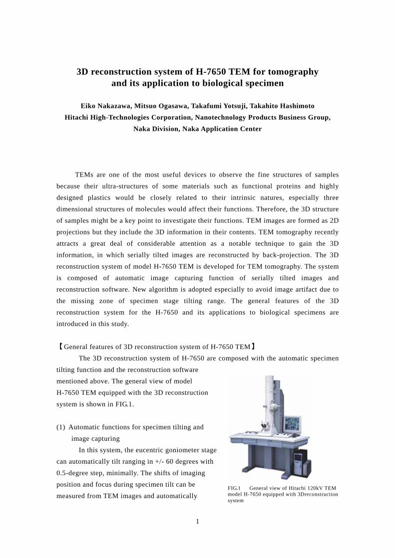
FIG.1 General view of Hitachi 120kV TEM model H-7650 equipped with 3Dreconstruction system
mentioned above. The general view of model
H-7650 TEM equipped with the 3D reconstruction
system is shown in FIG.1.
(1) Automatic functions for specimen tilting and
image capturing
In this system, the eucentric goniometer stage
can automatically tilt ranging in +/- 60 degrees with
0.5-degree step, minimally. The shifts of imaging
position and focus during specimen tilt can be
measured from TEM images and automatically
1

corrected with feedback control system based on the phase only correlation technique. Whole
process, sequential movements of stage tilt and image capturing with a slow scan CCD
camera, is automatically performed. Especially, in H-7650 TEM, the height of specimen stage
during the tilt of specimen is not necessary to adjust because automatic focusing function
works during the sequence and magnification error is restricted within +/- 0.5 % in the range
of +/- 60 deg tilt angles. Furthermore, preliminary marking on specimens with colloidal gold
particles for positioning is not needed because of the precise specimen position alignment by
the image correlation and corresponding point techniques similar with the particle marking
procedure.
(2) 3D reconstruction software
Serially tilted images are processed with some algorithms for reconstruction. To make
a precise tomogram, the object should be rotated at 360 degrees and all the projections of the
wholly rotated object similar with the images by an X-ray CT scanner should be processed for
an ideal TEM tomography. However, the serially tilted images for TEM tomography could
not be perfect because the missing zone of specimen tilting angles due to the mechanical
limitation remains and the missing zone causes artifact on their reconstruction result and
finally reduces the quality of reconstruction. Especially, in case of samples mounted on grids
the quality of reconstruction would be extremely deteriorated without the side view of
specimens. To resolve these problems, we have newly developed the reconstruction algorithm
named Topography-based reconstruction (TBR) technique collaborating with Professor
Eisaku Katayama of the University of Tokyo and Professor Norio Baba of Kogakuin
University1, 2). In this algorithm, after precise axial alignment of all the tilt-series images,
topographic profiles of the specimen are estimated by stereo-photogrammetry of each
corresponding point along the cross section. Next, the density distribution of the image along
that section is converted to the thickness value and used as the initial approximation of the
subsequent calculations. Then the thickness distribution is modified so that all the density
distribution in each image satisfies the simultaneous equations by iterative calculation
process until the solution. Especially, the reconstruction technique applied to replica samples
is named Dynamic shell modeling, DSM for short. The topography-based reconstruction
method enables us to avoid serious effect of missing zone due to mechanical limitation of
specimen tilt angles, which seriously deteriorates the quality of the reconstructed images. The
reconstructed image is displayed with volume rendering or multilateral slice in this system.
【Applications】
FIG.2 shows the reconstructed images of the quick frozen deep etched replica of
bovine cerebellum by the Dynamic Shell Modeling technique (DSM) and the simultaneous
iterative reconstruction technique (SIRT). Presently, the SIRT is one of the most precise
2
techniques among conventional reconstruction algorithms.
As shown in FIG.2A and 2B, both of the slice views at 0 degree are almost equal.
However, slices of the side view obtained with the DSM shown in FIG.2C is clearly dissimilar
to that taken with the SIRT shown in FIG.2D. The side view of the tomogram by the DSM is
clearly seen without the blurriness and fine structures of the replica are recognized in the
cross section in FIG2E. On the other hand, the side view reconstructed by the SIRT is blurred
and the white stretched artifacts overlapped the reconstruction result, in which fine structures
of the replica can not be recognized as shown in FIG.2F. This phenomenon is caused by the
missing zone due to the mechanical limitation of stage tilting angles. Furthermore, the slices
perpendicular to the tilting axis of the reconstructed image indicate in FIG.2E and 2F. Similar
to the side views of the reconstructed images, the slice by the SIRT shows the long stretched
line and the discontinuity of the cross section in FIG.2F. The slice by the DSM was indicated
as a clear and continuous line in FIG.2E.
The results of reconstruction are displayed on the 3D Viewer in this system as shown
in FIG.3, in which a volume rendering and slices of the multiple projection can be displayed
and also a distance between any two points can be measured. Especially, the reduction of the
artifact due to the mechanical limitation of tilting angles is indispensable to 3D measurements
and quantitative analysis of the tomogram.
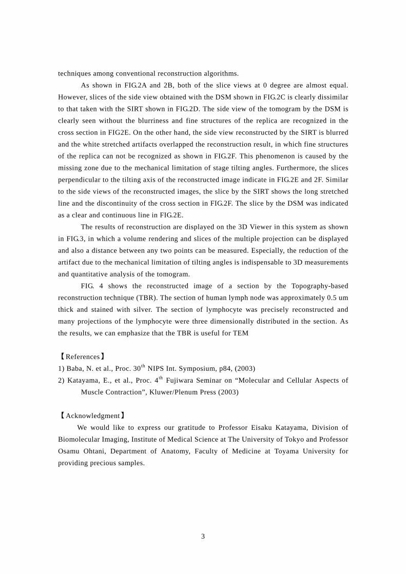
FIG. 4 shows the reconstructed image of a section by the Topography-based
reconstruction technique (TBR). The section of human lymph node was approximately 0.5 um
thick and stained with silver. The section of lymphocyte was precisely reconstructed and
many projections of the lymphocyte were three dimensionally distributed in the section. As
the results, we can emphasize that the TBR is useful for TEM
【References】 1) Baba, N. et al., Proc. 30th NIPS Int. Symposium, p84, (2003)
2) Katayama, E., et al., Proc. 4th Fujiwara Seminar on “Molecular and Cellular Aspects of
Muscle Contraction”, Kluwer/Plenum Press (2003)
【Acknowledgment】 We would like to express our gratitude to Professor Eisaku Katayama, Division of
Biomolecular Imaging, Institute of Medical Science at The University of Tokyo and Professor
Osamu Ohtani, Department of Anatomy, Faculty of Medicine at Toyama University for
providing precious samples.
3

A B
E F
C D
500 nm
FIG.2 Comparison of the tomograms between the DSM and SIRT methods
(A,B) Volume rendering parallel to tilting axis (0degree) (A; DSM, B; SIRT) (C,D) Side views of tomograms ( C; DSM, D; SIRT) (E,F) Slices perpendicular to tilting axis (X-Y plane) (E; DSM, F; SIRT)
Specimen: Quick frozen deep etched replica of rat cerebellum Magnification:3,500 x, Acc.,Volt.: 100 kV Range of tilting angles: +60 to –57 degrees., Tilting steps: 3 degrees (Courtesy of Professor Eisaku Katayama at The University of Tokyo)
4

BA
B
FIG.3 T ( ( ( S M R
C
hree dimensional indication of the tomogram reconstructed by thA) Graphical user interface of 3D Viewer B) Three dimensional display of the reconstruction results C) Multiple slices indicated in FIG.3B with a blue mesh pecimen: Quick frozen deep etched replica of rat cerebellum agnification:3,500 x, Acc.,Volt.: 100 kV ange of tilting angles: +60 to –57 degrees., Tilting steps: 3 d(Courtesy of Professor Eisaku Katayama at The University of To
5
e DSM
egrees kyo)

FIG.4 Tomogram of human lymphocyte section reconstructed by the TBR method Specimen: human lymph node stained with silver Magnification:4,000 x, Acc.,Volt.: 120 kV Range of tilting angles: +/ 60 degrees., Tilting steps: 2 degrees (Courtesy of Professor Osamu Ohtani at Toyama University)
6