3D-PRINTED TITANIUM IMPLANTS WITH TITANIA NANOTUBES: …
65
3D-PRINTED TITANIUM IMPLANTS WITH TITANIA NANOTUBES: DUAL-SCALE TOPOGRAPHY FOR BONE APPLICATIONS By CHIARA MICHELETTI, B.Eng. A Thesis Submitted to the School of Graduate Studies in Partial Fulfilment of the Requirements for the Degree of Master of Applied Science McMaster University © Copyright by Chiara Micheletti, August 2018
Transcript of 3D-PRINTED TITANIUM IMPLANTS WITH TITANIA NANOTUBES: …

3D-PRINTED TITANIUM IMPLANTS WITH
TITANIA NANOTUBES: DUAL-SCALE
TOPOGRAPHY FOR BONE APPLICATIONS
By CHIARA MICHELETTI, B.Eng.
A Thesis Submitted to the School of Graduate Studies in Partial Fulfilment of
the Requirements for the Degree of Master of Applied Science
McMaster University © Copyright by Chiara Micheletti, August 2018

M.A.Sc. Thesis - C. Micheletti; McMaster University - Materials Science and Engineering
ii
MASTER OF APPLIED SCIENCE (2018), Materials Science and Engineering
McMaster University, Hamilton, Ontario, Canada
TITLE: 3D-printed titanium implants with titania nanotubes: dual-scale topography for bone
applications
AUTHOR: Chiara Micheletti, B.Eng. (Università degli Studi di Brescia, Italy)
SUPERVISOR: Dr. Kathryn Grandfield
NUMBER OF PAGES: xv, 50

M.A.Sc. Thesis - C. Micheletti; McMaster University - Materials Science and Engineering
iii
Lay Abstract
Bone implants are often made of titanium-based materials, which, despite their suitable
properties, may not sufficiently bond with the living bone tissue. This can lead to implant
loosening and failure. To produce customized implants, additive manufacturing, or 3D-
printing, can be employed. However, these surfaces require substantial post-processing to
produce features capable of promoting bone integration. In this work, a dual-scale surface
topography to combine the advantages of both micro- and nanoscale roughness was created
using electrochemical anodization on 3D-printed titanium alloy substrates. Preliminary
physical, chemical, and biological characterizations suggest that the creation of titania
nanotubes on the 3D-printed surfaces of Ti-6Al-4V and Ti-5Al-5Mo-5V-3Cr could improve
their ability to bond with bone.

M.A.Sc. Thesis - C. Micheletti; McMaster University - Materials Science and Engineering
iv
Abstract
Bone implants procedures involve millions of people every year worldwide. One of the main
factors determining implant success is related to the ability of the prostheses to osseointegrate,
i.e. to create a structural and functional connection with the living bone [1].
Titanium and titanium alloys are widely used biomaterials for bone implants, due to their
superior biocompatibility and corrosion resistance, suitable mechanical properties, and natural
ability to osseointegrate [2]. To further enhance the inherent tendency of this class of materials
to bond with the host bone tissue, the surface of Ti-based implant is often modified to improve
cell responses in terms of adhesion, proliferation and differentiation, all factors contributing to
successful osseointegration. In particular, surface topography, both at the micro- and nanoscale,
can enhance the implant-living bone interaction [3].
Herein, a possible surface modification strategy aimed at the creation of a dual-scale
topography on two different titanium alloys, Ti-6Al-4V and Ti-5Al-5Mo-5V-3Cr, is presented.
Dual-scale topography was obtained by electrochemically anodizing samples manufactured by
selective laser melting to combine their intrinsic microtopography with the nanotopography
offered by titanium dioxide nanotubes (TNTs) generated by anodization. Characterization of
the as-printed and as-anodized samples was performed to evaluate parameters of significance
in the context of osseointegration. Concerning wettability, it was observed that surfaces with
TNTs exhibited high hydrophilicity. The influence of the anodization process parameters on
TNTs morphology was examined, and linear dependence of the nanotube diameter on the
voltage was identified. Annealing of the as-anodized samples showed that anatase was
produced, while preserving the nanotube integrity. Preliminary studies to assess the bioactive
properties of the samples showed the spreading of bone-like cells on these substrates and the
deposition of mineral during simulated body fluid testing. Therefore, both studies provided
promising results to corroborate the hypothesis that dual-scale topography could potentially
improve osseointegration.

M.A.Sc. Thesis - C. Micheletti; McMaster University - Materials Science and Engineering
v
Acknowledgements
I had the incredible opportunity to join a double degree program between McMaster University
(Canada) and Politecnico di Milano (Italy), an experience I will be always grateful for. The
research work presented in this thesis and my year in Canada would have not been the same
without contribution of the following people.
First and foremost, I would like to thank my supervisor, Dr. Kathryn Grandfield, for her
invaluable guidance and support. Thank you for being a great example of the passionate interest
and curiosity that move scientific research and discovery, and for showing me a new side of
the engineering world.
I would also like to express my gratitude to all the members of the Grandfield Research Group,
for the welcoming atmosphere I have been surrounded by since my arrival. Thank you for all
the time spent together, and all the experiences we lived, from building dragons to getting
addicted to card games. In particular, many thanks to Bryan, for his troubleshooting skills, all
the cell culturing work, and for sharing his incredibly vast knowledge of biomaterials with me.
I would like to extend a big thanks to Dakota, for the SEM sessions on the Magellan and for
being my main microscopy consultant, not mentioning being the main promoter of every highly
typical Canadian experience I lived. Thank you also to Ariana and Asad for their help at MARC
and their contribution to this work.
A special acknowledgement to those who played a significant role in my research, especially
Simon Coulson for the 3D-printing side of the project, Dr. Beth McNally for her support at
MARC, and the CCEM staff for microscopy and sample preparation assistance.
I also want to sincerely thank everyone who made my year abroad so unique. To the occupants
of JHE A406, because no matter the difficulties in reaching the 4th floor, the temperature swing
and the fire alarm, I could have never asked for a better working environment. To my
housemates, for simply being amazing and for all the hours spent chatting, which significantly
contributed to broaden my (slangs) knowledge of English. Thank you to everyone who made
me feel at home here in Canada.
Last but not least, my deepest gratitude goes to my family, for always being by my side, even
with an ocean in between us. Everything I had the opportunity to experience and achieve in
life, I owe it to you. Thank you especially for teaching me that “Roots are important in a
person’s life, but people have legs, not roots, and legs are meant to make you go elsewhere”.
M.A.Sc. Thesis - C. Micheletti; McMaster University - Materials Science and Engineering
vi
Table of Contents
Lay Abstract iii
Abstract iv
Acknowledgements v
Table of Contents vi
List of Figures ix
List of Tables xiii
List of Abbreviations xiv
Declaration of Academic Achievement xv
1. Introduction 1
1.1 Research motivation 1
1.2 Research objectives and hypotheses 2
2. Background 3
2.1 Bone implant materials 3
2.1.1 Biomaterial: requirements 3
2.1.1.1 Biocompatibility 3
2.1.1.2 Mechanical properties 3
2.1.1.3 Wear and corrosion resistance 4
2.1.1.4 Osseointegration 4
2.1.2 Titanium and titanium alloys 4
2.1.2.1 Titanium-bone interface 5
2.2 Additive manufacturing: selective laser melting 6
2.2.1 Characteristics and biomedical applications 6
2.2.2 Selective laser melting 7
2.2.2.1 Powder bed fusion systems 7
2.2.2.2 Process parameters and characteristics 7

M.A.Sc. Thesis - C. Micheletti; McMaster University - Materials Science and Engineering
vii
2.2.2.3 Surface topography 8
2.3 Osseointegration and surface topography 10
2.3.1 Importance of the implant surface 10
2.3.2 Surface topography 10
2.3.2.1 Microscale topography 10
2.3.2.2 Nanoscale topography 11
2.3.3 Aim of surface modification and possible strategies 11
2.4 Electrochemical anodization and TiO2 nanotubes 13
2.4.1 Anodization process 13
2.4.2 Factors influencing nanotubes morphology 14
2.4.2.1 Electrolyte 15
2.4.2.2 Applied voltage 15
2.4.2.3 Anodization time 15
2.4.3 TiO2 nanotubes and surface modification of bone implants 16
3. Materials and Methods 17
3.1 Samples manufacturing 17
3.2 Anodization 18
3.2.1 Annealing 19
3.3 Characterization 20
3.3.1 Surface characterization 20
3.3.1.1 Morphology and topography 20
3.3.1.2 Roughness 21
3.3.1.3 Wettability 21
3.3.1.4 Phase analysis 21
3.3.2 Biological characterization 21
3.3.2.1 Cell imaging 21
3.3.2.2 Bioactivity 22

M.A.Sc. Thesis - C. Micheletti; McMaster University - Materials Science and Engineering
viii
4. Results 23
4.1 3D-printed samples: microscale topography 23
4.1.1 Morphology and topography 23
4.1.2 Roughness 24
4.1.3 Wettability 25
4.1.4 Cell imaging 26
4.1.5 Bioactivity 27
4.2 Anodized samples: dual-scale topography 28
4.2.1 Morphology and topography 28
4.2.1.1 Anodization at constant voltage 28
4.2.1.2 Influence of voltage on TNTs diameter 31
4.2.1.3 Influence of time on TNTs morphology 34
4.2.1.4 Anodization with initial stepwise increase of voltage 36
4.2.2 Wettability 37
4.2.3 Annealing 38
4.2.4 Cell imaging 39
4.2.5 Bioactivity 40
5. Discussion 42
6. Conclusions 45
6.1 Summary of major findings 45
6.2 Limitations and future directions 46
References 47

M.A.Sc. Thesis - C. Micheletti; McMaster University - Materials Science and Engineering
ix
List of Figures
Figure 2.1 Schematic illustration of a generic powder bed fusion system. Reproduced from
[22] with permission. 8
Figure 2.2 SEM image showing the characteristic microspherical particles arranged on the
surface of a Ti-6Al-4V substrate obtained by SLM. 9
Figure 2.3 SEM micrographs of the surface of a titanium implant subjected to laser
modification to create micro- and nanoscale irregularities. A: The border between as-machined
surface and laser-modified surface. B: Higher magnification of the laser-modified surface.
Reproduced from [40] with permission. 12
Figure 2.4 A: Electrochemical cell with a two-electrode set up, with platinum as the cathode
and titanium as the anode. B: Reactions occurring at the Ti anode leading to the formation of
an array of TiO2 nanotubes: first a compact oxide is formed on Ti surface, then F- ions in the
solution start etching this layer and tubular structures are created. 14
Figure 2.5 SEM images of (a) top side, (b) bottom side, (c) cross-section of a TNTs array
obtained in an electrolyte comprised of 0.3 wt.% NH4F and 2 vol.% H2O in ethylene glycol at
60 V. Reproduced from [46] with permission. 15
Figure 3.1 2D drawing of the geometry of the samples manufactured by SLM. The area of
interest (square) is coloured in blue, the holder (rectangle) in yellow. The sample were 3D-
printed with a thickness (not visible in the 2D view) equal to 1 mm. 17
Figure 3.2 Trend of the applied anodization voltage as a function of time, and inset section to
better illustrate the initial stepwise increase. 19
Figure 3.3 Example of an SEM micrograph as-acquired (left) and after a threshold was applied
using ImageJ to obtain a binary image and identify the TNTs as ellipsoids (right). 21
Figure 4.1 SEM micrographs of as-printed Ti64 (left) and Ti5553 (right) samples. In both
cases, the surface is randomly covered with microspherical particles, which are characteristic
of the SLM manufacturing process. 23
Figure 4.2 Left: SEM micrograph of an as-printed Ti64 sample showing the size of some
microparticles on the surface. Right: Chart of the size distribution of the microspherical
particles in both Ti64 and Ti5553. Data were obtained analyzing a 350 μm x 350 μm area from
a SEM micrograph per alloy and measuring 30 particles in total. 24

M.A.Sc. Thesis - C. Micheletti; McMaster University - Materials Science and Engineering
x
Figure 4.3 2D (left) and 3D (right) views of the surface of a Ti64 sample manufactured by
SLM. 25
Figure 4.4 2D (left) and 3D (right) views of the surface of a Ti5553 sample manufactured by
SLM. 25
Figure 4.5 SEM micrographs showing bone-like cells adhering on a 3D-printed Ti64 sample.
Cells are present both in the flatter areas and stretching from the flatter regions to the
microspherical particles. In particular, micrograph C shows a significantly elongated cell
anchoring its filopodia onto a microsphere. 26
Figure 4.6 SEM micrographs showing bone-like cells adhering on a 3D-printed Ti5553
sample. As in case of Ti64 (Figure 4.5), cells are anchored both to the flatter areas and to the
microspherical particles. In particular, a cell adhering on a microparticle is visible in
micrograph C. 26
Figure 4.7 SEM image showing some precipitates on the surface of a Ti5553 sample immersed
in Hanks’ solution for 7 days, and its correspondent EDS analysis. Peaks relative to Ca, K, Cl
and P are distinguishable in the EDS spectrum. 27
Figure 4.8 Top (left) and bottom (right) views of TNTs. Left and right images correspond to a
Ti64 sample anodized for 30 minutes at 60 V and 40 V, respectively. 28
Figure 4.9 Left: Cracks visible on the surface on an anodized Ti64 sample (anodization at 60 V
for 30 minutes), in particular across the microspherical particles. Right: Higher magnification
image showing TNTs arrays separated by cracks on a microparticle. 29
Figure 4.10 Left: Microspherical particle on an anodized Ti64 sample (anodization at 40 V for
30 minutes) with a missing TNTs array, whose detachment may have been promoted by the
presence of cracks. Right: Higher magnification image showing a side-view of the TNTs. The
barrier layer, i.e. a layer of amorphous TiO2 that forms in between the substrate and the TNTs
[49], is also visible. 29
Figure 4.11 SEM image of a Ti64 sample anodized at 80 V for 30 minutes, in which it is visible
how several TNTs collapsed and merged into each other forming nanograss. 30
Figure 4.12 Example of anomalous TNTs obtained by anodizing Ti5553 at 60 V for 30
minutes. Nanotubes seems to have a double wall, and extended regions of nanograss are
present. 31

M.A.Sc. Thesis - C. Micheletti; McMaster University - Materials Science and Engineering
xi
Figure 4.13 SEM images of TNTs generated by anodization of Ti64 for 30 minutes at 20 V
(A), 40 V (B), 60 V (C) and 80 V (D). 32
Figure 4.14 SEM images of TNTs generated by anodization of Ti5553 for 30 minutes at 20 V
(A), 40 V (B), 60 V (C) and 80 V (D). 32
Figure 4.15 Graphs showing the variation in TNTs diameter as a function of the anodization
voltage for both Ti64 and Ti5553. 34
Figure 4.16 Morphology of TNTs on Ti64 anodized at 40 V for 5 (A), 10 (B), 20 (C) and 60
(D) minutes. 35
Figure 4.17 Morphology of TNTs on Ti5553 anodized at 40 V for 5 (A), 10 (B), 20 (C) and
60 (D) minutes. 36
Figure 4.18 TNTs obtained on Ti64 (left) and Ti5553 (right) by applying an initial stepwise
increase of voltage. 37
Figure 4.19 Water droplet behaviour on as-printed Ti64 (left) and after anodization at 40 V for
30 minutes (right). The anodized sample showed higher hydrophilicity, as can be inferred by
the significant spreading of water (right). A similar behaviour was observed for different
anodization voltages and for Ti5553 as well. 38
Figure 4.20 TNTs on Ti64 (left) and Ti5553 (right) anodized at 40 V for 30 minutes and then
annealed in open air at 500 °C for 2 hours. 38
Figure 4.21 XRD spectrum of an anodized and annealed Ti64 sample. Peaks identified by
green lines correspond to anatase. Red lines indicate titanium, most likely from the substrate
underneath the TNTs film. 39
Figure 4.22 XRD spectrum of an anodized and annealed Ti5553 sample. Peaks identified by
green lines correspond to anatase. Red lines indicate titanium, most likely from the substrate
underneath the TNTs film. A compound of titanium-vanadium-chromium (0.7Ti-0.1V-0.2Cr)
was also detected (peaks marked by blue lines). 39
Figure 4.23 SEM micrograph showing cell filopodia interacting with TNTs on the surface of
anodized Ti64 (left) and Ti5553 (right) samples. 40
Figure 4.24 Left: Cell on a flat area of an anodized Ti5553 sample. Right: Cell adhering both
on some microparticles and on a flat region of an anodized Ti64 sample. 40

M.A.Sc. Thesis - C. Micheletti; McMaster University - Materials Science and Engineering
xii
Figure 4.25 EDS spectrum and SEM image of an anodized Ti64 sample immersed in Hanks’
solution for 3 days. Precipitates of Ca, P, Na and K and P are visible, and it seems that they
filled the TNTs, as nanotubes pores are no longer noticeable on the surface. 41

M.A.Sc. Thesis - C. Micheletti; McMaster University - Materials Science and Engineering
xiii
List of Tables
Table 2.1 Mechanical properties of some titanium alloys [16]. For the sake of comparison,
typical mechanical properties of bone are also included. 5
Table 4.1 Values of 2D and 3D roughness parameters of as-printed Ti64 and Ti5553 samples.
24
Table 4.2 Contact angle (CA) values measured for as-printed Ti64 and Ti5553 samples. 25
Table 4.3 Mean diameter of TNTs generated by anodization of Ti64 and Ti5553 for 30 minutes
at four different voltages. 33
Table 4.4 Mean values of water contact angles (CA) obtained for both Ti64 and Ti5553 at four
different anodization voltages (20, 40, 60 and 80 V). 37

M.A.Sc. Thesis - C. Micheletti; McMaster University - Materials Science and Engineering
xiv
List of Abbreviations
AM: additive manufacturing
CA: contact angle
ECM: extracellular matrix
EDS: energy dispersive spectroscopy
HA: hydroxyapatite
Saos-2: sarcoma osteogenic
SBF: simulated body fluid
SEM: scanning electron microscopy
SLM: selective laser melting
Ti5553: Ti-5Al-5Mo-5V-3Cr
Ti64: Ti-6Al-4V
TNT: titania nanotube
XRD: x-ray diffraction

M.A.Sc. Thesis - C. Micheletti; McMaster University - Materials Science and Engineering
xv
Declaration of Academic Achievement
I hereby declare to be the sole author of this document. The research work presented in this
thesis was mostly completed by myself, with the contribution of people and institutions listed
below.
- 3D-printed samples of Ti64 and Ti5553 were manufactured by staff at the Additive
Manufacturing Innovation Centre at Mohawk Collage (Hamilton, ON, Canada) under the
direction of Simon Coulson.
- Imaging using the FEI Magellan 400 scanning electron microscope was done by Dakota
Binkley.
- Cell culturing of the as-printed and as-anodized samples was carried out by Bryan Lee.
- Coating of samples prior SEM imaging was completed by staff at the Canadian Centre of
Electron Microscopy at McMaster University (Hamilton, ON, Canada).
- Roughness measurements using Alicona Infinite Focus were done by associates at the
McMaster Manufacturing Research Institute at McMaster University (Hamilton, ON,
Canada).
- XRD characterization was carried out by staff at the McMaster Analytical X-ray
Diffraction Facility at McMaster University (Hamilton, ON, Canada).

M.A.Sc. Thesis - C. Micheletti; McMaster University - Materials Science and Engineering
1
1. Introduction
1.1 Research motivation
Bones can become damaged and weakened by age, accidents or disease. When this occurs, the
failed bone tissue needs to be replaced by an artificial implant, i.e. a bone implant or scaffold.
A high number of implant surgeries take place: considering only the US, 1-2 million of dental
implants and about 600,000 artificial hips and knees are annually implanted [4]. Moreover, the
demand for bone implants is expected to continually increase in coming years due to the aging
population. For example, statistics estimate that the total number of total hip replacements and
knee arthroplasties will rise by 174% and 673%, respectively, by 2030 [5]. Furthermore, not
only the number of initial surgeries has grown in the past years, but also that of revision
surgeries, i.e. additional surgeries required in case of failure of the implant placed in the first
operation.
Although the majority of bone implant procedures are successful, a non-negligible percentage
of bone implants is still prone to fail, approximately 5-10% of dental implants and 7% of total
joint replacements [4]. The two main causes of implant failure are aseptic loosening and
infection. In regard to the former, failure is often originated by poor osseointegration, i.e. a lack
of connection between the bone tissue and the implant surface [6]. Osseointegration is one of
the main factors determining implant success, thus it is a paramount aspect to consider in the
design of an implant (Section 2.3).
Presently, the vast majority of implants are made of metallic biomaterials [7], in particular
titanium and its alloys (Section 2.1). In fact, their superior biocompatibility, high corrosion
resistance and suitable mechanical properties make this class of materials ideal candidates for
bone implants. Moreover, titanium shows a natural ability to osseointegrate, allowing for bone
growth close to the implant surface [2]. However, implants made of titanium usually undergo
some surface treatments or modifications to ensure a superior bonding to the host bone tissue
and reduce the risk of implant loosening and failure [8]. In particular, it has been shown that
there is a direct relationship between osseointegration and surface topography, therefore
surface modification of Ti-based implants usually aims to create suitable topographical features
[3]. A promising alternative is the creation of titanium dioxide nanotubes by electrochemical

M.A.Sc. Thesis - C. Micheletti; McMaster University - Materials Science and Engineering
2
anodization (Section 2.4), as nanoscale surface topography is believed to promote
osseointegration [9].
1.2 Research objectives and hypotheses
The main objective of the present research was to enhance the surface properties of 3D-printed
titanium alloys to create dual topography surfaces that could be more favourable for
osseointegration. The specific aims of this thesis include:
1. To modify the surface of two different 3D-printed titanium alloys (Ti-6Al-4V and Ti-5Al-
5Mo-5V-3Cr) by electrochemical anodization to create titanium dioxide nanotubes on
microrough surfaces. The goal was to create a dual-scale surface topography by combining
the microtopography of the 3D-printed samples with the nanoscale features obtained by
anodization to take advantage of both micro- and nanotopography to improve cellular
responses, and ultimately improve the osseointegration of Ti-based bone implants.
2. To investigate the influence of different anodization and annealing conditions on the
morphology of 3D-printed substrates and resultant surfaces.
3. To perform comprehensive surface characterization to assess the potential role of the
modified surfaces on osseointegration. This was achieved by analyzing morphology and
topography, both before and after anodization, mainly using scanning electron microscopy,
and evaluation of surface roughness and wettability. In addition, preliminary biological
cell-surface interaction and bioactivity characterizations were carried out.
It was hypothesized that the substrates with a dual-scale topography would show encouraging
bioactive properties in terms of cell response and mineral deposition.
M.A.Sc. Thesis - C. Micheletti; McMaster University - Materials Science and Engineering
3
2. Background
2.1 Bone implant materials
Damaged bone tissue is usually surgically substituted with an artificial replacement to restore
its functionality. When designing a bone implant, selection of the right material is paramount
to ensure the success of the implant itself. Requirements that need to be satisfied concern
biocompatibility, high corrosion and wear resistance, suitable mechanical properties and
osseointegration [10].
2.1.1 Biomaterial: requirements
2.1.1.1 Biocompatibility
Biocompatibility is a fundamental property that materials placed in contact with living tissues
and organs need to exhibit. When a material is biocompatible, it can more specifically be
referred to as “biomaterial”. A material is defined as biocompatible when it does not cause any
harmful effects to the body [11]. When a material is implanted in the body, its interaction with
body fluids, proteins and cells produces a series of reactions that determines whether or not it
is accepted by the host system without causing inflammatory or allergic reactions [12]. The
main issues regarding biocompatibility are thrombosis and fibrous tissue encapsulation of the
implant [13]. The biomaterial surface plays a major role in determining how the body will
respond to the implant, as it is the first point of contact between the implant and the host. In
addition, to evaluate the overall biocompatibility of an implant, it is important to consider all
the elements constituting it, since they could be released into the human body due to wear or
corrosion and potentially cause adverse effects [7].
2.1.1.2 Mechanical properties
An implant material should match the mechanical properties of the tissue meant to be replaced.
In case of bone, a combination of high strength and low elastic modulus is usually required.
Adequate strength is fundamental for bearing the loads the implant is subjected to, specifically
suitable fatigue strength to withstand repeated cyclic loading over time, thus ensuring the long-
term success of the implant. Low elastic modulus is necessary as bones have a Young’s
modulus varying from 4 GPa to 30 GPa, depending on the type of bone and the direction of
measurement [14]. If the implant material is stiffer then bone, the majority of the load will be
M.A.Sc. Thesis - C. Micheletti; McMaster University - Materials Science and Engineering
4
carried by the implant, leaving the bone tissue unstressed. This condition is called “stress
shielding effect” and leads to bone resorption around the implantation site and consequent
disuse atrophy. Moreover, stiffness mismatch causes excessive relative movements between
implant and bone that result in implant loosening and poor osseointegration [7].
2.1.1.3 Wear and corrosion resistance
The human body is a complex electrochemical system and it constitutes an aggressive corrosive
environment for implants, as they are exposed to body fluids which carry different types of
corrosive substances. When using a metallic implant, degradation products and debris produced
by wear and corrosion could result in the release of metal ions, which may cause adverse effects
to both the implant performance and patient health. Therefore, high corrosion and wear
resistance are important characteristics for preventing the release of toxic substances and the
development of infections. Furthermore, loss of implant material can result in poor implant-
host tissue interaction and implant loosening [13].
2.1.1.4 Osseointegration
The ability to achieve an optimal osseointegration is a fundamental requirement for bone
implants. The term osseointegration, coined by P.-I. Brånemark in the 1950s, refers to “a direct
structural and functional connection between ordered, living bone and the surface of a load-
carrying implant” [15]. To avoid its loosening, an implant must be able to integrate with the
adjacent bone tissue, otherwise fibrous tissue will form at the implant-tissue interface. Implant
surface plays a critical role in the achievement of good osseointegration. In this regard,
fundamental surface characteristics are its chemistry, topography and roughness, as it will be
discussed in Section 2.3. Although all characteristics of bone implants are important for their
success, the surface features that effect osseointegration are the primary focus of this thesis.
2.1.2 Titanium and titanium alloys
Currently, 70%-80% of bone implants are made of metallic biomaterials [7], in particular
titanium and its alloys (e.g. Ti-6Al-4V, a widely used Ti-based material for biomedical
applications) due to their superior corrosion resistance and biocompatibility, low density, low
elastic modulus and high strength [13]. Moreover, titanium shows an intrinsic ability to bond
with bone, thus increasing the integration of the implant with the host tissue [2].

M.A.Sc. Thesis - C. Micheletti; McMaster University - Materials Science and Engineering
5
Elemental titanium experiences an allotropic transformation above 882.5°C from a hexagonal
close packed structure, referred to as α-titanium, to a body-centered cubic structure, indicated
as β-titanium [8]. In case of Ti alloys, the alloying elements contained can affect the extension
of the α- or β-phase field or promote the formation of a two-phase α+β field. Therefore, four
categories of titanium alloys can be distinguished, i.e. α, near-α, α+β, metastable β, or β alloys.
Presently, there is an increasing interest in the use of β alloys for bone implants, as they show
higher strength and lower modulus compared to α and α+β alloys [7]. In fact, although Ti and
its alloys have an elastic modulus closer to that of bone than other metallic biomaterials, the
stiffness mismatch can still result in stress-shielding. Mechanical properties of some titanium
alloys of interest are collected in Table 2.1.
Table 2.1 Mechanical properties of some titanium alloys [16]. For the sake of comparison, typical mechanical
properties of bone are also included.
Material Microstructure E [GPa] σy [MPa] UTS [MPa]
Pure Ti (grade 1 to 4) α 102.7-104.1 170-485 240-550
Ti-6Al-4V α+β 110-114 825-869 895-930
Ti-6Al-7Nb α+β 114 880-950 900-1050
Ti-5Al-2.5Fe α+β 112 895 1020
Ti-12Mo-6Zr-2Fe (TMZF) β 74-85 1000-1060 1060-1100
Ti-13Nb-13Zr β 79-84 836-908 973-1037
Ti-29Nb-13Ta-4.6Zr β 80 864 911
Bone [17] / 10-30 / 90-140
2.1.2.1 Titanium-bone interface
The superior biocompatibility of titanium is mainly due to the passive oxide layer that
spontaneously forms on its surface when in contact with air or aqueous environments. This
oxide is highly stable and compact, and immediately rebuilds when damaged. It is normally a
few nanometers thick (2-5 nm) and it mainly consists of amorphous titanium dioxide [18]. The
passive film is stable in biological environments over long periods of time, provides high
corrosion resistance and slows down the transmission of undesirable ions. In addition, it is
bioinert, thus it does not react with body fluids and tissues and does not cause adverse reactions.
Although titanium shows a natural ability to integrate with bone [2], TiO2 inertness can hinder
the formation of bonds with bone cells, which in turn may lead to the development of fibrous
tissue around the implant. Therefore, titanium implants usually undergo surface treatments, so
that better and more rapid bonding to bone can be achieved [8].

M.A.Sc. Thesis - C. Micheletti; McMaster University - Materials Science and Engineering
6
2.2 Additive manufacturing: selective laser melting
2.2.1 Characteristics and biomedical applications
Additive manufacturing (AM), sometimes also called rapid prototyping or 3D-printing, refers
to a group of technologies that, in contrast to traditional subtractive methods, fabricate
components from the bottom-up by adding material one layer at a time [19]. ASTM
international defines AM as the “process of joining materials to make objects from 3D model
data, usually layer upon layer, as opposed to subtractive manufacturing methodologies”1. The
AM process starts with a 3D model of the part to be realized, usually created using a computer-
aided design (CAD) software. The 3D CAD model is than converted in a .STL file and sliced
into cross-sectional layers by a specialized software. The data set generated is then sent to the
AM machine which creates the object layer by layer selectively placing or forming the material.
This process is often compared to an inkjet printer, and this is why AM is sometimes referred
to as “3D-printing” [19].
The main advantage of AM is the great control over the part design, as it enables creation of
physical components directly from a digital file [19]. Moreover, it is possible to manufacture
parts with a level of complexity not achievable with other processes, and complex features can
be realized even in a single step [20]. Furthermore, the process is economically sustainable also
in case of small batches, even a single component, which is beneficial to better fulfill the
customer’s demand. Compared to conventional techniques, AM also shows a higher efficiency
in material use, as the excess material can be often reused, and in the use of resources, since
conventional processes often requires multiple auxiliary resources other than the main primary
machine tool. On the other hand, AM processes are quite limited in regard to mass production
and obtainment of large objects. In addition, AM parts often show rough and ribbed surfaces,
thus additional steps are necessary when a better surface finish is required [20].
AM is suitable for producing components in several fields, including parts for biomedical
applications. As already mentioned, this process shows superior flexibility compared to
conventional techniques, as it makes it possible to manufacture complex geometries and highly
1 Standard Terminology for Additive Manufacturing Technologies, ASTM F2792-10, June 2010.

M.A.Sc. Thesis - C. Micheletti; McMaster University - Materials Science and Engineering
7
customized parts [21]. Therefore, it is possible to produce patient-specific and one-of-a-kind
devices avoiding the high costs associated to traditional processes. Furthermore, some AM
techniques can be employed with biocompatible metals, such as titanium and its alloys, which
are sometimes difficult and expensive to machine in a traditional way [22]. Finally, AM offers
control over porosity and surface topography, which are fundamental aspects in different
biomedical applications.
2.2.2 Selective laser melting
2.2.2.1 Powder bed fusion systems
Selective laser melting (SLM), sometimes also indicated as direct metal laser sintering, is an
evolution of the older selective laser sintering process, which gave origin to the broader
category of powder bed fusion technologies. A generic powder bed system is shown in Figure
2.1. It consists of a laser scanning system, a powder delivery system, a roller and a fabrication
piston. The laser beam can be substituted with an electron beam, resulting in the technique
called electron beam melting. The process is usually carried out in a build chamber under a
protective/inert atmosphere, using gases such as Ar or N2. It starts lowering the fabrication
piston and moving up the powder delivery piston by one-layer thickness. The powder is spread
across the working area and slightly compressed with a roller. In particular, the first layer of
powders is deposited onto a base plate, that provides better anchoring of the part during its
manufacturing [20]. Afterwards, the energy source, either a laser or an electron beam, is
scanned over the powder bed to selectively sinter and/or melt the powder to realize a cross-
sectional layer of the 3D model. Upon completion of a layer, the fabrication piston is lowered
by another layer thickness and a new layer of powder is raked. The process is repeated until
the obtainment of the final 3D object, which is usually made of hundreds or even thousands of
layers [20].
2.2.2.2 Process parameters and characteristics
The working principle of the SLM technique is that described previously for a generic powder
bed fusion system. This technique is mainly controlled by parameters such as laser power,
powder layer thickness, scanning speed and scan line spacing [20]. The process parameters are
usually optimized to achieve the highest density, and this often enables to obtain components
with mechanical properties comparable or even superior to the correspondent conventionally
manufactured parts. This is one of the unique advantages of SLM. Another benefit is that SLM

M.A.Sc. Thesis - C. Micheletti; McMaster University - Materials Science and Engineering
8
makes it possible to manufacture complex geometries and highly customizable parts, which is
an aspect of great interest in case of biomedical applications. Moreover, SLM can be employed
with several metals and their mixtures, so it can be used to manipulate already existing alloys
or to develop new ones. Furthermore, waste of material is negligible, since the excess powders
can be reused after proper treatment [20].
Figure 2.1 Schematic illustration of a generic powder bed fusion system. Reproduced from [23] with
permission.
2.2.2.3 Surface topography
As it will be discussed in more detail in Section 2.3, surface topography has been shown to
play a major role concerning osseointegration of bone implants, as macro-, micro- and
nanoscale features influence cell adhesion, proliferation, and migration [24].
Surface topography of parts obtained by SLM is characterized by the presence of randomly
distributed microspherical particles, as shown in Figure 2.2. These particles, whose size and
morphology are similar to those of the feedstock powders, are attributed to non-fully melted
particles sintered at the surface and to the balling effect [25]. The former effect occurs when
the energy input is insufficient, thus some particles do not completely melt but they sinter at
the surface instead [26]. Balling, instead, is caused by splashes of molten material due to the
high capillary instability of the melt [27].
The presence of these microspherical particles on the surface of SLM parts results in a surface
topography with a roughness in the microscale range. While such microrough surfaces are
detrimental for some applications, where a higher surface finish is required, such substrates are
believed to be beneficial in case of bone implants, as cells are sensitive to microtopography

M.A.Sc. Thesis - C. Micheletti; McMaster University - Materials Science and Engineering
9
(Section 2.3.2.1) [28], [29]. However, the presence of microparticles can be deleterious if they
detach from the substrate and they are released in the biological system, as they may result in
adverse responses and inflammation.
Figure 2.2 SEM image showing the characteristic microspherical particles arranged on the surface of a Ti-6Al-
4V substrate obtained by SLM.

M.A.Sc. Thesis - C. Micheletti; McMaster University - Materials Science and Engineering
10
2.3 Osseointegration and surface topography
2.3.1 Importance of the implant surface
While bulk properties, such as mechanical strength, determine the suitability of a biomaterial
to be used as a bone implant, the surface is where interaction with the biological environment
occurs. Therefore, implant surface influences cell adhesion, migration, proliferation and
differentiation. Tailoring surface properties can enhance cellular responses and new bone
formation, in turn improving osseointegration [30]. In fact, if the properties are not adequate,
cell colonization on the implant surface can result in the formation of a layer of fibrous tissue
that hinders proper interaction between the implant itself and bone, resulting in implant
loosening and failure [31].
Albrektsson and Wennerberg [32] identified three main categories of implant surface quality,
i.e. mechanical properties, topographic properties, and physicochemical properties. They also
pointed out that all these properties are interconnected, and by changing one, also those in the
other two groups will be affected. Chemical and physical parameters are often interrelated, and
it is sometimes difficult to characterize them separately and decouple the respective role on
biological systems [9]. This is particularly relevant at the nanoscale, as surface nanotopography
usually induces some changes also in the chemistry [33].
2.3.2 Surface topography
The existence of a direct relationship between surface topography and osseointegration has
been widely demonstrated in literature [1], [34], [35]. When designing an implant, its
macroshape is important for having an optimal primary fixation, but surface characteristics at
lower length scales, namely micro-, submicro- and nanoscale, are also to be considered to
achieve a successful and long-term osseointegration. The terms to micro-, sub-micro and
nanoscale usually refers to features having at least one of their dimensions (height, length or
width) smaller than 100 μm, 1 μm and 100 nm, respectively [31].
2.3.2.1 Microscale topography
Several authors agree on the role played by microscale topography, usually in the range 1-
10 μm, in improving bone formation [3]. Three main theories have been developed to explain

M.A.Sc. Thesis - C. Micheletti; McMaster University - Materials Science and Engineering
11
how microtopography can increase bone-implant contact. Hansson and Norton [36] developed
a biomechanical hypothesis, highlighting how microtopography can increase the contact
surface between bone and implant and thus their mechanical interlock, which in turns is
important for osseointegration. Davies [37] proved the importance of topography at the
microscale on enhancing contact osteogenesis, i.e. new bone formation on the implant surface,
and osteoconduction, i.e. the ability of a surface to permit bone growth on it [38]. The third
hypothesis concerns the influence of surface topography on signaling and cell behaviour, as
many in vitro investigations have observed a range of microroughness that seems improving
osteoblast (bone-forming cells [39]) adhesion and extracellular matrix (ECM) deposition and
mineralization [1].
2.3.2.2 Nanoscale topography
While the importance of microscale topography for higher osseointegration has been widely
recognized, the mechanisms by which nanotopography can contribute to osseointegration are
still not so clear [9]. As already mentioned, one of the main problems is to distinguish the
influence of topography from that of chemistry, as nanomodification of implant surface may
affect both these aspects [33]. In general, nanoscale topography seems to affect cell interactions
with a surface and cell behaviour. One reason is that, at the nanoscale, a more complex
topography increases the surface energy, and this changes the ECM protein adsorption on the
surface, which in turns control cell adhesion [9]. Moreover, it is believed that nanopatterning
can influence cell proliferation and differentiation, mainly because it mimics the nanoscale
features typical of the natural environment where cells are embedded, namely the ECM [40].
2.3.3 Aim of surface modification and possible strategies
Implant surface is usually modified to improve its capacity to create an optimal interface with
bone, in turn enhancing osseointegration. Among the possible approaches, given the
relationship between surface topography and osseointegration, alterations in surface structure
both at the micro- and nanoscale are commonly performed to improve cell responses. For
example, different methods are currently used for increasing the roughness of clinically-
employed Ti implants. Some of these techniques consist in blasting, abrading, coating,
chemical etching in order to create surface features with different forms, shapes and sizes,
aimed to improve cell responses [35]. An emerging technique employs laser as a
micromachining tool to produce complex surface geometries both at micrometre, sub-
M.A.Sc. Thesis - C. Micheletti; McMaster University - Materials Science and Engineering
12
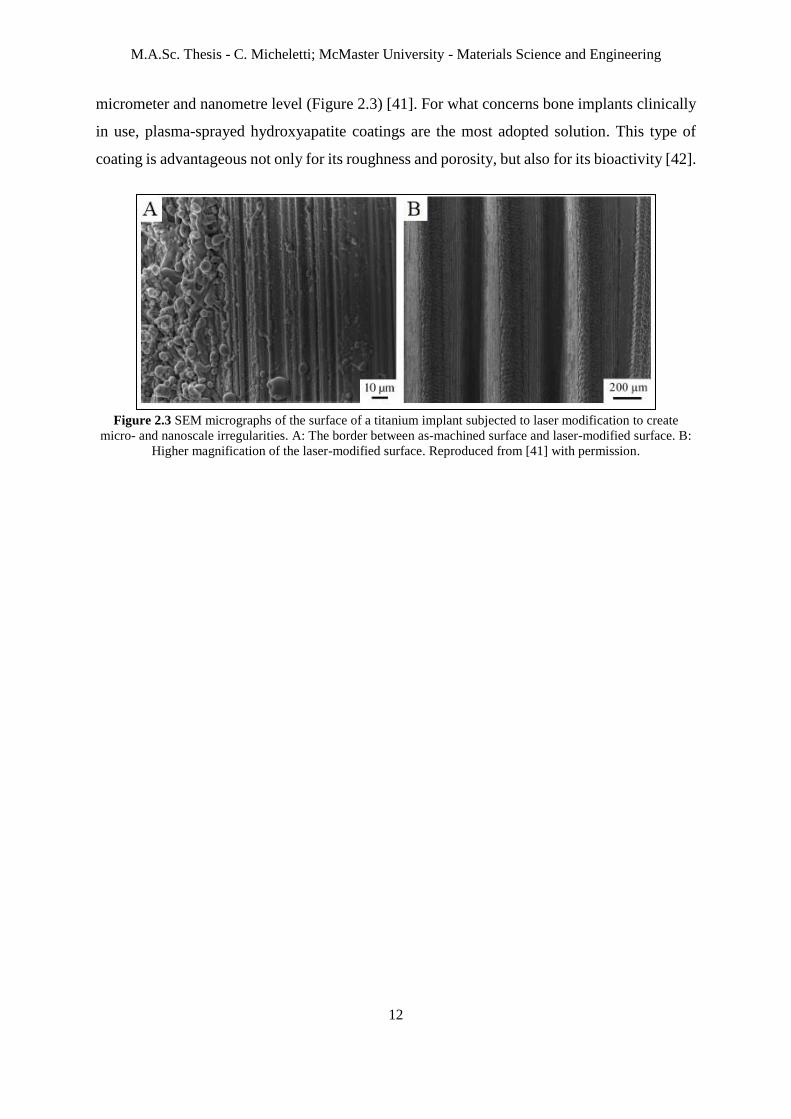
micrometer and nanometre level (Figure 2.3) [41]. For what concerns bone implants clinically
in use, plasma-sprayed hydroxyapatite coatings are the most adopted solution. This type of
coating is advantageous not only for its roughness and porosity, but also for its bioactivity [42].
Figure 2.3 SEM micrographs of the surface of a titanium implant subjected to laser modification to create
micro- and nanoscale irregularities. A: The border between as-machined surface and laser-modified surface. B:
Higher magnification of the laser-modified surface. Reproduced from [41] with permission.

M.A.Sc. Thesis - C. Micheletti; McMaster University - Materials Science and Engineering
13
2.4 Electrochemical anodization and TiO2 nanotubes
A layer of titanium dioxide nanotubes with a controlled and uniform diameter can be produced
by electrochemical anodic oxidation, which is a simple, versatile and cost-effective surface
treatment for metallic implants. Metals like titanium, aluminum, niobium, zirconium and
tantalum, also known as “valve metals”, spontaneously form an ordered nanoporous oxide
layer when used as the anode of an electrochemical cell, if parameters like voltage, current and
electrolyte properties are properly selected [18]. The presence of TNTs on Ti-based implant
surface can improve their biocompatibility, enhance osseointegration thanks to the creation of
a nanoscale topography, and reduce the risk of infections if the nanotubes are employed as a
local drug delivery system [43].
2.4.1 Anodization process
The anodization process is performed in an electrochemical cell either with a two- or three-
electrode configuration [18]. In a two-electrode set-up (Figure 2.4A), the metallic substrate of
interest is employed as the working electrode (anode) and it is immersed in an electrolyte with
a counter-electrode (cathode). The process starts when an external voltage is applied between
anode and cathode, and it usually carried out maintaining the voltage constant [44]. Depending
on the anodization parameters and the electrolyte used, three main reactions can occur in the
electrochemical cell: dissolution of the metal and formation of metal ions that dissolve in the
solution, interaction of metal ions with oxygen ions in the electrolyte to form metal oxide,
which can be deposited as a bulk coating on the anode, or formation of a porous metal oxide
layer if specific conditions lead to a competition between oxide formation and dissolution. In
regard to this last case, such conditions can be obtained using a fluoride-based electrolyte. In
case of titanium anodes, this makes it possible to fabricate well-aligned nanotubular structures,
i.e. TNTs [44].
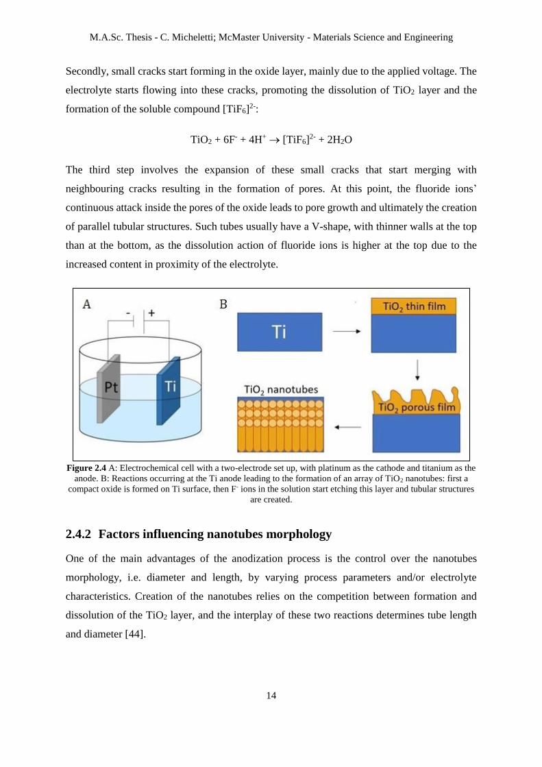
The mechanism of nanotubes formation can be summarized in four steps, schematically
illustrated in Figure 2.4B [44]. First of all, a thin compact layer of TiO2 is formed on the anode
surface, according to the reaction:
Ti + 2H2O → TiO2 + 4H+ + 4e-
M.A.Sc. Thesis - C. Micheletti; McMaster University - Materials Science and Engineering
14
Secondly, small cracks start forming in the oxide layer, mainly due to the applied voltage. The
electrolyte starts flowing into these cracks, promoting the dissolution of TiO2 layer and the
formation of the soluble compound [TiF6]2-:
TiO2 + 6F- + 4H+ → [TiF6]2- + 2H2O
The third step involves the expansion of these small cracks that start merging with
neighbouring cracks resulting in the formation of pores. At this point, the fluoride ions’
continuous attack inside the pores of the oxide leads to pore growth and ultimately the creation
of parallel tubular structures. Such tubes usually have a V-shape, with thinner walls at the top
than at the bottom, as the dissolution action of fluoride ions is higher at the top due to the
increased content in proximity of the electrolyte.
Figure 2.4 A: Electrochemical cell with a two-electrode set up, with platinum as the cathode and titanium as the
anode. B: Reactions occurring at the Ti anode leading to the formation of an array of TiO2 nanotubes: first a
compact oxide is formed on Ti surface, then F- ions in the solution start etching this layer and tubular structures
are created.
2.4.2 Factors influencing nanotubes morphology
One of the main advantages of the anodization process is the control over the nanotubes
morphology, i.e. diameter and length, by varying process parameters and/or electrolyte
characteristics. Creation of the nanotubes relies on the competition between formation and
dissolution of the TiO2 layer, and the interplay of these two reactions determines tube length
and diameter [44].

M.A.Sc. Thesis - C. Micheletti; McMaster University - Materials Science and Engineering
15
2.4.2.1 Electrolyte
Different types of substances can be employed as electrolytes for anodizing titanium, such as
acids, alkaline or natural salts solutions. TiO2 nanotubes are created when using fluoride-based
electrolytes, but some recent developments in the process have lead to the synthesis of
nanotubes even in fluoride-free solutions [45]. Some electrolytes commonly employed consist
of polar organic solvents, such as ethylene glycol, used together with a fluoride-containing
species, for example ammonium fluoride. In general, chemical dissolution and F- ions
transmission is relatively low in organic electrolytes, so nanotubes formed in these conditions
are usually more homogeneous but may be partially covered with a hazy layer [46]. Ethylene
glycol-based solutions have been used to synthesize TNTs at anodization voltages ranging from
20 to 65 V, together with a content of ammonium fluoride usually ranging 0.1 to 0.5 wt.% and
1 to 4 vol.% of water [45]. An example of nanotubes obtained using this type of electrolyte is
shown in Figure 2.5.
Figure 2.5 SEM images of (a) top side, (b) bottom side, (c) cross-section of a TNTs array obtained in an
electrolyte comprised of 0.3 wt.% NH4F and 2 vol.% H2O in ethylene glycol at 60 V. Reproduced from [47]
with permission.
2.4.2.2 Applied voltage
The applied voltage mainly controls the nanotubes diameter. Specifically, the diameter
increases by increasing the voltage. In fact, by increasing the voltage, the movement of ions
increases, thus enhancing the transmission of the ions over the oxide layer, accelerating the
electrochemical etching speed [44].
2.4.2.3 Anodization time
The length of the nanotubes array increases by increasing the anodizing time, as the thickness
of the oxide layer grows with time. However, at a certain point a balance between oxidation
and dissolution of TiO2 is reached, thus the tube length becomes independent on the synthesis
time. In general, more regular nanotubes are formed with a shorter anodization time, while for

M.A.Sc. Thesis - C. Micheletti; McMaster University - Materials Science and Engineering
16
long processes the structure starts to be more irregular, mainly because of the excessive
dissolution along the entire tube length [44].
2.4.3 TiO2 nanotubes and surface modification of bone implants
Electrochemical anodization of titanium has recently grown in interest as a surface
modification technique for Ti-based bone implants to promote osteogenesis, osteoconduction
and osseointegration [48]. Advantages of TNTs coatings on bone implants include their
excellent chemical inertness and therefore biocompatibility, high surface area, mechanical
robustness, and surface chemistry [49], in particular wettability [50].
Studies in literature have shown that anodic TNTs can enhance cell adhesion and function,
accelerate the growth kinetics of hydroxyapatite, and influence bone formation and
development [51]. Despite the fact that the majority of these results have been obtained in in
vitro studies, similar conclusions have been reached in a few in vivo investigations [48].
An interesting aspect is the effect of the nanotube size on cell responses. As cells are sensitive
to topographical cues, electrochemical anodization appears to be a facile approach to obtain
surfaces with specific surface features by controlling the nanotubes diameter. This process, in
fact, can be used to synthesize nanotubes with diameters ranging to virtually any value between
10 and 250 nm [52]. Moreover, the self-ordering nature of the TNTs array makes it possible to
obtain this type of coating even on complex shaped surfaces, such as screws, plates, nails and
wires [49]. Several studies have shown that the tube diameter influences cell adhesion,
proliferation, and differentiation. Different authors have also found that nanotubes with a
diameter around 15 nm show particularly encouraging results for what concerns enhancement
of cell responses [52]. Therefore, anodization of titanium to create TNTs seems to be a
promising strategy of surface modification of bone implants to create a nanoscale topography,
which is believed to be beneficial for osseointegration (Section 2.3).
Moreover, Gulati et al. [28] and Maher et al. [29] have investigated the possibility of producing
TNTs on 3D-printed microrough samples. In this way it would be possible to obtain surfaces
with a dual-scale topography, combining the microscale from the 3D-printed substrates with
the nanoscale of the anodic nanotubes. This dual topography may be beneficial for combining
the advantages of both micro- and nanotopography in order to improve osseointegration.

M.A.Sc. Thesis - C. Micheletti; McMaster University - Materials Science and Engineering
17
3. Materials and Methods
3.1 Samples manufacturing
3D-printed samples of two different titanium alloys, i.e. Ti-6Al-4V (abbr. Ti64) and Ti-5Al-
5Mo-5V-3Cr (abbr. Ti5553) were manufactured by selective laser melting using a direct metal
laser sintering system (EOSINT M 280 by EOS). Powders employed (purchased from AP&C)
had a particle size of 15-45 µm and 25-63 µm for Ti64 and Ti5553, respectively. Layer
thickness used for printing was equal to 60 µm. The samples were manufactured according to
the geometry illustrated in Figure 3.1. This geometry was designed so that the square portion
(10 mm x 10 mm), constituting the area of interest, could be handled using the rectangular part
(10 mm x 3 mm). After manipulation, the rectangular portion of the specimen was easily
removed. This sample design resulted to be convenient for the anodization process further
explained in Section 3.2. To remove manufacturing debris, the samples were sonicated in
ethanol, acetone and deionized water for 15, 15 and 5 minutes, respectively.
Figure 3.1 2D drawing of the geometry of the samples manufactured by SLM. The area of interest (square) is
coloured in blue, the holder (rectangle) in yellow. The sample were 3D-printed with a thickness (not visible in
the 2D view) equal to 1 mm.

M.A.Sc. Thesis - C. Micheletti; McMaster University - Materials Science and Engineering
18
3.2 Anodization
Electrochemical anodization was employed to generate TNTs on 3D-printed Ti64 and Ti5553
samples. A two-electrode set-up was used, with a platinum foil (25 mm x 25 mm x 0.125-
0.135 mm, Sigma Aldrich) as the counter-electrode. The platinum foil (cathode) and the 3D-
printed sample (anode) were connected to a power supply using alligator clips. The clips were
placed onto the rectangular portion of the 3D-printed samples (Figure 3.1). Anode and cathode
were then immersed into the electrolyte solution, such that only the square part of the 3D-
printed sample was immersed in the solution to avoid contamination from the alligator clips
and alteration of expected electrochemical reactions.
A solution of ethylene glycol (certified grade, Fisher Chemical) with 0.3 wt.% of ammonium
fluoride (certified ACS grade, Fisher Chemical) and 2 vol.% of deionized water was used as
electrolyte. The solution was magnetically stirred for 20 minutes before usage to ensure that it
was homogeneous.
Anodization was carried out using different time and voltage conditions. To evaluate the effect
of the voltage on the nanotubes morphology, samples were anodized at a constant voltage of
20 V, 40 V, 60 V and 80 V for 30 minutes. The influence of time was assessed by applying a
constant voltage of 40 V and anodizing for 5, 10, 20 and 60 minutes. Finally, some samples
were anodized by initially increasing the voltage in a stepwise way, as illustrated in Figure 3.2.
Starting from 6 V (due to limitations of the power supply used), the voltage was then
augmented by 1 V every 10 seconds until reaching 40 V; such voltage was then maintained
constant for 30 minutes to complete the anodization process.
In all cases, the electrolyte was slightly magnetically stirred during the whole process. Fresh
solution was used every time. After anodization, the samples were rinsed with ethanol and
deionized water and sonicated in ethanol for 30 seconds.

M.A.Sc. Thesis - C. Micheletti; McMaster University - Materials Science and Engineering
19
Figure 3.2 Trend of the applied anodization voltage as a function of time, and inset section to better illustrate
the initial stepwise increase.
3.2.1 Annealing
As-anodized TNTs are usually made of amorphous titanium dioxide. However, it is possible to
perform a subsequent annealing treatment to make TiO2 crystallize, usually obtaining rutile
and/or anatase, depending on the conditions adopted. Ti64 and Ti5553 samples anodized at
40 V for 30 minutes were annealed in open air at 500 °C for two hours.

M.A.Sc. Thesis - C. Micheletti; McMaster University - Materials Science and Engineering
20
3.3 Characterization
3.3.1 Surface characterization
3.3.1.1 Morphology and topography
Scanning electron microscopy (SEM) is the gold standard for morphological and topographical
characterization at the micrometre and nanometre level [53]. Samples as printed, anodized and
annealed were imaged by SEM using two different instruments, JEOL JSM-7000F and FEI
Magellan 400. Before imaging, samples were mounted on a stub with carbon tape and grounded
using nickel paint to reduce charging effects. Secondary electron images were acquired with
acceleration voltages of 2-3 kV.
The diameter of TNTs obtained using different anodization conditions was measured using
ImageJ. A threshold was first applied to each SEM micrograph to generate a “binary”, black
and white, image, in which nanotubes appeared as ellipses, as shown in the example in Figure
3.3. In this way it was possible to process each image using the “Analyze Particles” command,
which allowed to measure the major and minor axes of each TNT ellipsoid. Finally, the
nanotube diameter was computed as the average of the dimension of major and minor axes.
For each SEM image, the diameter of tens to hundreds of TNTs was measured, and the mean
of all the values was used to represent the nanotube diameter of an entire image. For each
anodization condition, two SEM micrographs were analyzed, i.e. one for a flatter region of the
sample surface and the other for the top of a microspherical particle. The representative
diameters of both images were then averaged to obtain the TNTs diameter corresponding to
each anodization condition under investigation. Finally, Student’s t-test was used to verify if
eventual differences between different groups of samples were statistically significant
(significance level of α = 0.05).

M.A.Sc. Thesis - C. Micheletti; McMaster University - Materials Science and Engineering
21
Figure 3.3 Example of an SEM micrograph as-acquired (left) and after a threshold was applied using ImageJ to
obtain a binary image and identify the TNTs as ellipsoids (right).
3.3.1.2 Roughness
Roughness of the 3D-printed samples was measured by focus variation (Alicona Infinite
Focus), which is a non-contact optical technique for roughness evaluation [54]. Two-
dimensional and three-dimensional reconstructed views of the surface were acquired. Both
profile and surface roughness parameters were measured. Measurements were done in
triplicates and statistically averaged.
3.3.1.3 Wettability
Wettability was evaluated using a contact angle measuring device (DataPhysics Optical
Contact Angle, OCA 35). Values of the contact angle were assessed for the samples as printed
and for the samples anodized at constant voltage for 30 minutes. In both cases, measurements
were done in triplicates and then statistically averaged.
3.3.1.4 Phase analysis
X-ray diffraction (XRD) was used to identify the crystalline phases of the TiO2 nanotubes array
after annealing, in order to assess whether the treatment succeeded in the creation of anatase
and/or rutile. Measurements were obtained by an x-ray diffractometer with Co Kα radiation
(Bruker Discover D8).
3.3.2 Biological characterization
3.3.2.1 Cell imaging
Sarcoma osteogenic (Saos-2) bone-like cells were cultured on Ti64 and Ti5553 samples both
as-printed and anodized at 40 V for 30 minutes. After 1 day, cells grown on the samples were
fixed by glutaraldehyde and stained with osmium tetroxide. Successively, the samples were
M.A.Sc. Thesis - C. Micheletti; McMaster University - Materials Science and Engineering
22
dehydrated using increasingly concentrated solutions of ethanol and dried by critical point
drying. Finally, they were coated with platinum (10 nm) before SEM imaging.
3.3.2.2 Bioactivity
Bioactivity was tested for both Ti64 and Ti5553 using three different groups of samples, i.e.
as-printed, anodized at 40 V for 30 minutes, and annealed after anodization. Samples were
immersed for 3 and 7 days in 25 ml of simulated body fluid (SBF) Hanks’ solution (Hanks’
balanced salts solution without sodium bicarbonate, Sigma-Aldrich) and stored at 37 °C.
Following immersion, the samples were removed from the solution, rinsed with deionized
water and let dry in air. SEM and EDS were used to verify the eventual presence of precipitates,
in particular hydroxyapatite (HA) crystals, on the surface.

M.A.Sc. Thesis - C. Micheletti; McMaster University - Materials Science and Engineering
23
4. Results
4.1 3D-printed samples: microscale topography
4.1.1 Morphology and topography
SLM was used to manufacture Ti64 and Ti5553 samples, representative of possible bone
implant substrates. This technique was selected to produce samples with a microscale surface
topography. Such objective was reached for both the alloys employed, as assessed by SEM
imaging of the as-printed samples. In fact, as shown in Figure 4.1, SEM revealed the presence
of microspherical particles randomly distributed on the surface, which was the expected
outcome of SLM. As shown in the chart in Figure 4.2, the microparticles visible on the surface
were different in size, with diameters approximately ranging from 5 μm to 50 μm, and a mean
diameter around 27 μm.
Figure 4.1 SEM micrographs of as-printed Ti64 (left) and Ti5553 (right) samples. In both cases, the surface is
randomly covered with microspherical particles, which are characteristic of the SLM manufacturing process.

M.A.Sc. Thesis - C. Micheletti; McMaster University - Materials Science and Engineering
24
Figure 4.2 Left: SEM micrograph of an as-printed Ti64 sample showing the size of some microparticles on the
surface. Right: Chart of the size distribution of the microspherical particles in both Ti64 and Ti5553. Data were
obtained analyzing a 350 μm x 350 μm area from a SEM micrograph per alloy and measuring 30 particles in
total.
4.1.2 Roughness
Values of roughness parameters measured by focus variation are reported in Table 4.1. Figure
4.3 and Figure 4.4 show 2D and 3D reconstructed views of the substrates for Ti64 and Ti5553,
respectively. Both as-printed Ti64 and Ti5553 samples proved to have microrough surfaces, as
the roughness parameters measured all laid in the microscale range. The two alloys had
comparable roughness: mean values of arithmetic roughness (Ra), for example, were around
13.0 μm and 15.6 μm for Ti64 and Ti5553, respectively.
Table 4.1 Values of 2D and 3D roughness parameters of as-printed Ti64 and Ti5553 samples.
Ti64 Ti5553
2D roughness
parameters
Ra [μm] 13.0 ± 3.0 15.6 ± 1.7
Rq [μm] 15.6 ± 3.6 19.1 ± 2.2
Rz [μm] 48.4 ± 10.1 56.6 ± 4.6
3D roughness
parameters
Sa [μm] 14.3 ± 1.2 16.9 ± 0.3
Sq [μm] 17.5 ± 1.4 21.0 ± 0.1
Sz [μm] 125.1 ± 9.9 152.9 ± 4.5

M.A.Sc. Thesis - C. Micheletti; McMaster University - Materials Science and Engineering
25
Figure 4.3 2D (left) and 3D (right) views of the surface of a Ti64 sample manufactured by SLM.
Figure 4.4 2D (left) and 3D (right) views of the surface of a Ti5553 sample manufactured by SLM.
4.1.3 Wettability
Both as-printed Ti64 and Ti5553 proved to have a similar and slightly hydrophilic behaviour,
as the water contact angles were (78.2 ± 7.2)° and (79.2 ± 3.6)°, respectively. These mean
values of contact angles were obtained by averaging a set of three measurements per alloy,
reported in Table 4.2.
Table 4.2 Contact angle (CA) values measured for as-printed Ti64 and Ti5553 samples.
CA – Ti64 CA – Ti5553
Measurement 1 86.4° 80.5°
Measurement 2 75.3° 75.0°
Measurement 3 73.0° 81.8°
Mean 78.2° 79.1°
Standard deviation 7.2° 3.6°

M.A.Sc. Thesis - C. Micheletti; McMaster University - Materials Science and Engineering
26
4.1.4 Cell imaging
SEM imaging of the samples seeded with Saos-2 cells revealed the presence of a significant
number of alive (previous sample preparation) cells on the surface of both materials. Not only
were the cells alive, but they also showed an optimal morphology, i.e. flat and stretched, so to
better interact with and have higher adhesion on the substrate. As can be noticed in Figure 4.5
for Ti64 and Figure 4.6 for Ti5553, bone-like cells were found to adhere not only in the flatter
regions of the 3D-printed samples, but they also seemed to interact with the microspherical
features on the surface. In fact, it was repeatedly observed the presence of elongated cells
extending from a flatter area to a microparticle nearby, with their filopodia (i.e. finger-like
cellular protrusions) anchored on it (Figure 4.5C and Figure 4.6C).
Figure 4.5 SEM micrographs showing bone-like cells adhering on a 3D-printed Ti64 sample. Cells are present
both in the flatter areas and stretching from the flatter regions to the microspherical particles. In particular,
micrograph C shows a significantly elongated cell anchoring its filopodia onto a microsphere.
Figure 4.6 SEM micrographs showing bone-like cells adhering on a 3D-printed Ti5553 sample. As in case of
Ti64 (Figure 4.5), cells are anchored both to the flatter areas and to the microspherical particles. In particular, a
cell adhering on a microparticle is visible in micrograph C.

M.A.Sc. Thesis - C. Micheletti; McMaster University - Materials Science and Engineering
27
4.1.5 Bioactivity
Samples of Ti64 and Ti5553 immersed in Hanks’ solution for 3 days showed little bioactivity,
as very few precipitates were distinguishable on the surface. On the other hand, more
precipitates were present after 7-day immersion (Figure 4.7). EDS analysis revealed the
presence of elements like P, Ca, Cl and K, which are characteristic of the solution used.
Notably, the presence of Ca and P suggested that some precipitates on the surface may have
been crystals of hydroxyapatite, and not simply generic salts precipitated from the solution.
Figure 4.7 SEM image showing some precipitates on the surface of a Ti5553 sample immersed in Hanks’
solution for 7 days, and its correspondent EDS analysis. Peaks relative to Ca, K, Cl and P are distinguishable in
the EDS spectrum.

M.A.Sc. Thesis - C. Micheletti; McMaster University - Materials Science and Engineering
28
4.2 Anodized samples: dual-scale topography
4.2.1 Morphology and topography
In general, anodization of 3D-printed Ti64 and Ti5553 succeeded in the formation of TiO2
nanotubes. The presence of these nanoscale features together with the microparticles
characteristic of the as-printed samples contributed to the creation of a dual-scale surface
topography, which was the main goal of this research work.
4.2.1.1 Anodization at constant voltage
Both Ti64 and Ti5553 were anodized at 20 V, 40 V, 60 V and 80 V for 30 minutes following
the process described in Section 3.2. In all cases, anodization resulted in the obtainment of
arrays of titanium dioxide nanotubes over the entire surface, both on the microparticles and on
the underlying substrate. An example of the morphology generated by anodization is given in
Figure 4.8.
Figure 4.8 Top (left) and bottom (right) views of TNTs. Left and right images correspond to a Ti64 sample
anodized for 30 minutes at 60 V and 40 V, respectively.
The process also resulted in the formation of cracks across the surface, especially in the less
flat areas and on the microparticles (Figure 4.9). Cracks are due to the outgrowth mechanism
of the nanotubes, perpendicularly with respect to the substrate and following its morphology.
Therefore, along the curved surfaces they tend to separate into arrays tangent to the regions
underneath. Cracks appeared to be more extended for higher anodization voltages, which may
be due to the increase in the electrochemical etching. The presence of cracks enabled to have a
side-view of the TNTs arrays, as shown in Figure 4.10. This was important to confirm that

M.A.Sc. Thesis - C. Micheletti; McMaster University - Materials Science and Engineering
29
anodization did not just form nanopores on the surface, but tubular structures, i.e. TiO2
nanotubes.
Figure 4.9 Left: Cracks visible on the surface on an anodized Ti64 sample (anodization at 60 V for 30 minutes),
in particular across the microspherical particles. Right: Higher magnification image showing TNTs arrays
separated by cracks on a microparticle.
Figure 4.10 Left: Microspherical particle on an anodized Ti64 sample (anodization at 40 V for 30 minutes) with
a missing TNTs array, whose detachment may have been promoted by the presence of cracks. Right: Higher
magnification image showing a side-view of the TNTs. The barrier layer, i.e. a layer of amorphous TiO2 that
forms in between the substrate and the TNTs [50], is also visible.
Anodization of Ti64 resulted in the creation of well-organized nanotubes arrays on the surface
when a voltage of 20 V, 40 V or 60 V was applied. A different behaviour was observed for
Ti64 anodized at 80 V. In this case, in several areas there was no evidence of tubular structures
although some nanotubes were still identified on the surface. The reason is that electrochemical
etching increases at higher voltages, and this in turn makes the tube wall thinner, especially at
the top where etching is more intense. Therefore, TNTs generated at 80 V started to disintegrate
and collapse onto the neighbouring tubes, merging into each other and leading to the formation
of a disordered TiO2 structure, shown in Figure 4.11. This structure is usually referred to as
“nanograss”, and it constitutes a quite common and undesired outcome of anodization

M.A.Sc. Thesis - C. Micheletti; McMaster University - Materials Science and Engineering
30
processes [55]. Nanograss was often noticed also on samples anodized at lower voltages (20,
40 and 60 V), but less extended than that formed at 80 V.
Figure 4.11 SEM image of a Ti64 sample anodized at 80 V for 30 minutes, in which it is visible how several
TNTs collapsed and merged into each other forming nanograss.
Arrays of TiO2 nanotubes were obtained on the surface of Ti5553 for all the four different
anodization voltages investigated. In contrast to what observed for Ti64, nanotubes were
consistently created also at a voltage equal to 80 V, even though significantly extended
formations of nanograss were identified in some areas of the surface. In general, nanotube
architecture seemed to be less stable in the case of Ti5553 than Ti64, as the TNTs often
appeared less intact and cracked at the top, leading sometimes to the formation of vast regions
of nanograss. Moreover, some inconsistencies in the TNTs morphology were noticed for
Ti5553 samples, such as nanotubes that seemed to have a double wall (Figure 4.12).
Differences in the behaviour of Ti64 and Ti5553 when anodized can be attributed to the
different quantity and type of alloying elements. In fact, different elements can show different
electrochemical oxidation rates, thus different reaction rates leading to selective dissolution
[18]. This may also constitute the reason why some anomalies were detected for anodized
Ti5553 samples.

M.A.Sc. Thesis - C. Micheletti; McMaster University - Materials Science and Engineering
31
Figure 4.12 Example of anomalous TNTs obtained by anodizing Ti5553 at 60 V for 30 minutes. Nanotubes
seems to have a double wall, and extended regions of nanograss are present.
4.2.1.2 Influence of voltage on TNTs diameter
To evaluate the influence of the anodization voltage on the nanotubes diameter, Ti64 and
Ti5553 were anodized for the same length of time (30 minutes) using four different voltages,
namely 20 V, 40 V, 60 V and 80 V. SEM images representative of the TNTs obtained at each
condition are shown in Figure 4.13 for Ti64 and in Figure 4.14 for Ti5553. For every case,
TNTs diameter was measured following the methodology illustrated in Section 3.3.1.1. For
what concerns Ti64 anodized at 80 V, it was possible to analyze a SEM image corresponding
to a microparticle only, as TNTs with a morphology suitable for detailed measurements were
not identified in the flatter regions of the sample. In regard to Ti5553, areas showing the
anomalies mentioned before (Section 4.2.1.1) were excluded from the analysis, and only
regions with TNTs with a consistent morphology were taken into account. The results obtained
for both the alloys at each anodization voltage are reported in Table 4.3.

M.A.Sc. Thesis - C. Micheletti; McMaster University - Materials Science and Engineering
32
Figure 4.13 SEM images of TNTs generated by anodization of Ti64 for 30 minutes at 20 V (A), 40 V (B), 60 V
(C) and 80 V (D).
Figure 4.14 SEM images of TNTs generated by anodization of Ti5553 for 30 minutes at 20 V (A), 40 V (B),
60 V (C) and 80 V (D).

M.A.Sc. Thesis - C. Micheletti; McMaster University - Materials Science and Engineering
33
Table 4.3 Mean diameter of TNTs generated by anodization of Ti64 and Ti5553 for 30 minutes at four different
voltages.
Voltage [V] TNTs diameter for Ti64 [nm] TNTs diameter for Ti5553 [nm]
20 22.1 ± 5.6 26.5 ± 6.4
40 47.3 ± 8.9 52.2 ± 9.8
60 67.5 ± 10.6 87.2 ± 8.8
80 59.1 ± 5.2 97.0 ± 15.4
With the exception of Ti64 anodized at 80 V, it was observed that the nanotube diameter
increased with the applied voltage. For both the alloys, the differences in the values obtained
at each voltage were statistically significant, as verified by Student’s t-test. As can be observed
from the values in Table 4.3, TNTs of Ti64 anodized at 80 V showed a diameter lower than
those of Ti64 anodized at 60 V, in contrast to what was expected. It is believed that Ti64
anodized at 80 V differ from the common trend due to extensive electrochemical etching which
caused the collapsing of the nanotubes into nanograss. TNTs with larger diameters might have
proved to be more unstable, thus etching may have been more substantial for them leading to
their disintegration. This in turn could explain why only smaller TNTs preserved their tubular
architecture, and thus only areas with smaller nanotubes were identifiable to be used for further
analysis.
The TNTs diameter was observed not only to increase with the applied voltage, but to do so
following a linear trend. This was valid for both the alloys at every condition tested, excluding
the case of Ti64 anodized at 80 V, as already discussed. The graph in Figure 4.15 reports the
variation of the TNTs diameter (data used were those reported in Table 4.3) as a function of
the applied voltage. The data points fit a linear regression model well, enabling to identify a
trendline with a high coefficient of determination (R2 tending towards 1). The slope of the
trendline was computed to be equal to 1.14 and 1.30 for Ti64 and Ti5553, respectively. Ti64
anodized at 80 V was omitted from this analysis, as it did not follow the expected linear trend.
Finally, it was observed that TNTs on Ti5553 showed a larger diameter than those on Ti64 at
every anodization voltage, and Student’s t-test proved the difference to be statistically
significant in all cases.

M.A.Sc. Thesis - C. Micheletti; McMaster University - Materials Science and Engineering
34
Figure 4.15 Graphs showing the variation in TNTs diameter as a function of the anodization voltage for both
Ti64 and Ti5553.
4.2.1.3 Influence of time on TNTs morphology
Ti64 and Ti5553 were anodized at a constant voltage of 40 V for four different lengths of time,
i.e. 5, 10, 20 and 60 minutes, to evaluate the influence of time on TNTs formation and
morphology.
Figure 4.16 and Figure 4.17 show how the nanotubes morphology evolved over time for Ti64
and Ti5553, respectively. In both cases it was noticed that after 5 minutes the surface was
mainly characterized by the presence of nanopores rather than nanotubes. Some tubular
structures were identified, but there was no evidence of significantly extended arrays of TNTs.
Samples anodized for 10 minutes showed a similar behaviour, but pores were higher in number
and seemed to start assuming an ordered pattern. After 20 minutes, well-organized arrays of
TNTs were present on the entire surface of both Ti64 and Ti5553, with a morphology close to

M.A.Sc. Thesis - C. Micheletti; McMaster University - Materials Science and Engineering
35
that observed for an anodization time of 30 minutes, explained in more detail before (Section
4.2.1.1). TNTs were still noticeable after 60-minute long anodization, but in some areas
extended nanograss structures were observed, in agreement with the fact that nanograss is
usually more widespread for longer anodization time.
Figure 4.16 Morphology of TNTs on Ti64 anodized at 40 V for 5 (A), 10 (B), 20 (C) and 60 (D) minutes.

M.A.Sc. Thesis - C. Micheletti; McMaster University - Materials Science and Engineering
36
Figure 4.17 Morphology of TNTs on Ti5553 anodized at 40 V for 5 (A), 10 (B), 20 (C) and 60 (D) minutes.
4.2.1.4 Anodization with initial stepwise increase of voltage
Ti64 and Ti5553 were anodized with an initial stepwise increase of voltage of 1 V every 10
seconds, until a voltage of 40 V was reached and then maintained constant for 30 minutes
(Figure 3.2). The objective was to assess eventual differences in the outcome of the process
and in the TNTs morphology if compared to Ti64 and Ti5553 anodized at a constant voltage
of 40 V (instantly applied at the start and kept constant for the entire process). For the sake of
simplicity, anodization at constant voltage will be indicated as case I, while anodization with
initial stepwise increase of voltage will be referred to as case II.
Well-ordered arrays of TNTs were successfully created both for Ti64 and Ti5553 under case
II process conditions (Figure 4.18). Moreover, the nanotubes were found to be distributed over
the entire surface of the samples, as obtained for case I as well (Section 4.2.1.1). Case II TNTs
morphology did not appear to be different to that of case I. Features such as nanograss and
cracks, commented in Section 4.2.1.1 for case I, were identified in case II as well. The lack of
visible differences between case I and case II led to the conclusion that the initial stepwise
increase of voltage did not affect the outcome of the process in terms of surface characteristics
and TNTs morphology. This result may be strictly linked to the specific stepwise increase used,
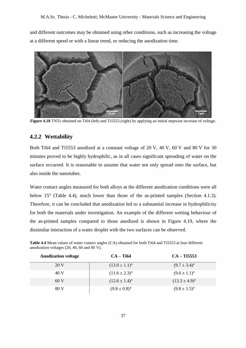
M.A.Sc. Thesis - C. Micheletti; McMaster University - Materials Science and Engineering
37
and different outcomes may be obtained using other conditions, such as increasing the voltage
at a different speed or with a linear trend, or reducing the anodization time.
Figure 4.18 TNTs obtained on Ti64 (left) and Ti5553 (right) by applying an initial stepwise increase of voltage.
4.2.2 Wettability
Both Ti64 and Ti5553 anodized at a constant voltage of 20 V, 40 V, 60 V and 80 V for 30
minutes proved to be highly hydrophilic, as in all cases significant spreading of water on the
surface occurred. It is reasonable to assume that water not only spread onto the surface, but
also inside the nanotubes.
Water contact angles measured for both alloys at the different anodization conditions were all
below 15° (Table 4.4), much lower than those of the as-printed samples (Section 4.1.3).
Therefore, it can be concluded that anodization led to a substantial increase in hydrophilicity
for both the materials under investigation. An example of the different wetting behaviour of
the as-printed samples compared to those anodized is shown in Figure 4.19, where the
dissimilar interaction of a water droplet with the two surfaces can be observed.
Table 4.4 Mean values of water contact angles (CA) obtained for both Ti64 and Ti5553 at four different
anodization voltages (20, 40, 60 and 80 V).
Anodization voltage CA – Ti64 CA – Ti5553
20 V (13.0 ± 1.1)° (9.7 ± 3.4)°
40 V (11.6 ± 2.3)° (9.6 ± 1.1)°
60 V (12.6 ± 1.4)° (13.3 ± 4.9)°
80 V (9.8 ± 0.8)° (9.8 ± 1.5)°
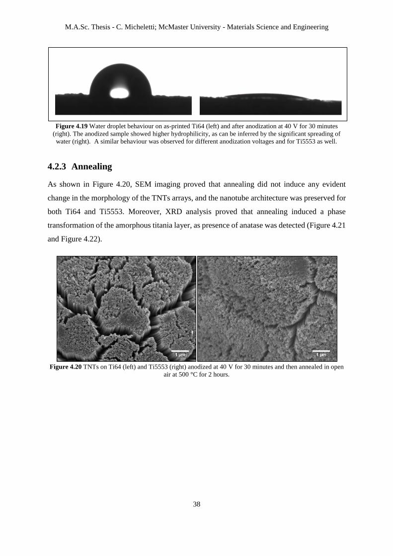
M.A.Sc. Thesis - C. Micheletti; McMaster University - Materials Science and Engineering
38
Figure 4.19 Water droplet behaviour on as-printed Ti64 (left) and after anodization at 40 V for 30 minutes
(right). The anodized sample showed higher hydrophilicity, as can be inferred by the significant spreading of
water (right). A similar behaviour was observed for different anodization voltages and for Ti5553 as well.
4.2.3 Annealing
As shown in Figure 4.20, SEM imaging proved that annealing did not induce any evident
change in the morphology of the TNTs arrays, and the nanotube architecture was preserved for
both Ti64 and Ti5553. Moreover, XRD analysis proved that annealing induced a phase
transformation of the amorphous titania layer, as presence of anatase was detected (Figure 4.21
and Figure 4.22).
Figure 4.20 TNTs on Ti64 (left) and Ti5553 (right) anodized at 40 V for 30 minutes and then annealed in open
air at 500 °C for 2 hours.

M.A.Sc. Thesis - C. Micheletti; McMaster University - Materials Science and Engineering
39
Figure 4.21 XRD spectrum of an anodized and annealed Ti64 sample. Peaks identified by green lines
correspond to anatase. Red lines indicate titanium, most likely from the substrate underneath the TNTs film.
Figure 4.22 XRD spectrum of an anodized and annealed Ti5553 sample. Peaks identified by green lines
correspond to anatase. Red lines indicate titanium, most likely from the substrate underneath the TNTs film. A
compound of titanium-vanadium-chromium (0.7Ti-0.1V-0.2Cr) was also detected (peaks marked by blue lines).
4.2.4 Cell imaging
Samples of Ti64 and Ti5553 anodized at 40 V for 30 minutes were seeded with Saos-2 cells
and prepared for SEM imaging as described in Section 3.3.2.1. Cells were identified on the
surface of both substrates. Overall, cells were characterized by a flat morphology and seemed
to be well-adhering on the surface and to interact with the TNTs on it, as their filopodia
appeared to grow into the nanotubes (Figure 4.23). Analogously to what observed for the as-
printed samples (Section 4.1.4), cells were present both in the flatter regions and stretching
from these areas to the microspheres nearby (Figure 4.24). In addition, cells seemed to interact
with the microparticles on the surface more than what observed for the as-printed samples. The

M.A.Sc. Thesis - C. Micheletti; McMaster University - Materials Science and Engineering
40
different behaviour can be attributed to the presence of TNTs, which promoted the adhesion of
cells also on the microparticles, that otherwise may not show suitable features to facilitate cell-
surface interactions.
Figure 4.23 SEM micrograph showing cell filopodia interacting with TNTs on the surface of anodized Ti64
(left) and Ti5553 (right) samples.
Figure 4.24 Left: Cell on a flat area of an anodized Ti5553 sample. Right: Cell adhering both on some
microparticles and on a flat region of an anodized Ti64 sample.
4.2.5 Bioactivity
Some precipitates were observed on the surface of both as-anodized and anodized and annealed
samples of Ti64 and Ti5553 after immersion in Hanks’ solution for 3 and 7 days. EDS analysis
identified elements such as P, Ca, Na, Mg and K, which are all contained in the Hanks’ solution
used. In particular, the presence of P and Ca may be indicative of hydroxyapatite. It is hence
believed that precipitation of some salts from the solution and nucleation of hydroxyapatite
crystals occurred although difficult to be clearly detected by SEM imaging. Therefore, it was
hypothesized that salts and HA mostly precipitated inside the nanotubes, filling their cavities
and growing on the top of them. For example, TNTs in Figure 4.25 appeared to be closed on
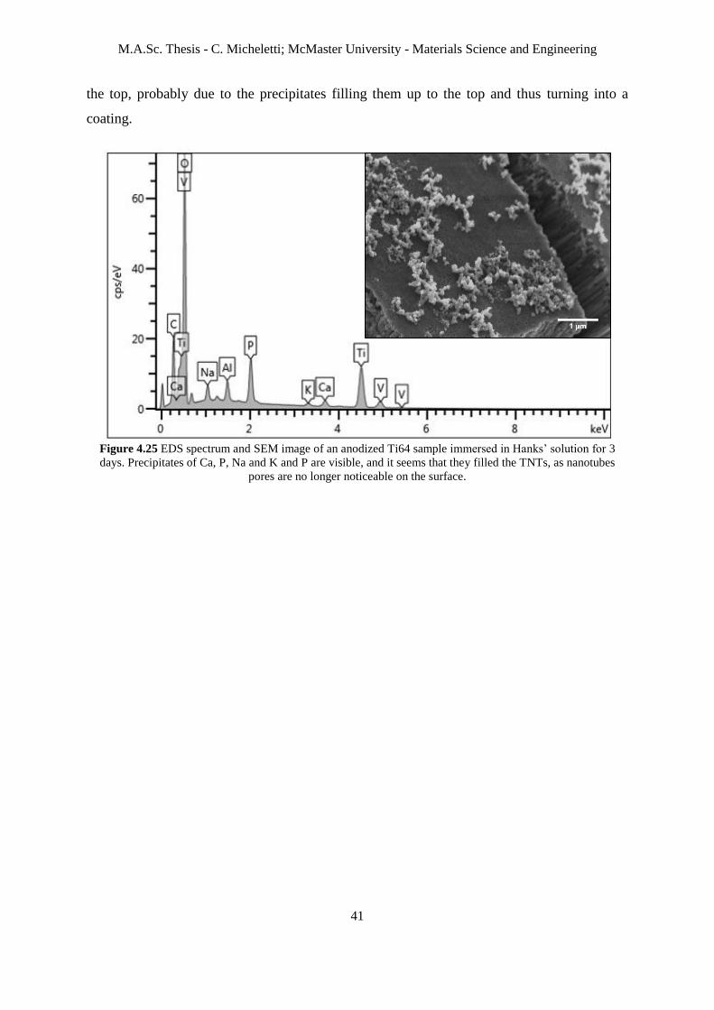
M.A.Sc. Thesis - C. Micheletti; McMaster University - Materials Science and Engineering
41
the top, probably due to the precipitates filling them up to the top and thus turning into a
coating.
Figure 4.25 EDS spectrum and SEM image of an anodized Ti64 sample immersed in Hanks’ solution for 3
days. Precipitates of Ca, P, Na and K and P are visible, and it seems that they filled the TNTs, as nanotubes
pores are no longer noticeable on the surface.

M.A.Sc. Thesis - C. Micheletti; McMaster University - Materials Science and Engineering
42
5. Discussion
Bone implants with a microscale surface topography have been shown to have an improved
ability to osseointegrate [3]. Selective laser melting has emerged as a promising technique to
manufacture implants mainly due to the possibility to manufacture highly customized parts, to
better meet patient-specific needs, and inherently microrough components [24]. Previous work
has already demonstrated the use of SLM for the fabrication of microrough parts of both Ti64
[25] and Ti5553 [56]. A typical feature of substrates manufactured by SLM is their surface
covered by randomly distributed microspherical particles, mainly traces of unmelted feedstock
powders [26]. Ti64 and Ti5553 samples used in this work showed this characteristic
morphology (Figure 4.1), concordantly to what reported in other studies [25], [28]. While the
manufacturing of Ti64 using SLM has already been investigated for biomedical applications
[28], [29], to our knowledge studies on the use Ti5553 in this field have not been reported.
However, being Ti5553 a metastable β alloy, it could be a suitable candidate as a bone implant
material, due to its lower elastic modulus, closer to that of bone [7].
Not only microscale, but also nanoscale surface topography is believed to play a key role in
promoting bone cell functions, and thus osseointegration [31]. To this regard, anodization of
titanium to create TiO2 nanotubes has been intensively investigated [48], [49], [52]. Several
studies reported an improvement in cell adhesion, proliferation and differentiation determined
by the presence of these nanostructured features [50], [57]. Electrochemical anodization is a
promising surface modification technique because, thanks to their self-ordering nature, well-
ordered arrays of TNTs can be obtained even on substrates with complex geometries, which is
fitting for bone implants. Moreover, electrochemical anodization permits high control over the
nanotube size by properly selecting process parameters like electrolyte composition, time and
voltage [44]. As cell-surface interactions are highly influenced by topographical clues, the
possibility to easily produce surface features with highly-specific dimensions makes it possible
to better control such interactions, and, ultimately, osseointegration [31]. Studies have shown
how bone cell responses are influenced by TNTs diameter [58], which is mainly dependent on
the anodization voltage [44]. Therefore, it was considered of importance for this research to
analyze in detail on how the nanotube size was controlled by the applied voltage for both Ti64
and Ti5553 produced by SLM. For both materials, a linear relationship between the two
variables was identified. This is in agreement to what previously observed for flat titanium

M.A.Sc. Thesis - C. Micheletti; McMaster University - Materials Science and Engineering
43
substrates [44], [52], thus neither the use of different Ti-based materials nor the use of samples
with a microscale topography altered the expected trend.
Given the advantages of both micro- and nanoscale on enhancing osseointegration, Maher et
al. [29] and Gulati et al. [28] proposed a new generation of Ti implants that combines these
two scales. They created this unique dual topography by electrochemically anodizing Ti64
samples manufactured by SLM, so that nanoscale of TNTs and microscale characteristic of
SLM can be combined. A similar approach was applied in this work with two Ti alloys, i.e.
Ti64 and Ti5553. Although the present study adopted some different conditions both in the
SLM manufacturing (layer thickness, sample geometry, materials) and in the anodization
stages (electrolyte composition, counter-electrode, process parameters), the results obtained
were analogous to those presented in [28] and [29]. In particular, this work proved the
electrochemical anodization of SLM substrates to be successful not only for Ti64, but also for
Ti5553. To our knowledge, anodization of Ti5553 manufactured by SLM has never been
reported.
In agreement with observations by Gulati et al., anodization of curved surfaces led to the
formation of cracks in the TNTs film, as a consequence of the growth mechanism of nanotubes
and internal stresses [59]. The presence of cracks may compromise the stability of the TNTs
and their adhesion to the substrate. Concerning this, detachment of the anodic coating was
sometimes observed in localized areas of the samples under investigation, as shown in Figure
4.10. Poor bonding of the TNTs film to the surface of a bone implant can be detrimental for
the success of implant itself, therefore anodization of complex geometries, which are typical
of bone implants, without cracks is desirable [59]. In this work, we attempted to reduce crack
formation by using a slow voltage ramping approach, unfortunately with no significant effect
on crack reduction. Coating adhesion was also not possible to measure through standard
procedures such as scratch testing, due to the inherent microroughness of the SLM substrate.
Anodized Ti64 and Ti5553 samples showed higher hydrophilicity compared to as-printed
substrates, as TiO2 nanotubes typically show a hydrophilic behaviour, as proved by others as
well [60]. The increase in hydrophilicity could be beneficial in the context of bone implants,
as hydrophilic surfaces can promote the initial interactions between the surface itself and the
wetting liquid, which is an important aspect for both wound healing and osseointegration [61].

M.A.Sc. Thesis - C. Micheletti; McMaster University - Materials Science and Engineering
44
SEM imaging after Saos-2 culturing showed that the cells well adhered on the surface of both
as-printed and as-anodized Ti64 and Ti5553 samples. In particular, it was observed that cells
greatly interacted with the nanotubes, as their filopodia were noticed to be extended inside the
nanotubes themselves. An analogous behaviour was reported by others as well [62]. Some
studies present in literature further corroborated the hypothesis that TNTs can influence and
improve cell responses with in vitro tests [57]. Moreover, improvement in osteoblast adhesion
was found for substrates with a dual-scale topography [28], [29]. Future work will probe the
time-resolved response of cells to these substrates.
It is believed that further enhancement in cell responses can be achieved by annealing after
anodization. In fact, annealing can promote the phase transformation of the amorphous as-
anodized TiO2 layer into the crystalline forms of rutile and/or anatase, which are considered to
improve cell adhesion [62]. Selection of suitable annealing parameters, especially time and
temperature, is important, as the phase transformation induced by annealing can cause the
collapse and disintegration of the TiO2 nanotubes, with consequent loss of nanotubular
architecture [63]. Annealing conditions used for this research were identified based on previous
studies [62] not to have this undesired outcome, which was, in fact, avoided. XRD analysis on
the annealed Ti64 and Ti5553 samples detected the presence of anatase, in agreement with
other studies [62], [63].
Finally, surface modification to generate TNTs can be beneficial for improving bioactivity,
which can be poor in case of machined Ti-based bone implants. Higher bioactivity is important
to promote the bonding between implant and host tissue, i.e. to increase osseointegration [1].
In vivo bioactivity of a material can be predicted by evaluating its apatite-forming ability, which
can be assessed in a simulated body fluid [64]. Preliminary investigations carried out in this
work identified the presence of precipitates of Ca and P, indicative of apatite, on the surface of
Ti64 and Ti5553, especially when TNTs are present. This seems to confirm the improvement
in bioactivity related to TNTs proved in other studies [65].

M.A.Sc. Thesis - C. Micheletti; McMaster University - Materials Science and Engineering
45
6. Conclusions
6.1 Summary of major findings
The present research reached its main objective of creating TiO2 nanotubes by electrochemical
anodization of Ti64 and Ti5553 samples manufactured by SLM. In particular, to our
knowledge, anodization of 3D-printed Ti5553 samples has not been previously investigated.
For both the alloys used, a dual-scale surface topography was obtained by combining
microscale of 3D-printed substrates and nanoscale of TNTs generated by anodization. Implants
with such dual-scale topography have been proposed as the new generation of multi-functional
bone implants, able to improve osseointegration while addressing at the same time other issues
such as drug delivery [28].
Study on the influence of voltage on the nanotubes diameter proved anodization to be an easy
way to control the size of the nanoscale features generated by adjusting process parameters.
Previous work already outlined the linear dependence of diameter on voltage in case of TNTs
on flat titanium substrates [44], [52], and this research confirmed this trend to be valid also in
case of two different titanium alloys, i.e. Ti64 and Ti5553, and for samples with an initial
microscale surface topography.
Anodization of 3D-printed samples contributed not only to the creation of a dual-scale surface
topography, but also led to a significant increase in surface hydrophilicity, which could be
beneficial for osseointegration and wound healing.
Annealing after anodization did not cause alteration in the nanotubular architecture and
succeeded in the transformation of amorphous TiO2 into anatase, which can improve cell
adhesion [62].
Cell imaging by SEM showed that the substrates, both as-printed and as-anodized, were not
cytotoxic, and showed bone-like cells to be well-adhered on the surface. In particular,
promising interaction between cell filopodia and nanoscale surface features, namely TNTs, was
observed for the anodized samples. The two alloys share similar morphology, while having
different composition, and no apparent difference in cellular response was noted. Further
cellular assays over longer periods of time would be needed to determine if the alloy
composition affects cellular activity.
M.A.Sc. Thesis - C. Micheletti; McMaster University - Materials Science and Engineering
46
Finally, presence of Ca and P precipitates on the surface of the samples immersed in SBF
Hanks’ solution is considered promising for what concerns their bioactive properties.
6.2 Limitations and future directions
Although anodization succeeded in the creation of well-ordered arrays of TNTs, the process
also resulted in generation of cracks on the curved substrates employed. This could constitute
a potential limitation to its employability with bone implants, as they often have complex
geometries. Further tests should be done to assess whether the presence of cracks may
compromise the stability and adhesion of the TNTs film to the substrate underneath.
Cell imaging provided some qualitative preliminary information about the interaction of bone-
like cells and the substrates under investigation. However, more detailed studies on their
biocompatibility would be fitting, as such substrates are representative of possible material
systems for manufacturing bone implants. Therefore, further investigations would involve in
vitro tests to quantitatively assess cellular responses by determining, for example, cell
metabolism, which in turn can provide information on cell viability, and ability to promote new
bone growth. In vitro studies would be also useful to better compare and highlight eventual
dissimilarities in the two alloys employed in this research (Ti64 and Ti5553) and in the three
different groups of samples investigated (as-printed, as-anodized, and anodized and annealed).
In vitro tests could provide indicative information about cell responses to the substrates under
analysis, but they still would not be sufficient to assess osseointegration. In fact, when
collocating this project in the broader scenario of bone implants, its ultimate goal is to
determine whether or not dual-scale topography can improve osseointegration. Therefore, it
would be necessary to do some in vivo studies to really investigate the ability to osseointegrate
of the as-printed, as-anodized, and anodized and annealed samples, for both Ti64 and Ti5553.
Finally, TNTs could be loaded with a therapeutic agent to realize drug-eluting TNTs-Ti
implants. Furthermore, coating of the drug-loaded nanotubes with a biodegradable polymer
could be also investigated to better control the drug release kinetics by adjusting the polymer
degradation rate [66].

M.A.Sc. Thesis - C. Micheletti; McMaster University - Materials Science and Engineering
47
References
[1] D. A. Puleo and A. Nanci, “Understanding and controlling the bone implant-interface,”
Biomaterials, vol. 20, no. 23–24, pp. 2311–21, 1999.
[2] N. R. Van, “Titanium: the implant material of today,” J. Mater. Sci., vol. 22, pp. 3801–
3811, 1987.
[3] S. Bauer, P. Schmuki, K. von der Mark, and J. Park, “Engineering biocompatible implant
surfaces: Part I: Materials and surfaces,” Prog. Mater. Sci., vol. 58, no. 3, pp. 261–326,
2013.
[4] K. Grandfield, “Bone, implants, and their interfaces,” Phys. Today, vol. 68, no. 4, pp.
40–45, 2015.
[5] S. Kurtz, K. Ong, E. Lau, F. Mowat, and M. Halpern, “Projections of primary and
revision hip and knee arthroplasty in the United States from 2005 to 2030,” J. Bone Jt.
Surg. - Ser. A, vol. 89, no. 4, pp. 780–785, 2007.
[6] J. Raphel, M. Holodniy, S. B. Goodman, and S. C. Heilshorn, “Multifunctional coatings
to simultaneously promote osseointegration and prevent infection of orthopaedic
implants,” Biomaterials, vol. 84, pp. 301–314, 2016.
[7] Y. Li, C. Yang, H. Zhao, S. Qu, X. Li, and Y. Li, “New developments of Ti-based alloys
for biomedical applications,” Materials, vol. 7, no. 3, pp. 1709–1800, 2014.
[8] X. Liu, P. K. Chu, and C. Ding, “Surface modification of titanium, titanium alloys, and
related materials for biomedical applications,” Mater. Sci. Eng. R Reports, vol. 47, no.
3–4, pp. 49–121, 2004.
[9] D. M. Dohan Ehrenfest, P. G. Coelho, B. S. Kang, Y. T. Sul, and T. Albrektsson,
“Classification of osseointegrated implant surfaces: Materials, chemistry and
topography,” Trends Biotechnol., vol. 28, no. 4, pp. 198–206, 2010.
[10] Q. Chen and G. A. Thouas, “Metallic implant biomaterials,” Mater. Sci. Eng. R Reports,
vol. 87, pp. 1–57, 2015.
[11] J. Park and R. S. Lakes, Biomaterials: An Introduction. Springer, 2007.
[12] D. F. Williams, “On the mechanisms of biocompatibility,” Biomaterials, vol. 29, no. 20,
pp. 2941–2953, 2008.
[13] M. Geetha, A. K. Singh, R. Asokamani, and A. K. Gogia, “Ti based biomaterials, the
ultimate choice for orthopaedic implants - A review,” Prog. Mater. Sci., vol. 54, no. 3,
pp. 397–425, 2009.
[14] W. Murphy, J. Black, and G. Hastings, Handbook of Biomaterials Properties. Springer,
2016.
[15] S. Parithimarkalaignan and T. V. Padmanabhan, “Osseointegration: An update,” J.
Indian Prosthodont. Soc., vol. 13, no. 1, pp. 2–6, 2013.
[16] M. Niinomi, “Mechanical properties of biomedical titanium alloys,” Mater. Sci. Eng. A,
vol. 243, no. 1–2, pp. 231–236, 1998.
[17] M. A.-H. Gepreel and M. Niinomi, “Biocompatibility of Ti-alloys for long-term
implantation,” J. Mech. Behav. Biomed. Mater., vol. 20, pp. 407–415, 2013.
[18] S. Minagar, C. C. Berndt, J. Wang, E. Ivanova, and C. Wen, “A review of the application
of anodization for the fabrication of nanotubes on metal implant surfaces,” Acta
Biomater., vol. 8, no. 8, pp. 2875–2888, 2012.

M.A.Sc. Thesis - C. Micheletti; McMaster University - Materials Science and Engineering
48
[19] T. Campbell, C. Williams, O. Ivanova, and B. Garrett, “Could 3D printing change the
world?,” 2011.
[20] A. Bandyopadhyay and S. Bose, Additive Manufacturing - Innovations, advances, and
applications, Taylor & F. 2016.
[21] C. L. Ventola, “Medical applications for 3D printing: Current and projected uses,” P&T,
vol. 39, no. 10, pp. 704–711, 2014.
[22] A. Bandyopadhyay, S. Bose, and S. Das, “3D printing of biomaterials,” MRS Bull., vol.
40, no. 2, pp. 108–114, 2015.
[23] W. E. Frazier, “Metal additive manufacturing: A review,” J. Mater. Eng. Perform., vol.
23, no. 6, pp. 1917–1928, 2014.
[24] S. Bose, S. F. Robertson, and A. Bandyopadhyay, “Surface modification of biomaterials
and biomedical devices using additive manufacturing,” Acta Biomater., vol. 66, pp. 6–
22, 2018.
[25] E. Sallica-Leva, A. L. Jardini, and J. B. Fogagnolo, “Microstructure and mechanical
behavior of porous Ti-6Al-4V parts obtained by selective laser melting,” J. Mech.
Behav. Biomed. Mater., vol. 26, pp. 98–108, 2013.
[26] G. Pyka et al., “Surface modification of Ti6Al4V open porous structures produced by
additive manufacturing,” Adv. Eng. Mater., vol. 14, no. 6, pp. 363–370, 2012.
[27] D. Gu and Y. Shen, “Balling phenomena in direct laser sintering of stainless steel
powder: Metallurgical mechanisms and control methods,” Mater. Des., vol. 30, no. 8,
pp. 2903–2910, 2009.
[28] K. Gulati et al., “Anodized 3D-printed titanium implants with dual micro- and nano-
scale topography promote interaction with human osteoblasts and osteocyte-like cells,”
J. Tissue Eng. Regen. Med., vol. 11, no. 12, pp. 3313–3325, 2017.
[29] S. Maher et al., “3D printed titanium implants with nano-engineered surface titania
nanotubes for localized drug delivery,” in Chemeca 2016, 2016.
[30] A. Chug, S. Shukla, L. Mahesh, and S. Jadwani, “Osseointegration-Molecular events at
the bone-implant interface: A review,” J. Oral Maxillofac. Surgery, Med. Pathol., vol.
25, no. 1, pp. 1–4, 2013.
[31] R. A. Gittens, R. Olivares-Navarrete, Z. Schwartz, and B. D. Boyan, “Implant
osseointegration and the role of microroughness and nanostructures: Lessons for spine
implants,” Acta Biomater., vol. 10, no. 8, pp. 3363–3371, 2014.
[32] T. Albrektsson and A. Wennerberg, “Oral implant surfaces: Part 1 - Review focusing on
topographic and chemical properties of different surfaces and in vivo responses to
them,” Int. J. Prosthodont., vol. 17, no. 5, pp. 536–543, 2004.
[33] G. Mendonça, D. B. S. Mendonça, F. J. L. Aragão, and L. F. Cooper, “Advancing dental
implant surface technology - From micron- to nanotopography,” Biomaterials, vol. 29,
no. 28, pp. 3822–3835, 2008.
[34] E. Martínez, E. Engel, J. A. Planell, and J. Samitier, “Effects of artificial micro- and
nano-structured surfaces on cell behaviour,” Ann. Anat., vol. 191, no. 1, pp. 126–135,
2009.
[35] S. Bauer, P. Schmuki, K. von der Mark, and J. Park, “Engineering biocompatible implant
surfaces. Part I: Materials and surfaces,” Prog. Mater. Sci., vol. 58, no. 3, pp. 261–326,
2012.

M.A.Sc. Thesis - C. Micheletti; McMaster University - Materials Science and Engineering
49
[36] S. Hansson and M. Norton, “The relation between surface roughness and interfacial
shear strength for bone-anhcored implants. A mathematical model,” J. Biomech., vol.
32, pp. 829–836, 1999.
[37] J. Davies, “Understanding peri-implant endosseous healing.,” J. Dent. Educ., vol. 67,
no. 8, pp. 932–949, 2003.
[38] T. Albrektsson and C. Johansson, “Osteoinduction, osteoconduction and
osseointegration,” Eur. Spine J., vol. 10, pp. S96–S101, 2001.
[39] G. J. Tortora and B. Derrickson, Principles of anatomy and physiology. John Wiley &
Sons.
[40] M. M. Stevens, J. H. George, M. M. S. J. H. George, and J. H. G. Molly M. Stevens,
“Exploring and engineering the cell surface interface,” Science, vol. 310, no. 5751, pp.
1135–1138, 2005.
[41] R. Brånemark, L. Emanuelsson, A. Palmquist, and P. Thomsen, “Bone response to laser-
induced micro- and nano-size titanium surface features,” Nanomedicine
Nanotechnology, Biol. Med., vol. 7, no. 2, pp. 220–227, 2011.
[42] L. Sun, C. C. Berndt, K. A. Gross, and A. Kucuk, “Material fundamentals and clinical
performance of plasma-sprayed hydroxyapatite coatings: A review,” J. Biomed. Mater.
Res., vol. 58, no. 5, pp. 570–592, 2001.
[43] D. Losic, M. S. Aw, A. Santos, K. Gulati, and M. Bariana, “Titania nanotube arrays for
local drug delivery: recent advances and perspectives,” Expert Opin. Drug Deliv., vol.
12, no. 1, pp. 103–127, 2015.
[44] D. Khudhair et al., “Anodization parameters influencing the morphology and electrical
properties of TiO2 nanotubes for living cell interfacing and investigations,” Mater. Sci.
Eng. C, vol. 59, pp. 1125–1142, 2016.
[45] S. Rani et al., “Synthesis and applications of electrochemically self-assembled titania
nanotube arrays,” Phys. Chem. Chem. Phys., vol. 12, no. 12, p. 2780, 2010.
[46] J. M. Macak and P. Schmuki, “Anodic growth of self-organized anodic TiO2 nanotubes
in viscous electrolytes,” Electrochim. Acta, vol. 52, no. 3, pp. 1258–1264, 2006.
[47] J. Wan, X. Yan, J. Ding, M. Wang, and K. Hu, “Self-organized highly ordered TiO2
nanotubes in organic aqueous system,” Mater. Charact., vol. 60, no. 12, pp. 1534–1540,
2009.
[48] N. K. Awad, S. L. Edwards, and Y. S. Morsi, “A review of TiO2 NTs on Ti metal:
Electrochemical synthesis, functionalization and potential use as bone implants,” Mater.
Sci. Eng. C, vol. 76, pp. 1401–1412, 2017.
[49] T. Kumeria et al., “Advanced biopolymer-coated drug-releasing titania nanotubes
(TNTs) implants with simultaneously enhanced osteoblast adhesion and antibacterial
properties,” Colloids Surfaces B Biointerfaces, vol. 130, pp. 255–263, 2015.
[50] Y. Wang, C. Wen, P. Hodgson, and Y. Li, “Biocompatibility of TiO2 nanotubes with
different topographies,” J. Biomed. Mater. Res. - Part A, vol. 102, no. 3, pp. 743–751,
2014.
[51] W. Q. Yu, Y. L. Zhang, X. Q. Jiang, and F. Q. Zhang, “In vitro behavior of MC3T3-E1
preosteoblast with different annealing temperature titania nanotubes,” Oral Dis., vol. 16,
no. 7, pp. 624–630, 2010.
[52] P. Roy, S. Berger, and P. Schmuki, “TiO2 nanotubes: Synthesis and applications,”
Angew. Chemie - Int. Ed., vol. 50, no. 13, pp. 2904–2939, 2011.
M.A.Sc. Thesis - C. Micheletti; McMaster University - Materials Science and Engineering
50
[53] J. I. Goldstein, D. E. Newbury, J. R. Michael, N. W. M. Ritchie, J. H. J. Scott, and D. C.
Joy, Scanning electron microscopy and x-ray microanalysis, Springer. 2018.
[54] R. Danzl, F. Helmli, and S. Scherer, “Focus variation - A robust technology for high
resolution optical 3D surface metrology,” Stroj. Vestn. - J. Mech. Eng., vol. 57, no. 3,
pp. 245–256, 2011.
[55] Q. Gui et al., “Efficient suppression of nanograss during porous anodic TiO2 nanotubes
growth,” Appl. Surf. Sci., vol. 314, pp. 505–509, 2014.
[56] C. Zopp, S. Blümer, F. Schubert, and L. Kroll, “Processing of a metastable titanium
alloy (Ti-5553) by selective laser melting,” Ain Shams Eng. J., vol. 8, no. 3, pp. 475–
479, 2017.
[57] K. C. Popat, L. Leoni, C. A. Grimes, and T. A. Desai, “Influence of engineered titania
nanotubular surfaces on bone cells,” Biomaterials, vol. 28, no. 21, pp. 3188–3197, 2007.
[58] J. Park, S. Bauer, K. Von Der Mark, and P. Schmuki, “Nanosize and vitality: TiO2
nanotube diameter directs cell fate,” Nano Lett., vol. 7, no. 6, pp. 1686–1691, 2007.
[59] K. Gulati, A. Santos, D. Findlay, and D. Losic, “Optimizing anodization conditions for
the growth of titania nanotubes on curved surfaces,” J. Phys. Chem. C, vol. 119, no. 28,
pp. 16033–16045, 2015.
[60] E. Balaur, J. M. MacAk, L. Taveira, and P. Schmuki, “Tailoring the wettability of TiO2
nanotube layers,” Electrochem. commun., vol. 7, no. 10, pp. 1066–1070, 2005.
[61] F. Rupp et al., “A review on the wettability of dental implant surfaces I: Theoretical and
experimental aspects,” Acta Biomater., vol. 10, no. 7, pp. 2894–2906, 2014.
[62] S. Oh, C. Daraio, L.-H. Chen, T. R. Pisanic, R. R. Finõnes, and S. Jin, “Significantly
accelerated osteoblast cell growth on aligned TiO2 nanotubes,” Jounral Biomed. Mater.
Res. Part A, vol. 78A, no. 1, pp. 97–103, 2006.
[63] O. K. Varghese, D. Gong, M. Paulose, C. A. Grimes, and E. C. Dickey, “Crystallization
and high-temperature structured stability of titanium oxide nanotube arrays,” J. Mater.
Res., vol. 18, no. 1, pp. 156–165, 2003.
[64] T. Kokubo and H. Takadama, “How useful is SBF in predicting in vivo bone
bioactivity?,” Biomaterials, vol. 27, no. 15, pp. 2907–2915, 2006.
[65] L. Mohan, C. Anandan, and N. Rajendran, “Electrochemical behaviour and bioactivity
of self-organized TiO2 nanotube arrays on Ti-6Al-4V in Hanks’ solution for biomedical
applications,” Electrochim. Acta, vol. 155, pp. 411–420, 2015.
[66] K. Gulati, M. S. Aw, D. Findlay, and D. Losic, “Local drug delivery to the bone by drug-
releasing implants: perspectives of nano-engineered titania nanotube arrays.,” Ther.
Deliv., vol. 3, no. 7, pp. 857–73, 2012.