3D-PRINTED ALGINATE-PEPTIDE SCAFFOLDS FOR BONE TISSUE ...
45
MASTER’S THESIS Materials Science and Engineering 3D-PRINTED ALGINATE-PEPTIDE SCAFFOLDS FOR BONE TISSUE ENGINEERING Memòria i Annexos Autor: Théo ROSOLEK Director: Carles MAS MORUNO Co-Director: Jose Manuel GARCIA TORRES Year: 2019 - 2020
Transcript of 3D-PRINTED ALGINATE-PEPTIDE SCAFFOLDS FOR BONE TISSUE ...

MASTER’S THESIS
Materials Science and Engineering
3D-PRINTED ALGINATE-PEPTIDE SCAFFOLDS FOR
BONE TISSUE ENGINEERING
Memòria i Annexos
Autor: Théo ROSOLEK Director: Carles MAS MORUNO Co-Director: Jose Manuel GARCIA TORRES Year: 2019 - 2020


3D-PRINTED ALGINATE-PEPTIDE SCAFFOLDS FOR BONE TISSUE ENGINEERING
i
Acknowledgments
First, my acknowledgements go to my project director Dr. Carles Mas Moruno and my co-director Dr.
José Manuel Garcia Torres for their availability and involvement but also for the encouragements and
advices they gave me all along the project.
Then, I would like to express special thanks to Dra Mar Bonamy for her help concerning cell adhesion
and proliferation assay but also for all the time she spent on teaching me biological knowledges. Her
availability and all the efforts she put into my project were more than appreciated.
Also, I would like to express my gratitude to Dra Montserrat Español for the time and ideas she kindly
gave during our meeting and the material she lent me.
All these people created an encouraging atmosphere.
Moreover, I would like to thank Dr. Judit Buxadera for her help concerning FTIR and confocal
microscopy equipment, Dra. Montserrat Domínguez for carrying my XPS characterisation and Meritxell
Molmeneu for her availability and help understanding the laboratory and equipment functioning.
Finally, my gratitude goes also to my TFM colleagues and especially Anna Dechoux for encouraging me
and helping me with my experiments.
3D-PRINTED ALGINATE-PEPTIDE SCAFFOLDS FOR BONE TISSUE ENGINEERING
ii
Resumen
Uno de los principales retos de la ingeniería tisular es generar andamios que proporcionen propiedades
biológicas óptimas para imitar la matriz extracelular. El objetivo de este proyecto es desarrollar
biotintas de alginato modificado con péptidos RGD para imprimir en 3D biomateriales para la ingeniería
óseotisular. Con este fin, en primer lugar, se ha realizado y mejorado un protocolo de funcionalización
del alginato y se han elaborado hidrogeles modelo en 2D. Estos hidrogeles han sido caracterizados a
nivel fisicoquímico mediante XPS y microscopia confocal de fluorescencia, y a nivel biológico con
ensayos celulares in vitro. Posteriormente se crearon filamentos 3D y se volvieron a realizar
caracterizaciones biológicas. Siendo la cantidad de péptido pequeña, su presencia con la
caracterización física y química fue difícil de probar. Sin embargo, los resultados biológicos de los
hidrogeles modelo en 2D exitosos pusieron de manifiesto la presencia de péptido y su repartición
homogénea en el hidrogel. Se destaca que los hidrogeles funcionalizados con RGD mostraron una
mejora en la adhesión y proliferación celular en relación a los controles. Así, una mejor bioactividad
fue encontrada gracias al añadimiento de la secuencia de péptido RGD. Sin embargo, los resultados
sobre los filamentos se demostraron poco fiables, así es necesario llevar a cabo otras técnicas de
caracterización como el radiomarcaje, la radioactividad o ensayos biológicos con células humanas para
corroborar los resultados de este proyecto.

3D-PRINTED ALGINATE-PEPTIDE SCAFFOLDS FOR BONE TISSUE ENGINEERING
iii
Abstract
A main challenge of Tissue engineering is to create sustainable scaffolds that provide optimal biological
properties to mimic the extracellular matrix (ECM). The aim of this project is to develop RGD modified
alginate bioinks for creating 3D-printed scaffolds for bone tissue engineering. To achieve this purpose,
a functionalisation protocol has been performed and improved and 2D biofilms have been elaborated.
Then, physicochemical characterisation methods such as XPS and fluorescence confocal microscopy
were carried out on films together with in vitro cell-based assays. After that, 3D filaments were created
and biological characterisations once again carried out. The amount of peptide being little, its presence
with physical and chemical characterisation was hard to prove. However, successful biological results
on biofilms spotlighted the presence of peptide and its homogeneous repartition in the hydrogel. It
has also been detected that RGD functionalised films showed a great cell adhesion and spreading
comparing to non-functionalised ones. Therefore, a better bioactivity was found after addition of RGD
peptide sequences. However, filaments results being unreliable, further characterisation technics such
as radiolabelling, radioactivity or biological assays with human cells have to be carried out to
corroborate the results of this project.

3D-PRINTED ALGINATE-PEPTIDE SCAFFOLDS FOR BONE TISSUE ENGINEERING
iv
Glossary
ECM – Extracellular Matrix
HA – Hydroxiapatite
NCP – Non Collageneous Proteins
TE – Tissue Engineering
RGD – Arginine-Glycine-Aspartic
HA – Hydroxiapatite
PVA – Polyvinyl Alcohol
PEG – Polyethylene Glycol
hBMSC – Human Bone Marrow Stromal Cells
EDC – 1-Ethyl-3-(3-dimethylaminopropyl)carbodiimide
NHS – N-hydroxysuccinimide
PU – Polyurethane
PBS – Phosphate Buffered Saline
FTIR – Fourier Transform InfraRed spectroscopy
DMEM – Dulbecco/Vogt modified Eagle's minimal essential medium
FBS – Fetal Bovine Serum
PFA – Perfluoroalkoxy Polymer
RCF – Relative Centrifugal Force
XPS – X-Ray Photoelectron spectroscopy
LCSM – Laser Confocal Scanning Microscopy

3D-PRINTED ALGINATE-PEPTIDE SCAFFOLDS FOR BONE TISSUE ENGINEERING
v
Table of contents
ACKNOWLEDGMENTS __________________________________________________ I
RESUMEN __________________________________________________________ II
ABSTRACT __________________________________________________________ III
GLOSSARY __________________________________________________________ IV
1. INTRODUCTION _________________________________________________ 1
2. REQUIREMENTS _________________________________________________ 3
2.1. Scaffolds ................................................................................................................... 3
2.2. Hydrogels ................................................................................................................. 4
2.3. Alginate .................................................................................................................... 5
2.4. RGD-Peptide ............................................................................................................. 7
2.4.1. Bio-Functionalisation of alginate with RGD ........................................................... 8
2.4.2. Bioactivity ............................................................................................................... 9
2.5. 3D-printing / bioinks .............................................................................................. 11
2.6. Objectives ............................................................................................................... 12
3. METHODS _____________________________________________________ 13
3.1. Alginate functionalisation with RGD-peptide ........................................................ 13
3.1.1. First protocol ........................................................................................................ 13
3.1.2. Final protocol ........................................................................................................ 14
3.2. 2D-Films protocol ................................................................................................... 15
3.2.1. First protocol ........................................................................................................ 15
3.2.2. Improved protocol ................................................................................................ 15
3.3. CELL CULTURE ........................................................................................................ 15
3.4. FILAMENTS PROTOCOL .......................................................................................... 17
3.5. CARACTERISATION METHODS ............................................................................... 18
3.5.1. Fourier Transform InfraRed (FTIR) ....................................................................... 18
3.5.2. X-Ray Photoelectron spectroscopy (XPS) ............................................................. 19
3.5.3. Laser Confocal Scanning Microscopy (LCSM) ...................................................... 19
4. RESULTS AND DISCUSSIONS ______________________________________ 20
4.1. 1st functionalisation protocol ................................................................................. 20
4.1.1. FTIR ....................................................................................................................... 20
4.1.2. Cell culture ............................................................................................................ 21

3D-PRINTED ALGINATE-PEPTIDE SCAFFOLDS FOR BONE TISSUE ENGINEERING
vi
4.2. 2nd functionalisation protocol ................................................................................ 22
4.2.1. FTIR ....................................................................................................................... 22
4.2.2. XPS ........................................................................................................................ 23
4.2.3. LCSM ..................................................................................................................... 24
4.2.4. Cell culture on 2D films......................................................................................... 26
4.2.5. Cell culture on 3D filaments ................................................................................. 30
CONCLUSIONS ______________________________________________________ 32
ECONOMIC ANALYSIS ________________________________________________ 33
BIBLIOGRAPHY _____________________________________________________ 35
ANNEX ____________________________________________________________ 37

3D-PRINTED ALGINATE-PEPTIDE SCAFFOLDS FOR BONE TISSUE ENGINEERING
1
1. Introduction
Bone is defined as a living tissue that is part of the vertebrate skeleton. It provides structure for the
body and enables mobility but is also important because it provides red and white blood cells and store
minerals. The extracellular matrix (ECM) of bones is made of 65% of inorganic materials in weight such
as hydroxyapatite (HA) and around 25% of organic phase which is mainly composed of 90% of collagen
and 10 % of non-collagenous proteins (NCP) such as fibronectin, osteopontin and osteocalcin. These
proteins play a significant role in cellular interactions and therefore in regeneration. The last 10% of
the ECM is basically water. [1]
As bone is a smart tissue, the organic part of the ECM is able to regenerate and heal slowly the bone.
However, critical-size defects caused by fractures, traffic accidents or age-related conditions, for
example, are unable to heal and require external help. Tissue engineering (TE) aims at repairing and
regenerating impaired organs or damaged tissues. It has the goal of replacing and improving biological
tissues with a combination of biochemical and physical factors, the use of cells and employing
biomaterials. This field includes several disciplines such as material and mechanical engineering, but
also biomedical science. [2]
Originally, to achieve the regenerative goal of TE, autografts and allografts were developed and
consisted respectively, of implanting a part of a patient’s bone such as ribs or hips or using bone from
a deceased donor or cadavers. However, both present several limitations, including painful procedures
for autografts, and infection and rejection risks for allografts. Then, Xenografts which are grafts derived
from other species were used but also have rejection risks. This is why TE requires the use of a natural
or biodegradable synthetic structure called a scaffold which presents lower risks of infection/rejection
and does not require a second surgery. [1] [2]

3D-PRINTED ALGINATE-PEPTIDE SCAFFOLDS FOR BONE TISSUE ENGINEERING
3
2. Requirements
2.1. Scaffolds
A scaffold is an artificial extracellular matrix that will be built in vitro in order to be implanted in vivo in the
human body and thus provide the mechanical support and bioactivity that will enhance the generation of
tissue while degrading itself. It represents a biocompatible and biodegradable structure that will be
implanted in the patient’s body to achieve the main goal of TE: regenerative therapy. This scaffold has to
take the shape and the structure of the human tissue it will replace and thereby act as the ECM. Other
requirements of a scaffold, as it should mimic the ECM, would be the porosity of the material in order to
provide vascularization to the tissue and promote the transport of active biomolecules such as cells and
nutrients. Also, mechanical properties are important in order for the scaffold to be maintained on the
tissue defect and ease the implantation without degrading itself before. Finally, bioactivity of the material
is required with the aim of allowing cell attachment and proliferation. Indeed, the biomaterial has to be
cell-adhesive so it can have an impact on cells. Last but not least, a scaffold should also provide the
biochemical and biological signals required for the regeneration. However, the release has to be well
controlled, for example, controlling the crosslinking of the encapsulation material. [2] [3]
2 types of scaffolds exist. Firstly, they can be made of synthetic materials, either polymers or ceramics,
which can create very stable bond with the human tissue but have some drawbacks. Indeed, they have,
for example, lower compatibility and ceramics are brittle and hard to shape. The second type are natural
scaffolds made either of proteins or polysaccharides. These biomaterials are in general much more
biocompatible and bioactive, except from alginate. In this project, this polysaccharide will be used but
combined with Arginine-Glycine-Aspartic acid sequence peptide (RGD) in order to obtain a bioactive
property. [4] [5]
Scaffolds in TE can be used for a very large number of medical applications. For example, hydroxyapatite
(HA) is the main inorganic material used for bone engineering thanks to its high biocompatibility and its
osteoconductive properties. Tricalcium phosphate is also used for its absence of rejection and its ability to
provide calcium and phosphorus to new tissues. These 2 materials are used in cranial and spinal surgery
and for repairing fractures. However, as it was said previously said, their insufficient biocompatibility and
sometimes biodegradability are limiting their applications, especially because they are inorganic materials
and so cannot interact with cells. That is why they need to be combined with synthetic or natural polymers
to be more efficient. A concrete example would be PLA-HA scaffolds studied by S. Tanodekaew and co. in
2013 that highlight the excellent properties of HA in term of tissue bonding and using PLA polymer in order
to enhance cell adhesion and provide better biocompatibility and biodegradation. [6] Finally, ceramics are
not always required for scaffolds to provide bone regeneration, indeed lots of studies about biocompatible
polymers linked with biomolecules such as chitosan or gelatin containing proteins were carried out and
are explained in the alginate part of this report. This will be the case of our study as it will require the use
of a hydrogel of alginate that will be the polymer and RGD-peptide the biomolecule. [7] [8]
3D-PRINTED ALGINATE-PEPTIDE SCAFFOLDS FOR BONE TISSUE ENGINEERING
4
2.2. Hydrogels
Hydrogels are defined as 3D cross-linked networks composed of hydrophilic polymers that are strongly
and chemically linked (covalent or ionic bonds). These polymers are capable of absorbing a high amount
of water. They can be either natural, including proteins and polysaccharides. Or they can be synthesized
artificially such as Polyvinyl Alcohol (PVA) or Polyethylene Glycol (PEG). However, the second type of
hydrogel require complex processes of synthesis and a modification of the matrix in order to be
biocompatible even though they have a higher absorption content. [9]
They have a wide range of applications such as agriculture, food additives, artificial snow but what we will
focus on during this project is their use in the biomedical field such as their pharmaceuticals, drug delivery
systems but especially TE applications. For this last one, they are widely used because of their similarities
to the ECM that are principally constituted of collagen fibres and proteoglycan filaments, they represent
the structural support and the environment where cells attach and proliferate but also give the mechanical
properties such as elasticity and rigidity to the tissue. Concerning hydrogels, they can mimic the ECM
thanks to their interwoven structure because they can be derived from collagen or fibrin that are naturally
present in the human body or coming from natural sources such as alginate (brown algae) or chitosan
(shellfish). [8] [9]
Naturals hydrogels, the type that will be used in this project, have great ability of cellular attachment and
proliferation, indeed they offer abundant space and a perfect environment for cells to grow. They give
mechanical constitution to the tissue and permit cells attachment and proliferation as the cells can either
attach to the surface of the hydrogel or be suspended in the 3D network. Moreover, the space present in
this network allow cells to pass but also nutriments and proteins required for regenerative therapy. They
are also biodegradable and biocompatible and thanks to their mimetic properties, are perfect scaffolding
materials. Moreover, their ease to be transformed into scaffolds comes from their ability to be chemically
or physically crosslinked and form most of the time covalent bond to give a better mechanical behaviour
to the material. Thus, it facilitates its implantation in the human body and help keeping its posture in order
to be maintained in the located zone where regeneration is needed. [10] [11]
Concerning applications of hydrogels for TE, they are numerous and continue to expand nowadays. For
example, Mredha et al. delivered a dual network hydrogel (chemically and physically crosslinked) with
collagen fibril and polyetherimide for cartilage [12]. Another example is Co ions and Bone Morphogenetic
proteins core shell fibres hydrogels scaffolds for rat calvarium defects delivered by Perez et al. in 2015. But
more examples will be given in the next parts. [13]

3D-PRINTED ALGINATE-PEPTIDE SCAFFOLDS FOR BONE TISSUE ENGINEERING
5
2.3. Alginate
Alginate is a natural polysaccharide composed of M (mannuronic) and G (guluronic) blocks as it can be
seen in figure 2.1. It can have several forms: alternating MG residues or consecutive M or G residues. It is
one of the most abundant marine biopolymers and comes from brown algae. Its extraction consists first
of a bath in sulfuric acid in order to liberate the alginic acid and the second step of a carbonatation that
enable the alginic acid to be solubilised in sodium alginate and so the algae residues can be taken off.
Finally, sulfuric acid is added once again to insolubilize the sodium alginate and allow its filtration. [14]
This polymer is widely used in hydrogels thanks to its high capacity to absorb water and its easy
crosslinking with help of cations such as Ca2+ as it can be seen on figure 2.2. Other interesting aspects of
alginate are its biocompatibility properties, low price and ease to be sterilized and stored. But most of all,
it is an excellent candidate for TE applications because of its flexibility. Indeed, it can be transformed and
crosslinked with simple chemical and physical reactions. Thus, it can have various structures and
properties depending on the other reactants. Also, alginate enables a great control of porosity and size of
pores thanks to its viscosity range and its easy crosslinking, so the cell can attach and proliferate easily.
Thus, it has an excellent ability to be 3D-printed. Its crosslinking with calcium chloride renders alginate
with good mechanical strength so it can be used as a drug or biomolecules delivery material. Moreover,
this last advantage is very important so the scaffold can be manipulated and handle the surgery without
breaking. However, even though alginate possesses varying biocompatibilities in vitro, it is not a bioactive
material. In other words, it does not interact with cells, it acts as a bioinert substrate for TE which means
it contains no cell receptors and no possibilities to send signals to cells. This is the reason why, it needs to
be combined with bioactive substances such as gelatine, chitosan or molecules such as proteins or amino
acids sequences with affinity for cell receptors before being implanted in the human body to acquire the
properties required. [3] [14] [15]
Figure 2.1: chemical structure of M and G alginate blocks. Figure 2.2: Alginate crosslink with Ca2+
The applications of alginate are numerous. It is used in the food industry as softening agent for breads or
thickener for sauces but also in clinical field for dental impression moulds and in the pharmaceutical field
for health food and weight loss supplements. But in this case, the most interesting applications are made
in TE such as cell encapsulation and drug or proteins delivery materials as it was said before thanks to their
biocompatibility of course but also because the release of substances can be very well controlled
depending on its degradation rate and so the way it is crosslinked, the pH, etc. Indeed, it can take the
shape of microspheres, microcapsules, sponges, foams or fibres in addition to hydrogels. [15] [16]
Concerning the past uses of this polymer, Alginate has been studied a lot in the biomedical field and
especially for TE. Indeed, in 1997 alginate “sponges” for tissue regeneration were studied by Ms. Shapiro
3D-PRINTED ALGINATE-PEPTIDE SCAFFOLDS FOR BONE TISSUE ENGINEERING
6
and M. Cohen. They mentioned the biocompatibility of alginate and its great structural properties that
enable the sponge to maintain the shape during bone regeneration. However, they also found after a cell
culture that fibroblasts cell attached to the sponge but kept a spherical shape and did not spread which is
due to the non-bioactive property of alginate discussed earlier [17]. For that reason, alginate needs to be
functionalized with bioactive molecules that interact with cell receptors. Indeed, these bioactive
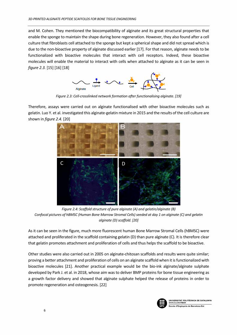
molecules will enable the material to interact with cells when attached to alginate as it can be seen in
figure 2.3. [15] [16] [18]
Figure 2.3: Cell-crosslinked network formation after functionalising alginate. [19]
Therefore, assays were carried out on alginate functionalised with other bioactive molecules such as
gelatin. Luo Y. et al. investigated this alginate-gelatin mixture in 2015 and the results of the cell culture are
shown in figure 2.4. [20]
Figure 2.4: Scaffold structure of pure alginate (A) and gelatin/alginate (B)
Confocal pictures of hBMSC (Human Bone Marrow Stromal Cells) seeded at day 1 on alginate (C) and gelatin
alginate (D) scaffold. [20]
As it can be seen in the figure, much more fluorescent human Bone Marrow Stromal Cells (hBMSC) were
attached and proliferated in the scaffold containing gelatin (D) than pure alginate (C). It is therefore clear
that gelatin promotes attachment and proliferation of cells and thus helps the scaffold to be bioactive.
Other studies were also carried out in 2005 on alginate-chitosan scaffolds and results were quite similar;
proving a better attachment and proliferation of cells on an alginate scaffold when it is functionalized with
bioactive molecules [21]. Another practical example would be the bio-ink alginate/alginate sulphate
developed by Park J. et al. in 2018, whose aim was to deliver BMP proteins for bone tissue engineering as
a growth factor delivery and showed that alginate sulphate helped the release of proteins in order to
promote regeneration and osteogenesis. [22]
C D

3D-PRINTED ALGINATE-PEPTIDE SCAFFOLDS FOR BONE TISSUE ENGINEERING
7
2.4. RGD-Peptide
Peptides are chains composed of several amino acids linked together by amide bonds.
In this project, the focus will be done on the arginylglycylaspartic acid (RGD) that can be seen in figure 2.5.
It is one of the most common peptides in terms of supporting cell adhesion and proliferation thanks to its
combination of 3 amino acids: Arginine, Glycine and Aspartate. [23]
Figure 2.5: RGD peptide molecule.
The use of this motif is quite recent as solid-phase peptide synthesis were achieved only in 1959 and the
identification of the RGD sequence discovered in 1984. It is in part for this reason that in the beginning of
TE, only proteins such as fibronectin or collagen were coated on biocompatible polymers in order to give
bioactivity to the scaffold. But there were some drawbacks in the use of proteins: they need to be isolated
as they can create undesirable immune responses. Also, their application is limited in time because they
need to be refreshed continuously because of their self-degradation. Over time, these problems were
solved thanks to the use of peptides and their motifs attracting cell receptors, that possess better general
stability in the ECM. [23]
Concerning previous studies about RGD scaffolds, a study was performed using RGD-functionalized
polyurethane scaffolds by A. Tahlawi et al., showing great results in term of osteogenic differentiation.[24]
Another study was also carried out in 2012 by W-B. Tsai et al. conjugating this time RGD with chitosan.
They proved lots of benefits that bring the fact of adding RGD in a scaffold such as promoting cell adhesion
and proliferation but also osteogenic differentiation and mineralization and some of the results are shown
in figure 2.6. [25] [26]
Figure 2.6: Calcium deposition by MSCs on chitosan unmodified, azido-modified and conjugated with RGD after 14
days (A) and density of cells attached on the same type of samples (B). [26]
Aspartate Arginine
Glycine
A B

3D-PRINTED ALGINATE-PEPTIDE SCAFFOLDS FOR BONE TISSUE ENGINEERING
8
For example, the results showed above reveal the excellent mineralization properties of RGD, as it
allowed a better calcium deposition (figure 2.6.A). It also promoted a better cell attachment and
proliferation (figure 2.6.B) as showed by a higher density of cells on a chitosan-RGD surface than on pure
chitosan at day 1 as well as at day 14. But these cellular concepts will be explained more clearly in the
bioactivity part of the report.
2.4.1. Bio-Functionalisation of alginate with RGD
As previously said, alginate will be bio-functionalised with the RGD motif peptide with the goal of
mimicking the bones ECM, giving to the scaffold the bioactivity that was not initially present. An interesting
aspect of the RGD molecule is its ease to react with hydroxyl, amino and carboxylic groups. In our case for
example, it will be useful as alginate has carboxylic groups. Indeed, the reaction occurring between
alginate and peptide with the help of EDC activator is shown in figure 2.7 (reaction I) and leads to the 2
reactants linked by an amide bond which represents our bio-functionalised product. However, a
secondary reaction appears and is basically the hydrolysis (reaction II) of the primary product o-
Acylisourea Intermediate into alginate because of the water present in the solution. The fact is that this
secondary reaction is way more stable than the one desired. A third reaction (reaction III) will then be
artificially added thanks to the NHS chemical in order to produce an amine reactive ester that will then
react with the nitrogen of the peptide. The EDC/NHS chemical is therefore compulsory to achieve a good
performance of the functionalisation. [25] [27]
Figure 2.7: Functionalisation reaction of alginate with a peptide linked with an amide group. [28]
This reaction was already studied and optimized in 1999 by Mooney et al. thanks to several experiments
with various parameters (pH, concentration, activation etc.). Culture cells were also carried out on alginate
and RGD modified alginate surfaces and the results are shown in figure 2.8. [29]
I
II
III Alginate
Peptide

3D-PRINTED ALGINATE-PEPTIDE SCAFFOLDS FOR BONE TISSUE ENGINEERING
9
Figure 2.8: Myoblast cells adherent to control alginate surface (A) and RGD modified alginate surface (B) at 4h post-
seeding. [29]
Almost no myoblast adhesion was observed on the control surface whereas the alginate modified with
peptide seems much more attractive for cells because they look well attached and began even spreading
only 4h after seeding. The absence of cells confirms the fact that alginate is not bioactive as it can be seen
in the figure 2.8.a whereas the surface showed in figure 2.8.b react with cells. These results proved then
the presence of RGD peptide on the surface and so highlight the fact that the crosslinking protocol worked.
[29]
2.4.2. Bioactivity
Thanks to RGD motif bioactivity, which means its ability to interact with living tissues, it has been shown
in 2003 by Huang H and his colleagues that the RGD sequence plays a significant role in cell attachment
and proliferation. In addition, these results confirm the ones found by Mooney and co that are discussed
just above. Moreover, when it is incorporated within a scaffold, this peptide sequence may also bring
osteogenic differentiation and mineralization. The first means an ability to self-renew for cells and the
capacity to multiply itself in several type of cells. Indeed, stem cells can differentiate themselves in
osteogenic cells (osteoblasts), cartilage cells (chondrocyte), etc. as it can be seen in figure 2.9 but in the
case of the RGD motif, it will enhance the transformation of stem cells into osteogenic one. Concerning
the mineralization property, it consists of secretion of mineral ions such as calcium in the ECM so cells can
bind to each other and proliferate. [29] [30] [31]
Figure 2.9: Cell differenciation. [32]
A B
3D-PRINTED ALGINATE-PEPTIDE SCAFFOLDS FOR BONE TISSUE ENGINEERING
10
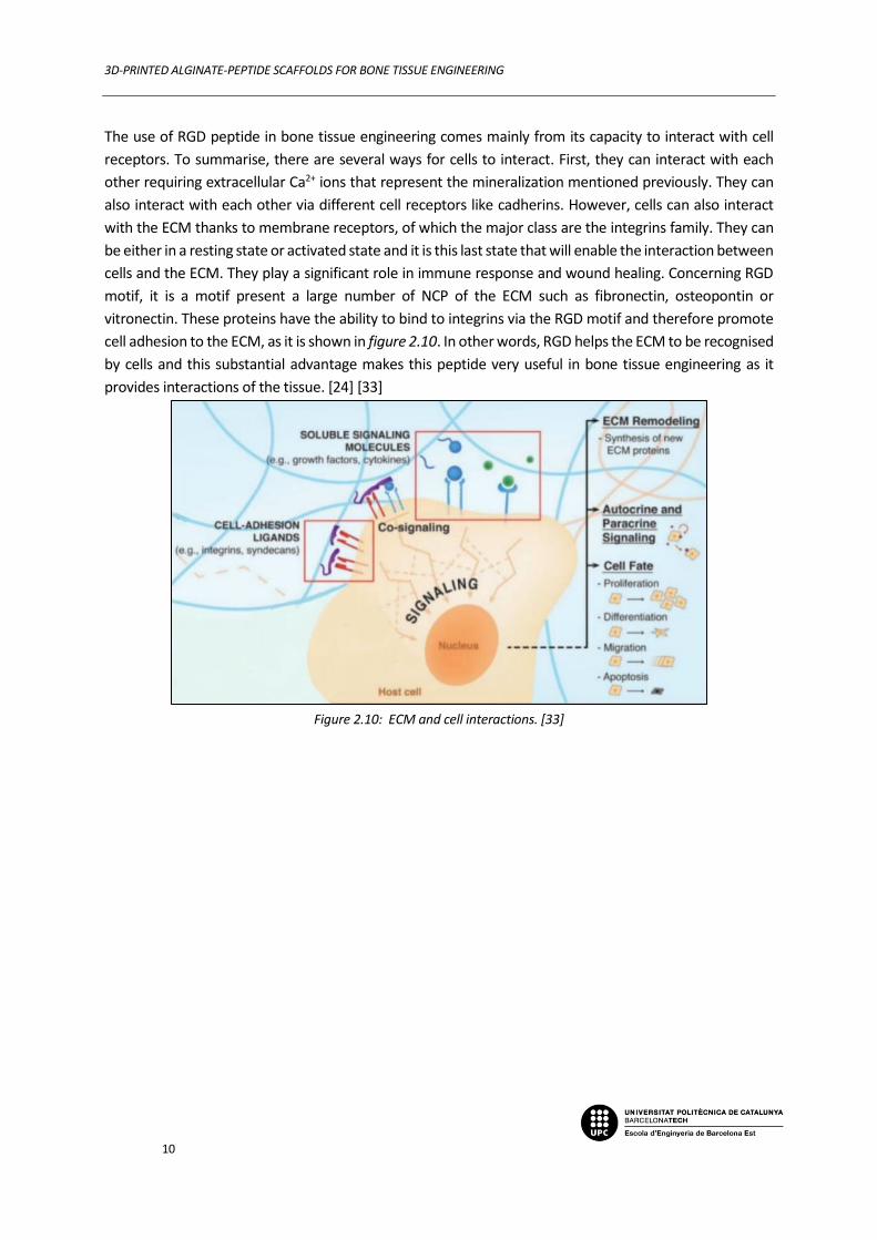
The use of RGD peptide in bone tissue engineering comes mainly from its capacity to interact with cell
receptors. To summarise, there are several ways for cells to interact. First, they can interact with each
other requiring extracellular Ca2+ ions that represent the mineralization mentioned previously. They can
also interact with each other via different cell receptors like cadherins. However, cells can also interact
with the ECM thanks to membrane receptors, of which the major class are the integrins family. They can
be either in a resting state or activated state and it is this last state that will enable the interaction between
cells and the ECM. They play a significant role in immune response and wound healing. Concerning RGD
motif, it is a motif present a large number of NCP of the ECM such as fibronectin, osteopontin or
vitronectin. These proteins have the ability to bind to integrins via the RGD motif and therefore promote
cell adhesion to the ECM, as it is shown in figure 2.10. In other words, RGD helps the ECM to be recognised
by cells and this substantial advantage makes this peptide very useful in bone tissue engineering as it
provides interactions of the tissue. [24] [33]
Figure 2.10: ECM and cell interactions. [33]
3D-PRINTED ALGINATE-PEPTIDE SCAFFOLDS FOR BONE TISSUE ENGINEERING
11
2.5. 3D-printing / bioinks
3D printing is an additive manufacture developed during the 1980’s and consists of printing successive
layers of one of multiple materials and deposited on top of each other with a print-head. These materials
are printed in the form of inks, mixtures mainly formed by the functional material, a resin and a vehicle.
These inks have to flow under moderate pressure and then maintain their shape during and after printing.
This process in appearance quite simple enables the creation of really complicated and precise shape
pieces. There exist many ways to 3D-print an object such as laser melting or laser sintering but in this
project the materials extrusion method will be used. [34]
As it is a quite novel technique, its applications in the biomedical field was quite rare during the last
decades. However, it has been growing a lot in recent years especially in TE. Indeed, thanks to its ability to
print thin filaments, this process enables creation of precise and complex shapes and geometries but also
provide an excellent control of porosity. In the case of scaffolds, porosity and size of pores are really
important parameters to control in order to maximize bone formation and enhance vascularization.
Moreover, this additive manufacture has also the advantage of being quick and so, many printing tests
can be done in a short time. [34]
However, in the case of bone tissue engineering, the use of bioinks is required. Indeed, as the scaffold will
be inserted in the human body, the ink will be made to mimic the biological properties of the target tissue
but also its mechanical properties. Therefore, bioinks will be used and are defined as inks containing
biomaterials and living cells introduced before the printing step. Hydrogel-based bioinks that will be used
in this project are typically biocompatible, biodegradable and have cell-binding sites in order to enhance
attachment, differentiation and proliferation. They are in general made of biomaterials such as natural
polymers (alginate, gelatin, collagen, hyaluronic acid, etc.) but synthetic ones are also used (PEG, PU,
polyacrylamide). [35]

3D-PRINTED ALGINATE-PEPTIDE SCAFFOLDS FOR BONE TISSUE ENGINEERING
12
2.6. Objectives
The main objective of this project is to develop RGD-functionalised alginate bioinks for bone tissue
regeneration. It will be divided on 2 parts:
The first is the functionalisation of the alginate with RGD motif peptide. To do it properly, the
functionalisation protocol will be done several times and improved thanks to data found in the literature
and results of physico-chemical (FTIR, XPS, Confocal Microscopy, etc.) and biological (Cell culture:
attachment and proliferation) characterisations that will be carried out on 2D biofilms to evaluate the
efficiency of the crosslinking protocol and verify the presence of RGD peptide
The second consists of preparing and optimizing bioinks for 3D-printing. In other words, incorporating cells
in the hydrogel and then printing scaffolds before the last step of physic-chemical / biological
characterisation.
RGD crosslinked alginate was studied by several researchers during the 21st century. Finally, printing the
combination of alginate and RGD-peptide was only studied in 2014 by Jia Jia et al., however the scaffold
developed were made in 2D as it can be seen in figure 2.11, deposed onto a calcium substrate in order to
crosslink the bio ink but without using a 3D-printer. [36]
Figure 2.11: shape of the scaffold made in 2014. [36]
As 3D-printing is a quite novel process invented in the beginning of the century, the interest of the study
will be to succeed creating RGD-peptide crosslinked alginate bio inks, but this time, printing the material
in 3D to create a scaffold that can be inserted in the human body in order to provide bone regeneration.
3D-PRINTED ALGINATE-PEPTIDE SCAFFOLDS FOR BONE TISSUE ENGINEERING
13
3. Methods
3.1. Alginate functionalisation with RGD-peptide
3.1.1. First protocol
The first step of the ink preparation is to crosslink the alginate with the RGD-peptide thanks to the
EDC/NHS chemistry with the reaction previously shown in figure 2.7.
- The alginate used in this project is a powder of sodium alginate medium viscosity with a monomer
molecular weight of 198,1 g/mol that leads to chains from 10 000 g/mol to 600 000 g/mol. That alginic
acid sodium salt used comes from the brand Panreac.
- The peptide is an H-Gly-Gly-Gly-Gly-Arg-Gly-Asp-Ser-Pro-OH motif with a molecular weight of 758,74
g/mol per motif and a chemical formula of C28H46N12O13. The sequence of 4 glycine is used as a spacer in
order to promote attachment and Ser-Pro is a sequence that appear many times in proteins such as
fibronectin, so it enhances the activity and the attachment to the ECM.
- The Phosphate Buffered Saline (PBS) solution comes from a tablet of Gibco brand dissolved in 500mL of
distilled water.
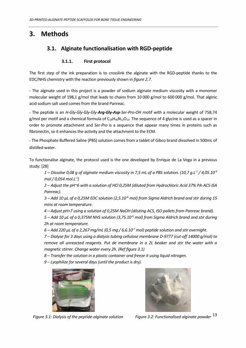
To functionalise alginate, the protocol used is the one developed by Enrique de La Vega in a previous
study: [28]
1 – Dissolve 0,08 g of alginate medium viscosity in 7,5 mL of a PBS solution. (10,7 g.L-1 / 4,05.10-4
mol / 0,054 mol.L-1)
2 – Adjust the pH~6 with a solution of HCl 0,25M (diluted from Hydrochloric Acid 37% PA-ACS-ISA
Panreac).
3 – Add 10 µL of a 0,25M EDC solution (2,5.10-6 mol) from Sigma Aldrich brand and stir during 15
mins at room temperature.
4 – Adjust pH>7 using a solution of 0,25M NaOH (diluting ACS, ISO pallets from Panreac brand).
5 – Add 10 µL of a 0,375M NHS solution (3,75.10-6 mol) from Sigma Aldrich brand and stir during
2h at room temperature.
6 – Add 220 µL of a 2,267 mg/mL (0,5 mg / 6,6.10-7 mol) peptide solution and stir overnight.
7 – Dialyse for 3 days using a dialysis tubing cellulose membrane D-9777 (cut-off 14000 g/mol) to
remove all unreacted reagents. Put de membrane in a 2L beaker and stir the water with a
magnetic stirrer. Change water every 2h. (Ref figure 3.1)
8 – Transfer the solution in a plastic container and freeze it using liquid nitrogen.
9 – Lyophilize for several days (until the product is dry).
Figure 3.1: Dialysis of the peptide-alginate solution Figure 3.2: Functionalised alginate powder

3D-PRINTED ALGINATE-PEPTIDE SCAFFOLDS FOR BONE TISSUE ENGINEERING
14
And the amount of reactants chosen is the following according to data found in literature:
The amount of EDC added was such that 0,61% of the carboxylic acid groups were activated
The ratio EDC/NHS is 1:1
The amount of peptide added is 6,25 mg of peptide per gram of alginate
At the end, the product obtained is a sort of foam that can be seen in figure 3.2.
3.1.2. Final protocol
After some physical and chemical characterisations carried out that will be explained later, the results
revealed an underperformance of the crosslinking. That’s why the protocol was improved thanks to some
results found in the literature and especially by Mooney et al. [29]
1 – Dissolve 0,08 g of alginate medium viscosity in 7,5 mL of a PBS solution.
(10,7 g.L-1 / 4,05.10-4 mol / 0,054 mol.L-1)
2 – Adjust the pH~6 with HCl 1M.
3 – Mix 82 µL of a 0,25M EDC solution (2,05.10-5 mol) with 136 µL of a 0,375M NHS solution
(5,10.10-5 mol) and stir during 15 mins.
4 – Adjust pH>7 using a solution of NaOH 0,25M.
5 – Add 220 µL of a 2,267 mg/mL (0,5 mg / 6,6.10-7 mol) peptide solution and stir overnight.
6 – Dialyse for 4 days using a dialysis tubing cellulose membrane D-9777 (cut-off 14000 g.mol-1) to
remove all unreacted reagents. Put de membrane in a 2L beaker and stir the water with a
magnetic stirrer. Change water every 2h. Ref figure 3
7 – Transfer the solution in a plastic container and freeze it using liquid nitrogen.
8 – Lyophilize for several days (until the product is dry).
And the amount of reactants chose is the following according to data found in literature:
The amount of EDC added was such that 5% of the carboxylic acid groups were activated
The ratio EDC/NHS is 1:2,5
The amount of peptide added is 6,25 mg of peptide per gram of alginate
The reaction occurring between the alginate and peptide was previously showed in figure 2.7. Concerning
the pH, a low pH is first introduced in order to enhance the activation reaction with EDC and Sulfo-NHS.
Moreover, this low pH is also used because NHS has a low half-life in basic pH (4-5 hours at pH 7, 1 hour
at pH 8). Then, the pH is increased since the reaction between Sulfo-NHS and primary amines, such as our
peptide, are the most efficient between pH=7 and pH=8.
NB: These 2 protocols were carried out using RGD peptide but also a fluorescent one in order to characterise the functionalisation thanks to confocal microscopy.

3D-PRINTED ALGINATE-PEPTIDE SCAFFOLDS FOR BONE TISSUE ENGINEERING
15
3.2. 2D-Films protocol
3.2.1. First protocol
To characterise the functionalisation previously done, the use of films is required in order to carry XPS,
confocal microscopy and cell culture characterisations. Therefore, assays of film making protocols were
carried out with only alginate in order to improve the quality of films without wasting expensive peptide.
Therefore, 1,5g of alginate was mixed in 50mL of water and introduced in the SpeedMixerTM (DAC 150.1
FVZ) for 3 times 5 min at 3500 rpm. After that, 1,5mL of this 1,5% w/v alginate solution was dropped off
in a 9cm diameter petri dish plate and then crosslinked 15 mins with calcium chloride 150mM
(110,98g/mol Sigma-Aldrich) in order to form the film. Finally, the films were washed with PBS (3 times)
in order to remove the remaining ions before cutting and drying them.
Figure 3.3: Scheme of the preparation of films. Protocol 1.
3.2.2. Improved protocol
As some problems were shown such as break or degradation of films during films manipulation, some
modifications of the protocol were tested such as increasing the crosslinking time or increasing the volume
added in the petri dish plate (2,5mL / 5mL / 10mL) to get thicker films. Also, the weight concentration was
changed (3% w/v) and assays controlling water evaporation before the crosslinking step in order to get
denser films were carried out.
At the end, the final protocol chosen consists of putting 5mL of a 3% w/v alginate solution (3g of alginate
in 50mL of water introduced in the SpeedMixerTM (DAC 150.1 FVZ) for 3 times during 5 min at 3500 rpm)
in a 9 cm diameter petri plate. Then, the alginate is crosslinked during 1h with CaCl2 150mM. Finally, the
films were washed with water (PBS degrades the films) for 3 times before cutting and drying them.
3.3. CELL CULTURE
The cell culture is the most important characterisation of this project as it enables to quantify the
bioactivity of the scaffold and the presence of peptide. The protocol is the following:
I) CLEANING. First, cleaning the hood and the materials with ethanol is necessary in order to avoid
contamination. Ethanol is also used to sterilize the films before starting any other manipulations.
Alginate (functionalized or not)
1,5 % w/v
1,5mL 9cm
CaCl2 150mM
PBS wash 3x Cut and dry
Crosslinking

3D-PRINTED ALGINATE-PEPTIDE SCAFFOLDS FOR BONE TISSUE ENGINEERING
16
II) PREPARATION OF THE MEDIA. Dulbecco/Vogt modified Eagle's minimal essential medium (DMEM) is
mixed with a buffer: 4-(2-hydroxyethyl)-1-piperazineethanesulfonic acid (HEPES) to maintain physiological
pH. Then L-glutamine and penicillin antibiotics are added to prevent bacterial infections. Moreover, 2
medias are elaborated, one with Fetal Bovine Serum (FBS) to enhance attachment and one without. The
recipes are the following:
III) PREPARATION OF CELLS. As MG63 cells are agglomerated at the bottom of the falcon, the media is
taken off. Then, a rinse with PBS is required to take off completely the media and 2mL of trypsin is used
to detach the cells. However, as trypsin is active only at 37°C, it had to be put in the incubator. After that,
the trypsin is neutralised with 4mL of media with FBS and taken off after 5min centrifugation at 300
Relative Centrifugal Force (RCF).
IV) CELL COUNTING. For this step, 3mL of each media is mixed with cells thanks to a vortex. Then, 10 µL
of these solutions is taken off and put on a Neubauer chamber. After counting thanks to a microscope, the
media is once again diluted depending on the previous counting, in order to obtain a concentration of
50 000 cells per mL.
Then, the next steps depend on the type of cell culture wanted: attachment or proliferation
ATTACHMENT PROLIFERATION
V) CELLS SITTING. 0,5mL of media is added in the
plate for each film (25 000 cells). Then, they are kept
in the incubator (37°C) for 6h.
VI) FIXATION OF THE CELLS. Films are washed 1 time
with PBS and then are fixated with 300 µL of a 4%
solution of Perfluoroalkoxy Polymer (PFA) during 15
mins. Finally, films are washed 3 times with PBS.
VII) PERMEABILISATION. Alexa fluor 546 phalloidin is
mixed with a permeabilization solution (triton X-100
1:2000 PBS) in 1:300 proportion. The PBS is removed
and 250 µL of this solution is added in the plate of
each film during 1h.
V) CELLS SITTING. 0,5mL of media is added in the plate
for each film (25 000 cells). Then, they are kept in the
incubator (37°C) for 4h. After that, the media is removed
and an Alamar blue cell viability agent 1:10 Media
solution is added at a quantity of 350 µL for each film for
1h.
VI) CALIBRATION CURVE. In order to interpret the results
and correlate number of cells and fluorescence, a
calibration curve is required. To do so, the cells sitting
solution is added in several plates with different number
of cells (2 500 to 80 000) at an amount of 350 µL and kept
during 1h30 in the incubator. Then, the plates are put in
a BioTek plate reader (model Synergy HTX) to quantify
DMEM – 43mL (86%)
FBS – 5mL (10%)
HEPES – 1mL (2%)
L-glutamine – 0.5mL (1%)
Penicillin – 0,5mL (1%)
DMEM – 48mL (96%)
HEPES – 1mL (2%)
L-glutamine – 0.5mL (1%)
Penicillin – 0,5mL (1%)
3D-PRINTED ALGINATE-PEPTIDE SCAFFOLDS FOR BONE TISSUE ENGINEERING
17
The phalloidin will stain the betectine filament
(cytoskeleton) of the cells. But as it is a big molecule,
permeabilization with triton is required so it can pass
through. Concerning alexa fluor, it is used to see the
cells at the confocal.
VIII) FLUORESCENCE OF THE NUCLEI. 250 µL of DAPI
solution is added in each plate containing a film
which is basically a solution of DAPI 1:1000 washing
solution (glycine 1:666 PBS)
Finally, films are ready to be observed at confocal
microscopy to be characterised.
the fluorescence and correlate it with the cells number.
Then, the curve can be drawn.
VII) RESULTS. To obtain the results, the plate is stocked in
an incubator and put each day in the plate reader to know
the fluorescence and so, thanks to the calibration curve,
know the number of cells and their proliferation rate. The
results are converted in number of cells per mm² because
several diameters were used:
Cover sleep D = 11,7 mm Alginate D = 6,3 mm RGD-Alginate D = 6,3 mm
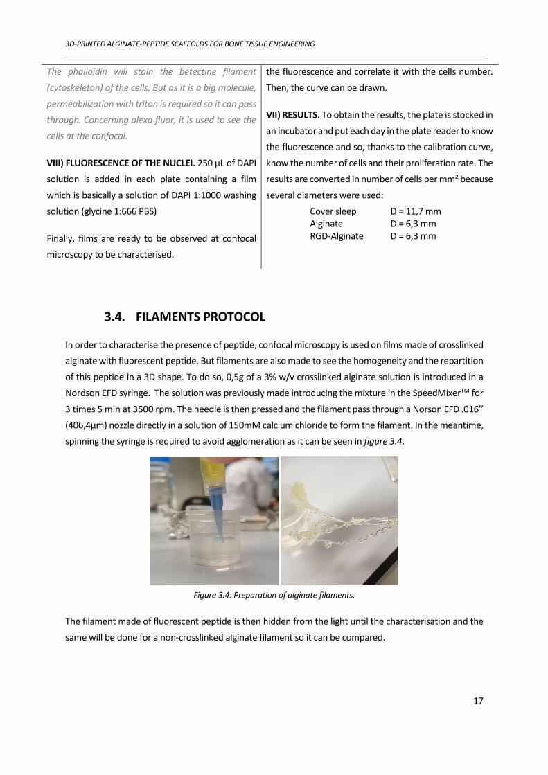
3.4. FILAMENTS PROTOCOL
In order to characterise the presence of peptide, confocal microscopy is used on films made of crosslinked
alginate with fluorescent peptide. But filaments are also made to see the homogeneity and the repartition
of this peptide in a 3D shape. To do so, 0,5g of a 3% w/v crosslinked alginate solution is introduced in a
Nordson EFD syringe. The solution was previously made introducing the mixture in the SpeedMixerTM for
3 times 5 min at 3500 rpm. The needle is then pressed and the filament pass through a Norson EFD .016’’
(406,4µm) nozzle directly in a solution of 150mM calcium chloride to form the filament. In the meantime,
spinning the syringe is required to avoid agglomeration as it can be seen in figure 3.4.
Figure 3.4: Preparation of alginate filaments.
The filament made of fluorescent peptide is then hidden from the light until the characterisation and the
same will be done for a non-crosslinked alginate filament so it can be compared.
3D-PRINTED ALGINATE-PEPTIDE SCAFFOLDS FOR BONE TISSUE ENGINEERING
18
Alginate and functionalised alginate filaments filled with cells were also elaborated:
- First, the powder and all toolds used such as syringes, nozzles and pots were sterilized with ethanol.
- Two pots were filled with 750µL of media and with respectively 0,03g of pure alginate and 0,03g of
functionalised alginate.
- The solutions are mixed thanks to the speed mixer (3 times 5 minutes at 3500 rpm).
- 250µL of media is then added to each pot with 1 million cells inside. The cells were before counted thanks
to a Neubauer chamber and then diluted to obtain the correct amount. After that, the mixture is mixed
by hand to keep cells alive.
- Finally, solutions are put in syringes and pressed into a calcium chloride (150mM) bath to be crosslinked.
Then, cells need to be stained in order to carry out a life/dead assay. To do so, a staining solution is
elaborated using 3,5mL of DMEM, 10,5µL of calcein solution (green staining for all cells) and 3,5µL of
propidium iodide solution (red staining for dead cells). 0,5mL of staining solution is put in each plate during
5 minutes. Finally, the samples are ready to be analysed with LCSM at day 0,1,3,7 and 14, keeping them
in the incubator between each characterisation.
3.5. CARACTERISATION METHODS
3.5.1. Fourier Transform InfraRed (FTIR)
Fourier Transform InfraRed (FTIR) spectroscopy is a technique that enables to analyse solids (powder, film,
etc.) and liquid samples and identify their functional groups. Basically, a polychromatic infrared beam is
introduced onto an optically dense crystal (Germanium) that reflect the infrared beam onto the samples
and thanks to their different absorbance and transmittance properties at different wavelengths, an IR
spectrum is obtained. This spectrum shows the transmittance of the material according to the
wavenumber (cm-1) and so enables to determinate the molecular composition and structure of the
material according to the wavenumber at which are located the peaks and the tables found in the
literature. [37]
The FTIR equipment used in is the spectroscope Thermoscientific Nicolet 6700 and the acquisition of the
data on the OMNIC software. In this case, the characterisation of pure alginate and functionalised alginate
powder after freezing and lyophilisation were carried out using a resolution of 2 and 512 scans.

3D-PRINTED ALGINATE-PEPTIDE SCAFFOLDS FOR BONE TISSUE ENGINEERING
19
3.5.2. X-Ray Photoelectron spectroscopy (XPS)
X-Ray Photoelectron spectroscopy (XPS) is a photoelectric spectroscopic and non-destructive technique
that enables the measurement of the material elemental composition. The XPS spectrum is drawn after
irradiating the material with an X-rays beam. Indeed, some electrons on the surface of the materials will
be emitted and their emission is analysed. The electrons ejected are counted according to a range of
electron kinetic energies. The peaks will then enable to identify the surface elements. It is a good way to
identify the chemical composition of the samples as all type of materials can be used for this
characterisation. Moreover, this method enables also to analyse the empirical formula, chemical state and
electronic state of the sample’s elements. However, a drawback is that only the surface of the material
can be scanned (up to 10nm). Therefore, the results found are likely not similar to the one in the bulk.
Also, a vacuum is required. [38]
The equipment used in this case is from SPECS Brand (Berlin, Germany) with as a source: a XR50 dual
anode (only the Al anode operating at 200W was used) and as detector: the Phoibos 150 MCD-9 using a
pass energy of 20eV.
The parameters used were: - Vacuum: under 5x10⁻⁹ mbar
- Survey: 0.1eV/step, 3 scans
- High resolution spectra: 0.05eV/step, 5 scans
3.5.3. Laser Confocal Scanning Microscopy (LCSM)
Laser Confocal Scanning Microscopy (LCSM) is a technique widely used to detect fluorescence. The
difference with other fluorescence techniques is its ability to detect only fluorescent light that is close to
the focal plane thanks to a focused laser beam that produces spot illumination on the sample, this is why
it is possible to remove the background glow and so having great quality and resolution of images. At the
end, by combining every optical plane, it is possible to produce a 3D image. This technique is mostly used
in biology and medicine to evaluate several eye diseases or to detect molecular, cells and proteins
interactions. Finally, no sample preparation is required but for high resolutions such as 63X, oil immersion
is required. [39]
Fluorescence images were obtained with the equipment Zeiss LSM 800 using 5x, 10x and 63x objectives
(the higher one requiring oil immersion). The acquisition of images was done using Zen 2.3 software from
Zeiss company and modified using ImageJ software.

3D-PRINTED ALGINATE-PEPTIDE SCAFFOLDS FOR BONE TISSUE ENGINEERING
20
4. RESULTS AND DISCUSSIONS
4.1. 1st functionalisation protocol
4.1.1. FTIR
As it was previously said, the first protocol carried out was the one used by a previous student Enrique de
Vega GOMEZ, the protocol is explained in the method part. [28] After the last step of lyophilisation, the
powder collected has been compared to pure alginate thanks to FTIR characterisation, the results are
shown in figure 4.1 and 4.2.
Figure 4.1: FTIR spectrum of alginate.
Figure 4.2: FTIR spectrum of functionalized alginate from 1st protocol.
The FTIR did not show any significant results. Indeed, only small changes in the spectrum could be noticed
such the peak of the C-H bond (2850-3000 cm-1) shown with red arrows that is more distinct for the
functionalised powder (fig 4.2) than the pure alginate (fig 4.1). Moreover, a C=O peak (1750-1800) shown
with blue arrows can be recognised in figure 4.2 and cannot be seen with pure alginate. These results
91,0092,0093,0094,0095,0096,0097,0098,0099,00100,00101,00
7001 2001 7002 2002 7003 2003 700
Alginate
94,00
95,00
96,00
97,00
98,00
99,00
100,00
7001 2001 7002 2002 7003 2003 700
PEPTIDE ALGINATE
Transmittance (%)
Wavenumbers (cm-1)
Transmittance (%)
Wavenumbers (cm-1)

3D-PRINTED ALGINATE-PEPTIDE SCAFFOLDS FOR BONE TISSUE ENGINEERING
21
show a difference in the molecular architecture between the 2 powders. However, the difference of peak
intensity is quite small and only a few percentages of transmittance differ. This is why it is impossible to
conclude about the performances of the crosslinking without carrying other characterisation techniques
such as a biological one.
4.1.2. Cell culture
Another characterisation method carried out is cell attachment. After achieving the elaboration of 2D
biofilms according to the first protocol, a cell adhesion protocol was carried out on functionalised alginate
films, alginate reference films and coverslips using media with and without FBS. But once again, the results
were mixed. Indeed, some cells were attached on the bottom but almost none on the top of the films.
There were no significant differences between functionalised and non-functionalised films and the few
cells attached kept a round shape which means that they were badly attached. As a conclusion, almost no
bioactivity was observed and these results lead to the fact that there is a problem in the functionalisation
and show an insufficient quantity of peptide in the biofilm. That’s why the first functionalisation protocol
has been improved into the final one thanks to results found in the literature.
Another problem of this cell culture assay was the difficulty to manipulate the films and sometimes their
degradation. That’s why it was impossible to take pictures of this assay. At the end, the first film
elaboration protocol also needed to be improved into the final one shown in the method part in order to
achieve making stiffer films that would be easier to manipulate and so to characterise.

3D-PRINTED ALGINATE-PEPTIDE SCAFFOLDS FOR BONE TISSUE ENGINEERING
22
4.2. 2nd functionalisation protocol
4.2.1. FTIR
FTIR technique was also carried out for the final protocol, the results found are shown in figure 4.3 and
4.4.
Figure 4.3: FTIR spectrum of algina
Figure 4.4: FTIR spectrum of functionalized alginate from 2nd protocol.
Once again, no significant result was found. Indeed, the small C-H bond (2850-3000 cm-1) shown with red
arrows completely disappeared in figure 4.4. In addition, the C=O peak (1750-1800) shown with blue
arrows was present in the spectrum of the functionalised alginate from the first protocol (fig 4.2) but is
here quite hard to recognise. At the end, the conclusion is similar to the last FTIR characterisation, a
molecular structure change is recognised but the differences being too little, it is impossible to draw
conclusions of this assay. Indeed, either the functionalisation could have not worked or the amount of
peptide could be too little compared to the amount of alginate so the difference would be hard to seen
with FTIR. This is why other characterisation techniques are required.
91,0092,0093,0094,0095,0096,0097,0098,0099,00100,00101,00
7001 2001 7002 2002 7003 2003 700
Alginate
92,00
93,00
94,00
95,00
96,00
97,00
98,00
99,00
100,00
7001 2001 7002 2002 7003 2003 700
Alginate - Peptide
Transmittance (%)
Wavenumbers (cm-1)
Transmittance (%)
Wavenumbers (cm-1)

3D-PRINTED ALGINATE-PEPTIDE SCAFFOLDS FOR BONE TISSUE ENGINEERING
23
4.2.2. XPS
XPS was carried out using 2 functionalised films and 2 references made with pure alginate. The
elements of the analysis included C, O and N. The analysis of the N signal was particularly interesting
as this element is only found in the peptides. However, as detailed in Table X, no differences were
observed between alginate and alginate functionalized with RGD in the chemical composition at the
atomic level. As explained in the previous characterisation FTIR, the amount of RGD peptide used is
very low compared to alginate. Therefore, it is complicated to detect any composition differences as it
can be seen in figure 4.5. The table used to draw this graph can be found in annex (table A).
Figure 4.5: Graph of XPS results showing films atom composition.
However, significant differences were found when the C1s peak was deconvoluted into its main
components, as it can be seen in figure 4.6. The table used for this graph is in the annex part (table B).
Figure 4.6: XPS results graph for the deconvolution of the C1s peak at different binding energies.
Interestingly, quantitative changes are noticeable in the composition of the C1s components, as
evidenced by the different % obtained for the distinct binding energies of C1s. This means that even if
the peptide cannot be detected, its presence changes the chemical architecture of alginate. Thus, XPS
results indirectly support the success of the grafting procedure.
0
10
20
30
40
50
60
70
80
90
C N O
Ato
mic
co
mp
osi
tio
n (
%)
Alginate
Alginate-RGD
0,0
10,0
20,0
30,0
40,0
50,0
60,0
283 284-285 286 288
C1
s d
eco
nvo
luti
on
(%
)
Binding energy (eV)
Alginate
Alginate-RGD
3D-PRINTED ALGINATE-PEPTIDE SCAFFOLDS FOR BONE TISSUE ENGINEERING
24
4.2.3. LCSM
4.2.3.1. 2D films
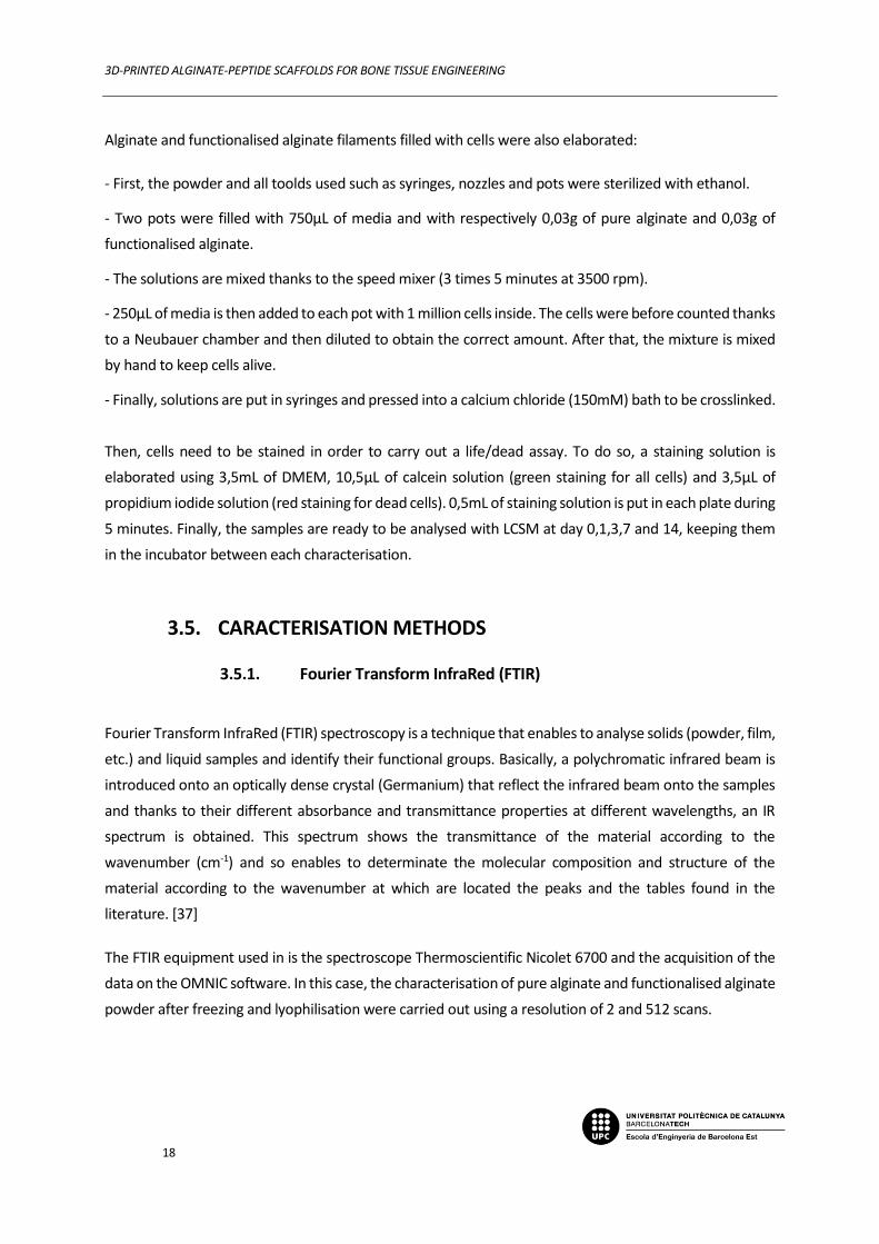
As FTIR and XPS results didn’t put in evidence the presence of peptide, the crosslinking protocol was
also carried out with fluorescent peptide. Then 2D biofilms were made in order to be characterised by
confocal microscopy. The results are shown in figure 4.7.
Figure 4.7: CLSM images of 3% w/v films of alginate at 10x (a), 63x (c) and
Fluorescent RGD functionalised alginate at 10x (b) and 63x (d)
With the purpose of analysing the presence of RGD, green fluorescence and borders delimitations of
figure 4.7(b) show the presence of peptide. As the reference (a) show no fluorescence, the results
shown do not come from background but from a good functionalisation of the alginate with the RGD
motif. The assay also shows a much higher fluorescence of the functionalised alginate (d) at higher
magnitude than non-functionalised alginate (c). Concerning the green points present in figure 4.7(c),
they come from background fluorescence.
a b
c d

3D-PRINTED ALGINATE-PEPTIDE SCAFFOLDS FOR BONE TISSUE ENGINEERING
25
4.2.3.2. 3D filaments
Even if the results of this LCSM assay were quite encouraging, the same characterisation was carried
out on 3D filaments to be sure of the homogeneity and the repartition of the peptide in the hydrogel.
The results found are shown in figure 4.8.
Figure 4.8: CLSM images of 3% w/v filaments of alginate at 5x (a), 63x (c) and
Fluorescent RGD functionalised alginate at 5x (b) and 63x (d)
At low magnitude, it is clear that RGD functionalised filament (fig 4.8(b)) is much more fluorescent than
the alginate one (a) and so contain the fluorescent peptide. Moreover, even though some
agglomerations can be seen at different places of the sample, the repartition of the peptide seems
quite homogeneous. Same results were found at 63x magnitude, alginate filament (c) appears without
any fluorescence whereas the functionalised one (d) show clearly fluorescence. Also, the border of the
filament is well defined as it can be seen in figure 4.8(d) by the drew orange line.
a b
c d

3D-PRINTED ALGINATE-PEPTIDE SCAFFOLDS FOR BONE TISSUE ENGINEERING
26
4.2.4. Cell culture on 2D films
As the last assay proved the presence of peptide in the hydrogel after the functionalisation protocol, it
is necessary to verify its bioactivity thanks to biological cellular assays.
4.2.4.1. Cell attachment assay
The first assay carried out was a cellular attachment explained in the method part to compare
functionalised alginate with non-functionalised one. The 2D films were made using the improved
protocol.
4.2.4.1.1 Optical Microscopy
After sitting cells (step V), which consists of their deposition and their adhesion on films, optical
microscopy was carried out and the images obtained are shown in figure 4.9.
Figure 4.9: MG63 cells adherent to control alginate surface (a) and RGD modified alginate surface (b) with FBS
and respectively (c) and (d) without FBS at 6h post-seeding.
In figure 4.9.a and 4.9.b, cells are much more spread and this is due to participation of FBS that
possesses cell proliferation properties as it provides many nutrients and growth factor that enhance
a b
c d

3D-PRINTED ALGINATE-PEPTIDE SCAFFOLDS FOR BONE TISSUE ENGINEERING
27
their proliferation. Moreover, without FBS, it is clear that more cells have spread and so proliferated
on functionalised alginate surfaces (a) than on non-functionalised ones (b). The difference is also
noticeable without FBS; indeed, some spread cells can be seen on RGD-modified alginate (d) and are
pointed by white arrows whereas none are distinct on alginate films (c).
As a conclusion of this assay, the results seem quite encouraging and confirming a better bioactivity of
functionalised alginate. To confirm these results, LCSM technique is then used.
4.2.4.1.2 LCSM
After step VIII of the cell culture attachment protocol, cells are already fixed and fluorescent thanks to
Alexa Fluor and DAPI for the nuclei, it enables their visualisation in a confocal microscopy assay. The
pictures taken thanks to LCSM are shown in figure 4.10.
Figure 4.10: CLSM images of 3% w/v films of alginate (a) and RGD modified alginate (b) with FBS
And respectively without FBS (c) and (d) at 6h post seeding.
a b
c d

3D-PRINTED ALGINATE-PEPTIDE SCAFFOLDS FOR BONE TISSUE ENGINEERING
28
In these pictures, blue colour comes from DAPI and represents nuclei of cells and orange/red colour
comes from Alexa fluor and represents the betectine filaments (cytoskeleton) of cells. As in optical
microscopy pictures, cells are much more numerous and spread with FBS (a,b) compared to without
(c,d). An aspect of these results is that, without FBS, no major differences can be recognise between
functionalised alginate (d) and non-functionalised one (c), the number of cells is quite similar and their
spreading seem limited in both figures. However, what is relevant here is the pictures with FBS. It can
easily be noticed that cells are much more spread in presence of RGD (b) than without (a). Several cells
are agglomerated but even the ones that are far from the other are well spread which means that the
surface has bioactive properties and so prove the presence of RGD motif.
At the end, optical microscopy results agree with the LCSM ones and show bioactivity properties of
biofilms as expected.
4.2.4.2. Cell proliferation assay
Cell proliferation assay was then carried out using the protocol described in the method parts. The
results used to draw the calibration curve represented in figure 4.11 are shown in annex (table C-D).
Figure 4.11: Calibration curve of cell proliferation assay.
Then, thanks to this calibration curve, number of cells can be correlated to fluorescence intensity and
the following graphs can be drawn at day 1, 2 and 7 after seeding.
y = 0,1039x - 4852,1R² = 0,9986
0
10000
20000
30000
40000
50000
60000
70000
80000
90000
0 100000 200000 300000 400000 500000 600000 700000 800000 900000
Nu
mb
er o
f ce
lls
Fluorescence Intensity [a.u.]
Calibration curve
3D-PRINTED ALGINATE-PEPTIDE SCAFFOLDS FOR BONE TISSUE ENGINEERING
29
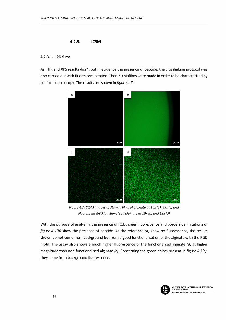
Figure 4.12: Histogram of samples cell density at 1-day post-seeding.
Figure 4.13: Histogram of samples cell density at 2-days post-seeding.
Figure 4.14: Histogram of samples cell density at 7-days post-seeding.
Results of proliferation assay in figure 4.12, 4.13 and 4.14 show globally an enhancement of cell density
over time for functionalised and non-functionalised alginate films. However, no major difference is
noticeable between the 2 samples. Also, presence or absence of FBS do not provide density changes.
So, questions concerning the reliability of these experiments arise. Another unusual fact is that a
diminution of cell density is detected for cover sleep samples which indicates a death of a high number
of cells on control samples. At the end, these results are questioned and an issue in the experimental
0
200
400
600
800
1000
ALG +FBS ALG -FBS RGD +FBS RGD -FBS C +FBS C -FBS
Nu
mb
er o
f ce
lls/m
m2
Cell density 1 day after seeding
0
200
400
600
800
1000
ALG +FBS ALG -FBS RGD +FBS RGD -FBS C +FBS C -FBS
Nu
mb
er o
f ce
lls/m
m2
Cell density 2 days after seeding
0
500
1000
1500
2000
2500
ALG +FBS ALG -FBS RGD +FBS RGD -FBS C +FBS C -FBS
Nu
mb
er o
f ce
lls/m
m2
Cell density 7 days after seeding

3D-PRINTED ALGINATE-PEPTIDE SCAFFOLDS FOR BONE TISSUE ENGINEERING
30
condition or a product contamination is suspected. A repetition of this experience is so required to
exploit the results but not carried out in this project because of lack of time.
However, apart from proliferation results, even if these biological assays seem quite promising,
experiments were carried out on films and so on 2D surfaces of samples. And as this project include
hydrogels, they should normally provide abundant space in their 3D-network for cells to grow. That is
why biological characterisations have to be carried out on 3D-filaments to confirm biofilms results.
However, because of lack of time, it had not been carried out until the end in this study.
4.2.5. Cell culture on 3D filaments
4.2.5.1. Life/dead assay
Life/dead assays were carried out as explained in the methods part and the results at 2h, day 1 and 3
post-seeding are shown in figure 4.1.
Figure 4.15: CLSM images of 3% w/v films of alginate (a,b,c) and RGD modified alginate (d,e,f) at 2h (a,e), day 1
(b,e) and day 3 (c,f) post-seeding.
As seen in figure 4.15, cells seemed viable during the entire incubation period for all conditions.
However, the presence of the peptide did not seem to improve the number of adherent cells. On the
a b c
e d f

3D-PRINTED ALGINATE-PEPTIDE SCAFFOLDS FOR BONE TISSUE ENGINEERING
31
contrary, the number of cells seemed to be reduced on RGD-coated samples, compared to control
alginate.
These results were not as expected; however, the RGD-coated alginate filaments were prepared from
the 2D films previously used during the project and the integrity of the resulting filaments was not
optimal. In fact, the filaments did not seem to be strongly crosslinked and were partially disaggregating.
Thus, the lack of bioactivity could be partially attributed to this handling problems. More experiments
in this regard would be required.
4.2.5.2. Proliferation assay
Proliferation assay was also carried out using the same protocol as for biofilms. The results are shown
in figure 4.16.
Figure 4.16: Histogram of Fluorescence intensity of pure alginate and functionalised alginate filaments 2h, day 1
and 3 post-seeding.
In agreement with the live / dead experiments, it seems that cells are viable in the filaments and in fact
are capable of proliferating. However, the RGD peptide is not showing any positive effects in the
growth of the cells. Here, again, the problems previously commented on the integrity of the filaments
could be the reason for such outcome. Further work is necessary to explain these effects.
0
5000
10000
15000
20000
25000
30000
Alginate RGD-functionalised Alginate
Flu
ore
scen
ce in
ten
sity
[a.
u]
t=0
t=1
t=3

3D-PRINTED ALGINATE-PEPTIDE SCAFFOLDS FOR BONE TISSUE ENGINEERING
32
Conclusions
During this project, RGD functionalised alginate bioinks were developed in order to be 3D printed as
scaffolds for bone TE. To characterise this functionalisation, 2D biofilms were elaborated and their
protocol improved. After carrying assays on these films, difficulties appeared concerning revealing the
presence of peptide using physical and chemical characterisations such as FTIR and XPS techniques.
However biological results on these films revealed presence and usefulness of RGD motif as a bioactive
enhancer especially promoting cell adhesion and cell proliferation. Assays on cell incorporated
filaments were also carried out to confirm the hydrogel biological properties at a 3D scale but no
promising results were shown as some experimental conditions distorted the assay, such as reusing
functionalised RGD. To conclude, the methodology of RGD-modified alginate hydrogel elaboration,
previously unknown by the research group, has been established and optimized but still need some
improvements.
To continue this project, characterisation tests need to be redone in order to confirm the previous
results. But also, further studies carrying other characterisation tests have to be run such as
radiolabelling, radioactivity techniques or cell differentiation markers, to specify the biological
properties of the future scaffold. Moreover, assays on 3D filaments filled with cells have to be redone.
Finally, assays of 3D printing could be run and printing optimisation carried out in order to finish this
study.
3D-PRINTED ALGINATE-PEPTIDE SCAFFOLDS FOR BONE TISSUE ENGINEERING
33
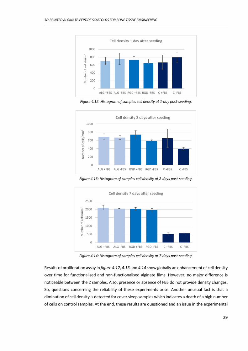
Economic Analysis
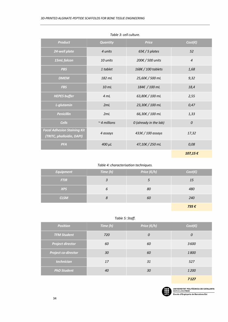
An economic analysis of this project was carried out to estimate its global price. This analysis revealed
the amount of 8 495€ spent in this project. The details are shown in the tables bellow:
First, 6 alginate functionalisation protocol have been performed and their cost is shown in table 1.
Table 1: Alginate functionalisation.
Product Quantity Price Cost(€)
RGD 3 mg 100€ / mg 300
Fluorescent RGD 1,7 mg 100€ / mg 170
Alginic acid sodium salt 0,72 g 31,40€ / 250g 0,09
Distilled water 40 L 0,60€ / L 24
Dialysis membrane 2 m 132,30€ / 30m 8,82
NHS 0,036 g 685€ / kg 0,022
EDC 0,0245 g 374€ / 25g 0,36
PBS 1 tablet 168€ / 100 tablets 1,68
504,97 €
Then films protocol was elaborated and improved many times.
Table 2: Film elaboration.
Product Quantity Price Cost(€)
Alginic acid sodium salt 2 g 31,40€ / 250g 0,25
Distilled water 2 L 0,60€ / L 1,20
Calcium chloride 16,5 g 112€ / 100g 18,48
PBS 1 tablet 168€ / 100 tablets 1,68
21,61 €
3 biological cell attachment and 2 proliferation protocols were then carried out.
3D-PRINTED ALGINATE-PEPTIDE SCAFFOLDS FOR BONE TISSUE ENGINEERING
34
Table 3: cell culture.
Product Quantity Price Cost(€)
24-well plate 4 units 65€ / 5 plates 52
15mL falcon 10 units 200€ / 500 units 4
PBS 1 tablet 168€ / 100 tablets 1,68
DMEM 182 mL 25,60€ / 500 mL 9,32
FBS 10 mL 184€ / 100 mL 18,4
HEPES buffer 4 mL 63,80€ / 100 mL 2,55
L-glutamin 2mL 23,30€ / 100 mL 0,47
Penicillin 2mL 66,30€ / 100 mL 1,33
Cells ~ 4 millions 0 (already in the lab) 0
Focal Adhesion Staining Kit
(TRITC, phalloidin, DAPI) 4 assays 433€ / 100 assays 17,32
PFA 400 µL 47,10€ / 250 mL 0,08
107,15 €
Table 4: characterisation techniques.
Equipment Time (h) Price (€/h) Cost(€)
FTIR 3 5 15
XPS 6 80 480
CLSM 8 60 240
735 €
Table 5: Staff.
Position Time (h) Price (€/h) Cost(€)
TFM Student 720 0 0
Project director 60 60 3 600
Project co-director 30 60 1 800
technician 17 31 527
PhD Student 40 30 1 200
7 127
3D-PRINTED ALGINATE-PEPTIDE SCAFFOLDS FOR BONE TISSUE ENGINEERING
35
Bibliography
[1] Lluis oliver cervello (2019) Design and Synthesis of Bone Morphogenetic Protein (BMP) mimetics to develop novel multifunctional Biomaterials for Bone Regeneration, UPC, 1-20.
[2] Chan, B. P., & Leong, K. W. (2008). Scaffolding in tissue engineering: general approaches and tissue-specific considerations. European Spine Journal, 17(S4), 467–479.
[3] Furth, M. E., & Atala, A. (2014). Tissue Engineering. Principles of Tissue Engineering, 6, 83–123.
[4] Huang, B., Caetano, G., Vyas, C., Blaker, J., Diver, C., & Bártolo, P. (2018). Polymer-Ceramic Composite Scaffolds: The Effect of Hydroxyapatite and β-tri-Calcium Phosphate. Materials, 11(1), 129.
[5] Alaribe, F. N., Manoto, S. L., & Motaung, S. C. K. M. (2016). Scaffolds from biomaterials: advantages and limitations in bone and tissue engineering, 10, 259-275
[6] Tanodekaew, S., Channasanon, S., Kaewkong, P., & Uppanan, P. (2013). PLA-HA Scaffolds: Preparation and Bioactivity. Procedia Engineering, 59, 144–149.
[7] Qu, H., Fu, H., Han, Z., & Sun, Y. (2019). Biomaterials for bone tissue engineering scaffolds: a review. RSC Advances, 9(45), 26252–26262.
[8] Billström, G. H., Blom, A. W., Larsson, S., & Beswick, A. D. (2013). Application of scaffolds for bone regeneration strategies: Current trends and future directions. Injury, 44, 28–33.
[9] Bai, X., Gao, M., Syed, S., Zhuang, J., Xu, X., & Zhang, X.-Q. (2018). Bioactive hydrogels for bone regeneration. Bioactive Materials, 3(4), 401–417.
[10] Slaughter, B. V., Khurshid, S. S., Fisher, O. Z., Khademhosseini, A., & Peppas, N. A. (2009). Hydrogels in Regenerative Medicine. Advanced Materials, 21(32-33), 3307–3329.
[11] Sudhakar, C. K., Upadhyay, N., Jain, A., Verma, A., Narayana Charyulu, R., & Jain, S. (2015). Hydrogels—Promising Candidates for Tissue Engineering. Nanotechnology Applications for Tissue Engineering, 77–94.
[12] Mredha, M. T. I., Kitamura, N., Nonoyama, T., Wada, S., Goto, K., Zhang, X., … Gong, J. P. (2017). Anisotropic tough double network hydrogel from fish collagen and its spontaneous in vivo bonding to bone. Biomaterials, 132, 85–95.
[13] Perez, R. A., Kim, J.-H., Buitrago, J. O., Wall, I. B., & Kim, H.-W. (2015). Novel therapeutic core–shell hydrogel scaffolds with sequential delivery of cobalt and bone morphogenetic protein-2 for synergistic bone regeneration. Acta Biomaterialia, 23, 295–308.
[14] Venkatesan, J., Nithya, R., Sudha, P. N., & Kim, S.-K. (2014). Role of Alginate in Bone Tissue Engineering. Advances in Food and Nutrition Research, 45–57
[15] Lee, K. Y., & Mooney, D. J. (2012). Alginate: Properties and biomedical applications. Progress in Polymer Science, 37(1), 106–126.
[16] The surprising uses of alginate. https://www.artmolds.com/alginate-uses (consulted the 12/12/2019).
[17] Shapiro, L., & Cohen, S. (1997). Novel alginate sponges for cell culture and transplantation. Biomaterials, 18(8), 583–590.
[18] Venkatesan, J., Bhatnagar, I., Manivasagan, P., Kang, K.-H., & Kim, S.-K. (2015). Alginate composites for bone tissue engineering: A review. International Journal of Biological Macromolecules, 72, 269–281.
[19] Sun, J., & Tan, H. (2013). Alginate-Based Biomaterials for Regenerative Medicine Applications. Materials, 6(4), 1285–1309.

Annexos
36
[20] Luo, Y., Lode, A., Akkineni, A. R., & Gelinsky, M. (2015). Concentrated gelatin/alginate composites for fabrication of predesigned scaffolds with a favorable cell response by 3D plotting. RSC Advances, 5(54), 43480–43488.
[21] Li, Z., Ramay, H. R., Hauch, K. D., Xiao, D., & Zhang, M. (2005). Chitosan–alginate hybrid scaffolds for bone tissue engineering. Biomaterials, 26(18), 3919–3928.
[22] Park, J., Lee, S. J., Lee, H., Park, S. A., & Lee, J. Y. (2018). Three-dimensional cell printing with sulfated alginate for improved bone morphogenetic protein-2 delivery and osteogenesis in bone tissue engineering. Carbohydrate Polymers, 196, 217–224.
[23] Li, B., Chen, J., & Wang, J. H.-C. (2006). RGD peptide-conjugated poly(dimethylsiloxane) promotes adhesion, proliferation, and collagen secretion of human fibroblasts. Journal of Biomedical Materials Research Part A, 79A(4), 989–998.
[24] Tahlawi, A., Klontzas, M. E., Allenby, M. C., Morais, J. C. F., Panoskaltsis, N., & Mantalaris, A. (2018). RGD‐functionalized polyurethane scaffolds promote umbilical cord blood mesenchymal stem cell expansion and osteogenic differentiation. Journal of Tissue Engineering and Regenerative Medicine, 13(2), 232-243.
[25] Hersel U., Dahmen C., Kessler H. (2003). RGD modified polymers: biomaterials for stimulated cell adhesion and beyond. Biomaterials, 24(24), 4385-415.
[26] Tsai, W.-B., Chen, Y.-R., Li, W.-T., Lai, J.-Y., & Liu, H.-L. (2012). RGD-conjugated UV-crosslinked chitosan scaffolds inoculated with mesenchymal stem cells for bone tissue engineering. Carbohydrate Polymers, 89(2), 379–387.
[27] NHS and Sulfo-NHS (2018) Thermo Fisher Scientific, 1-3.
[28] Enrique de Vega GOMEZ (2019). Funcionalización de andamios de laginato para promover la interacción celular. UPC, 1-41.
[29] Rowley, J. A., Madlambayan, G., & Mooney, D. J. (1999). Alginate hydrogels as synthetic extracellular matrix materials. Biomaterials, 20(1), 45–53.
[30] Huang, H., Zhao, Y., Liu, Z., Zhang, Y., Zhang, H., Fu, T., & Ma, X. (2003). Enhanced Osteoblast Functions on RGD Immobilized Surface. Journal of Oral Implantology, 29(2), 73–79.
[31] Wang, C., Liu, Y., Fan, Y., & Li, X. (2017). The use of bioactive peptides to modify materials for bone tissue repair. Regenerative Biomaterials, 4(3), 191–206.
[32] Trilineage differentiation of multipotent human mesenchymal stem cells (MSCs) into osteocytes, adipocytes and chondrocytes. Sigmaaldrich. https://www.sigmaaldrich.com/technical-documents/protocols/biology/cell-culture/mesenchymal-stem-cell-differentiation.html (consulted the 12/18/2019).
[33] Rice, J. J., Martino, M. M., De Laporte, L., Tortelli, F., Briquez, P. S., & Hubbell, J. A. (2012). Engineering the Regenerative Microenvironment with Biomaterials. Advanced Healthcare Materials, 2(1), 57–71.
[34] Bose, S., Vahabzadeh, S., & Bandyopadhyay, A. (2013). Bone tissue engineering using 3D printing. Materials Today, 16(12), 496–504.
[35] Gungor-Ozkerim, P. S., Inci, I., Zhang, Y. S., Khademhosseini, A., & Dokmeci, M. R. (2018). Bioinks for 3D bioprinting: an overview. Biomaterials Science, 6(5), 915–946.
[36] Jia, J., Richards, D. J., Pollard, S., Tan, Y., Rodriguez, J., Visconti, R. P., … Mei, Y. (2014). Engineering alginate as bioink for bioprinting. Acta Biomaterialia, 10(10), 4323–4331.
[37] Conceptos básicos de FTIR. Thermofisher. https://www.thermofisher.com/es/es/home/industrial/spectroscopy-elemental-isotope-analysis/spectroscopy-elemental-isotope-analysis-learning-center/molecular-spectroscopy-information/ftir-information/ftir-basics.html (consulted the 01/13/2020).
[38] Konno, H. (2016). X-ray Photoelectron Spectroscopy. Materials Science and Engineering of Carbon, 153–171.
[39] Techniques for Oral Microbiology. (2015). Atlas of Oral Microbiology, 30–31.
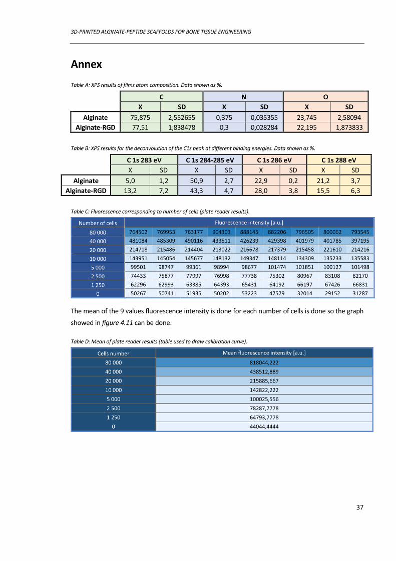
3D-PRINTED ALGINATE-PEPTIDE SCAFFOLDS FOR BONE TISSUE ENGINEERING
37
Annex
Table A: XPS results of films atom composition. Data shown as %.
C N O
X SD X SD X SD
Alginate 75,875 2,552655 0,375 0,035355 23,745 2,58094
Alginate-RGD 77,51 1,838478 0,3 0,028284 22,195 1,873833
Table B: XPS results for the deconvolution of the C1s peak at different binding energies. Data shown as %.
C 1s 283 eV C 1s 284-285 eV C 1s 286 eV C 1s 288 eV
X SD X SD X SD X SD
Alginate 5,0 1,2 50,9 2,7 22,9 0,2 21,2 3,7
Alginate-RGD 13,2 7,2 43,3 4,7 28,0 3,8 15,5 6,3
Table C: Fluorescence corresponding to number of cells (plate reader results).
Number of cells Fluorescence intensity [a.u.]
80 000 764502 769953 763177 904303 888145 882206 796505 800062 793545
40 000 481084 485309 490116 433511 426239 429398 401979 401785 397195
20 000 214718 215486 214404 213022 216678 217379 215458 221610 214216
10 000 143951 145054 145677 148132 149347 148114 134309 135233 135583
5 000 99501 98747 99361 98994 98677 101474 101851 100127 101498
2 500 74433 75877 77997 76998 77738 75302 80967 83108 82170
1 250 62296 62993 63385 64393 65431 64192 66197 67426 66831
0 50267 50741 51935 50202 53223 47579 32014 29152 31287
The mean of the 9 values fluorescence intensity is done for each number of cells is done so the graph
showed in figure 4.11 can be done.
Table D: Mean of plate reader results (table used to draw calibration curve).
Cells number Mean fluorescence intensity [a.u.]
80 000 818044,222
40 000 438512,889
20 000 215885,667
10 000 142822,222
5 000 100025,556
2 500 78287,7778
1 250 64793,7778
0 44044,4444