3D Modelling with Structured Light Gamma Calibration
7
DIGITAL IMAGE PROCESSING AND COMPUTER GRAPHICS VOLUME: 12 | NUMBER: 4 | 2014 | SPECIAL ISSUE 3D Modelling with Structured Light Gamma Calibration Eser SERT 1 , Ibrahim Taner OKUMUS 1 , Deniz TASKIN 2 1 Computer Engineering Department, Engineering and Architecture Faculty, Kahramanmaras Sutcu Imam University, Avsar Kampusu 46100 Kahramanmaras, Turkey 2 Computer Engineering Department, Faculty of Engineering, Trakya University, 22030 Balkan Yerlekesi, Edirne, Turkey [email protected], [email protected], [email protected] Abstract. Structured light method is one of the non- contact measurement methods used for high resolution and high sensitive 3D modeling. In this method, a projector, camera and computer are used. Projector projects patterns that are generated with specific coding strategies onto the object that will be 3D modeled. Cam- era receives these patterns. By processing the images received by the camera, object is 3D modeled. Light intensity that is emitted from the projector generally not a linear function of the signal input. This causes brightness problems in the patterns projected. Thus, images received from the camera needs to the gamma corrected. In this study, gamma calibration method is proposed to overcome this problem. Test results show that proposed calibration system improves the accuracy and quality of the 3D modeling. Keywords 3D modeling, gamma correction, structured light. 1. Introduction With 3D modelling systems, complex surfaced objects can be realistically modelled and be shown on elec- tronic systems with a high sense of reality [1]. Because of these features the need for 3D modelling systems is increasing. One of the 3D modeling systems used in this field is structured light. Using this system, it is possible to produce 3D models of objects with high quality and high sensitivity [2]. A structured light method uses a projector and a camera as seen in Fig. 1. Projector projects specially formed structured light patterns onto the object. Cam- era transfers the pictures of the scene to the computer. Fig. 1: Working principle of structured light modelling system. These scene pictures are processed by the computer and 3D model is obtained [3]. Projected structured light pattern is distorted de- pending on the amount of depth of the object. Distor- tion of the structured light increases with the increase of the depth of the surface [4]. 3D model is obtained by using the distortions in the structured light. In order for to work properly of 3D modeling system, it needs to be calibrated [5], [6]. Calibration steps that are needed to be applied are gamma calibration, cam- era calibration, projector calibration, etc. [7]. Among these, gamma calibration is very important. In this study, a structured light 3D modeling system is de- signed, and gamma calibration method is tested on this system. In the designed system, three phase shifting algorithm is used. This algorithm is chosen because it can provide high quality and high sensitive 3D model- ing compared to other algorithms. c 2014 ADVANCES IN ELECTRICAL AND ELECTRONIC ENGINEERING 347
Transcript of 3D Modelling with Structured Light Gamma Calibration
DIGITAL IMAGE PROCESSING AND COMPUTER GRAPHICS VOLUME: 12 | NUMBER: 4 | 2014 | SPECIAL ISSUE
3D Modelling with Structured Light GammaCalibration
Eser SERT 1, Ibrahim Taner OKUMUS 1, Deniz TASKIN 2
1Computer Engineering Department, Engineering and Architecture Faculty,Kahramanmaras Sutcu Imam University, Avsar Kampusu 46100 Kahramanmaras, Turkey
2Computer Engineering Department, Faculty of Engineering, Trakya University,22030 Balkan Yerlekesi, Edirne, Turkey
[email protected], [email protected], [email protected]
Abstract. Structured light method is one of the non-contact measurement methods used for high resolutionand high sensitive 3D modeling. In this method, aprojector, camera and computer are used. Projectorprojects patterns that are generated with specific codingstrategies onto the object that will be 3D modeled. Cam-era receives these patterns. By processing the imagesreceived by the camera, object is 3D modeled. Lightintensity that is emitted from the projector generallynot a linear function of the signal input. This causesbrightness problems in the patterns projected. Thus,images received from the camera needs to the gammacorrected. In this study, gamma calibration method isproposed to overcome this problem. Test results showthat proposed calibration system improves the accuracyand quality of the 3D modeling.
Keywords
3D modeling, gamma correction, structuredlight.
1. Introduction
With 3D modelling systems, complex surfaced objectscan be realistically modelled and be shown on elec-tronic systems with a high sense of reality [1]. Becauseof these features the need for 3D modelling systemsis increasing. One of the 3D modeling systems usedin this field is structured light. Using this system, itis possible to produce 3D models of objects with highquality and high sensitivity [2].
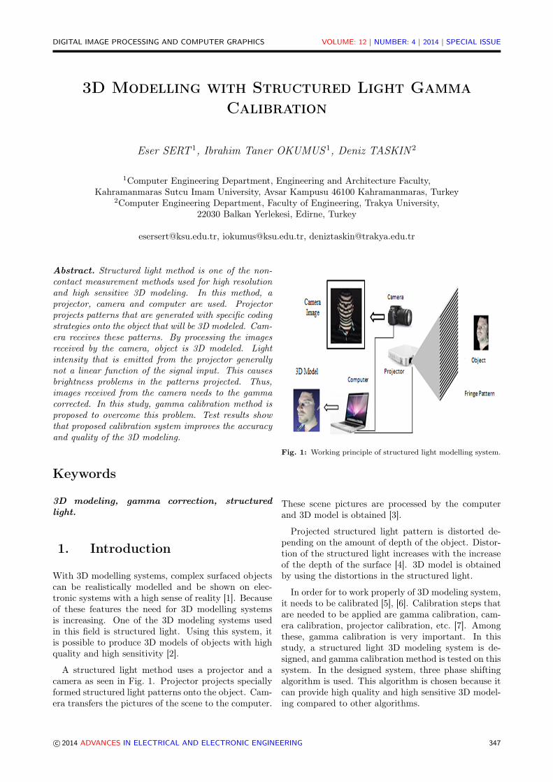
A structured light method uses a projector and acamera as seen in Fig. 1. Projector projects speciallyformed structured light patterns onto the object. Cam-era transfers the pictures of the scene to the computer.
Fig. 1: Working principle of structured light modelling system.
These scene pictures are processed by the computerand 3D model is obtained [3].
Projected structured light pattern is distorted de-pending on the amount of depth of the object. Distor-tion of the structured light increases with the increaseof the depth of the surface [4]. 3D model is obtainedby using the distortions in the structured light.
In order for to work properly of 3D modeling system,it needs to be calibrated [5], [6]. Calibration steps thatare needed to be applied are gamma calibration, cam-era calibration, projector calibration, etc. [7]. Amongthese, gamma calibration is very important. In thisstudy, a structured light 3D modeling system is de-signed, and gamma calibration method is tested on thissystem. In the designed system, three phase shiftingalgorithm is used. This algorithm is chosen because itcan provide high quality and high sensitive 3D model-ing compared to other algorithms.
c© 2014 ADVANCES IN ELECTRICAL AND ELECTRONIC ENGINEERING 347

DIGITAL IMAGE PROCESSING AND COMPUTER GRAPHICS VOLUME: 12 | NUMBER: 4 | 2014 | SPECIAL ISSUE
In the literature, there are various work on gammacalibration. Song Zhang et al. [8] suggested an errorcompensation method for a 3D measurement systemworking on phase shifting method. Study suggeststhat the main source of error is the nonlinearity of thegamma of the image produced by a projector. This er-ror causes problems in sinusoidal signal and 3D model.With the proposed method problems in sinusoidal sig-nals are corrected, problems in fringe images are re-duced, studies performed for another source of errorscaused by projectors gamma.
Li et al. [9] used gamma correction to reduce phaseerrors. Study conducted investigation on gamma-distorted fringe images. Also study investigated phaseerrors, gamma distortion and defocusing-phase errorand defocusing-gamma.
Wang et al. [1] proposed a 4 step application that canbe used in fringe projection profilometry. At the firststep, gamma correction of digital protection is applied.Second step included setting up system components.In the third step, a phase unwrapping is applied. Atthe last step, the system is calibrated by least-squareinverse approach.
In this study by reducing the unnecessary processsteps in the calibration, gamma calibration process isaccelerated. Projection sourced gamma problems arecorrected by calibration process, and an ideal 3D mod-elling is achieved.
Rest of the paper is organized as follows. Section2 describes the working principle of 3D modeling sys-tem. Section 3 discusses Gama Calibration. Section 4contains experimental results and section 5 is the con-cluding remarks.
2. Working Principle of 3DModelling System
Flow diagram of a three-step phase-shifting algorithmis provided in Fig. 2. In the beginning, a calibrationis performed for the system to work properly. Gammacalibration is one the most important one among these.After calibration, projector projects first, second andthird phase patterns onto the object in the given or-der. Step II in Fig. 2 contains three phase patterns.Brightness signal formulations of these phase patternsare given in Eq. (1), Eq. (2), Eq. (3) respectively [10],[11], [12]:
I1(x, y) = I ′(x, y) + I ′′(x, y) cos[Φ(x, y)− 2π/3], (1)
I2(x, y) = I ′(x, y) + I ′′(x, y) cos[Φ(x, y)], (2)
I3(x, y) = I ′(x, y) + I ′′(x, y) cos[Φ(x, y) + 2π/3], (3)
where I ′(x, y) is the average intensity, I ′′(x, y) is in-tensity modulation. I is the intensity value that corre-sponds to x, y coordinates. Figure 3 shows the fringepictures that correspond to sinusoidal signals.
Three different fringe patterns are projected onto theperson to be modeled and these Pictures are taken.Step III in Fig. 2 shows the pictures obtained afterthis process.
Fig. 2: Flow diagram of three-step phase shifting 3D modelingsystem.
Phase matrix is obtained with Eq. (4) by using I1,I2 and I3 intensity values of the phase pictures takenby camera [13], [14], [15]. Phase:
Φ(x, y) = tan−1
( √3(I1 − I3)
2I2 − I2 − I3
). (4)
Wrapped phase matrix is obtained by applying phasewrapping to the phase matrix. The wrapped phasematrix is used to obtain depth matrix. Wrapped phasematrix Picture is shown in step IV of Fig. 2.
c© 2014 ADVANCES IN ELECTRICAL AND ELECTRONIC ENGINEERING 348

DIGITAL IMAGE PROCESSING AND COMPUTER GRAPHICS VOLUME: 12 | NUMBER: 4 | 2014 | SPECIAL ISSUE
Fig. 3: Fringe patterns that correspond to sinusoidal signals.
Unwrap process is applied in step V. This processproduces the depth map that contains the 3D modelinginformation. Figure of the depth map is shown in stepV of Fig 2. At the last step, 3D model is producedusing all the depth maps that are produced in step V.
3. Gamma Calibration
Intensity of light produced by a physical device is nota linear function of the signal fed into the input of thedevice [16], [17]. Examples of this phenomenon can bedistortion of the brightness level of the light producedby a projector. Gamma correction can be formulatedas in Eq. (5), [1]. In the equation, Iin is the signalat the input of the projector, Iout is the signal at theoutput and γ is the gamma level of projector:
IOUT = IγIN . (5)
Images projected by projectors have nonlinear func-tions. γ parameter, which is shown in Eq. (5), of theprojectors has values in the range of 2.2 to 4.6 [1].This causes problems in projecting ideal fringe pat-terns. Thus, gamma calibration becomes a necessity.Gamma correction is performed through Eq. (6):
ImageOut = 255 · (ImageIn/255)(1/γcp), (6)
where ImageIn is the input image, ImageOut isgamma corrected image and γcp is gamma correctionparameter.
Ideal phase patterns of a system that models usingstructured light are shown in Fig. 4. For the analysis,top 5 horizontal strips are turned vertical and inten-sity produces a sinusoidal signal. Brightness analysison each strip of this phase pattern results in a sinu-soidal signal. This is shown in Fig. 4. This sinusoidal
oscillates within the ideal boundaries. Imax is the max-imum Intensity value that Fringe Pattern gets and Iminis the minimum intensity value.
Figure 5(a) shows the brightness curve when thecontrast and brightness level of projector is low. Fig-ure 5(b) shows the case where these levels are high. Asit can be seen from both figures, gamma curve doesnot oscillate within ideal boundaries. Gamma calibra-tion can overcome possible 3D modelling problems bytaking problematic gamma curves into the ideal bound-aries [1], [18].
Figure 6 shows the flow diagram of the designedGamma calibration method. In the beginning, fringepattern is projected onto the scene. In the second step,by analyzing the projected ideal brightness curve andobtained brightness curve is compared. In the fourthstep, the brightness curve is taken to the ideal limitwith appropriate gamma correction parameter. At thelast step, this adjusted fringe pattern is projected.
4. Experimental Results
We performed several tests to see the effects of GammaCalibration on the system. In these tests, by choosingdifferent values of gamma correction parameter shownin step 4 of Fig. 6, resulting effects on 3D modelingperformance are tested.
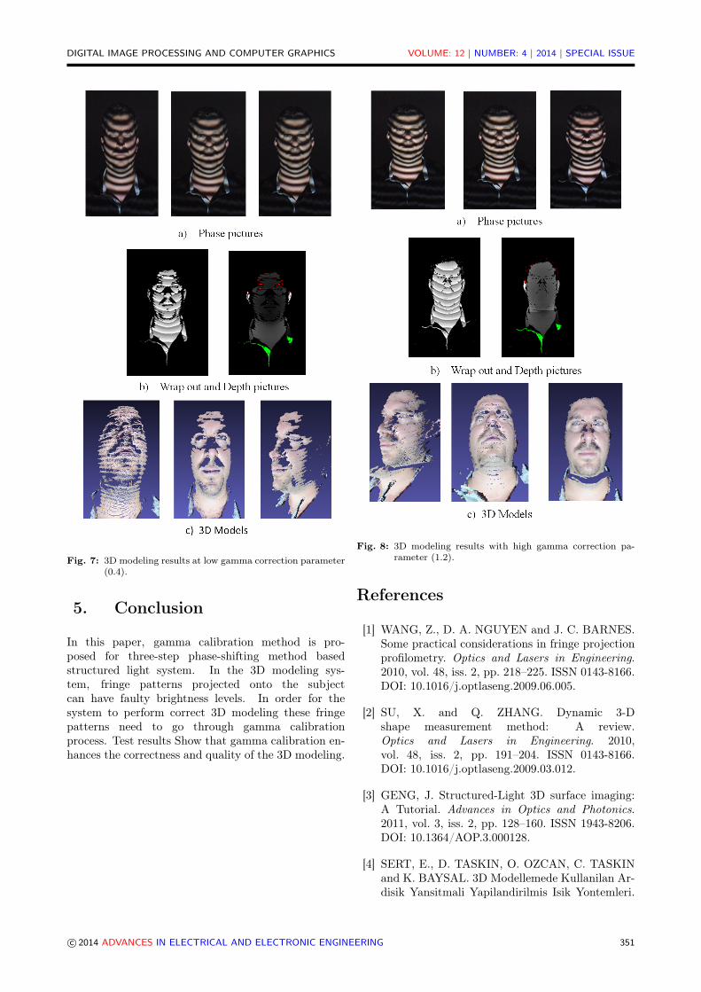
At first 3D modeling is performed with low gammacorrection parameter (0.4). Resulting phase picturesand modeling results are shown in Fig. 7. As it can beseen from Fig. 7(c), number of points that generatesthe 3D model is reduced and ruptures occurred in 3Dmodel.
Fig. 4: Brightness analysis on structured light pattern.
c© 2014 ADVANCES IN ELECTRICAL AND ELECTRONIC ENGINEERING 349

DIGITAL IMAGE PROCESSING AND COMPUTER GRAPHICS VOLUME: 12 | NUMBER: 4 | 2014 | SPECIAL ISSUE
In the second step, 3D modeling is performed withhigh gamma correction parameter (1.2). Resultingphase and modeling pictures are shown in Fig. 8. As itcan be seen from Fig. 8(c) there is a rupture around theneck of the model and this region is also misaligned.
(a) Fringe pattern obtained from low-level contrast andbrightness projector.
(b) Fringe pattern obtained from high-level contrast andbrightness projector.
Fig. 5: Problematic Gamma curves.
In the third step, 3D modeling is performed withideal gamma correction parameter (0.8). Figure 9shows the phase pictures and 3D modeling results forthe ideal gamma correction value. As it can be seenfrom Fig. 9(c) an ideal 3D model is a result in the end.
Fig. 6: Gamma calibration flow diagram.
c© 2014 ADVANCES IN ELECTRICAL AND ELECTRONIC ENGINEERING 350
DIGITAL IMAGE PROCESSING AND COMPUTER GRAPHICS VOLUME: 12 | NUMBER: 4 | 2014 | SPECIAL ISSUE
Fig. 7: 3D modeling results at low gamma correction parameter(0.4).
5. Conclusion
In this paper, gamma calibration method is pro-posed for three-step phase-shifting method basedstructured light system. In the 3D modeling sys-tem, fringe patterns projected onto the subjectcan have faulty brightness levels. In order for thesystem to perform correct 3D modeling these fringepatterns need to go through gamma calibrationprocess. Test results Show that gamma calibration en-hances the correctness and quality of the 3D modeling.
Fig. 8: 3D modeling results with high gamma correction pa-rameter (1.2).
References
[1] WANG, Z., D. A. NGUYEN and J. C. BARNES.Some practical considerations in fringe projectionprofilometry. Optics and Lasers in Engineering.2010, vol. 48, iss. 2, pp. 218–225. ISSN 0143-8166.DOI: 10.1016/j.optlaseng.2009.06.005.
[2] SU, X. and Q. ZHANG. Dynamic 3-Dshape measurement method: A review.Optics and Lasers in Engineering. 2010,vol. 48, iss. 2, pp. 191–204. ISSN 0143-8166.DOI: 10.1016/j.optlaseng.2009.03.012.
[3] GENG, J. Structured-Light 3D surface imaging:A Tutorial. Advances in Optics and Photonics.2011, vol. 3, iss. 2, pp. 128–160. ISSN 1943-8206.DOI: 10.1364/AOP.3.000128.
[4] SERT, E., D. TASKIN, O. OZCAN, C. TASKINand K. BAYSAL. 3D Modellemede Kullanilan Ar-disik Yansitmali Yapilandirilmis Isik Yontemleri.
c© 2014 ADVANCES IN ELECTRICAL AND ELECTRONIC ENGINEERING 351

DIGITAL IMAGE PROCESSING AND COMPUTER GRAPHICS VOLUME: 12 | NUMBER: 4 | 2014 | SPECIAL ISSUE
Fig. 9: 3D modeling results with ideal gamma correction pa-rameter (0.8).
Trakya University Journal of Engineering Sci-ences. 2012, vol. 13, iss. 2, pp. 121–141. ISSN 1305-7766.
[5] ZHANG, Z., C. TOWERS and D. P. TOW-ERS. Compensating Lateral Chromatic Aberra-tion of A Colour Fringe Projection System ForShape Metrology. Optics and Lasers in Engineer-ing. 2010, vol. 48, iss. 2, pp. 159–165. ISSN 0143-8166. DOI: 10.1016/j.optlaseng.2009.04.010.
[6] GORTHI, S. S. and P. RASTOGI. Fringeprojection techniques: Whither we are?Optics and Lasers in Engineering. 2010,vol. 48, iss. 2, pp. 133–140. ISSN 0143-8166.DOI: 10.1016/j.optlaseng.2009.09.001.
[7] MORENO, D. and G. TAUBIN. Simple, Ac-curate, and Robust Projector-Camera Calibra-tion. In: 3D Imaging, Modeling, Process-ing, Visualization and Transmission. Washington:IEEE, 2012, pp. 464–471. ISBN 978-1-4673-4470-8DOI: 10.1109/3DIMPVT.2012.77.
[8] ZHANG, S. and P. S. HUANG. Phase Error Com-pensation For A 3-D Shape Measurement Sys-tem Based On The Phase-Shifting Method. Op-tical Engineering. 2007, vol. 46, iss. 6, pp. 1–9.ISSN 1560-2303. DOI: 10.1117/1.2746814.
[9] LI, Z. and Y. LI. Gamma-Distorted Fringe Im-age Modeling and Accurate Gamma Correction forFast Phase Measuring Profilometry. Optics Let-ters. 2011, vol. 36, iss. 2, pp. 154–156. ISSN 1539-4794. DOI: 10.1364/OL.36.000154.
[10] HUANG, P. S. and S. ZHANG. Fast three-stepphase-shifting algorithm. Applied Optics. 2006,vol. 45, iss. 21, pp. 5086–5091. ISSN 2155-3165.DOI: 10.1364/AO.45.005086.
[11] ZHANG, S. and S.-T. YAU. High-Speed Three-Dimensional Shape Measurement System Us-ing A Modified Two-Plus-One Phase-ShiftingAlgorithm. Optical Engineering. 2007, vol. 46,iss. 11, pp. 113603–113611. ISSN 1560-2303.DOI: 10.1117/1.2802546.
[12] ZHANG, Z., G. NEJAT, H. GUO and P. HUANG.A Novel 3D Sensory System For Robot-AssistedMapping of Cluttered Urban Search and Res-cue Environments. Inteligent Service Robotics.2011, vol. 4, iss. 2, pp. 119–134. ISSN 1861-2784.DOI: 10.1007/s11370-010-0082-3.
[13] KARPINSKY, N. and S. ZHANG. High-Resolution, Real-Time 3D Imaging With FringeAnalysis. Journal of Real-Time Image Processing.2012, vol. 7, iss. 1, pp. 55–66. ISSN 1861-8219.DOI: 10.1007/s11554-010-0167-4.
[14] ZHANG, S. Recent Progresses on Real-Time 3DShape Measurement Using Digital Fringe Projec-tion Techniques. Optics and Lasers in Engineer-ing. 2010, vol. 48, iss. 2, pp. 149–158. ISSN 0143-8166. DOI: 10.1016/j.optlaseng.2009.03.008.
[15] ZHANG, S. and P. S. HUANG. Novel Method forStructured Light System Calibration. Optical En-gineering. 2006, vol. 45, iss. 8, pp. 1–8. ISSN 1560-2303. DOI: 10.1117/1.2336196.
[16] POYNTON CH. Frequently Asked Questionsabout Gamma. 2014. Available at: http://www.poynton.com/PDFs/GammaFAQ.pdf.
[17] WADDINGTON, C. and J. KOFMAN. Analy-sis Of Measurement Sensitivity To IlluminanceAnd Fringe-Pattern Gray Levels For Fringe-Pattern Projection Adaptive To Ambient Light-ing. Optics and Lasers in Engineering. 2010,vol. 48, iss. 2, pp. 251–256. ISSN 0143-8166.DOI: 10.1016/j.optlaseng.2009.07.001.
c© 2014 ADVANCES IN ELECTRICAL AND ELECTRONIC ENGINEERING 352

DIGITAL IMAGE PROCESSING AND COMPUTER GRAPHICS VOLUME: 12 | NUMBER: 4 | 2014 | SPECIAL ISSUE
[18] MARTINEZA, A., J. A. RAYASA, H. J. PU-GAB and K. GENOVESE. Iterative estimation ofthe topography measurement by fringe-projectionmethod with divergent illumination by consider-ing the pitch variation along the x and z direc-tions. Optics and Lasers in Engineering. 2010,vol. 48, iss. 9, pp. 877–881. ISSN 0143-8166.DOI: 10.1016/j.optlaseng.2010.04.002.
About Authors
Eser SERT received the M.Sc. degree in 2010,and the Ph.D. degree in 2013, all in ComputerEngineering at Trakya Univesity, Turkey. Currentlyhe is Assistant Professor at Computer Engineer-ing of Kahramanmaras Sutcu Imam University.His research interests include 3D modeling system,
image processing, computer vision, field programmablegate arrays (FPGA)and artificial intelligence.
Ibrahim Taner OKUMUS was born in Kahra-manmaras, Turkey. He received his M.Sc. and Ph.D.degrees from Sysracuse University, USA. He is cur-rently working as an Associate Professor at ComputerEngineering Department of Kahramanmaras SutcuImam University, Turkey. His research interestsinclude wireless networks, software defined networks,wireless sensor networks and computer networks ingeneral.
Deniz TASKIN received the M.Sc. degree in2004, and the Ph.D. degree in 2007, all in ComputerEngineering at Trakya Univesity, Turkey. Currentlyhe is Assistant Professor at Computer Engineering ofTrakya University.
c© 2014 ADVANCES IN ELECTRICAL AND ELECTRONIC ENGINEERING 353