3D Detailing of Reinforced Concrete and Steel Connections With AutoCAD Revit Structure2
16
SE327-2: 3D Detailing of Reinforced Concrete and Steel Connections with AutoCAD® Revit® Structure Damien Legrand – BIM Solutions Centre Ltd SE327-2 Learn about the benefits of using Revit Structure 3D rebars and structural connections for your detail documentation. Based on real project scenarios, this presentation will examine in-depth the techniques and mechanisms of detailing in Revit Structure. This includes creating structural connection library parts, working with 3D reinforcement, developing a custom tagging library, and managing and optimizing the detail processes using the Revit database and interface. We will closely observe the efficiency and validity of these methods in a project environment. Become skilled at improving the integrity and the consistency of the detailing phase and reducing the risk of errors. About the Speaker: Damien is a BIM Business development consultant and owner of BIM Solutions Centre Ltd. in Wellington, New Zealand. He graduated (MEng) and worked as a bridge engineer in France and Ireland before moving to the ANZ region. He has now specialized in BIM technology for the last six years and provided consulting services for a great range of industry professionals (architect, engineers and contractors). [email protected]
Transcript of 3D Detailing of Reinforced Concrete and Steel Connections With AutoCAD Revit Structure2

SE327-2: 3D Detailing of Reinforced Concrete and Steel Connections with AutoCAD® Revit® Structure
Damien Legrand – BIM Solutions Centre Ltd
SE327-2 Learn about the benefits of using Revit Structure 3D rebars and structural connections for
your detail documentation. Based on real project scenarios, this presentation will examine in-depth the
techniques and mechanisms of detailing in Revit Structure. This includes creating structural connection
library parts, working with 3D reinforcement, developing a custom tagging library, and managing and
optimizing the detail processes using the Revit database and interface. We will closely observe the
efficiency and validity of these methods in a project environment. Become skilled at improving the
integrity and the consistency of the detailing phase and reducing the risk of errors.
About the Speaker: Damien is a BIM Business development consultant and owner of BIM Solutions Centre Ltd. in Wellington,
New Zealand. He graduated (MEng) and worked as a bridge engineer in France and Ireland before
moving to the ANZ region. He has now specialized in BIM technology for the last six years and provided
consulting services for a great range of industry professionals (architect, engineers and contractors).
3D Detailing of Reinforced Concrete and Steel Connections with AutoCAD® Revit® Structure
2
Introduction
Detailing is always a challenging part of the documentation process. This presentation will focus on detailing during the design phase. Typically the details you can find on a “For tender / For Construction” set of documentation. Revit Structure seems best suited for these type of details as it follows the development of a 3d model of the structure and the production of design documentation.
As detailing is a full task of its own, I usually compare it to a job a tradesman will complete onsite with all the constraints and expectation that come with it:
So the same way we’ll expect a good plumber to do his job, what are we entitled to expect from a good detailer?
• Someone that will recommend the more appropriate detailing method
• Someone that will do a professional job in a reasonable timeframe, including a good preparation and finish
• Someone that will be able to maintain the detail after the job has been completed
The presentation will go through the methods and techniques of detailing steel connections and reinforced concrete elements
About the formatting in this document
Technical Tips : italic with a light blue background
Based on my own experience and my discussions with other users, they are good practice techniques I use frequently.
Revit specific terminology: underlined
They refer to a Revit Command or a Setting
Keywords: bolded
They represent a key concept and/or phase of the detailing process
Problematic around detailing
It is important to get a good description of the reasons we are going to spend time on a steel connection or a reinforced concrete detail. This will determine the level of details required and justify the use or not of 3d components for creating the detail.
Doing a detail in 3d does not take more time than doing it in 2d, however it may prove very time consuming to rework the same detail over and over for various reasons.
Experience shows that engineers want to see finished details quite early in the design process. Lets try to understand the impact on the approach the Revit operator can choose to perform the detailing task.
• If the detail intended is “standard” (general description of the detail solution without checking the workability), the benefit of 3d is limited
• If the detail intended is “for construction” (validating the workability of the solution and giving enough information to prepare a shop drawing and fabricate), 3d detailing can prove to be very efficient.
The main benefit in detailing in 3d is the confidence that your design intended as particular steel connection or a reinforced concrete element is working and applicable.
Secondary benefits are the consistency, accuracy and the control ability you can have over your detail information. Generally at the project scale a 3d detail is a lot easier to manage than an assembly of 2d lines.
Tip: Compare the number of instances (lines + text) required to produce a 2d representation of a detail with the number of 3d components to achieve the same result

3D Detailing of Reinforced Concrete and Steel Connections with AutoCAD® Revit® Structure
3
Detailing of steel connections
Prerequisite / Requirements
• Model quality and accuracy
In order to detail efficiently, the model containing the structural steel members needs to be spatially accurate. This sometimes goes against the automatic placing and trimming feature of Revit.
Example of required accuracy in the modeling of cross bracing and girts
A lack of accuracy in the placing of the structural steel member will result in problems in using the dimension or align command, placing face based components and controlling the visual display of the detail.
• Quality of structural steel families
It is important to have consistency in the families used to model the steel members. Steel families need to offer an easy control of the end member and should allow the use of the opening by face in both vertical and horizontal faces. The cross section rotation parameter is not user friendly and changes the position of the member axis when the angle value is changed.
Tip: It may pay off to rebuild your structural steel families with a user defined angle parameter.
It is important to be able to control the section angle without moving the member axis
Tip: Constrain the nested detail component to both horizontal and vertical reference planes
Preparation
• Display (views, filter, object style, view template, special parameters)
The first step in preparing your steel detail is to create a good working environment.
The creation of multiple views to visualise and navigate the detail zone will speed up the detail process significantly. A good combination is a parallel, orthogonal section or callout and a 3d view of the detail zone.

3D Detailing of Reinforced Concrete and Steel Connections with AutoCAD® Revit® Structure
4
3d snap shot of the detail
Parallel detail view
Orthogonal detail view
Tip Create your detail section/callout first and use the steering wheel to orient the 3d view to your detail section. This will crop automatically around the detail zone
The use of view template is a quick way to set visual display in the detail views. This includes the scale, visibility/graphics, filters, transparency, level of details, visual style
Tip: Only turn on what need to be seen in the detail view from the visibility/graphics dialog
Filters are an easy way to control the display of connections elements and assembly
• Browser organization and view names
Creating different detail view types and using a good view naming convention will facilitate managing your detailing work in general.
Detail View types Browser Organisation Detail View Naming Convention
• Library of structural connections
The library of structural connections is what the tool box is to the tradesman, and any tradesman would say you need the right tools to do a good job. It is recommended to set create a “project library” folder on the server where you will save and name your structural connection families accordingly to your project naming convention. The library can be divided into two sections
o Cleat, plates
Due the large number of plate and cleat shapes, it is nearly impossible to generate an exhaustive library. However assuming that a minimum amount of time will be spent finalizing the geometry of the plate according to the detail conditions, these 3 plates templates can generally suffice

3D Detailing of Reinforced Concrete and Steel Connections with AutoCAD® Revit® Structure
5
Side rect plate
Face rect plate
L plate
Using one of these templates as a starting point will help maintaining some consistency in the plates naming convention and the parameters in use (thickness, material)
Tip: You can generate create a catalogue file template to store a wide range of thicknesses, and then it is a matter of copying your catalogue file and renaming it to access all the family types corresponding to the different thicknesses.
o Fastening components, bolts, rivets
Assuming the level of detail required does not require seeing in detail the geometry of the bolts, we can use a highly parametric bolt family, to create all the required bolt assemblies
Single Bolt
2 bolts
4 bolts linear
4 bolts square
A simple math exercise shows that the combination of plate + fastening component is nearly infinite, so combining them in a single Revit family is going to create a very large number of library parts and can become heavy to manage.
Tip: When placing a face based component (bolt) on top of another face based component (plate), Revit creates automatically a hosting constraint between the two. This mean if you move the first component, the second one will follow.
• Library of annotations
o Tags
The difficulty in setting up the library of tags to accompany your structural connections families is essentially in the formatting conditions (Overall width of the text block and text alignment)The tag family can contain a combination of 3 labels with 3 different alignment settings (left, centre, right) and 3 types matching the different justification situation
The information shown in the tag can be linked to the “comment” parameter, offering a good compromise in the ability to schedule it and flexibility in inputting the information.
3D Detailing of Reinforced Concrete and Steel Connections with AutoCAD® Revit® Structure
6
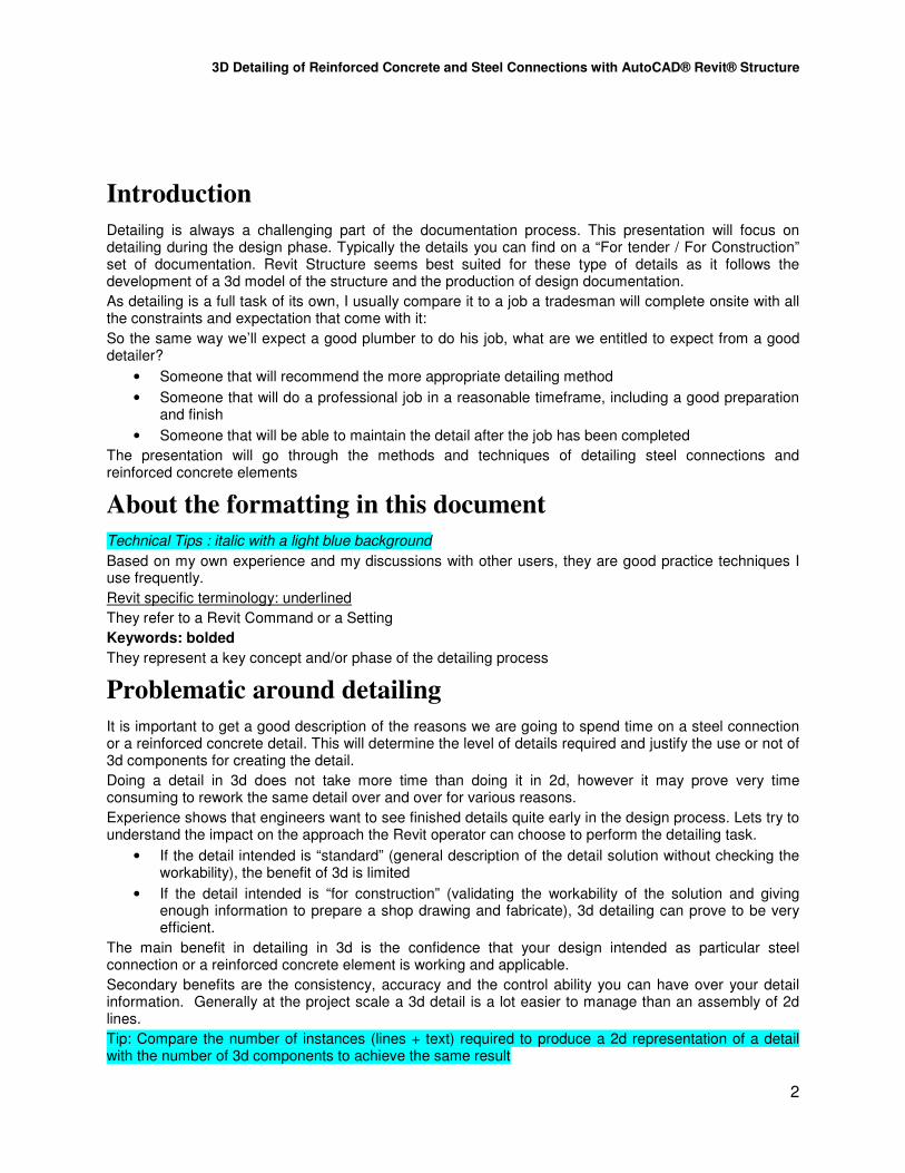
o Symbols
There is still information that is not worth using 3d components for (welding, break line),annotation symbols are very efficient to represent such information.
Execution
• Adjusting, trimming, copying the steel members’ ends
start / end extension properties cut geometry opening by face
• Creating and Saving the connection components
The final plate component can be created based on the appropriate plate template, after editing the family, completing the plate family (adding slotted holes, reshaping for non-standard shapes), saving and naming the plate family accordingly to your project naming convention (P1, P2, C1)
P1.rfa
Starting with the Plate – Face template
Adding the slotted holes Saving and Naming the new made plate
• Load the plate and the bolt assembly family
Tip: You can drag and drop from windows explorer
• Creation of the connection assembly / placing structural connections
Tip: Setup a key board short cut to place a component (eg 77)
The structural connection components are placed in the model, using the different views created to get the best access point.
• Annotating
Tags are dropped around the structural connection elements
Tip: use the free endoption for the leader as it is more flexible to place your tag on the detail.
Tip: text can be entered after clicking on the blue question mark of the tag.
To help with the formatting issue, additional shared parameters (e.g. “Extra Comment 1”, “Extra Comment 2”) can be used to store and display more information. There is no need to insert these in all the families individually, they can be declared as project parameters but need to be shared with the tag families.

3D Detailing of Reinforced Concrete and Steel Connections with AutoCAD® Revit® Structure
7
Detail Finishes
The view template should take care of most of the display settings, additional linework may be required to finalise the details
Symbols and detail component can be added to complete the detail representation
Weld Symbol Break Line Symbol nested in Detail Component Grid Detail Component
Detail Maintenance
The most challenging part of detailing is to manage the life cycle of your detail information while the project carries on and modification/changes occur.
Changes can be categorised into 3 grades
• Low Impact changes: often the results of minor revision of the design (change of member size, change of position of a member), they are relatively easy to integrate and need a minimum amount of rework on the detail
• Medium Impact changes, often driven by external reasons to the design (change in the type of member UC to RHS due to supply consideration)
• High Impact changes, could be client and or architectural driven and result in having to completely redo the detail from scratch.
The face based constraint prevent the plate from disconnecting from the main member, however it can only maintain the relationship with one face, which means in the situation of an L plate, only one face is covered. It also creates an error message if the relationship between the plate and the member is to be lost.
Locking the connection components to the member (aligning the plate to the end of a steel framing object) can be useful in the situation of low impact changes
Generally it is good to remember that a change of design creates a significant amount of work to readjust the details (2D and 3D), which reinforces the importance of assessing the advancement of the design and communicating with the designer or engineer.

3D Detailing of Reinforced Concrete and Steel Connections with AutoCAD® Revit® Structure
8
Examples
Technology Block Building – College Project
Fire station

3D Detailing of Reinforced Concrete and Steel Connections with AutoCAD® Revit® Structure
9
Service Ladder – Reservoir Tank
3D Detailing of Reinforced Concrete and Steel Connections with AutoCAD® Revit® Structure
10
Detailing of reinforced concrete
Requirement
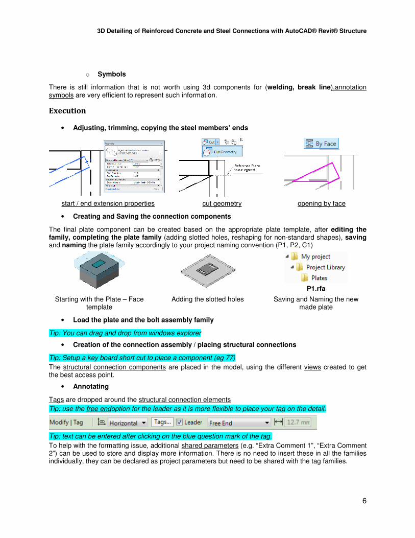
• Model quality and accuracy
When considering detailing in 3d the reinforcement, it is important to make sure that the geometry of the 3d concrete model is accurate (at least around the detail zone). This means all recesses, steps, variation of thickness, slopes need to be modelled. Adjacent concrete elements should be joined (Join Geometry) if applicable
• Quality of reinforced concrete families
All potential rebars hosts(structural framing, structural column, structural foundations) must have their material type set to “concrete”.
Wall structural usage need to be set to Load bearing / Shear / Structural
Combined
The Structural thick Box need to be on for the floors
User defined families must have their material type parameter set to
Concrete
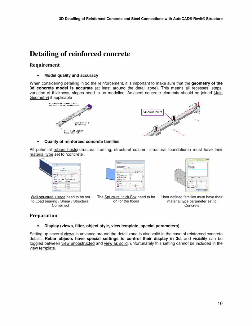
Preparation
• Display (views, filter, object style, view template, special parameters)
Setting up several views in advance around the detail zone is also valid in the case of reinforced concrete details. Rebar objects have special settings to control their display in 3d, and visibility can be toggled between view unobstructed and view as solid, unfortunately this setting cannot be included in the view template.

3D Detailing of Reinforced Concrete and Steel Connections with AutoCAD® Revit® Structure
11
Refer to the section: Display (views, filter, object style, view template, special parameters) of the Steel connections detail chapter for all other display settings.
• Browser organization and view names
Refer to the section: Browser organization and view names of Steel Connections detail chapter
• Library of Rebars and Rebar settings
Because rebar families are systems families, the exercise of creating all the required bar types and sizes needs to take place in the main model file (this can be standardised in the company template). This also includes creating the hook types.
When inserting a rebar into the model, Revit automatically associates a rebar shape to the rebar element. When sketching a bar with no matching rebar shape loaded in your project file Revit will create a new rebar shape and name it automatically rebar shape 1 ( incrementing).
Tip: From experience there is no need to spend a lot of time developing complex rebar shape in advance.
Cover settings can be defined separately and assigned to all reinforced concrete elements.

3D Detailing of Reinforced Concrete and Steel Connections with AutoCAD® Revit® Structure
12
• Library of Rebar Annotations
The rebar tags are essential in making the 3d concrete detailing process worthwhile. Annotations associated to concrete details are difficult to standardise (e.g. Bar size – distribution – bonding condition – additional info for grade). Rebar tags are usually the result of a combination of labels referring to different parameters of the rebar elements.
Formatting can be tedious: different type can be created to allow different alignments
Execution
• Placing Rebars
An efficient way to place rebar in the model is to first select the concrete host and start from the Modify selected element ribbon. Toggling between the views specially created for the detail will ensure a quick and accurate placement of the rebar element.
Depending on the complexity of the bar, you can choose the rebar shape in the drop list or use the sketch option. The bar will automatically size itself based on the host geometry and the cover settings. However this does not mean it provides a great result all the time. Rebars are usually running through several elements, ensuring the connection. To set the final dimensions of the rebar, the property dialog will let you access and edit the length of any segment of the bar
Once you have the rebar placed accurately, the distribution condition (layout) can be entered
Tip: Use the space bar to rotate your shape before inserting it
Tip: Manipulating the Shape parameter is an easy way to size your bar accurately
Tip: Check in your 3d views the start and finish of your bar distribution and adjust with the shape handle.
Tip: It is faster to use a regular shape and edit the sketch afterwards
When using area reinforcement and path reinforcement in your slabs and walls, it will need to be integrated in the detail. The limitation is when you want the slab or wall reinforcement to act as a starter bar in a foundation or beam. Extremities of area reinforcement are difficult to control without compromising the display in plan views.
Revit Extensions are worth considering, as they automate the placement of rebars, However like any automated methods it has its limitations, amongst them are the non-use of distribution layout and the

3D Detailing of Reinforced Concrete and Steel Connections with AutoCAD® Revit® Structure
13
problem with the clearance between the main bars and the ties or stirrups. More details at http://usa.autodesk.com/adsk/servlet/item?siteID=123112&id=15281259
• Annotating
Dropping tags on the detail view is pretty straight forward. The comments parameter is used to add all extra information needed to be displayed in the tag. Extra parameters can be created to display additional information (ex Leg)
Bar Type – Spacing Tag # - Bar Type tag Area Reinforcemernt Tag
Tip: create a shortcut for the tag command “TG” and place the default tag, then select from the drop list the tag required for the rebar selected.
• Final display touch
Tip medium level of detail will show single line reinforcement while fine detail will show double line
There are different visual settings used to represent the reinforcement. In case you need to show the reinforcement in the background dashed, there is still the need of overwriting the display by element. However you can trust that the position of all the rebar you seen in your detail is correct which will help you validate the workability of your detail.
There is no easy way I know to model the hard fill and membrane (DPM) to go around the concrete foundation, and this needs to be done in 2d using filled regions.
Membrane as Detail Line
Sand Blinding and Hardfill as Filled Region
Break Line as Symbol nested in Detail Component
Notes as Detail Component Tag (type mark parameter)
Maintenance
Preventing the detail to blow out when the concrete elements are changing or moving can be pretty tricky and proves to be more difficult than for a steel connection. The main reason being a change of position or geometry in a concrete element results in a different bar layout in the detail
The key is to be consistent in chasing the consequences of a model change amongst your details. Your browser organisation and a good naming convention can proved to be very useful in this case.
Once again the timing issue is critical and it can pay off to hold until you can accurately estimate what design information you can base your detail on

3D Detailing of Reinforced Concrete and Steel Connections with AutoCAD® Revit® Structure
14
Example
Women’s Prison

3D Detailing of Reinforced Concrete and Steel Connections with AutoCAD® Revit® Structure
15
Hollowcore Bridge Project
High Security Prison Project

3D Detailing of Reinforced Concrete and Steel Connections with AutoCAD® Revit® Structure
16
Summary / Evaluation
Criteria Comments 3D 2D
Speed The key to a good speed in your 3d detailing tasks is a good preparation, a good template to take care of the display settings and a complete and organised library
3/5 3/5
Accuracy Definitely a step up from 2D, the 3D environment lets you check the impact of your detail work in all directions
4/5 3/5
Flexibility A 3D detail is flexible in the sense of you only need to modify a small number of elements to adjust or update your detail
3/5 1/5
Integrity Using tags to display the detail information on detail views, guarantee the integrity of the detail
5/5 2/5
Workability This is the main benefit of using 3D, you can validate instantly the workability of your detail solution.
4/5 2/5
Durability Probably the weakest part of the process, it still is difficult to maintain the integrity of the detail as design changes occurs
2/5 2/5
Conclusion
It is true that 3D detailing is enhancing the quality of the project deliverable. The technicality of 3D detailing is by far not the biggest hurdle you face, patience and consistent / rigorous approach are the keys to a successful implementation of the 3D detailing techniques.
The main challenge is managing the time spent detailing. 2D or 3D it can prove to be extremely time consuming to rework a detail over and over. It is important to time your detailing work with the general advancement of the project, and coordinate your efforts with the rest of design team.
Tip: It generally pays off to wait a few days and when your are discussing a detail concept with an engineer, it is also good practice to do your coordination with the architectural information before diving into detailing.