3D CFD modelling of solid biomass combustion in grate · PDF file3D CFD modelling of solid...
22
3D CFD modelling of solid biomass combustion in grate furnaces Ramin Mehrabian Robert Scharler, Ingwald Obernberger IEA Bioenergy Task 32: Biomass Combustion and Cofiring Copenhagen, June 2013
Transcript of 3D CFD modelling of solid biomass combustion in grate · PDF file3D CFD modelling of solid...
3D CFD modelling of solid biomass combustion in grate furnaces
Ramin Mehrabian Robert Scharler, Ingwald Obernberger
IEA Bioenergy Task 32: Biomass Combustion and Cofiring Copenhagen, June 2013
2
Contents
■ Scope of work ■ Methodology ■ Model overview
■ Thermal conversion of solid biomass in packed beds ■ Hydrodynamics of a packed bed
■ Results ■ Particle motion on the grate ■ Thermal conversion of particles and particle temperature ■ Gas phase temperature and species concentrations
at the bed surface ■ Summary and conclusions ■ Outlook
3
Scope of work
■ Development of a CFD based model for packed bed combustion in biomass grate furnaces
■ A model for the thermal conversion of the packed bed should include models for
■ the particle movements in the fuel bed ■ the thermal conversion of the particles
■ Link of the packed bed model and link with an in-house developed CFD model for the turbulent reactive flow in the combustion chamber
■ Application and test of the model with a 20 kW underfeed stoker grate furnace and a pilot-scale moving grate furnace (180 kW)
4
Methodology
Modelling of the thermal conversion of packed beds can be divided into two parts:
1. Thermal conversion of particles ■ A layer model, implemented as UDF in ANSYS FLUENT, has been
developed to consider the biomass particles as thermally thick particles with intra-particle gradients.
2. Hydrodynamics of packed beds ■ The Euler-Granular model of ANSYS FLUENT is used, since it allows to
consider particle-particle collisions. ■ The Euler-Granular model does not enable to hook the layer model. ■ The velocity field of the particle phase from the Euler-Granular simulation
without chemical reactions is saved and is then used in the subsequent simulation of particle combustion with the Discrete Phase Model.
5
Thermal conversion of particles (layer model) (I)
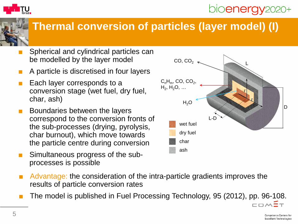
■ Spherical and cylindrical particles can be modelled by the layer model
■ A particle is discretised in four layers ■ Each layer corresponds to a
conversion stage (wet fuel, dry fuel, char, ash)
■ Boundaries between the layers correspond to the conversion fronts of the sub-processes (drying, pyrolysis, char burnout), which move towards the particle centre during conversion
■ Simultaneous progress of the sub-processes is possible
wet fuel
dry fuel char ash
D
L
H2O
CnHm, CO, CO2, H2, H2O, …
CO, CO2
r
r
L-D
■ Advantage: the consideration of the intra-particle gradients improves the results of particle conversion rates
■ The model is published in Fuel Processing Technology, 95 (2012), pp. 96-108.
6
Thermal conversion of particles (layer model) (II)
■ Drying is assumed to take place at a constant temperature (the boiling temperature of water). Therefore, the drying rate is limited by the heat transfer.
■ Pyrolysis is described by three independent competitive reactions for cellulose, hemicellulose, and lignin.
■ The kinetic rate of each reaction is calculated by an Arrhenius equation.
■ The empirical constants are obtained from fuel specific fast heating rate TGA experiments.
■ Char oxidation and gasification reactions are assumed to be limited by the mass transport rate.
■ CO and CO2 are the products of char oxidation. ■ Char gasification with H2O, CO2 and H2 is also considered.
7
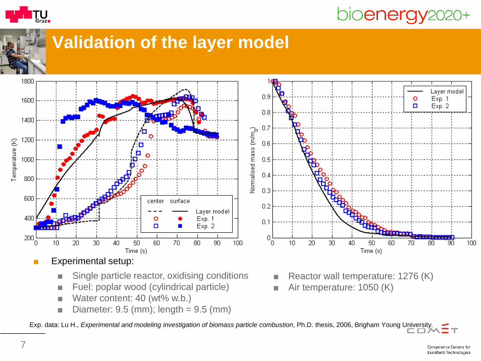
Validation of the layer model
Exp. data: Lu H., Experimental and modeling investigation of biomass particle combustion, Ph.D. thesis, 2006, Brigham Young University.
■ Reactor wall temperature: 1276 (K) ■ Air temperature: 1050 (K)
■ Experimental setup: ■ Single particle reactor, oxidising conditions ■ Fuel: poplar wood (cylindrical particle) ■ Water content: 40 (wt% w.b.) ■ Diameter: 9.5 (mm); length = 9.5 (mm)
8
Hydrodynamics of the packed bed
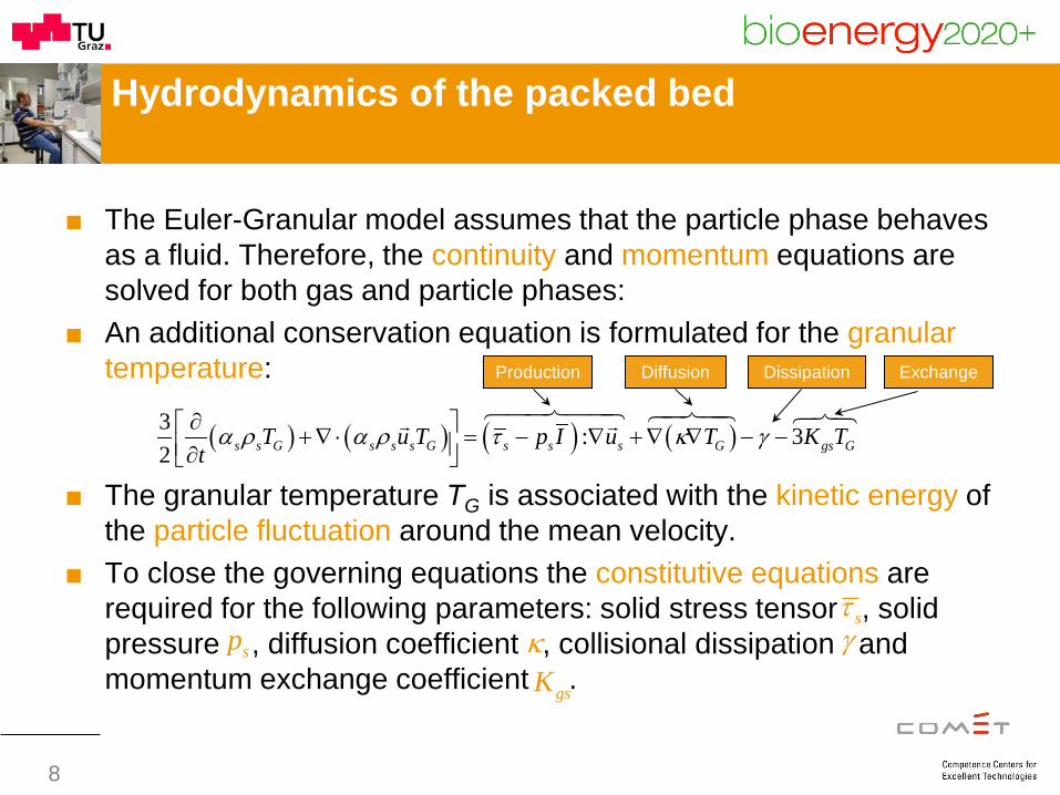
■ The Euler-Granular model assumes that the particle phase behaves as a fluid. Therefore, the continuity and momentum equations are solved for both gas and particle phases:
■ An additional conservation equation is formulated for the granular temperature:
■ The granular temperature TG is associated with the kinetic energy of the particle fluctuation around the mean velocity.
■ To close the governing equations the constitutive equations are required for the following parameters: solid stress tensor , solid pressure , diffusion coefficient , collisional dissipation and momentum exchange coefficient .
( ) ( ) ( ) ( )3 : 32 s s G s s s G s s s G gs GT u T p I u T K T
tα ρ α ρ τ κ γ∂ +∇ ⋅ = − ∇ +∇ ∇ − − ∂
Production Diffusion Dissipation Exchange
sτsp κ γ
gsK
9
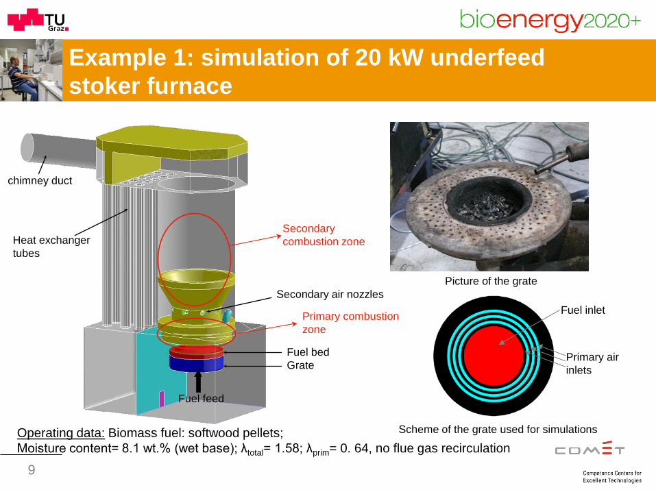
Example 1: simulation of 20 kW underfeed stoker furnace
Scheme of the grate used for simulations
Fuel inlet
Primary air inlets
Picture of the grate
Grate Fuel bed
chimney duct
Heat exchanger tubes
Secondary air nozzles
Fuel feed
Primary combustion zone
Secondary combustion zone
Operating data: Biomass fuel: softwood pellets; Moisture content= 8.1 wt.% (wet base); λtotal= 1.58; λprim= 0. 64, no flue gas recirculation
10
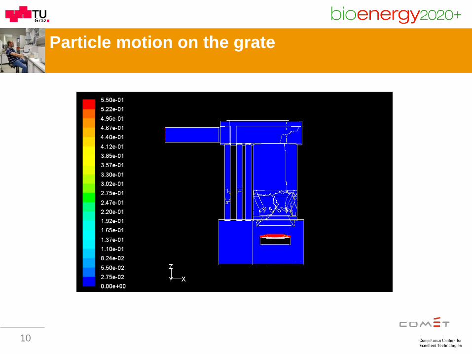
Particle motion on the grate
11
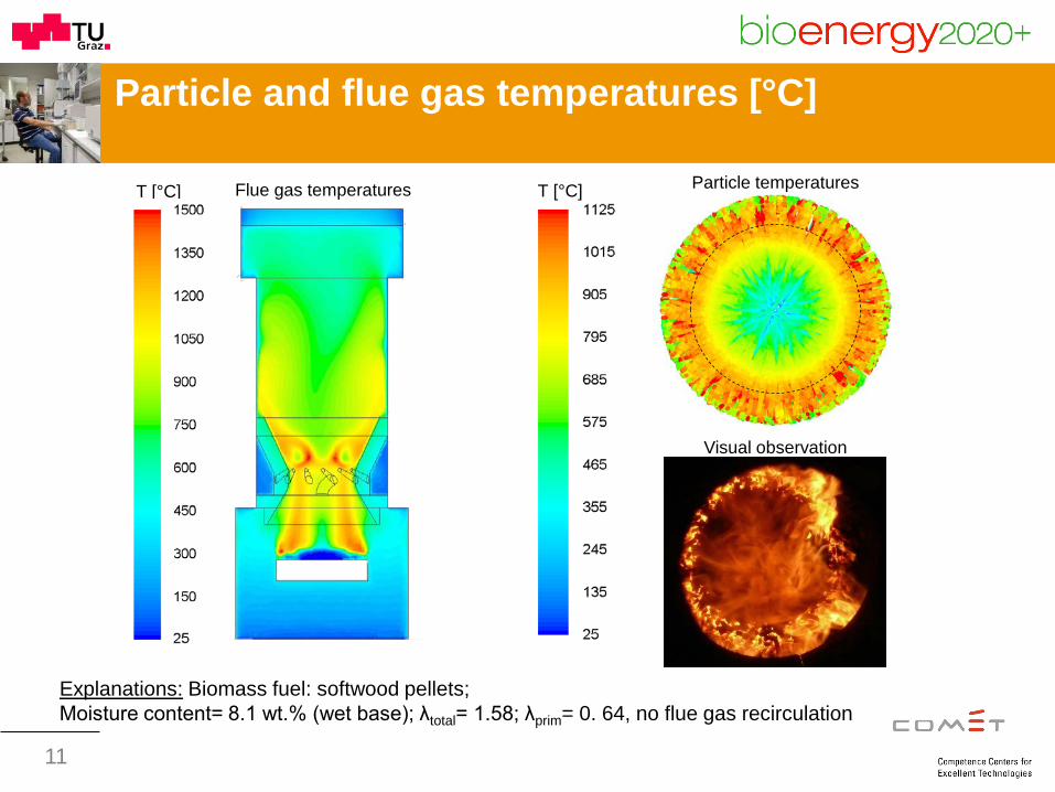
Particle and flue gas temperatures [°C]
Explanations: Biomass fuel: softwood pellets; Moisture content= 8.1 wt.% (wet base); λtotal= 1.58; λprim= 0. 64, no flue gas recirculation
Flue gas temperatures T [°C] Particle temperatures
Visual observation
T [°C]
12
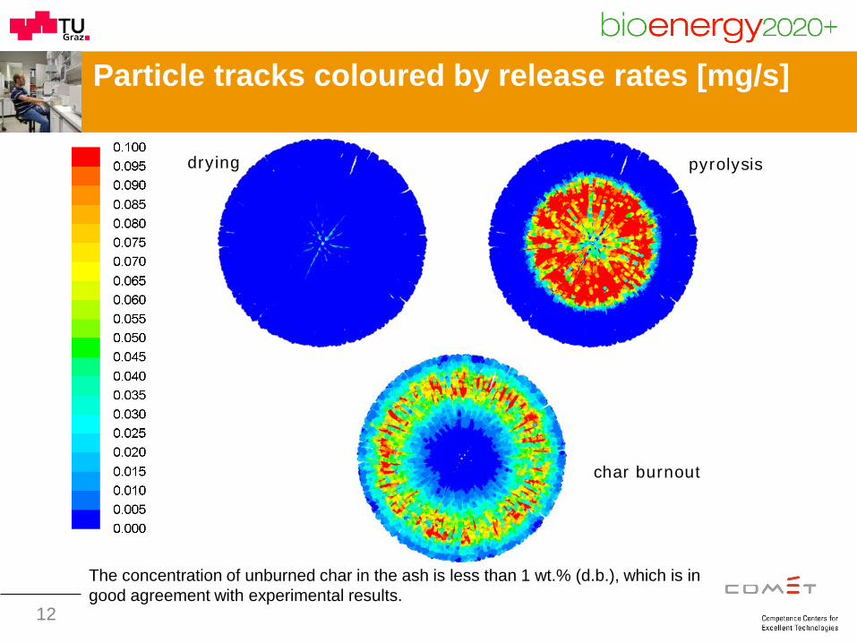
Particle tracks coloured by release rates [mg/s]
drying
char burnout
pyrolysis
The concentration of unburned char in the ash is less than 1 wt.% (d.b.), which is in good agreement with experimental results.
13
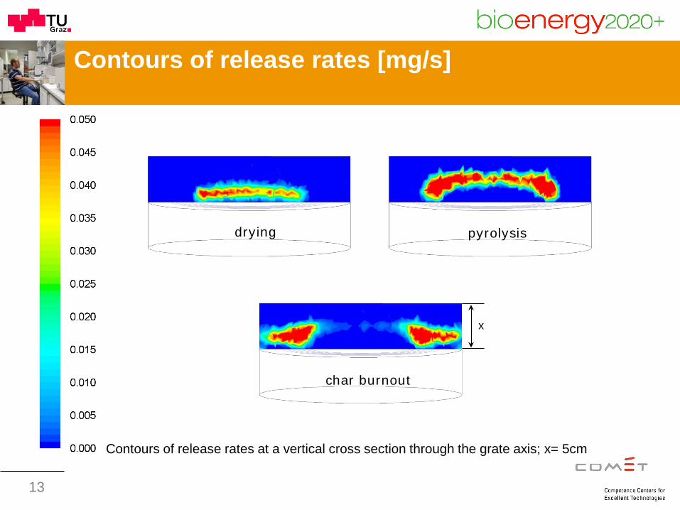
drying
char burnout
pyrolysis
Contours of release rates [mg/s]
Contours of release rates at a vertical cross section through the grate axis; x= 5cm
x
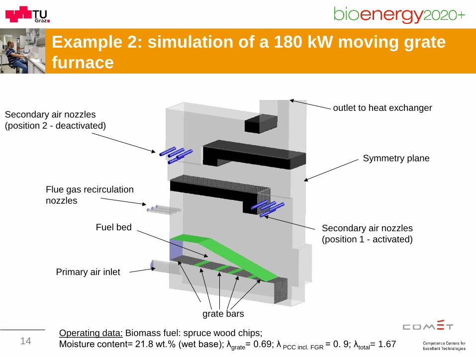
Example 2: simulation of a 180 kW moving grate furnace
Primary air inlet
Flue gas recirculation nozzles
Secondary air nozzles (position 1 - activated)
outlet to heat exchanger
grate bars
Fuel bed
Symmetry plane
14 Operating data: Biomass fuel: spruce wood chips; Moisture content= 21.8 wt.% (wet base); λgrate= 0.69; λ PCC incl. FGR = 0. 9; λtotal= 1.67
Secondary air nozzles (position 2 - deactivated)
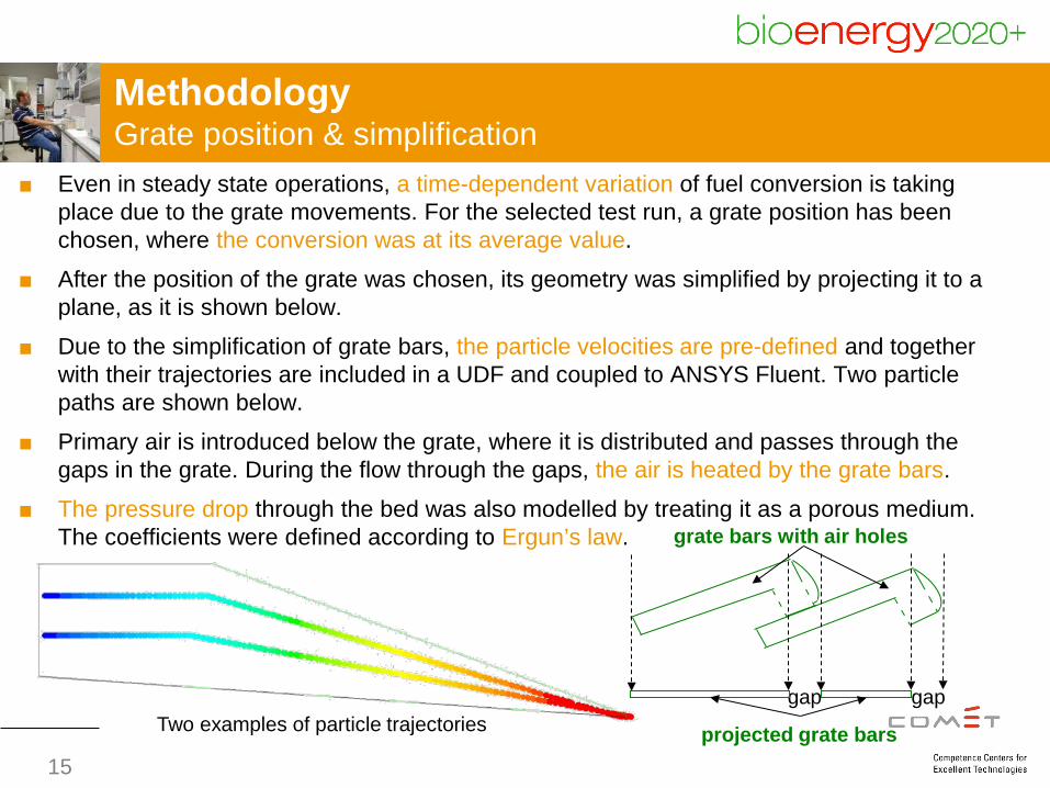
Methodology Grate position & simplification
■ Even in steady state operations, a time-dependent variation of fuel conversion is taking place due to the grate movements. For the selected test run, a grate position has been chosen, where the conversion was at its average value.
■ After the position of the grate was chosen, its geometry was simplified by projecting it to a plane, as it is shown below.
■ Due to the simplification of grate bars, the particle velocities are pre-defined and together with their trajectories are included in a UDF and coupled to ANSYS Fluent. Two particle paths are shown below.
■ Primary air is introduced below the grate, where it is distributed and passes through the gaps in the grate. During the flow through the gaps, the air is heated by the grate bars.
■ The pressure drop through the bed was also modelled by treating it as a porous medium. The coefficients were defined according to Ergun’s law.
projected grate bars
gap gap
grate bars with air holes
15
Two examples of particle trajectories
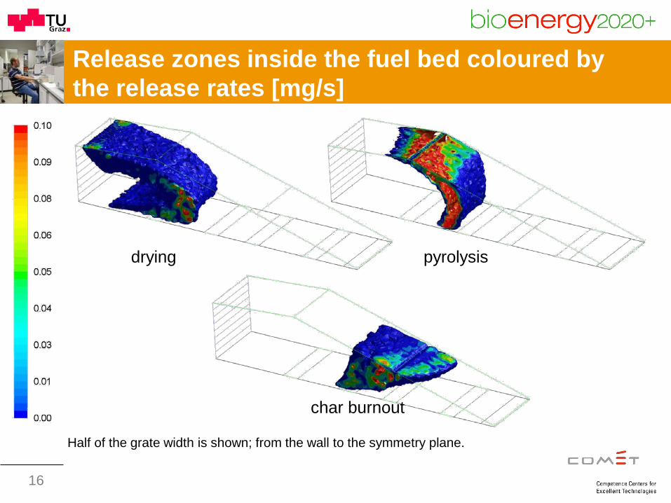
Release zones inside the fuel bed coloured by the release rates [mg/s]
char burnout
drying pyrolysis
16
Half of the grate width is shown; from the wall to the symmetry plane.
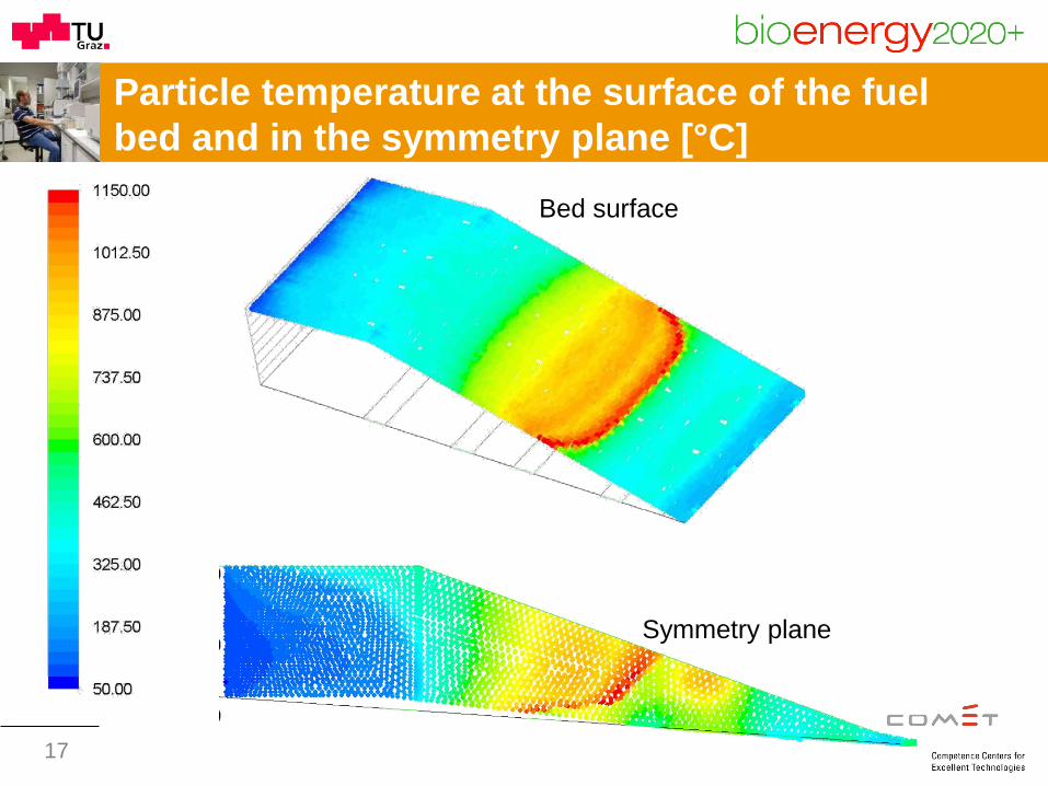
Particle temperature at the surface of the fuel bed and in the symmetry plane [°C]
Bed surface
Symmetry plane
17
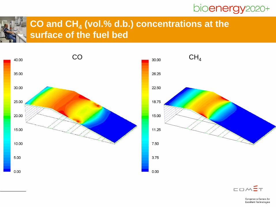
CO and CH4 (vol.% d.b.) concentrations at the surface of the fuel bed
CH4 CO
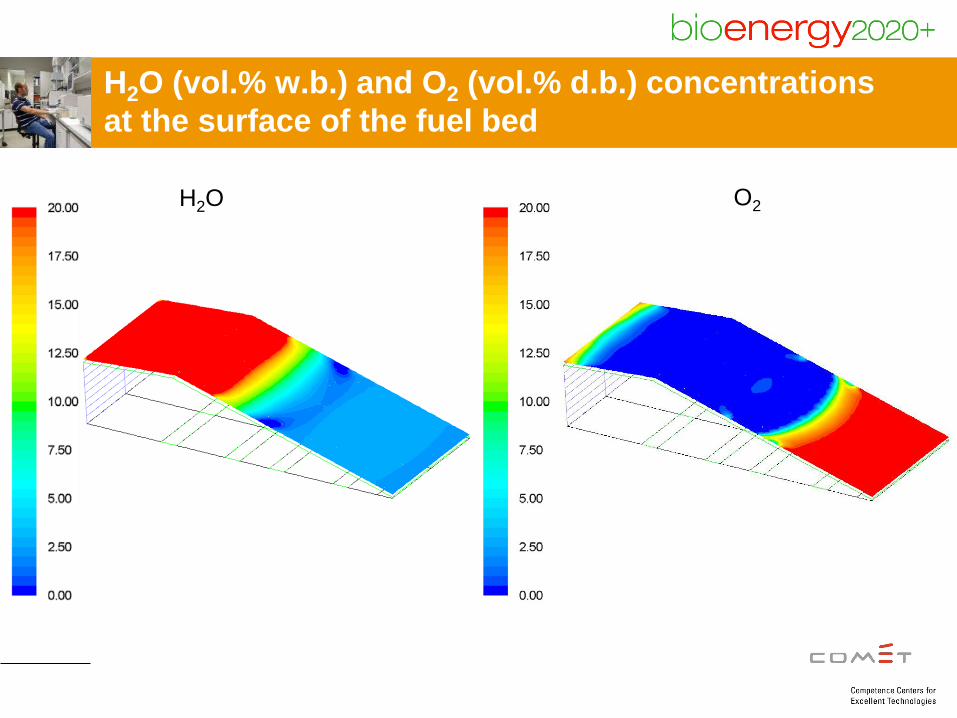
H2O (vol.% w.b.) and O2 (vol.% d.b.) concentrations at the surface of the fuel bed
H2O O2
20
Summary and conclusions
A CFD based model for packed bed combustion in biomass grate furnaces has been developed and successfully tested. The model has the following advantages:
■ Approximating the particle movements on the grate under consideration of particle-particle collisions (already applied for the fixed grate and is on-going for the moving grate).
■ Due to the consideration that the particles are thermally thick, the particle temperatures and consequently the mass loss rate during the thermal conversion of the particles can be better predicted.
■ The effect of particle related parameters (size, physical properties and moisture content) as well as operating conditions (air distribution below the grate, air pre-heating, flue gas re-circulation and air staging) can be investigated.
■ The packed bed modelling has been linked with an in-house developed gas phase CFD model for turbulent reactive flows in the combustion chamber. Hence, also the influence of flow, gas phase combustion and heat transfer from the combustion chamber on packed bed conversion is considered.
21
Outlook
Further developments planned:
■ Development of an enhanced heat transfer model for the packed bed (considering particle-particle radiation and conduction)
■ Application of an appropriate gas-solid multiphase model to simultaneously simulate the movement and the thermal conversion of the particles.
Thank you for your attention
Ramin Mehrabian
BIOENERGY 2020+ GmbH Inffeldgasse 21b, 8010 Graz, Austria
Tel.: +43 (0)316 8739232 E-mail: [email protected]