8. Geographic Data Modeling. Outline Definitions Data models / modeling GIS data models – Topology.

TS 7G – Development of 3D Cadastre Nurit Peres and Moshe Benhamu 3D Cadastre GIS – Geometry, Topology and Other Technical Considerations FIG Working Week 2009 Surveyors Key Role in Accelerated Development Eilat, Israel, 3-8 May 2009
1/14
3D Cadastre GIS – Geometry, Topology and Other Technical Considerations
Nurit PERES and Moshe BENHAMU, Israel
Key words: 3D Cadastre, GIS, Geo-information, Land management, Spatial planning SUMMARY Background: 3D Cadastre is an exciting, new and highly interesting topic for land administrations all over the world. It is also a high profile issue in Israel and the Survey of Israel – SOI is promoting the issue for several years. At the beginning of 2008 Sivan Design (www.sivandesign.com), a leader in the field of GIS, land registration, CAD and 3D simulation software solutions, had joined forces with SOI in order to design the 3D cadastre integration into the current Cadastre GIS in SOI. 3D Cadastre – technical considerations: This article will address some of the technical issues accompanying the transition from a 2D cadastre system to a 3D cadastre system. Many challenges arise on the way to a computerized 3D cadastre geographic system. We will refer to the following issues:
- Possible definitions for a 3D parcel – legal & technological aspects - Geometrical description of 3D objects in GIS - Single vs. multi layer model and its interaction with geometry considerations; a few
options will be reviewed - 3D topology for spatial parcels in GIS - Visualizing a 3D cadastre GIS
Although this work was done with the Israeli cadastre in mind, other land registration / cadastre systems are also in search for 3D cadastre GIS solutions and are in a similar struggle to implement such a solution.
TS 7G – Development of 3D Cadastre Nurit Peres and Moshe Benhamu 3D Cadastre GIS – Geometry, Topology and Other Technical Considerations FIG Working Week 2009 Surveyors Key Role in Accelerated Development Eilat, Israel, 3-8 May 2009
2/14
3D Cadastre GIS – Geometry, Topology and Other Technical Considerations
Nurit PERES and Moshe BENHAMU, Israel
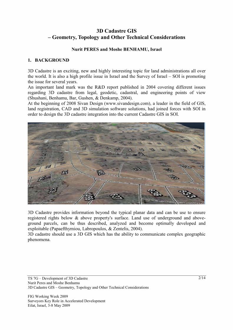
1. BACKGROUND 3D Cadastre is an exciting, new and highly interesting topic for land administrations all over the world. It is also a high profile issue in Israel and the Survey of Israel – SOI is promoting the issue for several years. An important land mark was the R&D report published in 2004 covering different issues regarding 3D cadastre from legal, geodetic, cadastral, and engineering points of view (Shushani, Benhamu, Bar, Gushen, & Denkamp, 2004). At the beginning of 2008 Sivan Design (www.sivandesign.com), a leader in the field of GIS, land registration, CAD and 3D simulation software solutions, had joined forces with SOI in order to design the 3D cadastre integration into the current Cadastre GIS in SOI.
3D Cadastre provides information beyond the typical planar data and can be use to ensure registered rights below & above property's surface. Land use of underground and above-ground parcels, can be thus described, analyzed and become optimally developed and exploitable (Papaefthymiou, Labropoulos, & Zentelis, 2004). 3D cadastre should use a 3D GIS which has the ability to communicate complex geographic phenomena.
TS 7G – Development of 3D Cadastre Nurit Peres and Moshe Benhamu 3D Cadastre GIS – Geometry, Topology and Other Technical Considerations FIG Working Week 2009 Surveyors Key Role in Accelerated Development Eilat, Israel, 3-8 May 2009
3/14
2. OBJECTIVES Legal and geodetic aspects of a 3D Cadastre were discussed before, Papaefthymiou, Labropoulos, & Zentelis, (2004), Stoter, (2004). The aim of this article is to examine the requirements and the design for a GIS system that will support 3D cadastre. As of today, commercial software does not support 3D entirely, some products have partial support but none have complete solution. There are different factors to consider: data structure, layers, processes, topology and visualization are the major ones… we will refer to those shortly after examining the basic definitions for 3D cadastre and spatial parcels. None of the existing GIS platforms can fully support a 3D cadastre and many of the open issues are complex and interdisciplinary. To deal with it requires knowledge in geodesy, geometry, databases, CAD, information systems, process analysis and of course GIS… We would like to offer a few conceptual alternatives for this path; the final selection of an alternative is out of the scope of this article since it highly depends on considerations such as cost and legislation. 3. 3D CADASTRE DEFINITIONS 3.1 Possible definitions for a 3D parcel 3.1.1 Ownership rights The decision regarding spatial owenership rights influence the relation between spatial and surface parcels and therefor influence the data structure, topologies and processes in a 3D cadastre GIS. Few of the alternatives for owenership rights are: 1. Restricting owenership on surface parcels to certain height and depth.
This requires a large legal change that is out of the scope of this research. There is also an open question regarding the level (or the height) of restriction.
2. Multilayer registration with joint owenership (similar to condominium registration in Israel). This is a system with wide experience in Israel, therefor easy and relativly low costed. It suits urban areas, but when spatial entities have no surface entity, a lot more complexity is added.
3. Registration of spatial entities seperatly from the current (surface) registration. A simple low cost system that will fit large entities with no surface usage, but place many lagislative dificulties in urban area. It may also cause confusion reagarding land rights and weeken land administration.
4. Multilayer registration with seperate owenership achieved by expropriation of underground / aboveground portions from surface parcels. This will lead to a unified and strong land administration, but it requires many changes in registration, which are costly.
TS 7G – Development of 3D Cadastre Nurit Peres and Moshe Benhamu 3D Cadastre GIS – Geometry, Topology and Other Technical Considerations FIG Working Week 2009 Surveyors Key Role in Accelerated Development Eilat, Israel, 3-8 May 2009
4/14
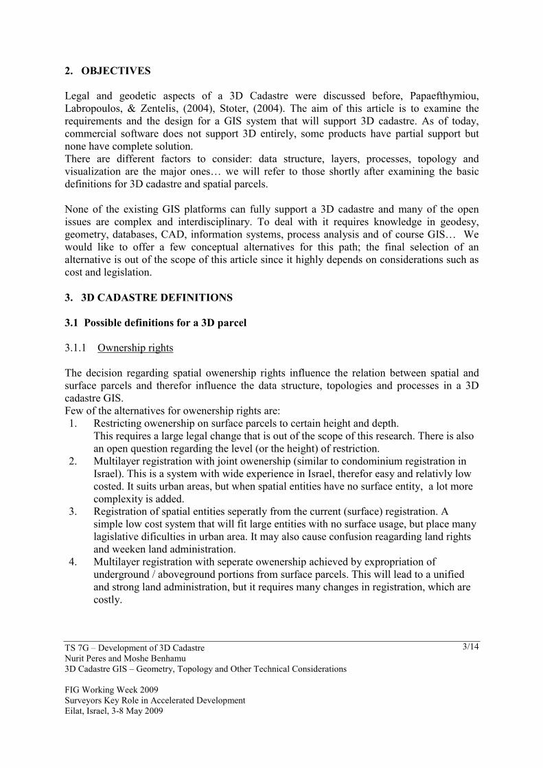
The SOI sees the forth alternative as a fair compromise between legal and technical requirements (Shushani, Benhamu, Bar, Gushen, & Denkamp, 2004). Each alternative has implications on data structure and topology rules. This alternative requires deviding each spatial parcels to sub-parcels in order to keep a connection between surface parcel owner and the relevant area (volume) of the spatial parcel. 3.1.2 Simple vs. complex shapes The definition of a 3D parcel is primarily derived from legislation (see above). From a technical point of view we may consider two maim types of geometric shapes: Full 3D geometric shape vs. 2.5D shape. Surface, underground and above ground parcels can be described in more than one way. The simplest one is to continue describe all in two dimensions. It is simple both perceptually and technically, but it is widely agreeable that it is not a sufficient way for the long run. Papaefthymiou, Labropoulos, & Zentelis, (2004), Stoter, (2004), Doytshe, Forrai, & Kirschner, (2001). Other alternatives require a change in all aspects concerning cadastre, public view, legislation, geodetic rules and the cadastre GIS. The most advanced option is holding parcels as a full 3D geometric shape with finite volume. It requires deep changes in all concerning aspects but allows complete use of the oppertunities in 3D cadastre. Full 3D parcels are geometry bodies with internal topology. In order to save these shapes in a database, it requires to make a decision regarding the geometric model. The geometric model should allow saving the shapes in a database with sufficient flexibilty to enable an easy way to updates and changes in parcel shape, size or location.
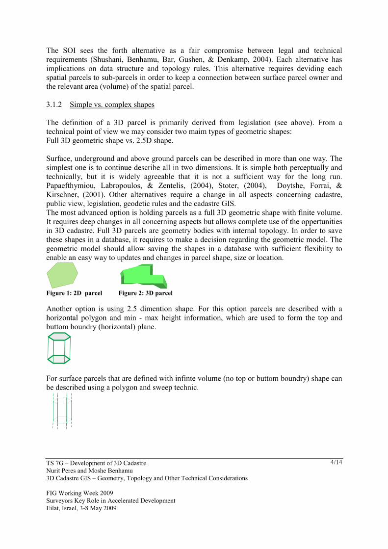
Figure 1: 2D parcel Figure 2: 3D parcel Another option is using 2.5 dimention shape. For this option parcels are described with a horizontal polygon and min - max height information, which are used to form the top and buttom boundry (horizontal) plane.
For surface parcels that are defined with infinte volume (no top or buttom boundry) shape can be described using a polygon and sweep technic.
TS 7G – Development of 3D Cadastre Nurit Peres and Moshe Benhamu 3D Cadastre GIS – Geometry, Topology and Other Technical Considerations FIG Working Week 2009 Surveyors Key Role in Accelerated Development Eilat, Israel, 3-8 May 2009
5/14
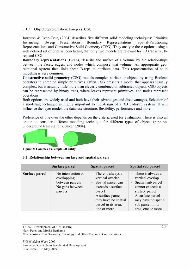
3.1.3 Object representation: B-rep vs. CSG Jarroush & Even-Tzur, (2004) describes five different solid modeling techniques: Primitive Instancing, Sweep Presentations, Boundary Representations, Spatial-Partitioning Representations and Constructive Solid Geometry (CSG). They analyze these options using a well defined set of criteria, concluding that only two models are relevant for 3D Cadastre, B-rep and CSG. Boundary representations (B-reps) describe the surface of a volume by the relationships between the faces, edges, and nodes which compose that volume. An appropriate geo-relational system then links these B-reps to attribute data. This representation of solid modeling is very common. Constructive solid geometry (CSG) models complex surface or objects by using Boolean operators to combine simple primitives. Often CSG presents a model that appears visually complex, but is actually little more than cleverly combined or subtracted objects. CSG objects can be represented by binary trees, where leaves represent primitives, and nodes represent operations Both options are widely used and both have their advantages and disadvantages. Selection of a modeling technique is highly important to the design of a 3D cadastre system. It will influence the layer model, the database structure, flexibility, performance and more. Preference of one over the other depends on the criteria used for evaluation. There is also an option to consider different modeling technique for different types of objects (pipe vs. underground train station), Stoter (2004).
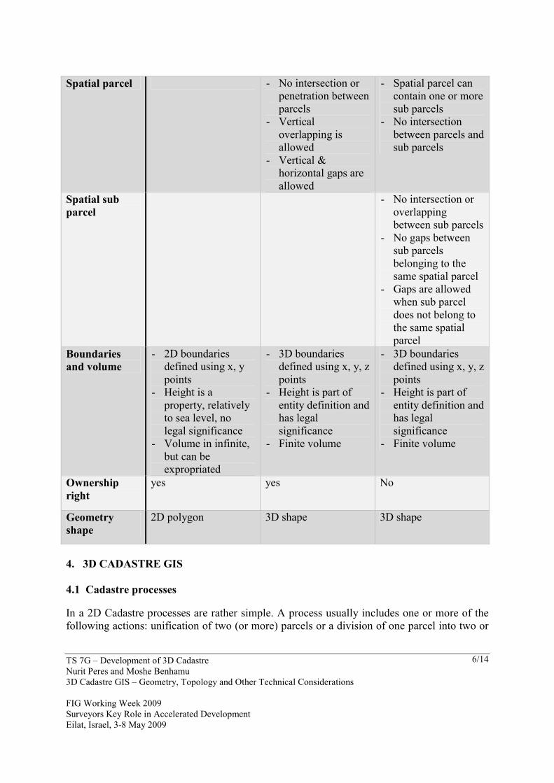
Figure 3: Complex vs. simple 3D entity 3.2 Relationship between surface and spatial parcels Surface parcel Spatial parcel Spatial sub parcel
Surface parcel - No intersection or overlapping between parcels
- No gaps between parcels
- There is always a vertical overlap
- Spatial parcel can exceeds a surface parcel
- A surface parcel may have no spatial parcel in its area, one or more
- There is always a vertical overlap
- Spatial sub parcel cannot exceeds a surface parcel
- A surface parcel may have no spatial sub parcel in its area, one or more
TS 7G – Development of 3D Cadastre Nurit Peres and Moshe Benhamu 3D Cadastre GIS – Geometry, Topology and Other Technical Considerations FIG Working Week 2009 Surveyors Key Role in Accelerated Development Eilat, Israel, 3-8 May 2009
6/14
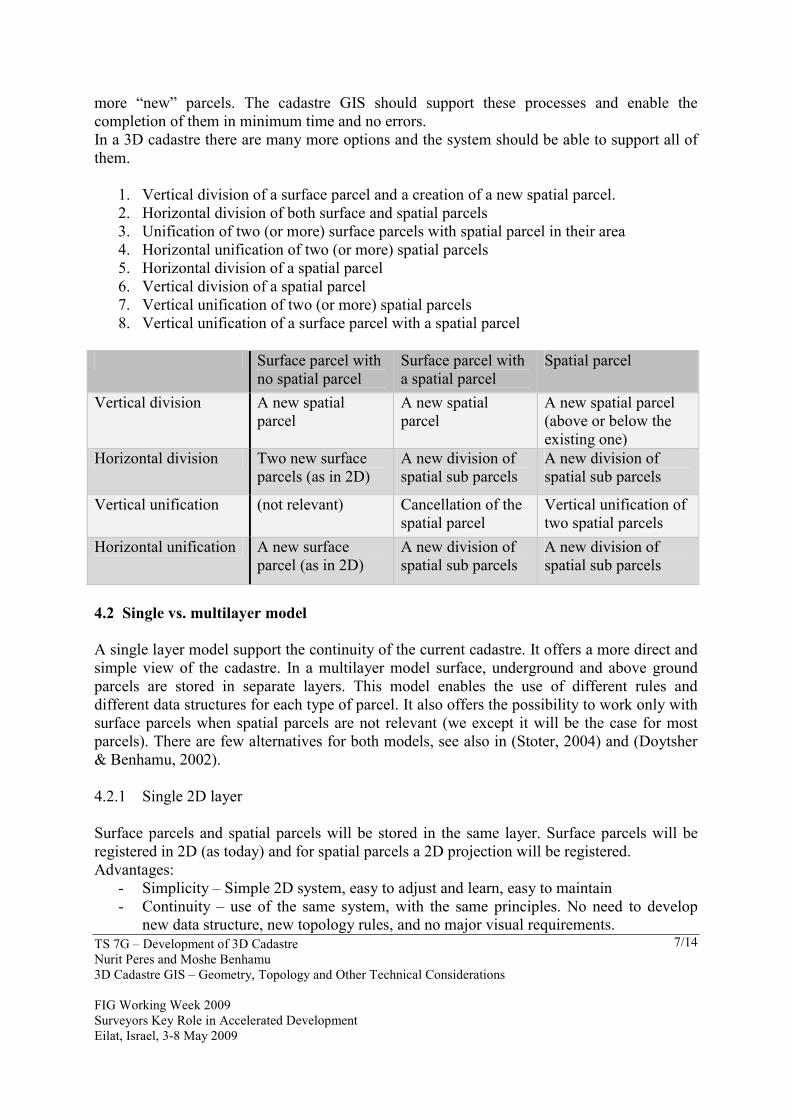
Spatial parcel - No intersection or
penetration between parcels
- Vertical overlapping is allowed
- Vertical & horizontal gaps are allowed
- Spatial parcel can contain one or more sub parcels
- No intersection between parcels and sub parcels
Spatial sub parcel
- No intersection or overlapping between sub parcels
- No gaps between sub parcels belonging to the same spatial parcel
- Gaps are allowed when sub parcel does not belong to the same spatial parcel
Boundaries and volume
- 2D boundaries defined using x, y points
- Height is a property, relatively to sea level, no legal significance
- Volume in infinite, but can be expropriated
- 3D boundaries defined using x, y, z points
- Height is part of entity definition and has legal significance
- Finite volume
- 3D boundaries defined using x, y, z points
- Height is part of entity definition and has legal significance
- Finite volume
Ownership right
yes yes No
Geometry shape
2D polygon 3D shape 3D shape
4. 3D CADASTRE GIS 4.1 Cadastre processes
In a 2D Cadastre processes are rather simple. A process usually includes one or more of the following actions: unification of two (or more) parcels or a division of one parcel into two or
TS 7G – Development of 3D Cadastre Nurit Peres and Moshe Benhamu 3D Cadastre GIS – Geometry, Topology and Other Technical Considerations FIG Working Week 2009 Surveyors Key Role in Accelerated Development Eilat, Israel, 3-8 May 2009
7/14
more “new” parcels. The cadastre GIS should support these processes and enable the completion of them in minimum time and no errors. In a 3D cadastre there are many more options and the system should be able to support all of them.
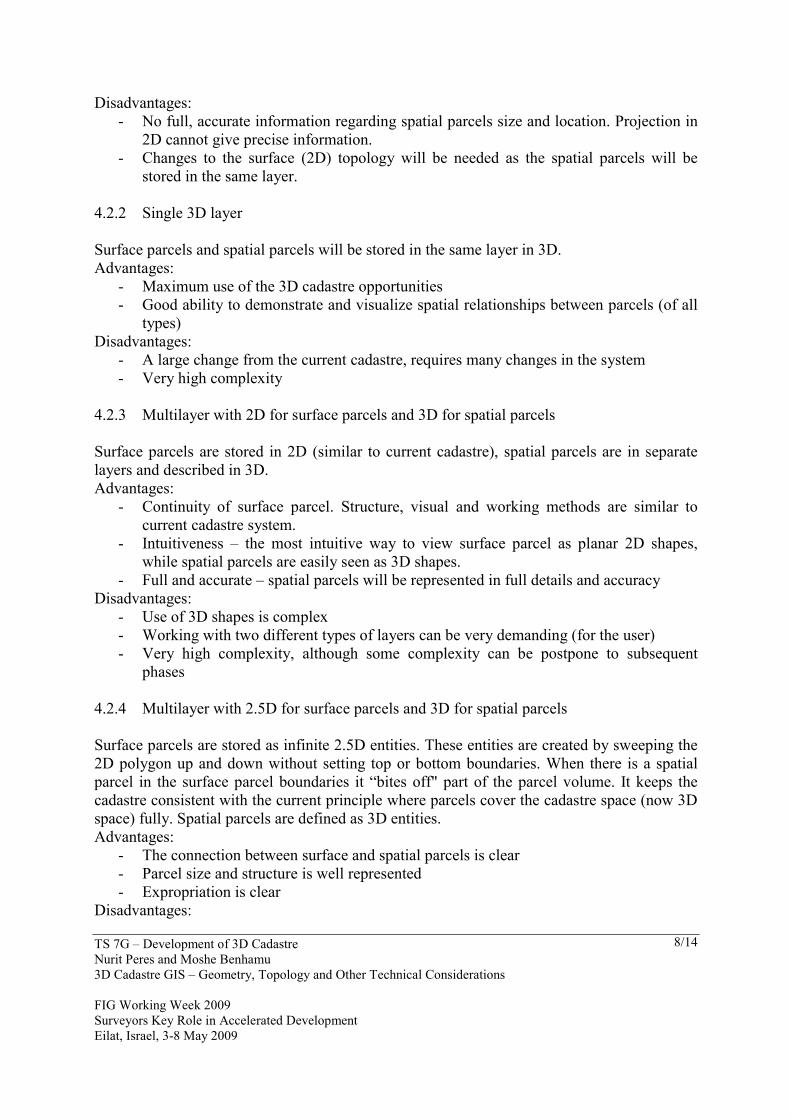
1. Vertical division of a surface parcel and a creation of a new spatial parcel. 2. Horizontal division of both surface and spatial parcels 3. Unification of two (or more) surface parcels with spatial parcel in their area 4. Horizontal unification of two (or more) spatial parcels 5. Horizontal division of a spatial parcel 6. Vertical division of a spatial parcel 7. Vertical unification of two (or more) spatial parcels 8. Vertical unification of a surface parcel with a spatial parcel
Surface parcel with
no spatial parcel Surface parcel with a spatial parcel
Spatial parcel
Vertical division A new spatial parcel
A new spatial parcel
A new spatial parcel (above or below the existing one)
Horizontal division Two new surface parcels (as in 2D)
A new division of spatial sub parcels
A new division of spatial sub parcels
Vertical unification (not relevant) Cancellation of the spatial parcel
Vertical unification of two spatial parcels
Horizontal unification A new surface parcel (as in 2D)
A new division of spatial sub parcels
A new division of spatial sub parcels
4.2 Single vs. multilayer model A single layer model support the continuity of the current cadastre. It offers a more direct and simple view of the cadastre. In a multilayer model surface, underground and above ground parcels are stored in separate layers. This model enables the use of different rules and different data structures for each type of parcel. It also offers the possibility to work only with surface parcels when spatial parcels are not relevant (we except it will be the case for most parcels). There are few alternatives for both models, see also in (Stoter, 2004) and (Doytsher & Benhamu, 2002).
4.2.1 Single 2D layer Surface parcels and spatial parcels will be stored in the same layer. Surface parcels will be registered in 2D (as today) and for spatial parcels a 2D projection will be registered. Advantages:
- Simplicity – Simple 2D system, easy to adjust and learn, easy to maintain - Continuity – use of the same system, with the same principles. No need to develop
new data structure, new topology rules, and no major visual requirements.
TS 7G – Development of 3D Cadastre Nurit Peres and Moshe Benhamu 3D Cadastre GIS – Geometry, Topology and Other Technical Considerations FIG Working Week 2009 Surveyors Key Role in Accelerated Development Eilat, Israel, 3-8 May 2009
8/14
Disadvantages: - No full, accurate information regarding spatial parcels size and location. Projection in
2D cannot give precise information. - Changes to the surface (2D) topology will be needed as the spatial parcels will be
stored in the same layer. 4.2.2 Single 3D layer Surface parcels and spatial parcels will be stored in the same layer in 3D. Advantages:
- Maximum use of the 3D cadastre opportunities - Good ability to demonstrate and visualize spatial relationships between parcels (of all
types) Disadvantages:
- A large change from the current cadastre, requires many changes in the system - Very high complexity
4.2.3 Multilayer with 2D for surface parcels and 3D for spatial parcels Surface parcels are stored in 2D (similar to current cadastre), spatial parcels are in separate layers and described in 3D. Advantages:
- Continuity of surface parcel. Structure, visual and working methods are similar to current cadastre system.
- Intuitiveness – the most intuitive way to view surface parcel as planar 2D shapes, while spatial parcels are easily seen as 3D shapes.
- Full and accurate – spatial parcels will be represented in full details and accuracy Disadvantages:
- Use of 3D shapes is complex - Working with two different types of layers can be very demanding (for the user) - Very high complexity, although some complexity can be postpone to subsequent
phases 4.2.4 Multilayer with 2.5D for surface parcels and 3D for spatial parcels Surface parcels are stored as infinite 2.5D entities. These entities are created by sweeping the 2D polygon up and down without setting top or bottom boundaries. When there is a spatial parcel in the surface parcel boundaries it “bites off" part of the parcel volume. It keeps the cadastre consistent with the current principle where parcels cover the cadastre space (now 3D space) fully. Spatial parcels are defined as 3D entities. Advantages:
- The connection between surface and spatial parcels is clear - Parcel size and structure is well represented - Expropriation is clear
Disadvantages:
TS 7G – Development of 3D Cadastre Nurit Peres and Moshe Benhamu 3D Cadastre GIS – Geometry, Topology and Other Technical Considerations FIG Working Week 2009 Surveyors Key Role in Accelerated Development Eilat, Israel, 3-8 May 2009
9/14
- Parcels modeling is complex and requires complex data structure - Complex and new topology rules are required - No continuity of the current cadastre
4.2.5 2D for surface parcels with projection of spatial parcels boundaries and pointer to
more information. Surface parcels will be registered in 2D (as now) and for spatial parcels a 2D projection will be registered. In addition, there will be a direct linkage to the full CAD information of the spatial parcels from both projection and relevant surface parcel. Advantages:
- Simplicity – Simple 2D system, easy to adjust, learn, and maintain - Continuity – use of the same system, with the same principles. No need to develop
new data structure, new topology rules, and no major visual requirements. Disadvantages:
- Changes to the surface (2D) topology will be needed as the spatial parcels will be stored in the same layer.
- No spatial queries - Transferring to CAD for more information is complicated and un-friendly
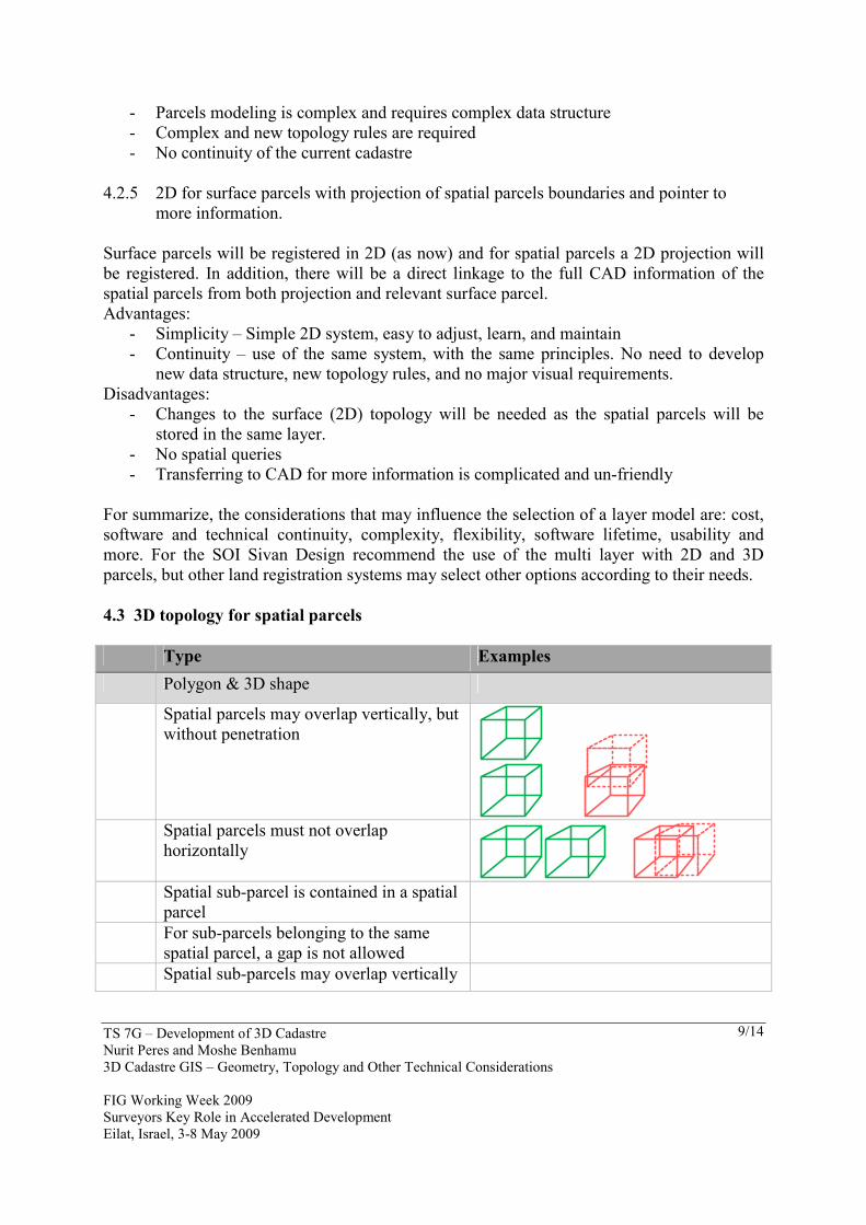
For summarize, the considerations that may influence the selection of a layer model are: cost, software and technical continuity, complexity, flexibility, software lifetime, usability and more. For the SOI Sivan Design recommend the use of the multi layer with 2D and 3D parcels, but other land registration systems may select other options according to their needs. 4.3 3D topology for spatial parcels Type Examples Polygon & 3D shape
Spatial parcels may overlap vertically, but without penetration
Spatial parcels must not overlap
horizontally
Spatial sub-parcel is contained in a spatial parcel
For sub-parcels belonging to the same spatial parcel, a gap is not allowed
Spatial sub-parcels may overlap vertically
TS 7G – Development of 3D Cadastre Nurit Peres and Moshe Benhamu 3D Cadastre GIS – Geometry, Topology and Other Technical Considerations FIG Working Week 2009 Surveyors Key Role in Accelerated Development Eilat, Israel, 3-8 May 2009
10/14
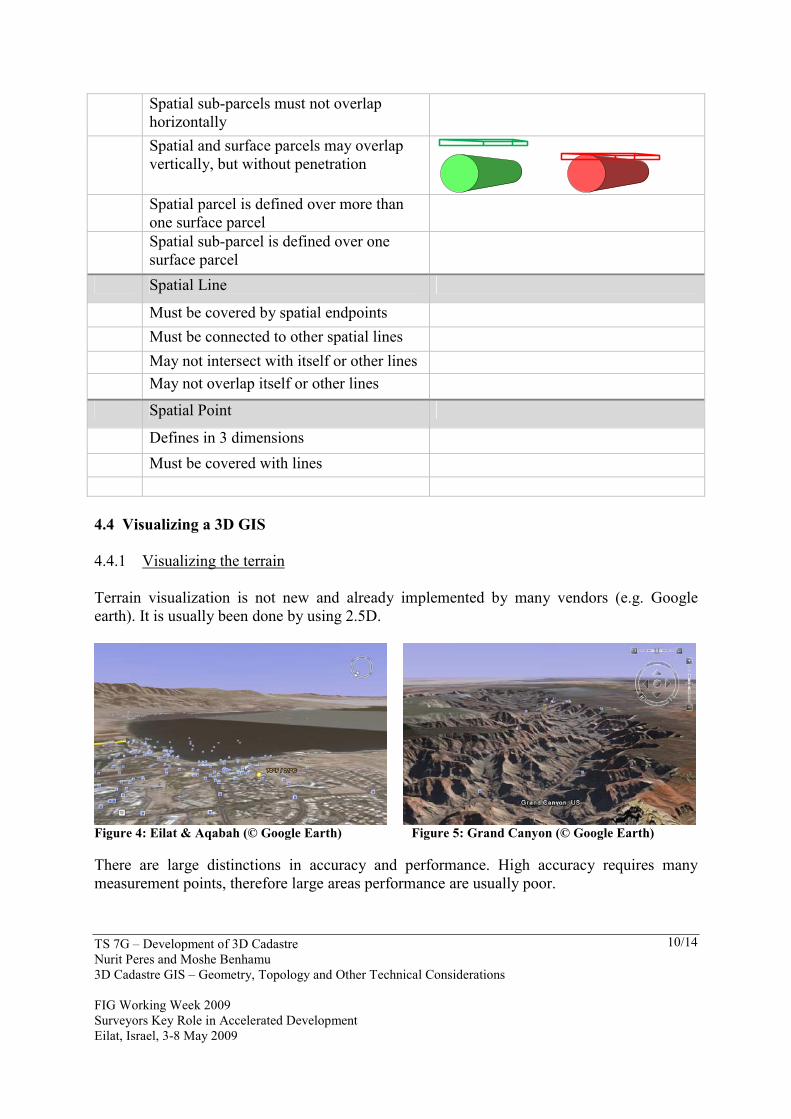
Spatial sub-parcels must not overlap horizontally
Spatial and surface parcels may overlap vertically, but without penetration
Spatial parcel is defined over more than
one surface parcel
Spatial sub-parcel is defined over one surface parcel
Spatial Line
Must be covered by spatial endpoints Must be connected to other spatial lines May not intersect with itself or other lines May not overlap itself or other lines
Spatial Point
Defines in 3 dimensions Must be covered with lines 4.4 Visualizing a 3D GIS
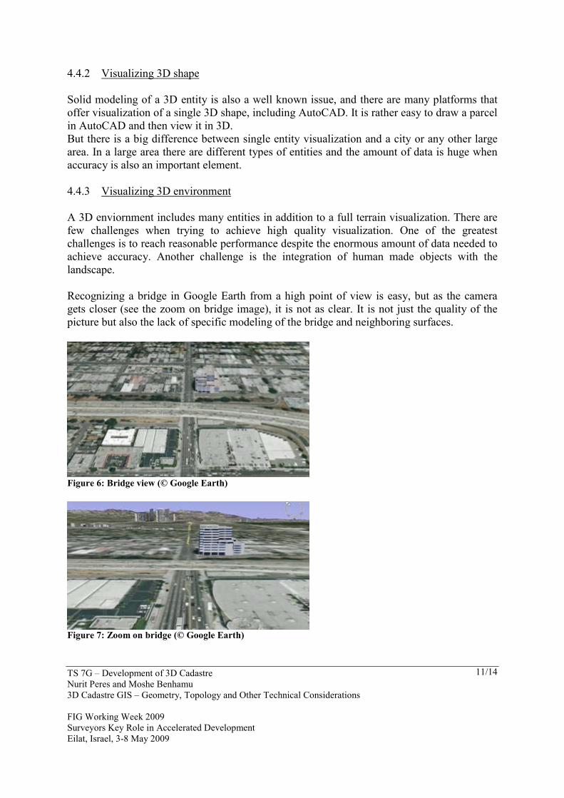
4.4.1 Visualizing the terrain Terrain visualization is not new and already implemented by many vendors (e.g. Google earth). It is usually been done by using 2.5D.
Figure 4: Eilat & Aqabah (© Google Earth) Figure 5: Grand Canyon (© Google Earth) There are large distinctions in accuracy and performance. High accuracy requires many measurement points, therefore large areas performance are usually poor.
TS 7G – Development of 3D Cadastre Nurit Peres and Moshe Benhamu 3D Cadastre GIS – Geometry, Topology and Other Technical Considerations FIG Working Week 2009 Surveyors Key Role in Accelerated Development Eilat, Israel, 3-8 May 2009
11/14
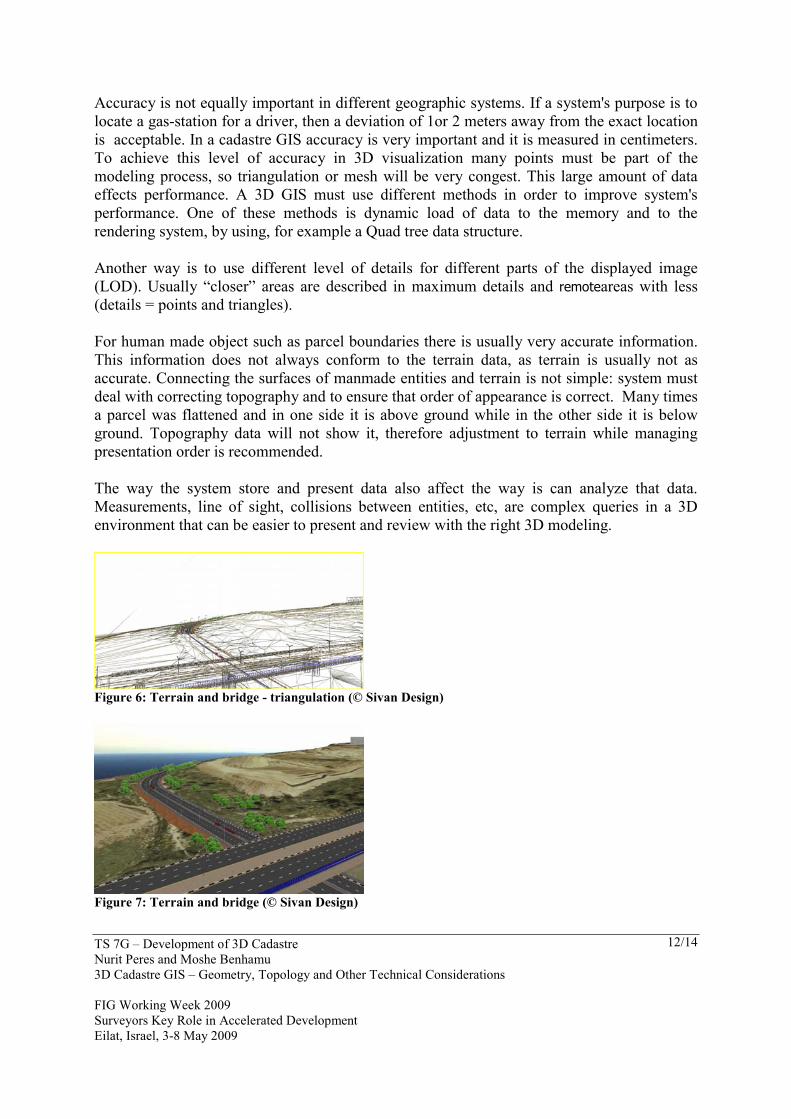
4.4.2 Visualizing 3D shape Solid modeling of a 3D entity is also a well known issue, and there are many platforms that offer visualization of a single 3D shape, including AutoCAD. It is rather easy to draw a parcel in AutoCAD and then view it in 3D. But there is a big difference between single entity visualization and a city or any other large area. In a large area there are different types of entities and the amount of data is huge when accuracy is also an important element. 4.4.3 Visualizing 3D environment A 3D enviornment includes many entities in addition to a full terrain visualization. There are few challenges when trying to achieve high quality visualization. One of the greatest challenges is to reach reasonable performance despite the enormous amount of data needed to achieve accuracy. Another challenge is the integration of human made objects with the landscape. Recognizing a bridge in Google Earth from a high point of view is easy, but as the camera gets closer (see the zoom on bridge image), it is not as clear. It is not just the quality of the picture but also the lack of specific modeling of the bridge and neighboring surfaces.
Figure 6: Bridge view (© Google Earth)
Figure 7: Zoom on bridge (© Google Earth)
TS 7G – Development of 3D Cadastre Nurit Peres and Moshe Benhamu 3D Cadastre GIS – Geometry, Topology and Other Technical Considerations FIG Working Week 2009 Surveyors Key Role in Accelerated Development Eilat, Israel, 3-8 May 2009
12/14
Accuracy is not equally important in different geographic systems. If a system's purpose is to locate a gas-station for a driver, then a deviation of 1or 2 meters away from the exact location is acceptable. In a cadastre GIS accuracy is very important and it is measured in centimeters. To achieve this level of accuracy in 3D visualization many points must be part of the modeling process, so triangulation or mesh will be very congest. This large amount of data effects performance. A 3D GIS must use different methods in order to improve system's performance. One of these methods is dynamic load of data to the memory and to the rendering system, by using, for example a Quad tree data structure. Another way is to use different level of details for different parts of the displayed image (LOD). Usually “closer” areas are described in maximum details and remoteareas with less (details = points and triangles). For human made object such as parcel boundaries there is usually very accurate information. This information does not always conform to the terrain data, as terrain is usually not as accurate. Connecting the surfaces of manmade entities and terrain is not simple: system must deal with correcting topography and to ensure that order of appearance is correct. Many times a parcel was flattened and in one side it is above ground while in the other side it is below ground. Topography data will not show it, therefore adjustment to terrain while managing presentation order is recommended. The way the system store and present data also affect the way is can analyze that data. Measurements, line of sight, collisions between entities, etc, are complex queries in a 3D environment that can be easier to present and review with the right 3D modeling.
Figure 6: Terrain and bridge - triangulation (© Sivan Design)
Figure 7: Terrain and bridge (© Sivan Design)
TS 7G – Development of 3D Cadastre Nurit Peres and Moshe Benhamu 3D Cadastre GIS – Geometry, Topology and Other Technical Considerations FIG Working Week 2009 Surveyors Key Role in Accelerated Development Eilat, Israel, 3-8 May 2009
13/14
Any 3D Cadastre geographic system will have to address these issues. It should support 3D cadastre processes, model 3D parcels and store the relevant data in the database, keeps a layer model which is relevant to legislations and other needs, support 3D topology rules and enable both accurate and high performance visualization. It is not an easy task. Each one of these issues requires carful considering and multidisciplinary thinking, but it can be done. REFERENCES
Coors, V. (2003). 3D-GIS in networking environments. Computers, Environment and Urban Systems , (27) 345–357.
Doytshe, Y., Forrai, J., & Kirschner, G. (2001). Initiatives Toward a 3D GIS-Related Multi-Layer Digital Cadastre in Israel. Seoul, Korea: In Proceedings FIG.
Doytsher, Y., & Benhamu, M. (2002). A Multilayer 3D Cadastre: Problems and Solutions. In Proceedings FIG. Washington D.C: ACSM/ASPRS.
Jarroush, J., & Even-Tzur, G. (2004). Constructive Solid Geometry as the Basis of 3D Future Cadastre . In Proceedings FIG . Athens, Greece, .
Papaefthymiou, M., Labropoulos, T., & Zentelis, P. (2004). 3-D Cadastre in Greece. Legal, Physical and Practical Issues. Application on Santorini Island. In Proceedings FIG. Athens, Greece.
Stoter, J. E. (2004). 3D Cadastre. Geodesy 57 .
Shushani, U., Benhamu, M., Bar, R., Gushen, A., & Denkamp, S. (2004). R&D 3D Cadastre final report. Tel Aviv: The SOI (In Hebrew). BIOGRAPHICAL NOTES Nurit Peres is a product manager at Sivan Design. She has years of experience in analysis and design of information systems, including GIS and Web applications. Nurit has MA in Cognitive Psychology from Tel Aviv University (with honor) and a System Analysis diploma from the Technion – The Israeli Institute of Technology. Moshe Benhamu is the Head Division of 3D Cadastre – Survey of Israel (2004-2008). Since 2008 he is the Head Department of photogrammetry in Survey of Israel. He graduated the Technion – The Israeli Institute of Technology in Civil Engineering in 1995, and received a M.Sc. (1998) in Geodetic Engineering also from the Technion. His main fields of Interest include GIS, Cadastre, 3D Cadastre and Photogrammetry.

TS 7G – Development of 3D Cadastre Nurit Peres and Moshe Benhamu 3D Cadastre GIS – Geometry, Topology and Other Technical Considerations FIG Working Week 2009 Surveyors Key Role in Accelerated Development Eilat, Israel, 3-8 May 2009
14/14
CONTACTS Nurit Peres Sivan Design 17th Ha’tidhar st. Raanana 43656 ISRAEL Tel. +972-9-7427991 Fax + 972-9-7469295 Email: [email protected] Web site: www.sivandesign.com Moshe Benhamu Survey of Israel Head Department of photogrammetry 1 Lincoln st. Tel-Aviv, Postal Code 65220 ISRAEL Tel. + 972 3 6231927 Fax + 972 3 5624766 E-mail: [email protected]