3b. Performance characterization of fuel cell systems (Mench, ch. 4) 1...
24
1. Polarization curve 2. Activation polarization 3. Ohmic polarization 4. Concentration polarization 5. Other polarization losses 6. Polarization curve model 3b. Performance characterization of fuel cell systems (Mench, ch. 4)
Transcript of 3b. Performance characterization of fuel cell systems (Mench, ch. 4) 1...
1. Polarization curve2. Activation polarization3. Ohmic polarization4. Concentration polarization5. Other polarization losses6. Polarization curve model
3b. Performance characterization of fuel cell systems (Mench, ch. 4)
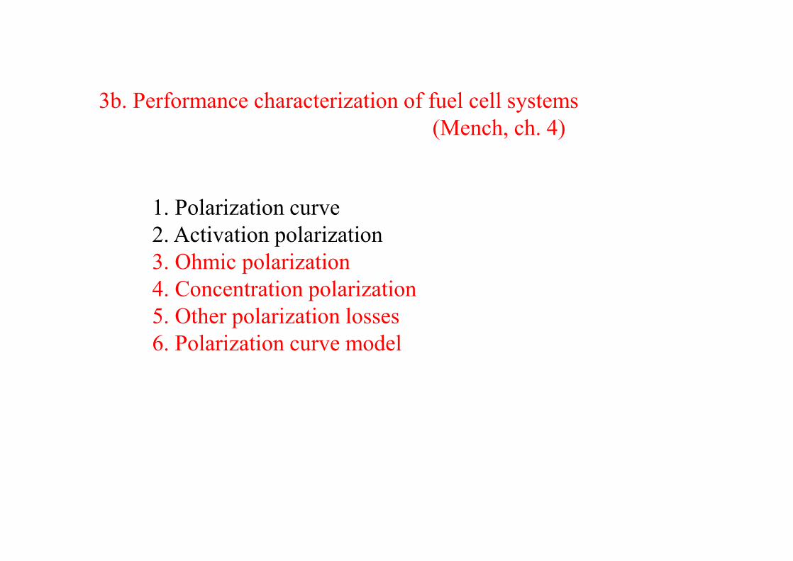
(Mench, ch. 2)
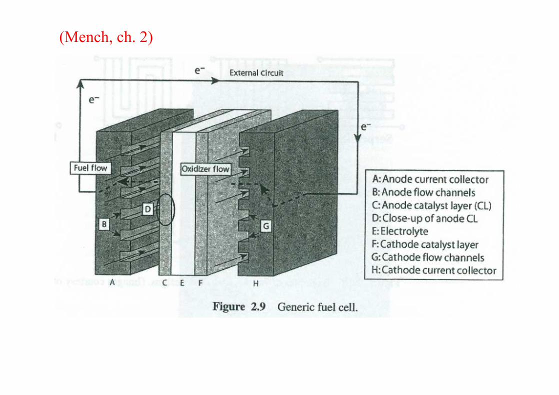
3. Region II: ohmic polarization-At moderate current densities, a primarily linear region (Region II) → reduction in voltage is dominated by internal ohmic losses (ηr) through the fuel cell, resulting in the nearly linear behavior, although activation and concentration polarization in this region are still present
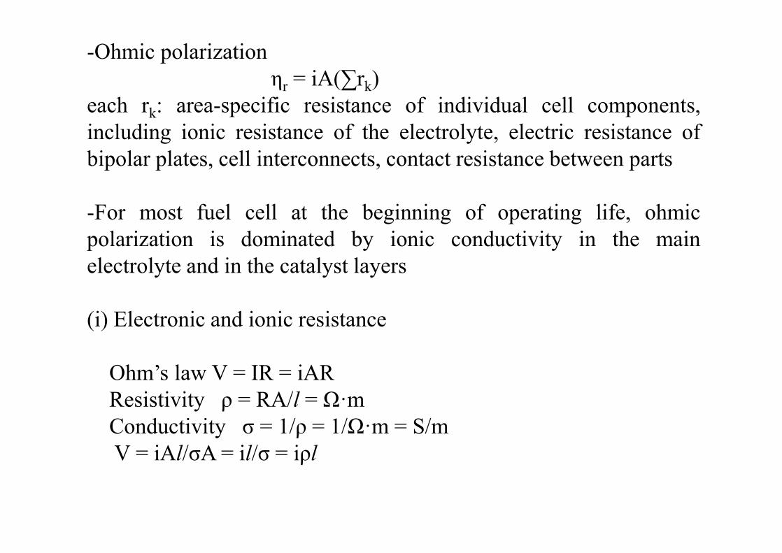
-Ohmic polarizationηr = iA(∑rk)
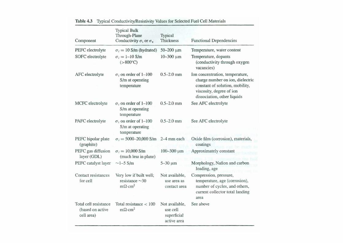
each rk: area-specific resistance of individual cell components,including ionic resistance of the electrolyte, electric resistance ofbipolar plates, cell interconnects, contact resistance between parts
-For most fuel cell at the beginning of operating life, ohmicpolarization is dominated by ionic conductivity in the mainelectrolyte and in the catalyst layers
(i) Electronic and ionic resistance
Ohm’s law V = IR = iARResistivity ρ = RA/l = Ω·mConductivity σ = 1/ρ = 1/Ω·m = S/mV = iAl/σA = il/σ = iρl
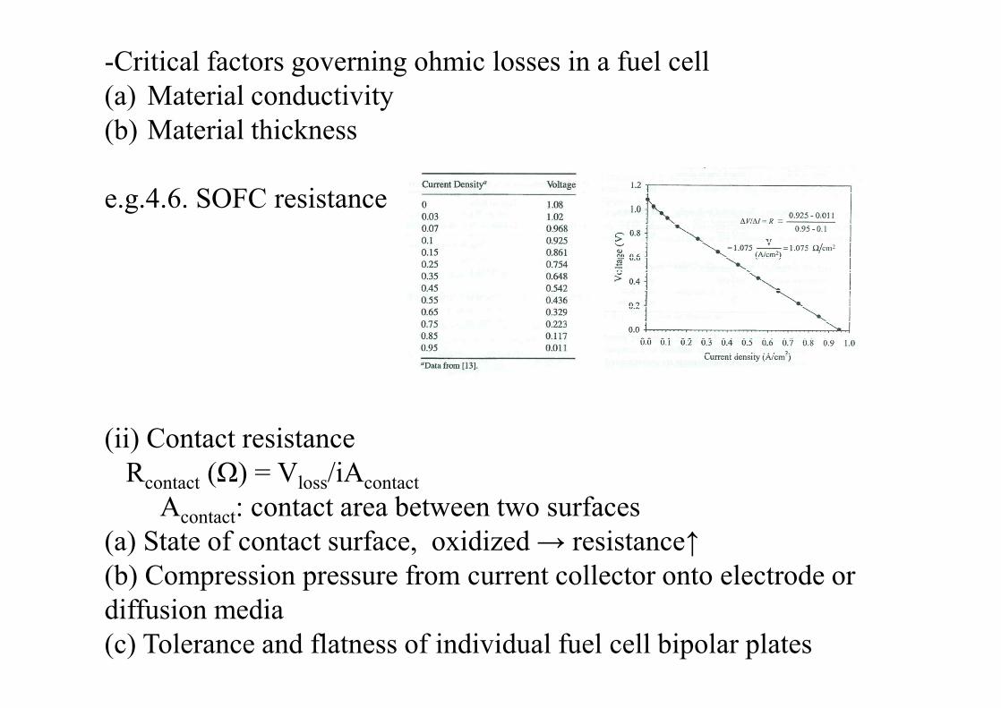
-Critical factors governing ohmic losses in a fuel cell(a) Material conductivity(b) Material thickness
e.g.4.6. SOFC resistance
(ii) Contact resistanceRcontact (Ω) = Vloss/iAcontact
Acontact: contact area between two surfaces(a) State of contact surface, oxidized → resistance↑ (b) Compression pressure from current collector onto electrode or diffusion media(c) Tolerance and flatness of individual fuel cell bipolar plates

e.g.4.6. PEFC, OCV: 1.0 V. electrolyte conductivity 8.3 S/m. catalyst layers: 40% ionomer equivalent, 30μm thick.(a) Nafion 112 (51 μm thick), (b) Nafion 117 (178 μm thick) → max. current density? (ignoring other polarizations besides ohmic losses)
cf. many high T FCs are limited by the ionic conductivity of electrolyte, because mass transport and kinetics are facilitated at high T. Also relative importance of the electrolyte in the overall loss.e.g.) 18 μm electrolyte in PEFC → electrode resistance layer than electrolyte

(iii) Cell assembly
-beyond design point → plastic deformation-presence of liquid water does not influence the contact resistance since pure water is nonconductive
e.g.4.8. equivalent ohmic lossionic resistance network for a single PEFC
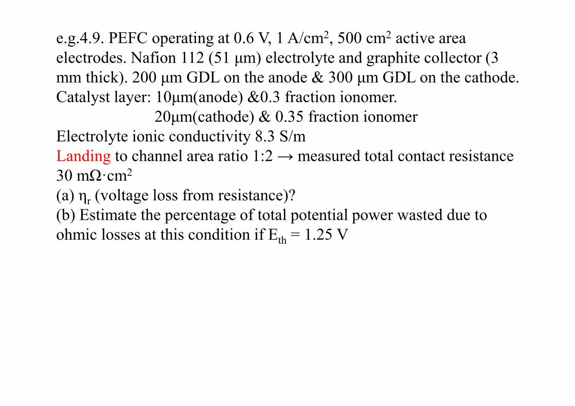
e.g.4.9. PEFC operating at 0.6 V, 1 A/cm2, 500 cm2 active area electrodes. Nafion 112 (51 μm) electrolyte and graphite collector (3 mm thick). 200 μm GDL on the anode & 300 μm GDL on the cathode.Catalyst layer: 10μm(anode) &0.3 fraction ionomer.
20μm(cathode) & 0.35 fraction ionomerElectrolyte ionic conductivity 8.3 S/mLanding to channel area ratio 1:2 → measured total contact resistance 30 mΩ·cm2
(a) ηr (voltage loss from resistance)?(b) Estimate the percentage of total potential power wasted due to ohmic losses at this condition if Eth = 1.25 V

4. Region III: concentration polarization
-a reduction in the reactant surface concentration, which reduces the thermodynamic voltage from the Nernst equation and the exchange current density from the Butler-Volmer equation

-Transport of reactant
-a rate of transport of reactant
→ concentration polarization
-Restriction of the rate of transport to the electrode(a) gas-phase diffusion limitation: diffusion rate…(b) liquid-phase accumulation and pore blockage limitation: in PEFC, liquid water accumulation and pore blockage in the pores og the electrolyte, diffusion media, or flow channel “flooding”(c) build-up inert gases: as O2 consumed in cathode, N2 mole fraction↑ → inert boundary-layer-restricting reaction(d) Surface blockage by impurity coverage: CO poisoning
i0 = (4.31)
-from a combination of the thermodynamic(Nernst) and exchange current density dependency (eq.4.31), the voltage adjustment as a result of the hange in oxygen concentration from the reference value(1 atm) on the cathode
γ: oxygen reduction reaction order with respect to O2 partial pressure at constant overpotential (0.6~0.75 for PEFC)-assume γ~0.75
→ 47 mV gain in potential from switching from dry air(21% O2) to pure oxygen at 353K-On the anode,
reaction order from hydrogen: 0.25~1

-In practice, the anode hydrogen concentration effect is often neglected for several reasons(a) Diffusivity of hydrogen is much more rapid than oxygen, especially in higher T fuel cells, so that transport limitation is rare.(b) HOR kinetics are facile compared to the cathode so that the cathode polarization typically dominates(c) In PEFC, liquid blockage(electrode flooding) occurs more frequently on the cathode
-At higher current densities, the mass transport limitations can reduce the concentration of the reactants at the catalyst surface to well below the flow field channel concentration and cause a sharp decline in the output voltage → mass concentration polarization (ηm) (Region III)

-Voltage at an electrode for concentration changes in reactant R from some state 2 to state 1
-mass-limiting current density (il)assume the surface concentration(cR) is zero at the limiting state and decreases linearly from state 1 to state 2
If assume rxn occurs only at the catalyst layer interface, which is true for high-current density mass-transport-limited rxn, and we neglect kinetic effects, we are left with the Nernst equation at each electrode
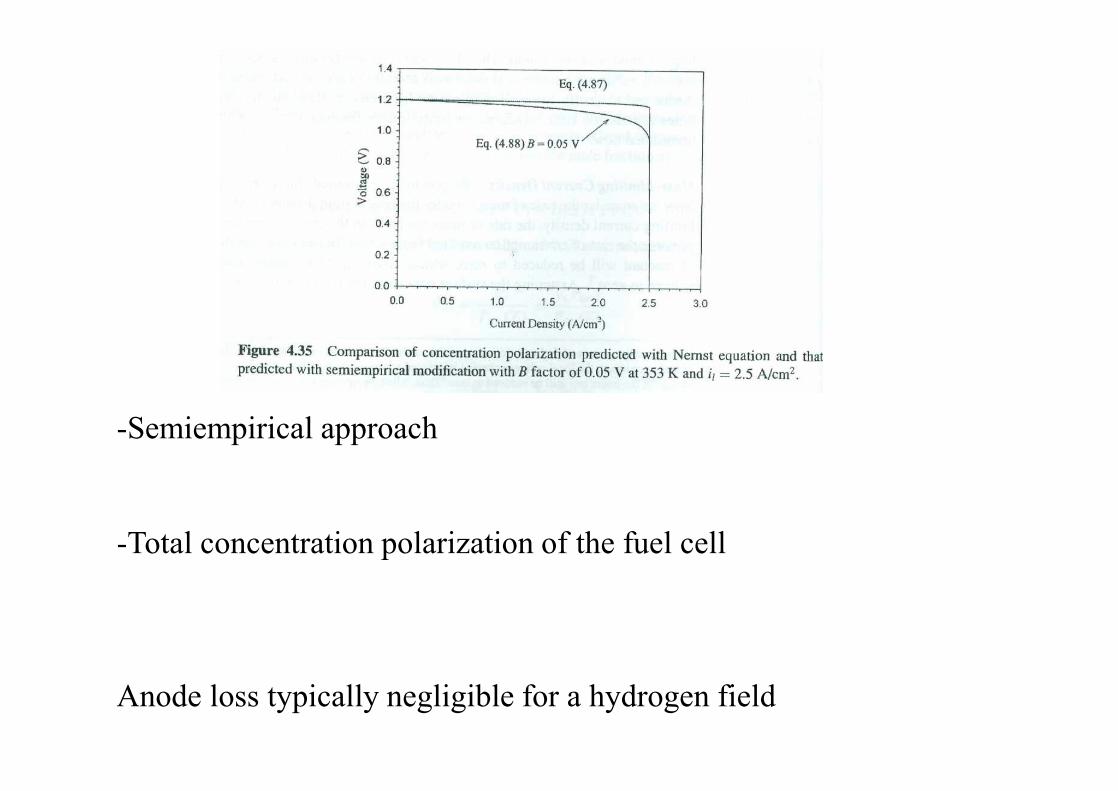
-Semiempirical approach
-Total concentration polarization of the fuel cell
Anode loss typically negligible for a hydrogen field

e.g.4.11. anode mass-transport limited current density: 15 A/cm2
cathode mass-transport limited current density: 2.5 A/cm2
→ determine the anode and cathode concentration polarization at 0.1 and 1.0 A/cm2. Assume B factor is 0.045 V on both electrodes

-Alternate empirical approach
-Flow stoichiometry

5. Region IV: other polarization losses
-the departure from the theoretical OCV(a) Electrical short circuits in the fuel cell(b) Crossover of reactants through the electrolyte and subsequent mixed-potential rxn at the opposite electrode

(i) Electrical shorts-current is short circuited through the electrolyte transference number (ti): the ratio of electrolyte ionic conductivities
to the total conductivity (ionic + electronic → mixed conductivity of the electrolyte)
(ii) Species crossover-0.2 V loss at the open circuit in PEFC = ~20% efficiency loss-DMFC(direct methanol FC) → liquid fuel with water → more readily crossover → actual OCV of 0.7 V (~1.2 V predicted)-PEFC: anode → negligible oxygen crossover in anode (due to low ORR kinetics). Cathode → higher effect of H2 crossover → mixed rxn & lowered OCV

-To limit reactant crossover• Change in material properties of electrolyte (D↓): less permeable to
the reactants → porosity, composite
• Use of thicker electrolyte (x↑)• Alteration of morphology or structure of porous media/or catalyst
layers to limit diffusion through electrolyte: diffusion barrier• Alteration of electrolyte composition to consume crossover before
reacting electrode. E.g. Pt in electrolyte• Recirculation of liquid electrolyte
-Modeling crossover losses
Semiempirial basiscrossover current density ix → cathode current i + ixcathode kinetic overpotential in the absence of concentration effects
e.g. hydrogen crossover loss 3.3 mA/cm2
→ mass crossover rate of H2 through membrane?Calculate cathode activation overpotential loss at open-circuit and 1 A/cm2 as a function of cathode exchange current density (assume αc = 1.5 at 353K, FC 50 cm2 area)
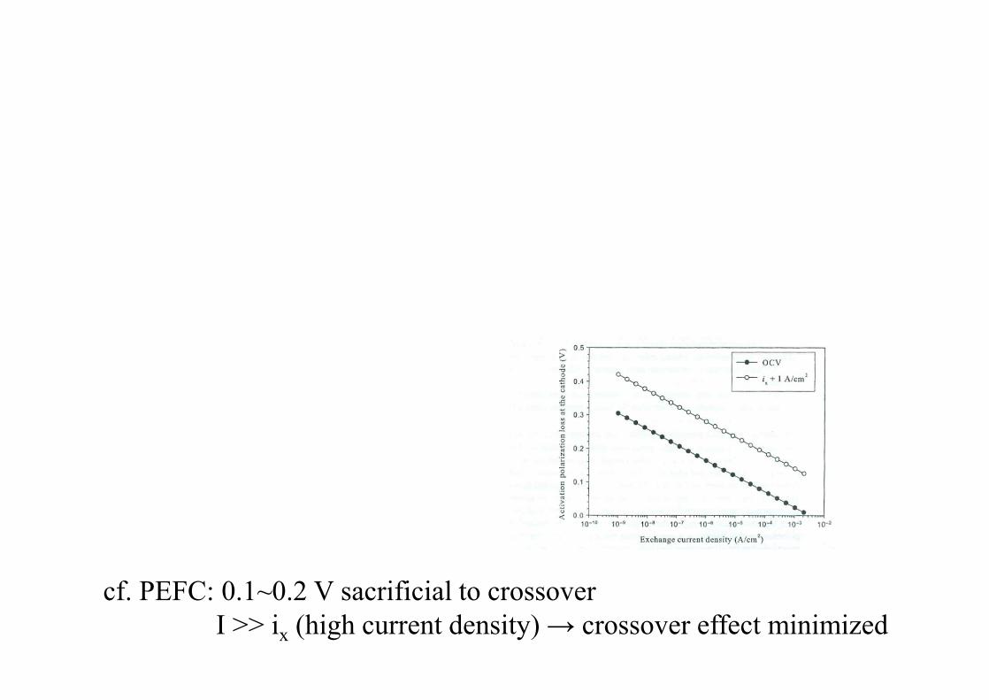
cf. PEFC: 0.1~0.2 V sacrificial to crossoverI >> ix (high current density) → crossover effect minimized
6. Polarization curve model summary
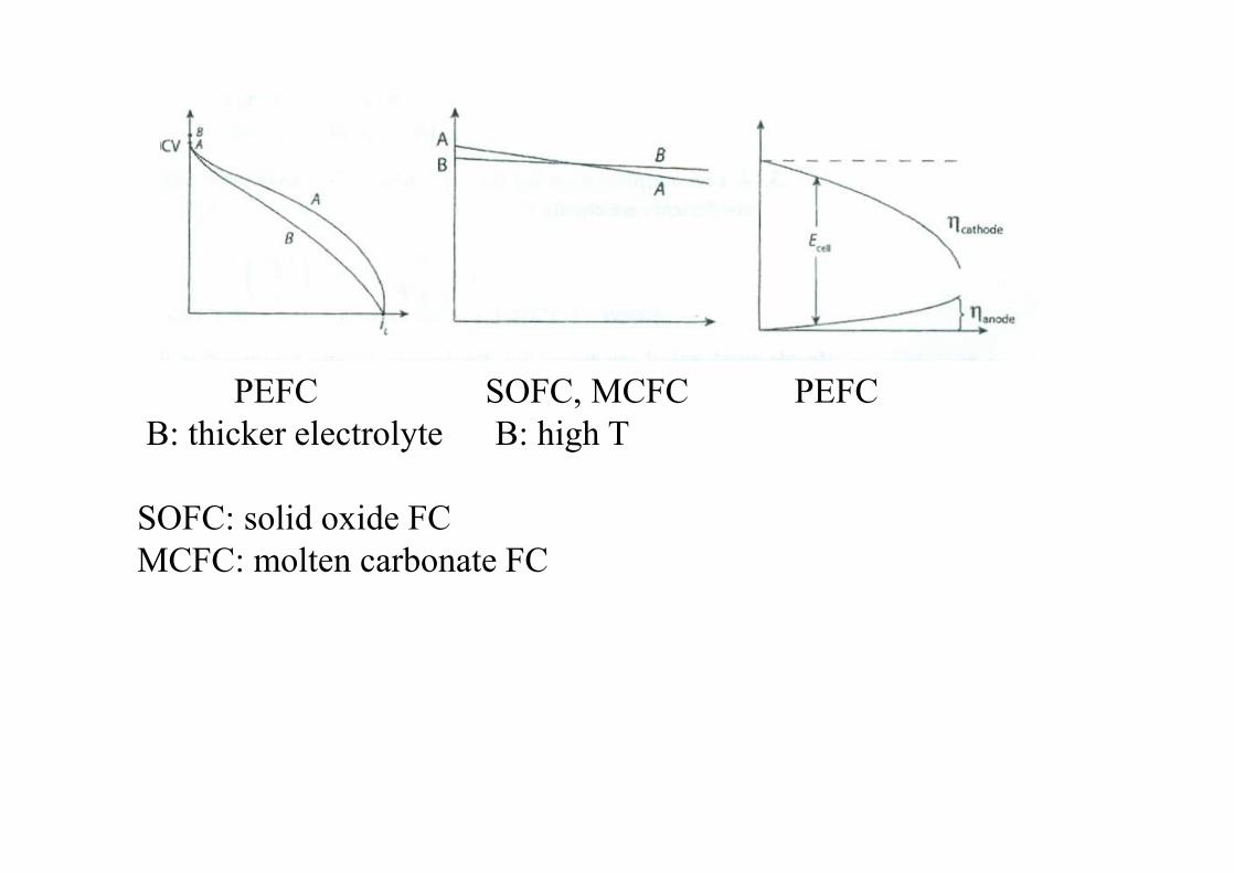
PEFC SOFC, MCFC PEFCB: thicker electrolyte B: high T
SOFC: solid oxide FCMCFC: molten carbonate FC