3A2152B - LSR Select, Instructions - Parts, English€¦ · 3A2152B EN Instructions - Parts LSR...
112
3A2152B EN Instructions - Parts LSR Select Plural-component, variable-ratio proportioner. For dispensing liquid silicone rubber into injection molds. For professional use only. Not approved for use in explosive atmospheres or hazardous locations. See page 3 for model information, including maximum work- ing pressure and approvals. Important Safety Instructions Read all warnings and instructions in this manual. Save these instructions. ti18092a
Transcript of 3A2152B - LSR Select, Instructions - Parts, English€¦ · 3A2152B EN Instructions - Parts LSR...

3A2152BEN
Instructions - Parts
LSR SelectPlural-component, variable-ratio proportioner. For dispensing liquid silicone rubber into injection molds. For professional use only.
Not approved for use in explosive atmospheres or hazardous locations.
See page 3 for model information, including maximum work-ing pressure and approvals.
Important Safety InstructionsRead all warnings and instructions in this manual. Save these instructions.
ti18092a

Contents
2 3A2152B
ContentsContents . . . . . . . . . . . . . . . . . . . . . . . . . . . . . . . . . . 2Related Manuals . . . . . . . . . . . . . . . . . . . . . . . . . . . 3Models . . . . . . . . . . . . . . . . . . . . . . . . . . . . . . . . . . . 3Warnings . . . . . . . . . . . . . . . . . . . . . . . . . . . . . . . . . 4Important Two-Component Material Information . 6
Keep Components A (Red) and B (Blue) Separate 6
Changing Materials . . . . . . . . . . . . . . . . . . . . . . . 6Component Identification . . . . . . . . . . . . . . . . . . . . 8Setup . . . . . . . . . . . . . . . . . . . . . . . . . . . . . . . . . . . . 12Operation . . . . . . . . . . . . . . . . . . . . . . . . . . . . . . . . 17
Startup . . . . . . . . . . . . . . . . . . . . . . . . . . . . . . . 17Shutdown . . . . . . . . . . . . . . . . . . . . . . . . . . . . . 17Pressure Relief Procedure . . . . . . . . . . . . . . . . 18Base Purge . . . . . . . . . . . . . . . . . . . . . . . . . . . . 19Flushing Procedure . . . . . . . . . . . . . . . . . . . . . . 19Priming . . . . . . . . . . . . . . . . . . . . . . . . . . . . . . . 20System Calibration Procedure . . . . . . . . . . . . . 23Dispensing . . . . . . . . . . . . . . . . . . . . . . . . . . . . 24
Maintenance . . . . . . . . . . . . . . . . . . . . . . . . . . . . . . 25Troubleshooting . . . . . . . . . . . . . . . . . . . . . . . . . . 26
Common Problems . . . . . . . . . . . . . . . . . . . . . . 26Machine Alarms . . . . . . . . . . . . . . . . . . . . . . . . 28 . . . . . . . . . . . . . . . . . . . . . . . . . . . . . . . . . . . . . 29Drive Faults . . . . . . . . . . . . . . . . . . . . . . . . . . . . 30IAM/AM Status Indicators . . . . . . . . . . . . . . . . . 37
Repair . . . . . . . . . . . . . . . . . . . . . . . . . . . . . . . . . . . 38Base Pump Piston Replacement . . . . . . . . . . . 38Inhibitor/Catalyst/Color Pump Rebuild . . . . . . . 39Motor Coupling . . . . . . . . . . . . . . . . . . . . . . . . . 42Valve Stack Rebuild . . . . . . . . . . . . . . . . . . . . . 44Position Sensor on Inlet/Outlet Valve Replacement
46
Parts . . . . . . . . . . . . . . . . . . . . . . . . . . . . . . . . . . . . 48Control Frame Base Pump, 24M094 . . . . . . . . . 48Base Pump Wet Section, 24L880 . . . . . . . . . . . 50Base Pump Lower, 24L878 . . . . . . . . . . . . . . . . 52Base Pump Inlet/Outlet Valves, 24L977 . . . . . . 54Base Pump Inlet/Outlet Valve Plumbing, 24M007 .
56Base Pump Inlet/Outlet Valve Plumbing, 24M118 .
58Valve Stack, 24L893 . . . . . . . . . . . . . . . . . . . . . 60Inhibitor/Catalyst/Color Pump Drive (1093 Valve),
24L905 . . . . . . . . . . . . . . . . . . . . . . . . . . . . 62Inhibitor/Catalyst/Color Pump Drive (1093 Valve),
24L969 and 24L968 . . . . . . . . . . . . . . . . . . 64Needle Adapter Assembly, 24L906 . . . . . . . . . . 66Non-Drip Valve, 24L907 . . . . . . . . . . . . . . . . . . 67Valve Stack, 24M039 . . . . . . . . . . . . . . . . . . . . . 68Solenoid Valve, 24M048 . . . . . . . . . . . . . . . . . . 71Control Cabinet Exterior, 24L993 . . . . . . . . . . . 72Control Cabinet Interior, 24L871 . . . . . . . . . . . . 74
Control Schematics, 24L890 . . . . . . . . . . . . . . . . . 76HMI Operation Overview . . . . . . . . . . . . . . . . . . . . 84Appendix A - HMI Screens Overview . . . . . . . . . . 86Appendix B - Logging In and Out . . . . . . . . . . . . 104Appendix C - Setting Home Position on Pumps 105Appendix D - Selecting the Outlet Valve, Mounting
the Stack to the Press . . . . . . . . . . . . . . . . . . 107Technical Data . . . . . . . . . . . . . . . . . . . . . . . . . . . 108
Dimensions . . . . . . . . . . . . . . . . . . . . . . . . . . . 109Accessories . . . . . . . . . . . . . . . . . . . . . . . . . . . . . 110Graco Standard Warranty . . . . . . . . . . . . . . . . . . 112Graco Information . . . . . . . . . . . . . . . . . . . . . . . . 112

Related Manuals
3A2152B 3
Related ManualsManuals are available at www.graco.com.
Component manuals in U.S. English:
Models
* Full load amps with all devices operating at maximum capabilities. Fuse requirements at various flow rates and mix chamber sizes may be less.
See Accessories starting on page 110 for color valve addition and pressure monitoring systems.
Manual Description
311827 Dura-Flo™ Lowers Instructions-Parts
308418 Dura-Flo™ 750 Pumps Instructions-Parts List
310550 1/2” NPT Fluid Port Ball Seat Applicator
Model
Full Load Peak
Amps Per Phase*
Voltage (phase)
System Watts
Max Flow Rate
oz/sec (cc/sec)
Approximate Output per Cycle (A+B)
oz (cc)
Maximum Fluid Working Pressure
psi (MPa, bar)
24M093 26 A 208-230 (3) 6000 0.3 (10) 5 (150) 1000 (7, 69)

Warnings
4 3A2152B
WarningsThe following warnings are for the setup, use, grounding, maintenance, and repair of this equipment. The exclama-tion point symbol alerts you to a general warning and the hazard symbol refers to procedure-specific risk. Refer back to these warnings. Additional, product-specific warnings may be found throughout the body of this manual where applicable.
WARNING
ELECTRIC SHOCK HAZARDThis equipment must be grounded. Improper grounding, setup, or usage of the system can cause elec-tric shock.
• Turn off and disconnect power at main switch before disconnecting any cables and before servicing equipment.
• Connect only to grounded power source.• All electrical wiring must be done by a qualified electrician and comply with all local codes and reg-
ulations.
+
SKIN INJECTION HAZARDHigh-pressure fluid from dispensing device, hose leaks, or ruptured components will pierce skin. This may look like just a cut, but it is a serious injury that can result in amputation. Get immediate surgical treatment.
• Do not point dispensing device at anyone or at any part of the body.• Do not put your hand over the fluid outlet.• Do not stop or deflect leaks with your hand, body, glove, or rag.• Follow the Pressure Relief Procedure when you stop dispensing and before cleaning, checking,
or servicing equipment. • Tighten all fluid connections before operating the equipment.• Check hoses and couplings daily. Replace worn or damaged parts immediately.
TOXIC FLUID OR FUMES HAZARDToxic fluids or fumes can cause serious injury or death if splashed in the eyes or on skin, inhaled, or swallowed.
• Read MSDSs to know the specific hazards of the fluids you are using.• Store hazardous fluid in approved containers, and dispose of it according to applicable guidelines.• Always wear chemically impermeable gloves when spraying, dispensing, or cleaning equipment.
PERSONAL PROTECTIVE EQUIPMENTYou must wear appropriate protective equipment when operating, servicing, or when in the operating area of the equipment to help protect you from serious injury, including eye injury, hearing loss, inhala-tion of toxic fumes, and burns. This equipment includes but is not limited to:
• Protective eyewear, and hearing protection. • Respirators, protective clothing, and gloves as recommended by the fluid and solvent manufac-
turer.
Warnings
3A2152B 5
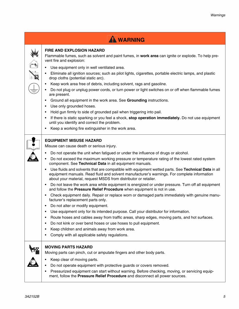
FIRE AND EXPLOSION HAZARDFlammable fumes, such as solvent and paint fumes, in work area can ignite or explode. To help pre-vent fire and explosion:
• Use equipment only in well ventilated area.• Eliminate all ignition sources; such as pilot lights, cigarettes, portable electric lamps, and plastic
drop cloths (potential static arc). • Keep work area free of debris, including solvent, rags and gasoline.• Do not plug or unplug power cords, or turn power or light switches on or off when flammable fumes
are present.• Ground all equipment in the work area. See Grounding instructions.• Use only grounded hoses.• Hold gun firmly to side of grounded pail when triggering into pail.• If there is static sparking or you feel a shock, stop operation immediately. Do not use equipment
until you identify and correct the problem.• Keep a working fire extinguisher in the work area.
EQUIPMENT MISUSE HAZARDMisuse can cause death or serious injury.
• Do not operate the unit when fatigued or under the influence of drugs or alcohol.• Do not exceed the maximum working pressure or temperature rating of the lowest rated system
component. See Technical Data in all equipment manuals.• Use fluids and solvents that are compatible with equipment wetted parts. See Technical Data in all
equipment manuals. Read fluid and solvent manufacturer’s warnings. For complete information about your material, request MSDS from distributor or retailer.
• Do not leave the work area while equipment is energized or under pressure. Turn off all equipment and follow the Pressure Relief Procedure when equipment is not in use.
• Check equipment daily. Repair or replace worn or damaged parts immediately with genuine manu-facturer’s replacement parts only.
• Do not alter or modify equipment.• Use equipment only for its intended purpose. Call your distributor for information.• Route hoses and cables away from traffic areas, sharp edges, moving parts, and hot surfaces.• Do not kink or over bend hoses or use hoses to pull equipment.• Keep children and animals away from work area.• Comply with all applicable safety regulations.
MOVING PARTS HAZARDMoving parts can pinch, cut or amputate fingers and other body parts.
• Keep clear of moving parts.• Do not operate equipment with protective guards or covers removed.• Pressurized equipment can start without warning. Before checking, moving, or servicing equip-
ment, follow the Pressure Relief Procedure and disconnect all power sources.
WARNING

Important Two-Component Material Information
6 3A2152B
Important Two-Component Material Information
Keep Components A (Red) and B (Blue) Separate
Changing Materials• When changing materials, flush the equipment mul-
tiple times to ensure it is thoroughly clean.
• Always clean the fluid inlet strainers after flushing.
• Check with your material manufacturer for chemical compatibility.
Cross-contamination can result in cured material in fluid lines which could cause serious injury or dam-age equipment. To prevent cross-contamination of the equipment’s wetted parts, never interchange component A (Red) and component B (Blue) parts.

Important Two-Component Material Information
3A2152B 7

Component Identification
8 3A2152B
Component Identification
FIG. 1: Machine Overview
ti18094a
A
ti18095a
ti18093a
H
D FB
K
LM
JN
G
E
C
P
Component Identification
3A2152B 9
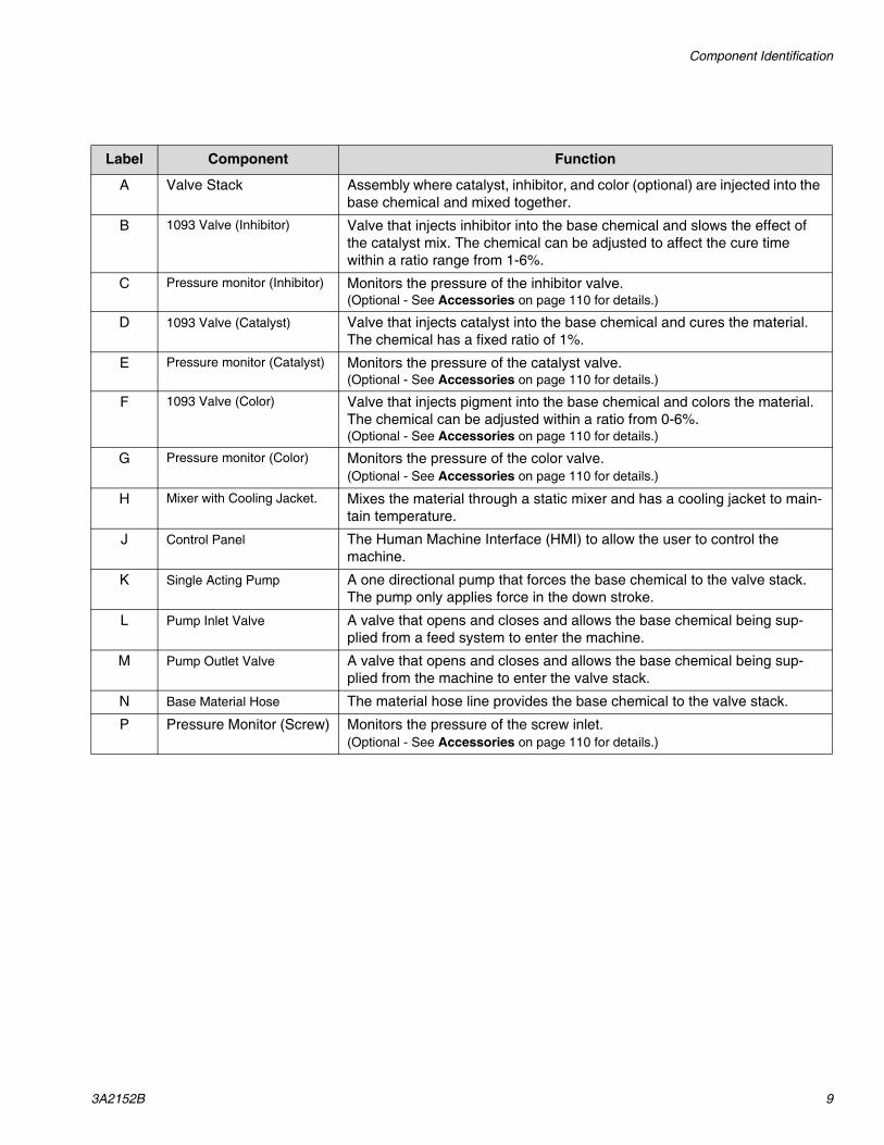
Label Component Function
A Valve Stack Assembly where catalyst, inhibitor, and color (optional) are injected into the base chemical and mixed together.
B 1093 Valve (Inhibitor) Valve that injects inhibitor into the base chemical and slows the effect of the catalyst mix. The chemical can be adjusted to affect the cure time within a ratio range from 1-6%.
C Pressure monitor (Inhibitor) Monitors the pressure of the inhibitor valve.(Optional - See Accessories on page 110 for details.)
D 1093 Valve (Catalyst) Valve that injects catalyst into the base chemical and cures the material. The chemical has a fixed ratio of 1%.
E Pressure monitor (Catalyst) Monitors the pressure of the catalyst valve.(Optional - See Accessories on page 110 for details.)
F 1093 Valve (Color) Valve that injects pigment into the base chemical and colors the material. The chemical can be adjusted within a ratio from 0-6%.(Optional - See Accessories on page 110 for details.)
G Pressure monitor (Color) Monitors the pressure of the color valve.(Optional - See Accessories on page 110 for details.)
H Mixer with Cooling Jacket. Mixes the material through a static mixer and has a cooling jacket to main-tain temperature.
J Control Panel The Human Machine Interface (HMI) to allow the user to control the machine.
K Single Acting Pump A one directional pump that forces the base chemical to the valve stack. The pump only applies force in the down stroke.
L Pump Inlet Valve A valve that opens and closes and allows the base chemical being sup-plied from a feed system to enter the machine.
M Pump Outlet Valve A valve that opens and closes and allows the base chemical being sup-plied from the machine to enter the valve stack.
N Base Material Hose The material hose line provides the base chemical to the valve stack.
P Pressure Monitor (Screw) Monitors the pressure of the screw inlet.(Optional - See Accessories on page 110 for details.)

Component Identification
10 3A2152B
FIG. 2: Electrical Panel
ti18096a
AA
ti18097a
AB
AE
AC
AF
AD
AG
Components are found within enclosure.
CB1CB2
FU-1FU-2
FU-6FU-7
FU-3FU-5
FU-9
FU-4FU-8
FU-10

Component Identification
3A2152B 11
Most circuit breakers are located inside the power distri-bution box. The main block of circuit breakers in the power distribution box is detailed below.
Label Component Function
AA Disconnect Turns the main power ON/OFF of the machine
AB HMI Machine controls. Allows the user to enter/read data
AC Ethernet Port Communication port to a PLC
AD Power ON/OFF Turns the power ON/OFF for the controls
AE E-Stop Emergency stop button to turn OFF power of the machine
AF Audio Alarm Alerts operator of a machine fault through sound
AG Foot Switch Signals machine to start cycle when pressed
Label Component Size (Amps) Type Used in Models
CB1 24 VDC Power 5 N/A All
CB2 PLC Power Supply 5 N/A All
FU-1 Drive Control Power 10 LPJ-10SP Bussman All
FU-2 Drive Control Power 10 LPJ-10SP Bussman All
FU-3 Drive Motor Power 20 KTK-R-20 Bussman All
FU-4 Drive Motor Power 20 KTK-R-20 Bussman All
FU-5 Drive Motor Power 20 KTK-R-20 Bussman All
FU-6 Drive Control Power 10 LPJ-10SP Bussman Kit 24M126
FU-7 Drive Control Power 10 LPJ-10SP Bussman Kit 24M126
FU-8 Drive Motor Power 20 KTK-R-20 Bussman Kit 24M126
FU-9 Drive Motor Power 20 KTK-R-20 Bussman Kit 24M126
FU-10 Drive Motor Power 20 KTK-R-20 Bussman Kit 24M126

Setup
12 3A2152B
SetupInitial Machine SetupPerform this setup procedure to prepare the machine for initial operation.
1. Locate the machine.
a. Locate the machine on a level surface and bolt to the floor. See Technical Data starting on page 108 for space requirements and mounting hole pattern.
b. Connect the valve stack to the screw inlet located on the press. External brackets may be required to support the stack. Install a valve between the mixer and the screw. The valve can be controlled by the LSR system. See Appendix D - Selecting the Outlet Valve, Mounting the Stack to the Press on page 107.
2. Connect the electrical cord.
Electrical Cord Requirements
NOTE: Power cord is not supplied. See the following table.
Electrical Cord Wires by Model
230V, 3 phase: L1, L2, L3, GND
a. Connect green wire to ground (GRN).
b. Use a screw driver to tighten the terminals to 12 in-lb (1.4 N•m)
The machine is not properly grounded until this setup procedure is performed. To prevent risk of electric shock, do not start the machine until this setup proce-dure is completed.
NOTICE
To prevent machine damage, do not expose system to rain.
FIG. 3: Valve Stack Outletti18098a
3/4” NPT Male
Installing this equipment requires access to parts which may cause electric shock or other serious injury if work is not performed properly. Have a qualified electrician connect power and ground to main power switch terminals. All electrical wiring must be done by a qualified electrician and comply with all local codes and regulations.
Table 1: Power Cord Requirements
ModelCord Requirements
AWG (mm2)
230V, 3 phase 8 (8.4), 3 wire + ground
FIG. 4: Electrical Disconnect
ti18099a
L1
L2
L3
GND

Setup
3A2152B 13
3. Ground the system.
a. Control enclosure and pump: grounded through power cord. See Connect the electrical cord. on page 12.
b. Valve stack: Follow your local code.
c. Fluid supply containers: Follow your local code.
d. Solvent pails used when flushing: follow your local code. Use only metal pails, which are con-ductive, placed on a grounded surface. Do not place pail on a nonconductive surface, such as paper or cardboard, which interrupts grounding continuity.
e. To maintain grounding continuity when flushing or relieving pressure, hold grounded metal pail firmly to a metal part of dispense valve then initi-ate a dispense.
4. Connect the press output signal to the customer input located in the panel.
Add customer signal from the press when the press is ready to load the screw by either:
a. Connecting a 24 VDC signal from the press to the relay CR-CS.
b. Connecting a dry contact signal across lines 8 and 6850 on the terminal assembly. Refer to Control Schematics, 24L890, page 76, for additional clarity.
This equipment must be grounded.
FIG. 5: Relay CR-CS
CR-CS
A1 A2
123386
CUSTOMER START
CONNECT 24VDC STARTSIGNAL FROM PRESS
Setup
14 3A2152B
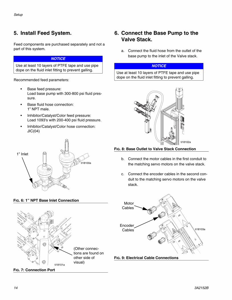
5. Install Feed System.
Feed components are purchased separately and not a part of this system.
Recommended feed parameters:
• Base feed pressure:Load base pump with 300-800 psi fluid pres-sure.
• Base fluid hose connection:1” NPT male.
• Inhibitor/Catalyst/Color feed pressure:Load 1093's with 200-400 psi fluid pressure.
• Inhibitor/Catalyst/Color hose connection:JIC(04)
6. Connect the Base Pump to the Valve Stack.
a. Connect the fluid hose from the outlet of the base pump to the inlet of the Valve stack.
b. Connect the motor cables in the first conduit to the matching servo motors on the valve stack.
c. Connect the encoder cables in the second con-duit to the matching servo motors on the valve stack.
NOTICE
Use at least 10 layers of PTFE tape and use pipe dope on the fluid inlet fitting to prevent galling.
FIG. 6: 1” NPT Base Inlet Connection
FIG. 7: Connection Port
ti18100a
1” Inlet
ti18101a
(Other connec-tions are found on other side of visual)
NOTICE
Use at least 10 layers of PTFE tape and use pipe dope on the fluid inlet fitting to prevent galling.
FIG. 8: Base Outlet to Valve Stack Connection
FIG. 9: Electrical Cable Connections
ti18102a
ti18103a
MotorCables
EncoderCables

Setup
3A2152B 15
d. Connect the sensor lines and solenoid lines in the third conduit to the matching valves on the valve stack.
e. If using kit 24M127, connect the pressure trans-ducer cables in the third conduit to the matching transducers on the valve stack.
f. Connect the ground wire in the sensor conduit to the screw holding the solenoid valves to the stack.
g. A set of clamps is supplied to keep the three sections of conduit together. This can be mounted on the press.
7. Connect the Air Supply.
a. Connect a 1/4” in. air supply to the solenoid valve inlet on the valve stack.
b. Connect a 1/4 in. air supply to the solenoid valve inlet on the base frame.
FIG. 10: Clamps
11.00
.50
11.50
ti18104a
NOTICETo prevent machine damage, air supply must be fil-tered and dried.
FIG. 11: Air Supply Connection - Valve Stack
FIG. 12: Air Supply Connection - Base
ti18105a
1/4” Air Supply
ti18106a
1/4” Air Supply

Setup
16 3A2152B
8. Connect chiller with 1/4” tubing.
9. Perform Startup procedure on page 17.
10.Perform Human Machine Interface (HMI) setup.
Refer to Appendix A - HMI Screens Overview starting on page 86 for more information.
a. Navigate to DRIVE/VALVE setup screen. Push the ENABLE drive button for each component to enable the drives.
b. If the drives have been unplugged, refer to Appendix C - Setting Home Position on Pumps starting page 105.
c. Verify the indicators read that each drive is HOME. If not, push the HOME PUMP push but-ton.
11.Perform Flushing Procedure start-ing on page 19.
12.Perform System Calibration Pro-cedure starting on page 23.
FIG. 13: Chiller Connections
ti18201a
Coolant In
Coolant Out
NOTICE
The machine is tested with oil at the factory. Flush out the oil with a compatible solvent before loading the machine with material.

Operation
3A2152B 17
Operation
Startup
1. Perform all required maintenance tasks. See Main-tenance starting on page 25.
2. Check for leaks.
3. Check feed system fluid levels.
4. Turn the main disconnect switch to the ON position. The HMI will start running through its startup proce-dure. This takes about a minute.
5. Push the power on button. The white pilot light will illuminate.
Shutdown
Short Term/End of shift
1. Verify the cooling jackets are on and the mixed material is being chilled. Keeping the mixed mate-rial cool will keep the material from curing as fast.
2. Perform Base Purge, page 19.
3. Perform Pressure Relief Procedure, page 18.
4. Turn the main disconnect switch to the “OFF” posi-tion.
Extended periods
1. Perform Base Purge, page 19.
2. Perform Pressure Relief Procedure, page 18.
3. Turn the main disconnect switch to the “OFF” posi-tion.
4. Remove the cooling jacket from the mixer.
5. Remove the mixer from the screw.
6. Remove the bottom block from the mixer stack.
7. Clean the mixer and bottom block with a compatible solvent.
NOTICE
To avoid curing the material within the mixer, do not run the catalyst without the inhibitor.
Operation
18 3A2152B
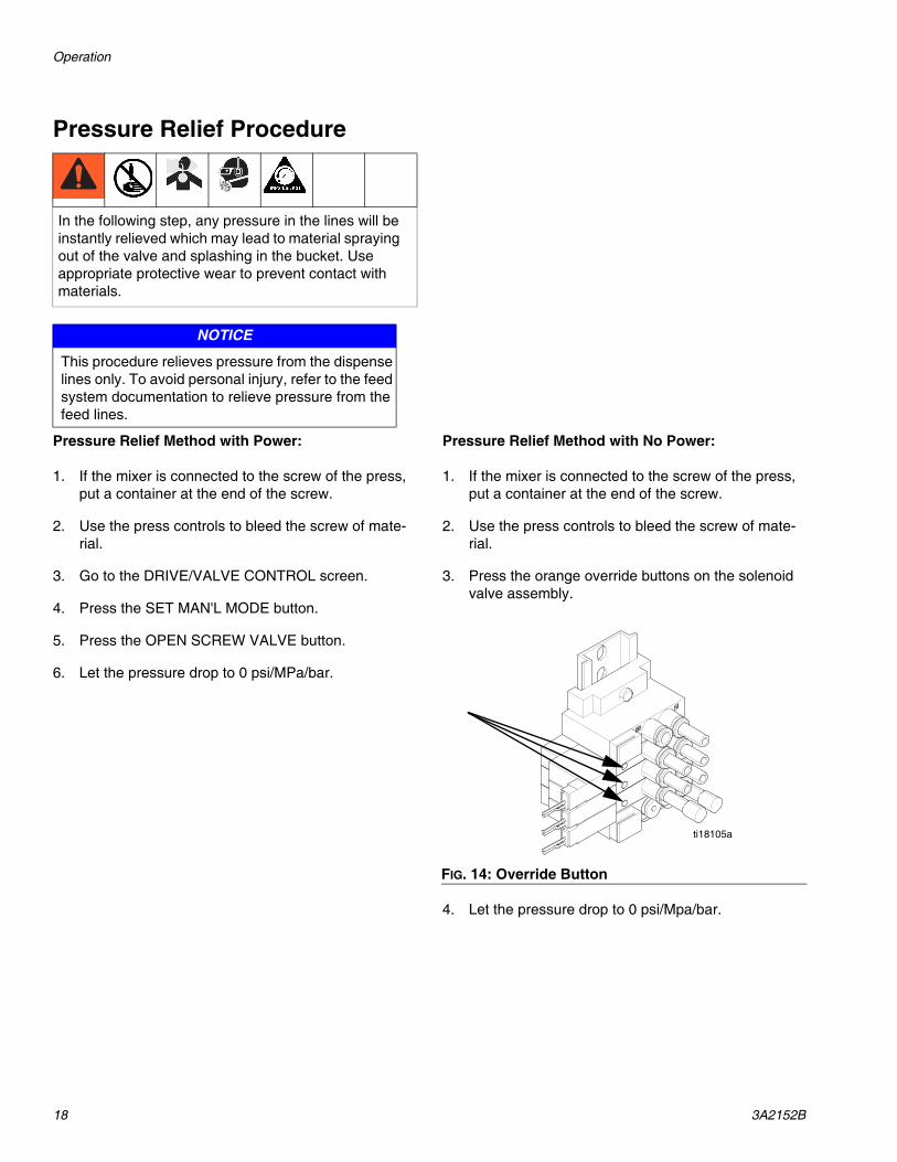
Pressure Relief Procedure
Pressure Relief Method with Power:
1. If the mixer is connected to the screw of the press, put a container at the end of the screw.
2. Use the press controls to bleed the screw of mate-rial.
3. Go to the DRIVE/VALVE CONTROL screen.
4. Press the SET MAN'L MODE button.
5. Press the OPEN SCREW VALVE button.
6. Let the pressure drop to 0 psi/MPa/bar.
Pressure Relief Method with No Power:
1. If the mixer is connected to the screw of the press, put a container at the end of the screw.
2. Use the press controls to bleed the screw of mate-rial.
3. Press the orange override buttons on the solenoid valve assembly.
4. Let the pressure drop to 0 psi/Mpa/bar.
In the following step, any pressure in the lines will be instantly relieved which may lead to material spraying out of the valve and splashing in the bucket. Use appropriate protective wear to prevent contact with materials.
NOTICE
This procedure relieves pressure from the dispense lines only. To avoid personal injury, refer to the feed system documentation to relieve pressure from the feed lines.
FIG. 14: Override Button
ti18105a

Operation
3A2152B 19
Base Purge
1. Navigate to the AUTO MODE SETUP SCREEN.
2. Set the CATALYST PERCENT OF MIX to zero.
3. Set the INHIBITOR PERCENT OF MIX to 6%.
4. Press the footswitch and take about fifteen shots to get the existing catalyst out of the mixer.
5. Verify the mix will not cure by wiping a small amount of mixed material from the last shot on the heated mold in the press and seeing if the material cures.
6. If the material cures, take some more shots, testing the material until the material does not cure.
To start dispensing again after a base purge, go to the AUTO MODE SETUP screen, set the catalyst back to 1% and begin dispensing. After the same amount of shots that took to base purge, material with catalyst should begin to dispense through the mixer. To verify this, wipe a small amount of mixed material from the last shot on the heated mold in the press and see if the material cures.
Flushing Procedure
Flush out old fluid with new fluid or flush out old fluid with a compatible solvent before introducing a new fluid. All fluid components are compatible with common sol-vents. Use only moisture-free solvents. See Technical Data on page 108 for a list of wetted components to ver-ify compatibility of solvent with wetted materials. See solvent manufacturer's information for material compati-bility. Do not use water.
Ground the solvent pails used when flushing: Refer to Ground the system. on page 13.
If flushing with a compatible solvent, perform the follow-ing procedure:
1. Perform Shutdown, page 17.
2. Disconnect the valve stack from the screw located on the press.
3. Disconnect the base pump inlet from the feed pump.
4. Connect the flushing hose into the base pump inlet.
5. Perform Startup, page 17.
6. Navigate to the DRIVE/VALVE CONTROL screen.
7. Press the SET IN MAN'L MODE button to put the system in manual mode.
8. Push the base OPEN INLET VALVE, OPEN OUT-LET VALVE, and OPEN SCREW VALVE buttons so there is a clear path to flush.
9. Start flushing.
10. When the silicone is no longer dispensing from the mixer, stop flushing.
NOTE: Even though flushing will get the majority of the material out of the stack and mixer, disassemble the blocks and mixer and clean these parts individually.
NOTICE
Mixed material with start to gel in the mixer if the machine is idle for a prolonged periods of time, causing machine damage. Perform a base purge as required.
Flush equipment only in a well-ventilated area. Do not dispense flammable fluids. Do not turn on heaters while flushing with flammable solvents.

Operation
20 3A2152B
Priming
Overview: Prime the base, add the inhibitor, and then add the catalyst. This assumes all feed system pumps are loaded, primed and ready to dispense.
NOTE: Prime with the valve stack not connected up to the screw located on the press.
1. Disconnect the mixer and valve stack from the screw located on the press.
2. Place a waste container under the mixer.
3. Prime the base component.
a. Go to the DRIVE/VALVE CONTROL Screen.
b. ENABLE the base drive.
c. HOME the base drive.
d. In the ALL window, press the SET MAN'L MODE button.
e. When the Base indicates the pump is HOME, press the EXTEND PUMP button and wait for the base pump to fully extend.
f. Push the OPEN INLET VALVE button and verify the indicator shows OPEN.
g. Push the OPEN OUTLET VALVE button and verify the indicator shows OPEN.
h. If a customer supplied valve is installed between the mixer and screw, push the OPEN SCREW VALVE button and verify the screen shows OPEN.
i. When all valves are open and there is a clear path from the inlet valve to the mixer, slowly increase the air pressure on the feed pump until the feed pump begins to cycle.
j. Let the feed pump cycle until air free base mate-rial comes out the end of the mixer.
k. Press the CLOSE OUTLET VALVE push button and verify the Indicator shows CLOSED.
l. Press the CLOSE SCREW VALVE push button and verify the indicator shows CLOSED.
m. Press the HOME PUMP push button. The actu-ator shaft will rise and the feed pump will cycle to charge the pump.
n. Adjust the feed pump air pressure so the base material pressure shows approximately 500 psi (3.4 MPa, 34 bar). The pressure read-out shows on either the STARTUP, STATUS, or PRESSURE LOG screens.
4. Prime the inhibitor pump (1093 valve).
a. Turn the air pressure on the inhibitor feed pump so that the actual material pressure is around 300 psi (2.1 MPa, 21 bar). This is an estimate based on the air pressure on the feed pump and the power factor of the pump. If pressure trans-ducers are included (kit 24M127), the inhibitor pressure readout can be seen on either the STARTUP, STATUS, or PRESSURE LOG screens.
b. On the DRIVE/VALVE CONTROL screen, push the SET AUTO MODE button.
c. If a customer supplied screw valve is being used, push the AUTO SCREW VALVE push button.
d. Verify all pumps are ENABLED and HOME.
e. Go to the AUTO MODE SETUP screen.
f. Set the TOTAL FLOW RATE to 4-6cc/sec.
g. Set the INHIBITOR PERCENT OF MIX to 6%
h. Set the CATALYST PERCENT OF MIX to zero.
i. If color is used (Kit 24M126), Set the COLOR PERCENT OF MIX to zero.

Operation
3A2152B 21
j. Verify the BASE PERCENT OF MIX is 94% and the TOTAL PERCENT (REF) is 100%
k. Press and hold the footswitch down. The base pump and inhibitor pump (1093 valve) will start to dispense.
l. When the base pump hits the end travel, release the footswitch; both pumps will reload.
m. When the pumps are reloaded, repeat this about fifteen times to verify the volume of the mixer has inhibitor through the mixer and the material coming out is air-free.
5. Prime the catalyst pump (1093 valve).
a. Turn the air pressure on the catalyst feed pump so that the actual material pressure is around 300 psi (2.1 MPa, 21 bar). This is an estimate based on the air pressure on the feed pump and the power factor of the pump. If pressure trans-ducers are included (kit 24M127), the catalyst pressure readout can be seen on either the STARTUP, STATUS, or PRESSURE LOG screen.
b. On the DRIVE/VALVE CONTROL screen, push the SET AUTO MODE button.
c. If a customer supplied screw valve is being used, push the AUTO SCREW VALVE push button.
d. Verify all pumps are ENABLED and HOME.
e. Go to the AUTO MODE SETUP screen.
f. Set the TOTAL FLOW RATE to 4-6cc/sec.
g. Set the INHIBITOR PERCENT OF MIX to 6%
h. Set the CATALYST PERCENT OF MIX to 1%.
i. If color is used (Kit 24M126), Set the COLOR PERCENT OF MIX to zero.
j. Verify the BASE PERCENT OF MIX is 93% and the TOTAL PERCENT (REF) is 100%
k. Press and hold the footswitch down. The base pump, inhibitor, and catalyst pump (1093 valve) will start to dispense.
l. When the base pump hits the end travel, release the footswitch; all pumps will reload.
m. When the pumps are reloaded, repeat this about fifteen times to verify the volume of the mixer has catalyst through the mixer and the material coming out is air-free.
6. Prime the color pump (1093 valve). Valid only if kit 24M126 is being used.
a. Turn the air pressure on the color feed pump so that the actual material pressure is around 300 psi (2.1 MPa, 21 bar). This is an estimate based on the air pressure on the feed pump and the power factor of the pump. If pressure trans-ducers are included (kit 24M128), the color pressure readout can be seen on either the STARTUP, STATUS, or PRESSURE LOG screens.
b. On the DRIVE /VALVE CONTROL screen, push the SET AUTO MODE button.
c. If a customer supplied screw valve is being used, push the AUTO SCREW VALVE push button.
d. Verify all pumps are ENABLED and HOME.
e. Go to the AUTO MODE SETUP screen.
f. Set the TOTAL FLOW RATE to 4-6cc/sec.
NOTICE
After the catalyst has been added, the material is able to cure. To avoid machine damage from long idle times, perform a Base Purge, page 19.
NOTICE
After the catalyst has been added, the material is able to cure. To avoid machine damage from long idle times, perform a Base Purge, page 19.

Operation
22 3A2152B
g. Set the INHIBITOR PERCENT OF MIX to 6%.
h. Set the CATALYST PERCENT OF MIX to 0% or 1%.
i. Set the COLOR PERCENT OF MIX to the desired percent.
j. Verify the TOTAL PERCENT (REF) is 100%
k. Press and hold the footswitch down. All pumps will start to dispense.
l. When the base pump hits the end travel released the footswitch; all pumps will reload.
m. When the pumps are reloaded, repeat this about fifteen times to verify the volume of the mixer has color through the mixer and the mate-rial coming out is air-free.
Operation
3A2152B 23
System Calibration Procedure
Perform this entire procedure if any of the following con-ditions are met:
• The machine is new.• The materials in the system have been
changed.
Software Settings:
1. Go to the AUTO MODE SETUP screen.
2. Enter the flow rate and ratio percentages.
3. Go to the DRIVE/VALVE SETUP screen.
4. ENABLE ALL the drives.
5. HOME the pumps of they are not home.
Prime the Machine:
1. Press the footswitch or give a maintained signal from the press to begin pumping.
2. After dispensing close to a full shot, release the footswitch or signal from the press and let the pumps reload.
3. Repeat this until air-free material is dispensed.
4. Repeat around fifteen more times to ensure the new mix of material has traveled through the mixer.
5. Connect the mixer to the customer supplied screw inlet valve.
6. Repeat more shots until air free material is dis-pensed out of the screw.
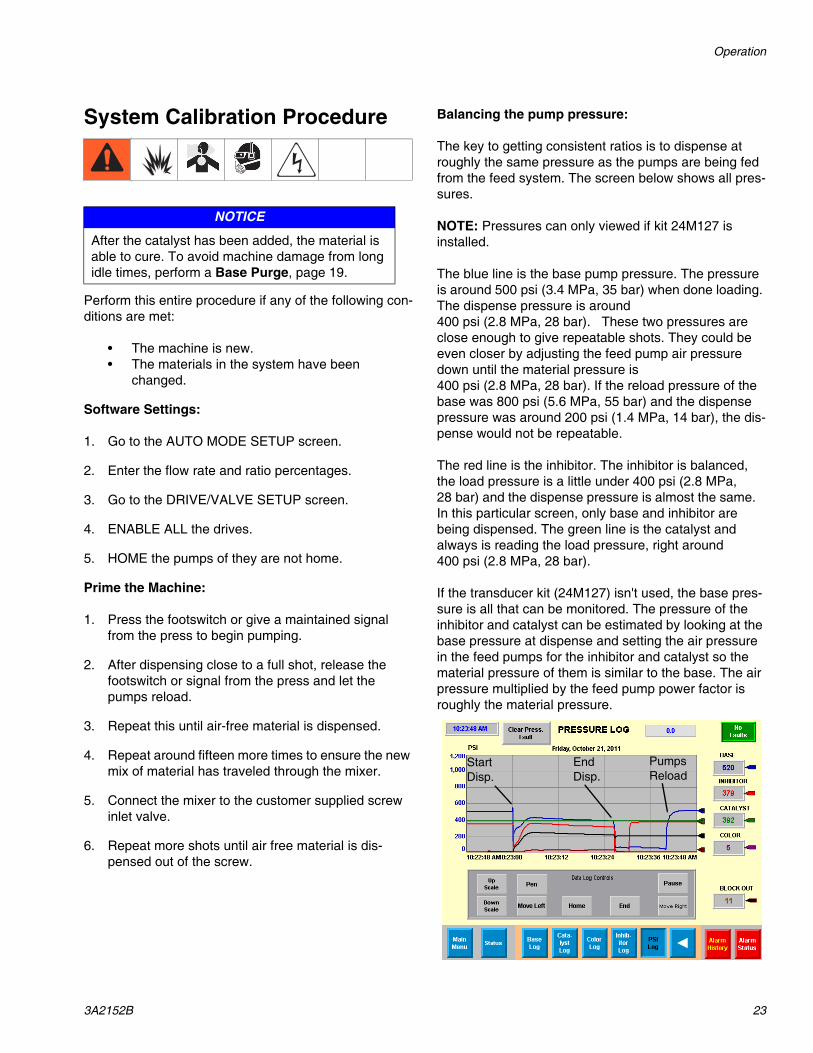
Balancing the pump pressure:
The key to getting consistent ratios is to dispense at roughly the same pressure as the pumps are being fed from the feed system. The screen below shows all pres-sures.
NOTE: Pressures can only viewed if kit 24M127 is installed.
The blue line is the base pump pressure. The pressure is around 500 psi (3.4 MPa, 35 bar) when done loading. The dispense pressure is around 400 psi (2.8 MPa, 28 bar). These two pressures are close enough to give repeatable shots. They could be even closer by adjusting the feed pump air pressure down until the material pressure is 400 psi (2.8 MPa, 28 bar). If the reload pressure of the base was 800 psi (5.6 MPa, 55 bar) and the dispense pressure was around 200 psi (1.4 MPa, 14 bar), the dis-pense would not be repeatable.
The red line is the inhibitor. The inhibitor is balanced, the load pressure is a little under 400 psi (2.8 MPa, 28 bar) and the dispense pressure is almost the same. In this particular screen, only base and inhibitor are being dispensed. The green line is the catalyst and always is reading the load pressure, right around 400 psi (2.8 MPa, 28 bar).
If the transducer kit (24M127) isn't used, the base pres-sure is all that can be monitored. The pressure of the inhibitor and catalyst can be estimated by looking at the base pressure at dispense and setting the air pressure in the feed pumps for the inhibitor and catalyst so the material pressure of them is similar to the base. The air pressure multiplied by the feed pump power factor is roughly the material pressure.
NOTICE
After the catalyst has been added, the material is able to cure. To avoid machine damage from long idle times, perform a Base Purge, page 19.
StartDisp.
EndDisp.
PumpsReload

Operation
24 3A2152B
DispensingAfter the pressures are balanced and the system is dis-pensing air free material, the mixer is ready to connect to the screw inlet located on the press. The mixer outlet is 1” NPT. Continue priming through the screw.
Determining the flow rate:
Once the mixer is connected to the screw, the flow rate needs to be adjusted so the flow rate does not fill the screw too fast or too slow. See the charts below show-ing only the mixer pressure.
If the kit for the transducers isn't used, a gauge at the screw inlet will give an indication of the pressure rise or fall while dispensing.
Maintenance
3A2152B 25
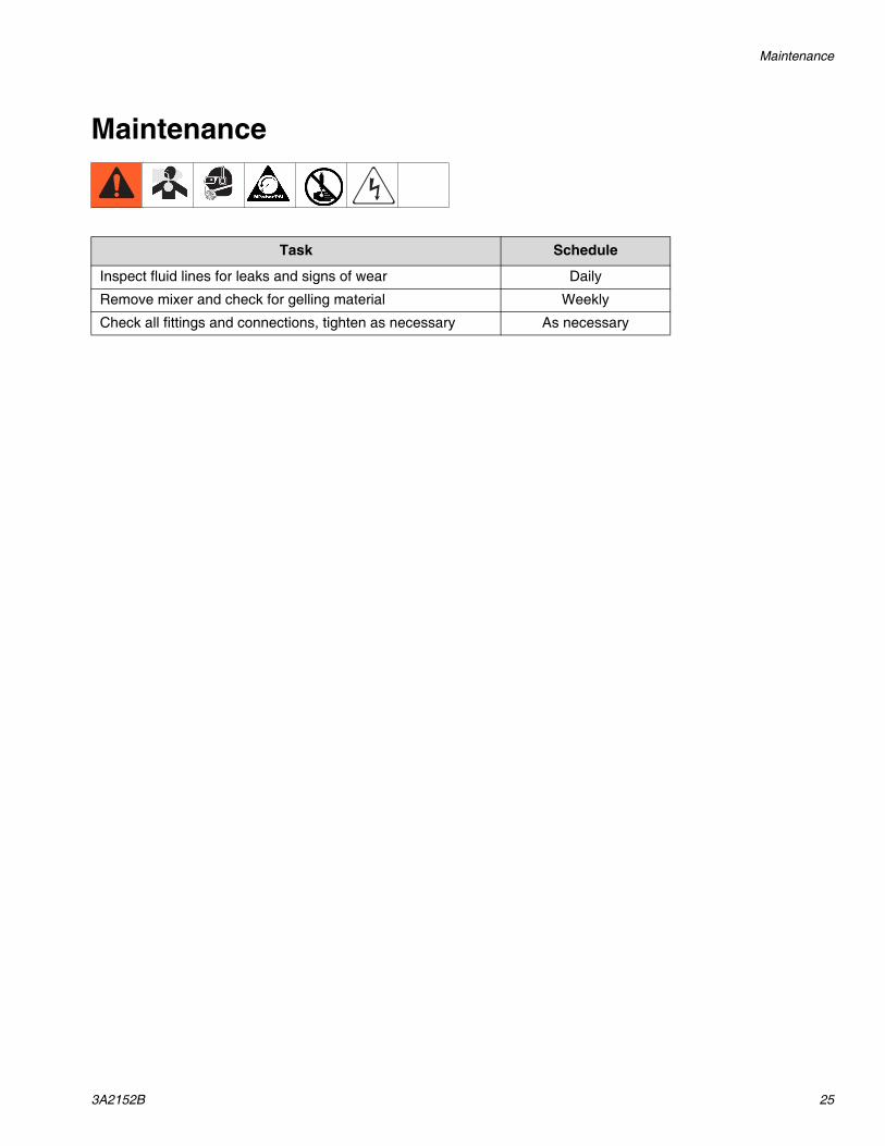
Maintenance
Task Schedule
Inspect fluid lines for leaks and signs of wear Daily
Remove mixer and check for gelling material Weekly
Check all fittings and connections, tighten as necessary As necessary
Troubleshooting
26 3A2152B
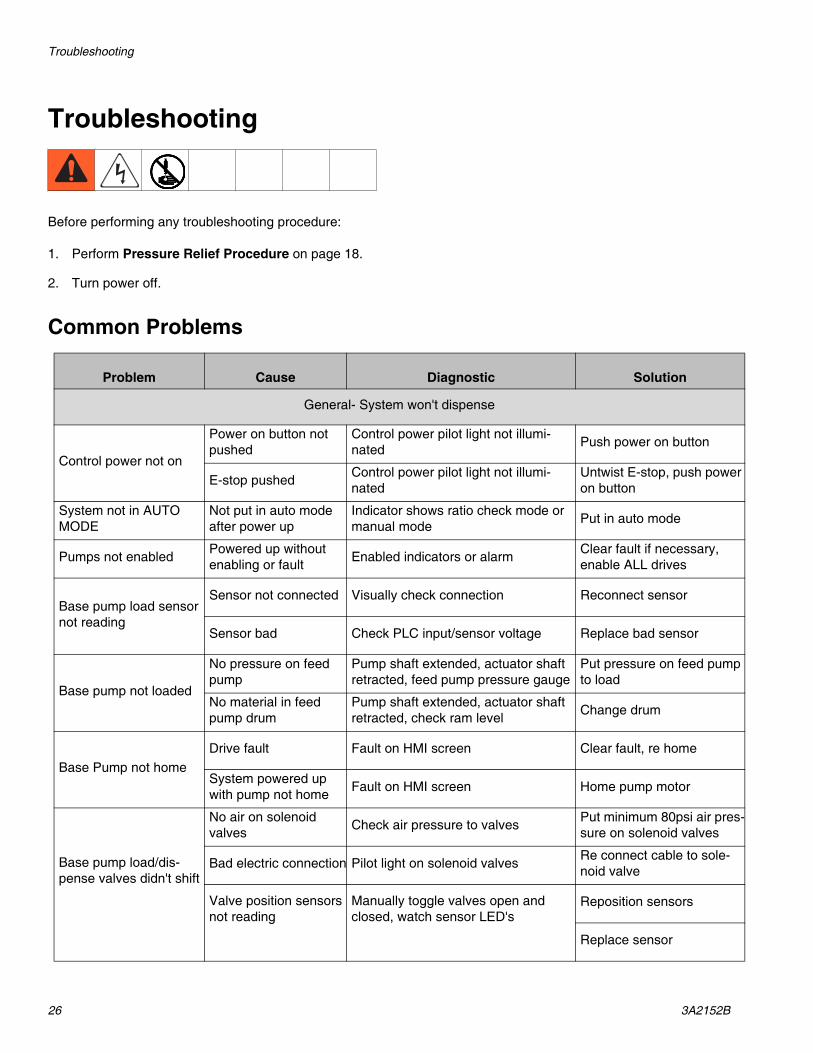
Troubleshooting
Before performing any troubleshooting procedure:
1. Perform Pressure Relief Procedure on page 18.
2. Turn power off.
Common Problems
Problem Cause Diagnostic Solution
General- System won't dispense
Control power not on
Power on button not pushed
Control power pilot light not illumi-nated Push power on button
E-stop pushed Control power pilot light not illumi-nated
Untwist E-stop, push power on button
System not in AUTO MODE
Not put in auto mode after power up
Indicator shows ratio check mode or manual mode Put in auto mode
Pumps not enabled Powered up without enabling or fault Enabled indicators or alarm Clear fault if necessary,
enable ALL drives
Base pump load sensor not reading
Sensor not connected Visually check connection Reconnect sensor
Sensor bad Check PLC input/sensor voltage Replace bad sensor
Base pump not loaded
No pressure on feed pump
Pump shaft extended, actuator shaft retracted, feed pump pressure gauge
Put pressure on feed pump to load
No material in feed pump drum
Pump shaft extended, actuator shaft retracted, check ram level Change drum
Base Pump not homeDrive fault Fault on HMI screen Clear fault, re home
System powered up with pump not home Fault on HMI screen Home pump motor
Base pump load/dis-pense valves didn't shift
No air on solenoid valves Check air pressure to valves Put minimum 80psi air pres-
sure on solenoid valves
Bad electric connection Pilot light on solenoid valves Re connect cable to sole-noid valve
Valve position sensors not reading
Manually toggle valves open and closed, watch sensor LED's
Reposition sensors
Replace sensor

Troubleshooting
3A2152B 27
Inh/Cat pump load/dis-pense sensor not work-ing
Bad connection Visually check connection Reconnect sensor
Bad sensor Check PLC input/sensor voltage Replace bad sensor
Inh/Cat Pump not homeDrive fault Fault on HMI screen Clear fault, re home
System powered up with pump not home Fault on HMI screen Home pump motor
Inh/Cat pump load/dis-pense valves didn't shift
No air on solenoid valves Check air pressure to valves Put minimum 80psi air pres-
sure on solenoid valves
Bad electric connection Pilot light on solenoid valves Reconnect cable to sole-noid valve
Mixer plugged Mixed material cured Very high pressure Tear down and clean out mixer/stack assembly
Customer supplied screw valve not opening
Air lines to valve back-wards Very high pressure Check air connections,
swap if necessary
Valve cured up Very high pressure Tear down and clean out screw valve
General- Mixed material won't cure
Catalyst not being added
Catalyst percentage not set to 1% Verify HMI Set to 1%
Broken lead screw nut Motor turns but no linear movement Replace lead screw nut
Catalyst added is no good
Contaminated with moisture from air Catalyst is yellow, not clear Replace catalyst
General- Mixed material cures too fast or cures even when base purging
Catalyst still being added
Catalyst percentage still set at 1% Verify HMI Set to zero percent
Bad seal on catalyst non drip valve
Pull catalyst valve out of stack and inspect
Replace non drip valve seat.
Inhibitor not being added
Inhibitor percentage set to zero or not high enough
Verify HMI Increase inhibitor percent-age
Broken lead screw nut Motor turns but no linear movement Replace lead screw nut
Problem Cause Diagnostic Solution

Troubleshooting
28 3A2152B
Machine AlarmsThe following is a list of possible alarms.
# DESCRIPTION TYPE CAUSE SOLUTION1 INPUT POWER OFF FAULT Alarm N/A N/A
2 CONTROL POWER OFF FAULT Alarm Power on button not pressed/Estop pressed Push power on button
3 24VDC POWER OFF FAULT Alarm N/A N/A
4 BASE PUMP OVERTRAVEL Shutdown
Pump is extended too far in either direction
Get pump back within travel limits
5 INHIBITOR PUMP OVERTRAVEL Shutdown
6 CATALYST PUMP OVERTRAVEL Shutdown
7 COLOR PUMP OVERTRAVEL Shutdown
8 BASE PUMP OVER CURRENT Shutdown
Motor or transmission malfunction
Check/replace motor or transmission
9 INHIBITOR PUMP OVER CURRENT Shutdown
10 CATALYST PUMP OVER CURRENT Shutdown
11 COLOR PUMP OVER CURRENT Shutdown
12 BASE DRIVE OVER TEMP Shutdown
Excessive heat exists in the power circuitry
Reduce duty cycle, check for clogged vents, defective fan
13 INHIBITOR DRIVE OVER TEMP Shutdown
14 CATALYST DRIVE OVER TEMP Shutdown
15 COLOR DRIVE OVER TEMP Shutdown
16 BASE MOTOR OVER TEMP ShutdownHigh ambient motor temperature and/or excessive current
Operate within continuous torque rating for ambient temperature maximum
17 INHIBITOR MOTOR OVER TEMP Shutdown
18 CATALYST MOTOR OVER TEMP Shutdown
19 COLOR MOTOR OVER TEMP Shutdown
20 BASE DRIVE FEEDBACK ERROR ShutdownFeedback wiring is open, shorted, or miss-ing
Check motor encoder wiring.21 INHIBITOR DRIVE FEEDBACK ERROR Shutdown
22 CATALYST DRIVE FEEDBACK ERROR Shutdown
23 COLOR DRIVE FEEDBACK ERROR Shutdown
24 BASE DRIVE OVERLOAD Shutdown
Load limit of motor/drive has been exceeded Check for blocked fluid path
25 INHIBITOR DRIVE OVERLOAD Shutdown
26 CATALYST DRIVE OVERLOAD Shutdown
27 COLOR DRIVE OVERLOAD Shutdown
28 BASE MOTOR POSITION ERROR Shutdown
Position error limit was exceeded Check for blocked fluid path
29 INHIBITOR MOTOR POSITION ERROR Shutdown
30 CATALYST MOTOR POSITION ERROR Shutdown
31 COLOR MOTOR POSITION ERROR Shutdown
32 BASE RATIO CHECK SHOT OUT OF RANGE Alarm
Shot size entered too large or small
Change shot size within lim-its
33 INHIBITOR RATIO CHECK SHOT OUT OF RANGE Alarm
34 CATALYST RATIO CHECK SHOT OUT OF RANGE Alarm
35 COLOR RATIO CHECK SHOT OUT OF RANGE Alarm
36 BASE AXIS FAULT Shutdown
Drive has faulted Check drive diagnostic win-dow
37 INHIBITOR AXIS FAULT Shutdown
38 CATALYST AXIS FAULT Shutdown
39 COLOR AXIS FAULT Shutdown

Troubleshooting
3A2152B 29
40 BASE PRESSURE HIGH LIMIT Shutdown Fluid path blocked, flow rate too high
Check for blocked fluid path, lower flow rate
41 BASE PRESSURE LOW LIMIT Shutdown Pump not running, no material being fed
Check pump, check material level
42 INHIBITOR PRESSURE HIGH LIMIT Shutdown Fluid path blocked, flow rate too high
Check for blocked fluid path, lower flow rate
43 INHIBITOR PRESSURE LOW LIMIT Shutdown Pump not running, no material being fed
Check pump, check material level
44 CATALYST PRESSURE HIGH LIMIT Shutdown Fluid path blocked, flow rate too high
Check for blocked fluid path, lower flow rate
45 CATALYST PRESSURE LOW LIMIT Shutdown Pump not running, no material being fed
Check pump, check material level
46 COLOR PRESSURE HIGH LIMIT Shutdown Fluid path blocked, flow rate too high
Check for blocked fluid path, lower flow rate
47 COLOR PRESSURE LOW LIMIT Shutdown Pump not running, no material being fed
Check pump, check material level
48 SCREW PRESSURE HIGH LIMIT Shutdown Fluid path blocked, flow rate too high
Check for blocked fluid path, lower flow rate
49 SCREW PRESSURE LOW LIMIT Shutdown Fluid not being dis-pensed Check pumps
50 PRESSURE SHUTDOWN ALARM Alarm Any pressure out of spec
Check pump with pressure fault
51 BASE LOAD VALVE OPEN FAULT Alarm Valve not shifting to open position
Check/replace bad sensor, Check/correct air pressure, valve stuck
52 BASE LOAD VALVE CLOSE FAULT Alarm Valve not shifting to closed position
53 BASE DISPENSE VALVE OPEN FAULT Alarm Valve not shifting to open position
54 BASE DISPENSE VALVE CLOSE FAULT Alarm Valve not shifting to closed position
55 INHIBITOR VALVE SHIFT DISPENSE FAULT Alarm Spool valve not shifting to open position
56 INHIBITOR VALVE SHIFT LOAD FAULT Alarm Spool valve not shifting to closed position
57 CATALYST VALVE SHIFT DISPENSE FAULT Alarm Spool valve not shifting to open position
58 CATALYST VALVE SHIFTLOAD FAULT Alarm Spool valve not shifting to closed position
59 COLOR VALVE SHIFT DISPENSE FAULT Alarm Spool valve not shifting to open position
60 COLOR VALVE SHIFT LOAD FAULT Alarm Spool valve not shifting to closed position
# DESCRIPTION TYPE CAUSE SOLUTION

Troubleshooting
30 3A2152B
Drive FaultsThe drives have a diagnostic window that should have a “4” when everything is normal.
If a drive has a problem, a series of numbers flash in this window. Below is a list of error codes.
Error Code
Fault Message RSLogix (HIM) Problem or Symptom Potential Cause Possible Resolution
General Power (PWR) indicator not ON
No ac power or auxiliary logic power.
Verify ac control power is applied to the Kinetix 2000 system.
Internal power supply malfunction.
Call your Rockwell Automa-tion sales representative to return module for repair.
Motor jumps when first enabled
Motor wiring error. • Check motor wiring.• Run Hookup test in RSLogix 5000 software.
Incorrect motor chosen. Verify the proper motor is selected.
Digital I/O not working correctly
I/O power supply discon-nected.
Verify connections and I/O power source.
E00 BusUndervoltage Fault (Blown fuse)
A blown fuse was detected on the inverter PCB
Blown fuse. Call your Rockwell Automa-tion sales representative to return module for repair.
ti18126a

Troubleshooting
3A2152B 31
E04 Motor Overtemp Fault (Motor Overtemp)
Motor thermal switch tripped
High ambient motor tem-perature and/or exces-sive current
• Operate within (not above) the continuous torque rating for the ambient temperature 40 °C (104 °F) maximum.• Lower ambient temperature, increase motor cooling.
Motor wiring error. Check motor wiring at MF connector on the IAM/AM.
Incorrect motor selec-tion.
Verify the proper motor has been selected.
E05 Drive Overcurrent Fault (Power Fault)
Self-protection of the Intelligent Power Mod-ule (IPM) is indicating a major power related fault condition
Motor cables shorted. Verify continuity of motor power cable and connector.
Motor winding shorted internally.
Disconnect motor power cables from the motor. If the motor is difficult to turn by hand, it may need to be replaced.
Kinetix 2000 drive tem-perature too high.
• Check for clogged vents or defective fan.• Make sure cooling is not restricted by insufficient space around the unit.
Operation above contin-uous power rating and/or product environmental ratings.
• Verify ambient temperature is not too high.• Operate within the continuous power rating.• Reduce acceleration rates.
Kinetix 2000drive has a short circuit, overcur-rent, or failed compo-nent.
Remove all power and motor connections, and preform a continuity check from the dc bus to the U, V, and W motor outputs. If a continuity exists, check for wire fibers between terminals, or send drive in for repair.
E06 HardOvertravel Fault (+/- Hard Overtravel)
Axis moved beyond the physical travel limits in the positive/negative direction
Dedicated overtravel input is inactive.
• Check wiring.• Verify motion profile.• Verify axis configuration in soft-ware.
E07 MotFeedbackFault (Motor Feedback Loss)
The feedback wiring is open, shorted, or miss-ing.
• Check motor encoder wiring.• Run Hookup test in RSLogix 5000 software.
Error Code
Fault Message RSLogix (HIM) Problem or Symptom Potential Cause Possible Resolution

Troubleshooting
32 3A2152B
E09 BusUndervoltage Fault (Bus Undervolt-age)
With three-phase power present, the dc bus volt-age is below its limit
DC bus voltage for 230V system is below 137V
• Verify voltage level of the incoming ac power.• Check ac power source for glitches or line drop.• Install an uninterruptible power supply (UPS) on your ac input.
DC bus voltage fell below the undervoltage limit while an axis on the follower power rail was enabled
Disable follower axis before removing power.
E10 DriveOvervoltage Fault (Bus Overvolt-age)
The dc bus voltage is above its limit
Excessive regeneration of power. When the motor is driven by an external mechanical power source, it may regenerate too much peak energy through the drive power supply. The system faults to save itself from an overload.
• Change the deceleration or motion profile. • Use a larger sys-tem (motor and Kinetix 2000 drive). • Install shunt module.
DC bus voltage for 230V system is over 410V
Verify input is within specifica-tions.
E11 MotFeedbackFault (Illegal Hall State)
State of Hall feedback inputs is incorrect
Bad connections. • Verify the Hall wiring at the MF connector on the IAM/AM.• Verify 5V power supply to the encoder.
E16 Softovertravel Fault (+/- Software Over-travel)
Axis position exceeded maximum software setting. • Verify motion profile.• Verify overtravel settings are appropriate.
E18 OverSpeedFault (Overspeed Fault)
Motor speed has exceeded 150% of maximum rated speed. The 100% trip point is dictated by the lesser of the user velocity limits or the motor rated base speed.
• Check cables for noise.• Check tuning.
E19 PositionErrorFault (Follow Error)
Position error limit was exceeded. • Increase the feed forward gain.• Increase following error limit or time.• Check position loop tuning.• Verify sizing of system.• Verify mechanical integrity of system within specification limits.
E20 MotFeedbackFault (Mtr Fdbk AQB)
Motor Encoder State Error
The motor encoder encountered an illegal transition.
• Use shielded cables with twisted pair wires.• Route the feedback away from potential noise sources.• Check the system grounds.• Replace the motor/encoder.
E21 AuxFeedbackFault (Aux Feedback Comm)
Communication was not established with an intelli-gent encoder.
Verify auxiliary encoder wir-ing.
E30 MotFeedbackFault (Motor Feedback Comm)
Communication was not established with an intelli-gent encoder.
• Verify motor selection.• Verify the motor supports auto-matic identification.• Verify motor encoder wiring.
Error Code
Fault Message RSLogix (HIM) Problem or Symptom Potential Cause Possible Resolution

Troubleshooting
3A2152B 33
E34 GroundShortFault (Ground Fault)
Excessive ground cur-rent in the converter was detected
Wiring error. • Check motor power wiring.• Check input power wiring.
Motor internal ground short.
Replace motor.
Internal malfunction. Disconnect motor power cable from drive and enable drive with current limit set to 0. If fault clears, then a wiring error or motor internal problem exists. If fault remains, call your sales representative.
Grounded control power terminal (applies to 230V systems only).
• Remove ground from control power input.• Source control power from three-phase input power. Refer to the Power Wiring Examples on page 169 for more information.• Add isolation transformer for control power.
E35 DriveUndervoltage Fault (Pre-charge Fault)
Converter pre-charge cycle failed
Low AC input voltage. Check input ac voltage on all phases.
Internal malfunction. Call your sales representative. E36 DriveOvertemp Fault
(System Overtempera-ture)
Converter thermal switch tripped
Excessive heat exists in the power circuitry.
• Reduce acceleration rates.• Reduce duty cycle (ON/OFF) of commanded motion.• Increase time permitted for motion.• Use larger Kinetix 2000 con-verter.• Check for clogged vents or defective fan.• Make sure cooling is not restricted by insufficient space around the unit.
E37 PowerPhaseLoss Fault (Phase Loss Flt)
• One or more phases of the input ac power is missing.• Axis was enabled when main (three-phase) power was removed.• Common bus follower axis was enabled when dc bus power was removed.
• Check input ac voltage on all phases.• Disable axis before removing power.
E38 SERCOSFault (SER-COS Ring Flt)
The SERCOS ring is not active after being active and operational
Cable disconnected. Check that fiber-optic cable is present and connected prop-erly.
E39 DriveHardFault (Self Sense Flt)
Self-sensing Commuta-tion Startup Error
Motion required for self-sensing startup com-mutation was obstructed.
• Verify that there are no impedi-ments to motion at startup, such as hard limits.• Increase self-sensing current if high friction or load conditions exist.• Check motor or encoder wiring using wiring diagnostics.
Error Code
Fault Message RSLogix (HIM) Problem or Symptom Potential Cause Possible Resolution

Troubleshooting
34 3A2152B
E43 DriveEnableInput Fault (Drive Enable Flt)
Missing Drive Enable Input Signal
• An attempt was made to enable the axis through software while the Drive Enable hardware input was inactive.• The Drive Enable input transitioned from active to inactive while the axis was enabled.
• Disable the Drive Enable Input fault.• Verify that Drive Enable hard-ware input is active whenever the drive is enabled through software.
E50 SERCOSFault (SER-COS Same ADDR)
Duplicate node address detected on SERCOS ring. Verify that each SERCOS drive is assigned a unique node address.
E54 DriveHardFault (Ifbk HW Fault)
Current feedback hardware fault detected. Replace the module.
E60 DriveHardFault (Unknown Axis)
Illegal ID bits detected. Replace the module.
E61 AuxFeedbackFault (Aux Fdbk AQB)
Auxiliary Encoder State Error
The auxiliary encoder encountered an illegal transition.
• Use shielded cables with twisted pair wires.• Route the feedback away from potential noise sources.• Check the system grounds.• Replace the motor/encoder.
E62 AuxFeedbackFault (Aux Fdbk Loss)
The feedback wiring is open, shorted, or missing. Check the motor feedback cable connectors/wiring to the IAM/AM and motor.
E63 AuxFeedbackNoise (Aux Fdbk Noise)
Noise on auxiliary feed-back cable
Recommended ground-ing, per installation instructions, has not been followed.
• Verify grounding.• Route feedback cable away from noise sources.• Refer to System Design for Con-trol of Electrical Noise Reference Manual, publication GMC-RM001.
E64 MotorFeedbackNoise (Mtr Fdbk Noise)
Noise on motor feedback cable
E65 No Fault Message (condition indicated by on-screen mes-sage) (Hookup Fault)
Hookup procedure failed Motor or feedback device malfunction.
• Check motor power/feedback wiring.• Refer to on-screen message for resolution.
E66 No Fault Message (condition indicated by on-screen mes-sage) (Atune Flt)
Autotune procedure failed
Motor or feedback device malfunction.
• Check motor power/feedback wiring.• Refer to on-screen message for resolution.• Perform Hookup in RSLogix 5000 software.• Consult RSLogix 5000 help screen.
E67 DriveHardFault (Task init)
Operating system failed Software initialization fault detected due to hardware failure.
• Cycle power.• If fault persists, replace module.
E68 DriveHardFault (SCANport Comm)
DPI communication failed
The DPI device or cable is faulty.
Check DPI connections.
E69 DriveHardFault (Objects Init)
Non-volatile memory is corrupt due to control board hardware failure.
Load default parameters, save to non-volatile memory, and recycle power or reset the drive.
Error Code
Fault Message RSLogix (HIM) Problem or Symptom Potential Cause Possible Resolution

Troubleshooting
3A2152B 35
E70 DriveHardFault (NV Mem Init)
Non-volatile memory is corrupt due to control board software error.
Load default parameters, save to non-volatile memory, and recycle power or reset the drive.
E71 DriveHardFault (Mem-ory Init)
RAM or Flash memory validation failure • Cycle power.• If fault persists, replace module.
E72 DriveOvertemp Fault (Drive Overtemp)
Inverter thermal switch tripped
The fan on the IAM or an AM failed.
Replace the failed module.
The cabinet ambient temperature is above rat-ing.
Check the cabinet tempera-ture.
The machine duty cycle requires an RMS current exceeding the continu-ous rating of the control-ler.
Change the command profile to reduce speed or increase time.
The airflow access to the Kinetix 2000 system is limited or blocked.
Check airflow and re-route cables away from the Kinetix 2000 system.
E73 Communicate (Back-plane Comm)
Power rail CAN communications failed. Check module for proper mount.
Power rail connection shorted or open. Check power rail and module for foreign objects.
E74 DriveOvercurrent Fault (Bus OverCur-rent)
DC link current exceeds rating
Motor or transmission malfunction.
• Check for proper motor sizing.• Check/replace transmission device.• Check/replace motor.
IAM not properly sized. • Check for proper IAM sizing.• Install larger kW rated IAM.
E75 DriveOvervoltage Fault (Shunt Time Out)
The IAM, AM, or SM has exceeded its shunt resis-tor continuous rating.
• Use a properly sized shunt or modify duty cycle of the applica-tion.• System uses internal shunt and requires external shunt for addi-tional capacity.
E76 DriveHardFault (CAN Init)
DPI hardware initializa-tion fault detected
Control board hardware failure.
• Reset System.• If fault persists, replace sys-tem module.
E78 DriveHardFault (SER-COS Init)
Control hardware fault detected. • Cycle power.• If fault persists, replace module.
E79 DriveOvervoltage Fault (Shunt Module Flt)
Shunt module temperature fault LED indicator is steady red.
Refer to Temperature Fault LED Indicator on page 141.
Shunt module shunt fault LED indicator is steady red.
Refer to Shunt Fault LED Indi-cator on page 141.
Module missing from power rail. • Install missing module on power rail.• Fill empty slot with slot filler module.
E80 DriveHardFault (CPLD Flt)
Control hardware fault detected. Replace module.
E81 DriveHardFault (Com-mon Bus Flt)
Follower IAM detected ac input power being applied.
Remove ac input power con-nections from follower IAM.
Error Code
Fault Message RSLogix (HIM) Problem or Symptom Potential Cause Possible Resolution

Troubleshooting
36 3A2152B
E90 DriveHardFault (Pre-charge Timeout Flt)
Pre-charge resistor power exceeds the resistor rat-ing.
Allow resistor to cool.
All oth-ers
RESERVED Call your local Rockwell Auto-mation sales representative.
Error Code
Fault Message RSLogix (HIM) Problem or Symptom Potential Cause Possible Resolution
Troubleshooting
3A2152B 37
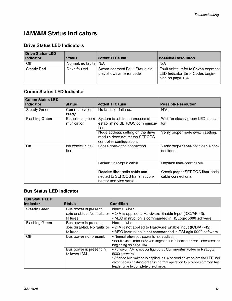
IAM/AM Status Indicators
Drive Status LED Indicators
Comm Status LED Indicator
Bus Status LED Indicator
Drive Status LED Indicator Status Potential Cause Possible Resolution Off Normal, no faults N/A N/A Steady Red Drive faulted Seven-segment Fault Status dis-
play shows an error code Fault exists, refer to Seven-segment LED Indicator Error Codes begin-ning on page 134.
Comm Status LED Indicator Status Potential Cause Possible Resolution Steady Green Communication
ready No faults or failures. N/A
Flashing Green Establishing com-munication
System is still in the process of establishing SERCOS communica-tion.
Wait for steady green LED indica-tor.
Node address setting on the drive module does not match SERCOS controller configuration.
Verify proper node switch setting.
Off No communica-tion
Loose fiber-optic connection. Verify proper fiber-optic cable con-nections.
Broken fiber-optic cable. Replace fiber-optic cable.
Receive fiber-optic cable con-nected to SERCOS transmit con-nector and vice versa.
Check proper SERCOS fiber-optic cable connections.
Bus Status LED Indicator Status Condition
Steady Green Bus power is present, axis enabled. No faults or failures.
Normal when:• 24V is applied to Hardware Enable Input (IOD/AF-43).• MSO instruction is commanded in RSLogix 5000 software.
Flashing Green Bus power is present, axis disabled. No faults or failures.
Normal when:• 24V is not applied to Hardware Enable Input (IOD/AF-43).• MSO instruction is not commanded in RSLogix 5000 software.
Off Bus power not present. • Normal when bus power is not applied.• Fault exists, refer to Seven-segment LED Indicator Error Codes section beginning on page 134.
Bus power is present in follower IAM.
• Follower IAM is not configured as CommonBus Follow in RSLogix 5000 software.• After dc bus voltage is applied, a 2.5 second delay before the LED indi-cator begins flashing green is normal operation to provide common bus leader time to complete pre-charge.

Repair
38 3A2152B
Repair
Base Pump Piston Replacement
1. Perform Shutdown, page 17.
2. Use a wrench to remove the outlet feed fittings at the bottom of the pump.
3. Remove the three nuts.
4. Remove the lower.
5. See the Dura-Flo Manual for rebuild information.
NOTE: Installation is the reverse of removal.
NOTE: When rebuilding base pump, verify piston pack-ings are assembled accordingly. Refer to FIG. 15 for visual clarity.
NOTE: Check balls are not installed.
FIG. 15: Base Pump
ti18108a
ti18109a
Note orientation of piston pack-ings when assembling.

Repair
3A2152B 39
Inhibitor/Catalyst/Color Pump Rebuild
FIG. 16: Inhibitor/Catalyst/Color Pump Rebuild
ti18110a
904
925
903
801 821814
906905
824802
806803
912 922 921 907
909 913924 915
920
932
9381003
902
Repair
40 3A2152B
Disassembly of 1093 valve sectionRefer to FIG. 16 for the following steps.
1. Remove motor (826) from Mounting Plate (818).
2. Remove valve from valve stack by removing the four screws (705) that are holding the valve to the plate (938).
3. On the right side of the valve, remove Valve End Cap (909). The Valve Piston (913) will be inside the end cap.
NOTE: If necessary, remove Valve Piston (913) from Valve End Cap (909) by applying low air pressure through valve air inlet to push out the Valve Piston (913).
4. Remove Seal Plate (924).
5. Repeat steps 3 and 4 with the left side of the valve.
6. Push the Spool/Sleeve (917) out with a finger. If the Spool/Sleeve does not slide out, tap gently using a wood or plastic dowel.
A worn spool and sleeve assembly must be replaced with a new (matched) assembly. If you are rebuilding multiple valves be sure to keep the spools and sleeves matched.
7. Remove Inlet/Outlet Block (932) from Valve Body (907).
8. Remove O-Rings (920) from Valve Body (907).
9. Remove Spool Wet Seal Retainers (915) on the left and right of the Valve Body (907).
10. Remove Valve Body (907) from Oil Cup Retainer (925) by removing Screws (927).
11. Remove Metering Sleeve (906) from Valve Body (7).
12. Remove Oil Cup Retainer (925) by removing screws (824) shoulder bolt.
13. Remove Seal Cup (903) from Oil Cup Retainer (925). Remove Posipak Rod Seal (904) from Seal Cup (903).
14. Slide Guide Rods out of Connection Block (806).
15. Remove Metering Rod (902) from Connection Block (806).
16. Remove Non Drip valve (1003) from Inlet/Outlet (932).
Assembly of 1093 valve sectionNOTE: Check the Metering Rod (902), Metering Sleeve (906), and Spool/Sleeve Assembly (917) and Valve Body (907) for wear. Replace as necessary.
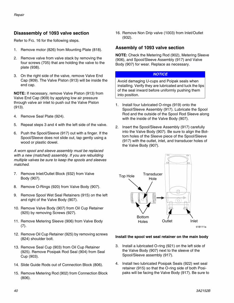
1. Install four lubricated O-rings (919) onto the Spool/Sleeve Assembly (917). Lubricate the Spool Rod and the outside of the Spool Rod Sleeve along with the inside of the Valve Body (907).
2. Insert the Spool/Sleeve Assembly (917) carefully into the Valve Body (907). Be sure to align the Bot-tom holes of the Sleeve piece of the Spool/Sleeve (917) with the outlet, inlet, and transducer holes of the Valve Body (907).
Install the spool wet seal retainer on the main body
3. Install a lubricated O-ring (921) on the left side of the Valve Body (907) next to the sleeve of the Spool/Sleeve assembly (917).
4. Install two lubricated Posipak Seals (922) wet seal retainer (915) so that the O-ring side of both Posi-paks will be facing the Valve Body (917). Be sure to
NOTICE
Avoid damaging U-cups and Poipak seals when installing. Verify they are lubricated and tuck the lips of the seal inward before uniformly pushing them into position.
ti18111a
Top Hole
Bottom Holes Outlet Inlet
Transducer Hole

Repair
3A2152B 41
tuck the lip of the Posipak into its cavity to avoid damage.
5. Position the wet seal retainer with the oil cup upwards and slide over the Spool part of the Spool/Sleeve Assembly (917) with the counterbore for the Seal Retainer (915) facing out. Slide the Seal Retainer (915) over the Spool and install two Screws (923). Install the Rod Sleeve and connect the motor and motor coupling assembly.
6. Repeat steps 3 through 5 for the right side Seal Plates.
Install the Metering Sleeve and Connect the Motor & Motor Coupling Assembly
7. Lubricate the dispense sleeve bore in the Valve Body (907). Insert the Metering Sleeve (906) into the Valve Body (907).
8. Place lubricated O-ring (905) over the Metering Sleeve (906) and against the Valve Body (907).
9. Insert the Seal Cup (903) into the Retainer Oil Cup (925).
10. Slide a lubricated Posipak Seal (904) into the Seal Cup (903) with the o-ring side facing down toward Valve Body (907).
11. Lubricate the Metering Rod (902) and slide carefully through the Posipak Seal (904), Seal Cup (903) and Oil Cup Retainer (925) so that the Metering Rod (902) projects about 1/2” through this assembly.
12. Using the projecting Metering Rod (902) to guide the assembly into the Metering Sleeve (906), slide the Oil Cup Retainer (925) down against the Valve Body (907) and secure with Screws (927).
13. Pull the Metering Rod (902) away from the Valve Body (907) so that the end is only slightly in the Metering Sleeve (906).
14. Slide the key slot in the Connection Block (804) over the end of the Metering Rod (902).
15. Insert the Guide Rods (803) through the Connection Block (806) and into the Oil Cup Retainer (925).
NOTE: If the Motor and Motor Coupling Assembly had been disassembled, then reassemble per the instruc-tions below before proceeding to step 19.
16. Position the Motor and Motor Coupling Assembly above the Main Body Assembly and bring them together so that the Guide Rods (803) enter their holes in the Drive Assembly (901) and the end of the Lead Screw (814) seats in the Connection Block (804).
17. Install the Screws (805/807) into the Connection Block (806).
18. Install the left Side Block 3-Slot (802) with Screws (824/808). Install the clear plastic Guards (822) so that the access hole in the guard toward the bottom. Secure with Screws (823).
Mount the Valve End Caps to the Seal Plate Cups
19. Install a lubricated U-cup Seal (912) into the groove of the left Spool Shift Piston (913). The piston is thicker on one side of the groove. The lip of the seal must be facing the thicker section.
20. Lubricate the bore in the End Cap (909). Slide the Spool Shift Piston (913) into the left End Cap (909) tucking the lip of the U-cup seal (912) into the End Cap (909) carefully.
21. Install shift spool position cycle detection sensors (926) with screws (928). Align Nubon sensor with hole in Seal Retainer (924).
22. Install the Piston/End Cap onto the left Spool Wet Retainer (915) using four Screws (908/931). Tighten the screws in a cross pattern gradually to prevent binding due to misalignment.
23. Push the Spool Rod (917) into the left side until the Spool Rod (917) contacts the piston. Repeat steps 19 through 22 for the right side.
24. Install lubricated O-rings (920) to the Valve Body (907) and attach the Inlet Block (932) with Screws.
25. Install the Inlet/Outlet Block (932) with Screws. Remount the valve. Install the home and spool sen-sors being careful not to overtighten the set screws. Install the air supply lines and connect the power.
Repair
42 3A2152B
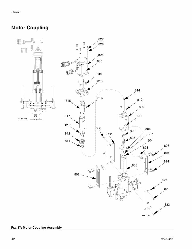
Motor Coupling
FIG. 17: Motor Coupling Assembly
ti18110a
ti18112a
827
828
826
830
819
818
816815
817
813
812
811
814
810
809
831
808
824
801
822
823
833
821
803
804
806
805
820823
822
802
807

Repair
3A2152B 43
Disassembly of motor coupling section1. Remove Screws (805) to disconnect Connection
Block (804) from Lead Screw Connector Block.
2. Remove Lead Screw Connecting Block from lead screw by removing the FHSC screw (807).
3. Remove Mounting Plate (818) from drive assembly by removing SHC Screws (819).
4. Remove bearing Retaining Sleeve (817) from drive assembly by removing screws (810).
5. Remove Lead Screw (814) and Lead Screw Nut (813) with the ball bearing assembly (812/811) attached.
Motor and motor coupling assembly1. Assemble Motor Coupler by inserting Roll Pins
(825) and Screws (816).
NOTE: This step is only required if the motor coupler has been disassembled for service or removed from the motor.
2. Assemble Lead Screw Nut (813) with Bearing (812) and E-ring (811).
3. Thread Lead Screw (814) into Lead Screw Nut assembly until lead screw is flush with top of nut.
4. Slide Lead Screw & Nut Assembly into Lead Screw Housing (809).
5. Slide Bearing Retaining Sleeve (817) on to the lead screw assembly, taking care to line up the slots in the two pieces (809) and (817). Secure in place with Screws (810).
6. Secure Motor Mounting Plate (818) to Lead Screw Housing (809) using Socket Head Cap Screws.
7. Place Motor Coupler (815) on motor shaft and lightly snug Screws (816) leaving about 3/8” of motor shaft visible between Motor Coupler and motor. Insert Motor Coupler (815) through Motor Mounting Plate (818), align 3 Roll Pins and insert into Lead Screw Nut (813) and gently seat the motor.
NOTE: This step is only required if the motor coupler has been disassembled for service or removed from the motor.
8. Remove motor and motor coupler, tighten Screws (816) and reassemble securing motor to Motor Mounting Plate using Socket Head Cap Screws (827).

Repair
44 3A2152B
Valve Stack Rebuild
FIG. 18: Valve Stack Assemblies
ti18113a
1217
1212
1201
1204
1202
1205
1213
1213
1204
1205
1204
1205
1204
1205
1208
1213
130513041305
1306
1307
13081309
1216
Mixer Step Face Up

Repair
3A2152B 45
The valve stack is a series of blocks put together with socket head cap screws. Each block contains a plastic mixer (1205). The only reason to service this would be if the material started to gel, if the color was being changed, or before a long shut down. If the material started to gel, the best place to start is the bottom block where the catalyst is injected. There should be no gell-ing above that point. To disassemble the valve stack:
1. Perform Shutdown, page 17.
2. Remove the base hose from the Swivel Fitting (1217) at the top of the stack.
3. Remove the inhibitor, catalyst and color valves from the valve stack. Remove the Bolts (705) from the Plate (938).
4. Turn off the flow of coolant to the Cooling Jacket (704) and Block (1309) and relieve any coolant pressure.
5. Remove the Cooling Jacket (704) from the Pipe Mixer (1308).
6. Remove the Pipe Mixer (1308) and valve stack from the screw on the press.
7. Remove the Cooling Block (1309) from the valve stack
8. Move the stack to a bench to disassemble.
9. Carefully use a pipe wrench to remove the Pipe Mixer (1308).
10. Remove the bottom four Socket Head Screws (1213) from the Bottom Outlet Block (1208).
11. Remove the Bottom Outlet Block (1208) from the Catalyst Pump Port (1203).
12. Remove the Plastic Mixer (1205) from the Block (1208).
NOTE: The old mixer should be replaced with a new one each time.
13. Remove the Top Inlet Block (1201) from the Inhibi-tor Pump Port (1203) by removing four Socket Head Cap Screws (1212).
14. Remove the Plastic Mixer (1205).
15. Remove the four Socket Head Cap Screws (1213) in the Inhibitor Pump Port Block (1203).
16. Remove the Inhibitor Pump Port Block (1203).
17. Remove the four Socket Head Cap Screws (1213) from either the Spacer Block (1206) or the Color Block (1206) if using kit 24M126.
18. Remove the Mixer (1205) from this Spacer Block (1206) or Color Block (1206).
Before reassembly, check all sealing surfaces for scratches. Make sure any traces of silicone are removed. Replace the Plastic Mixers (1205), the Top Inlet Block Oring (1202), and the other Block Orings (1204). Use an oring lubricant on the seals to reassem-ble.
Reassembly is the reverse of disassembly. Be sure the plastic mixers are positioned correctly with the small step facing up as shown. Refer to FIG. 18.

Repair
46 3A2152B
Position Sensor on Inlet/Outlet Valve Replacement
FIG. 19: Inlet/Outlet Valve
ti18117a
405
407
407
403
408
402404
409
406
401

Repair
3A2152B 47
See valve manual 310550 for more information.
1. Remove and bleed air pressure from valve.
2. Remove valve cap (402).
3. Disconnect coupling (404) from valve shaft (401).
4. Remove air cylinder (405) from valve cap (402).
5. Lubricate and replace o ring (403).
6. Perform any other valve maintenance as required. See Graco manual 310550.
7. Reattach air cylinder (405) to valve cap (402).
8. Pull air cylinder (405) shaft out and attach coupling (404).
9. Attach coupling (404) to valve shaft (401) and piston (401).

Parts
48 3A2152B
Parts
Control Frame Base Pump, 24M094
ti18114a
113
114
115
104,105,106
102,108,109
101,120
116
110,111
103
110,112
107
119117
118

Parts
3A2152B 49
Software already loaded when received.
Ref Part Description Qty101 16M370 FRAME,assembly,LSR,aluminum 1102 24L878 PUMP,base assembly,DURA-FLOW 750, 1103 24M007 VALVE,base assembly,DURA-FLOW 750,I 1104 24L933 ENCLOSURE,assembly,LSR select 1105 24L871 PANEL,back,assembly,LSR select,1 1106 24L890 CONTROL,wiring diagram,LSR select 1 1107 81/0136-G/25 GUARD,footswitch assembly,w/cord,15' 1108 16M397 CABLE,feedback,base pump,5 meter 1109 16M398 CABLE,power,base pump,5 meter 1110 24M118 VALVE,assembly,solenoid,base pump,A 2111 121022 ELBOW,swivel,1/4tube x 1/4NPT 1112 125733 FITTING,tee,1/4tube x 1/4 NPT 1113 24M050 HARNESS,assembly, LSR, stack 1114 24M049 HARNESS,assembly,LSR,stack,motor,11' 1115 24M051 HARNESS,assembly,LSR,stack,sensor,11' 1116 24M111 CLAMP,assembly,hose,(1)1-5/8ID 1117 24M112 CLAMP,assembly,hose,(3)1-5/8ID 1118 125968 COVER,cables,5-3/4”OD,16”LG 1119 114271 STRAP,retaining 6120 125920 COVER,T-slot,gray,78.74”,10mm 2
121 16K956 SOFTWARE,HMI,LSR 1122 16K957 SOFTWARE,PLC,LSR 1123 16K958 SOFTWARE,PLC,LSR,select 1

Parts
50 3A2152B
Base Pump Wet Section, 24L880
ti18115a
201
202

Parts
3A2152B 51
Ref Part Description Qty201 L180SS PUMP,recip, displacement 1202 16M221 HOUSING,valve,(7.5CM),base pump 1

Parts
52 3A2152B
Base Pump Lower, 24L878
ti18116a
318
319
310
313
312
314
315
316
317
301
302
303
308
304
305
309
305
306
307
311
305
306
307

Parts
3A2152B 53
Replacement Danger and Warning labels, tags, and cards are available at no cost.
Item not shown.
Ref Part Description Qty301 16K892 MOTOR,servo 1302 125874 ACTUATOR,linear,ET100,w/o motor 1303 121797 SCREW,cap,socket 4304 114766 BOLT,cap hex head 4305 101044 WASHER,plain 12306 100018 WASHER,lock,spring,1/2” 6307 555395 NUT,1/2-13 6308 16M223 PLATE,adapter,ET100,DF750,pump 1309 617374 PLATE,pump,mounting 1310 118435 GROMMET 1311 123999 SCREW,cap,hex head 4312 16M224 GUARD,tube,base pump 1
313 84/0130-27/11 LABEL,hand crush,1.3 X 1.1,triangle,ISO 1314 15F837 ROD,tie 3315 100128 WASHER,lock 3316 555396 NUT,5/8-11 hex 3317 24L880 pump,displacement,mod 1318 16M222 SHAFT,drive,holder,sensor,M27-2 1319 81/0440-1/11 SWITCH,proximity,24VDC,NO,PNP 1
320 81/0399/11 CONNECTOR,field,straight,female 1

Parts
54 3A2152B
Base Pump Inlet/Outlet Valves, 24L977
ti18117a
405
407
407
403
408
402404
409
406
401

Parts
3A2152B 55
Ref Part Description Qty401 918537 APPLICATOR,ball seat,1/2 port 1402 16M353 CAP,cylinder 1403 103338 PACKING,o-ring 1404 16M352 COUPLING,piston,air cylinder,cycle 1405 125917 CYLINDER,air, 1406 125918 SWITCH,proximity,4MM,PNP/NPN,24VDC,3W 2407 82/0217-A/11 MUFFLER,air,1/8NPT,mini 2408 121022 ELBOW,swivel,1/4TUBEX1/4NPT 2409 81/0398/11 CONNECTOR,field,straight 2

Parts
56 3A2152B
Base Pump Inlet/Outlet Valve Plumbing, 24M007
ti18118a
501
502504
505
506
507
510
508
509
501
502
503
505
504
506512513
514515
503
511

Parts
3A2152B 57
Ref Part Description Qty501 125925 FITTING,swivel,3/”4X1” 2502 15U426 BUSHING,reducing 2503 24L977 APPLICATOR,ball seat,1/2 port 2504 166242 FITTING,elbow,street,90 degree 2505 15M859 FITTING,adapter,male,swivel,1/2 SST 2506 114572 FITTING,nipple,hex 3507 V-565208080808SS CROSS,1/2NPT 1508 123980 FITTING,swivel,3/4X1/2 1509 122763 FITTING,elbow,straight,3/4NPT 1510 504174 BUSHING,pipe 1511 24L981 HOSE,coupled 1512 122656 BUSHING,1/2X1/4NPT 1513 124517 SENSOR,pressure,PGM,ambient 1514 81/0428/11 CONNECTOR,PT06F106S MIL 1515 81/0099-4/11 CORD,20/4,5A,PVC,300V,80degree C 10

Parts
58 3A2152B
Base Pump Inlet/Outlet Valve Plumbing, 24M118
ti18119a
604
608
605
602
603
606
607
604
608
605
602
603
606
607
601

Parts
3A2152B 59
Ref Part Description Qty per Valve601 123513 FERRULE,wire,18AWG 3602 81/0287-3/11 CORD,18/3,7A 8603 83/0028-C/11 CONNECTOR,cable,solenoid 1604 120900 VALVE,power,4W,SSSR,1/4NPT,24VDC 1605 121021 MUFFLER,air,1/4NPT 2606 121022 ELBOW,swivel,1/4TUBEX1/4NPT 2607 054130 TUBE,.250 OD 6608 15F979 SCREW,pan head 2

Parts
60 3A2152B
Valve Stack, 24L893
ti18160a
704 706
708
703
702
701
705,707
709
712
711
710

Parts
3A2152B 61
Ref Part Description 24L893 Qty
24M126 Qty
24M127 Qty
701 24L968 VALVE,1093,10A-4TS0-250-V-DISP 1702 24L969 VALVE,1093,10A-4TS0-625-V-DISP 1703 24M039 MIXER,stack assembly,(2)1093,w/cool 1704 24M040 JACKET,cooling assembly,3/4X12 pipe 1705 101682 SCREW,SHC,1/4-20X0.625 4706 24M048 VALVE,assembly 1707 110755 WASHER,plain 4708 24L969 VALVE,1093,10A-4TS0-625-V-DISP 1709 16M448 BLOCK,stack,module 1710 124517 SENSOR,pressure,PGM,ambient 1711 81/0428/11 CONNECTOR,PT06F1065 MIL 1712 81/0099-4/11 CORD,20/4,5A,PVC,300’,80 degree. 1

Parts
62 3A2152B
Inhibitor/Catalyst/Color Pump Drive (1093 Valve), 24L905
ti18112a
814
809
831
821
801
824
822
823
820
805806
807
803
804
823822
827
828
826
819
818
815
817
813
812
811
821808
802
824
816 810
825
808
916

Parts
3A2152B 63
Replacement Danger and Warning labels, tags, and cards are available at no cost.
Ref Part Description Qty801 01/2983/97 PLATE,tie,front,PD,1.5B 1802 01/2982/97 PLATE,tie,back,PD44 1803 01/2706-A/99 ROD,guide,1093,1.5BX2.0S 2804 A2010204 1093,connector,metering rod 1805 96/0260/98 SCREW,SHC,8-32X0.63,SS 2806 A2010205 1093,connector,lead screw 1807 96/0458/99 SCREW,FHSC,10-32X0.50 1808 96/0328-2/98 SCREW,SHC,shoulder 4809 01/2990/97 HOUSING,leadscrew 1810 96/0273/99 SCREW,BHSC,8-32X0.19 2811 V-98585A112 RING,retaining,external,0.625 1812 84/0129/11 BEARING,ball,.625IDX1.375OD 1813 16M285 NUT,leadscrew,drive 1814 01/2994-1/25 LEADSCREW,drive,1093 1815 16M284 COUPLER,leadscrew,12MM,motor,shaft 1816 96/0363/99 SCREW,SHC,6-32X0.38 2817 01/2992/97 RETAINER,bearing,leadscrew 1818 16M286 PLATE,moutning 1819 GC2192 SCREW,SHDC,SS,.164X.375 4820 01/2993-S/89 SPACER,drive nut 1821 A2010208 1093,spacer,drive 4822 01/2995-1/11 GUARD,side,1093 2823 297639 SCREW,cap,button head,8-32X.38 4824 96/0328-3/98 SCREW,SHC,shoulder 4825 96/0206/98 PIN,roll,1/8X.50,SS 3826 16K891 MOTOR,servo,enclosure 1827 113003 SCREW,SHC,10-32X0.63 4828 C19277 WASHER,lock,split,hi-collar 4
831 84/0130-27/11 LABEL,hand crush 1

Parts
64 3A2152B
Inhibitor/Catalyst/Color Pump Drive (1093 Valve), 24L969 and 24L968
927
925
903
904
905
902
906
907
909
934933
915
936
935
910
911
914
912913
924923 916
926
928
929
922
921
937
931910
909
908
911
914912
913924
929
915
923926,928
917921
922
917
919
939940938
ti18120a
930
920
932

Parts
3A2152B 65
Ref Item Description24L969
Qty24L969
Qty901 24L905 KIT,1093,driveE assembly,servo motor 1 1902 A2010207-10S 1093,rod,metering,5/8,SS 1
16M328 ROD,1093,metering,1/4,SS 1903 A2010203-10 1093,oil cup,large,5/8 1
16M329 CUP,1093,oil,large,1/4 1904 D2000064 POSIPAK,5/8IDX7/8OD 1
D2000042 POSIPAK,1/4IDX1/2OD 1905 103559 PACKING,o-ring 1 1906 A2010206-10D 1093,sleeve,metering,5/8 1
16M327 SLEEVE,1093,metering,1/4,PTFE 1907 16M324 VALVE,1093,main 1 1908 96/0509/98 SCREW,SHC,10-32X2.50 4 4909 16D002 CAP,END,air cylinder 2 2910 123453 FITTING,1/4tube x 1/8NPT 2 2911 111098 PACKING,o-ring,cylinder 2 2912 95/0601/01 U-CUP,1-3/16IDX1-1/2OD 2 2913 A2000009-1 1093,piston,spool 2 2914 01/2801-1/97 TUBE,AIR CYL,spool,1093 2 2915 A2000006-1 1093,retainer,seal,wet,spool valve 2 2916 110208 PLUG,pipe,headless,1/8NPT 4 4917 16M330 SPOOL,1092,assembly 1 1918 J1000002 PIN,ROLL,1/8X.38 2 2919 108195 PACKING,o-ring 4 4920 556553 O-RING,-008 FKM-A 2 2921 555684 O-RING,-018 FKM-A 2 2922 D2000040 POSIPAK,3/8IDX5/8OD 2 2923 95/0894/11 POSIPAK,1"IDX1-3/8"OD 2 2924 A2000007-1 1092,retainer,seal 2 2925 A2010202 1093,retainer,oil cup,large 1 1926 81/0440-1/11 SWITCH,proximity,24VDC,NO,PNP 2 2927 96/0307-1/99 SCREW,SHC,10-24X1.00 4 4928 96/0575/98 SCREW,FHSC,4-40X0.31 2 2929 B4000023 SCREW,SHC,10-32X1.25 4 4930 84/1050-400/11 DECAL,material 1 1931 617559 SCREW,cap,SCH 4 4932 24L906 NEEDLE,1092,adapter,single 1 1933 123538 BUTTON,snap-on,1/4tube 1 1934 61/2904-YL/11 TUBING,0.160IDX0.250OD 6 6935 123537 BUTTON,snap-on,1/4tube 1 1936 61/2904-GN/11 TUBING,0.160IDX0.250OD 6 6937 125916 SCREW,SHC,10-32X0.25 1 1

Parts
66 3A2152B
Needle Adapter Assembly, 24L906
938 16M326 BRACKET,mounting,module 1 1939 96/0125/99 SCREW,SHC,10-24X0.50 4 4940 100020 WASHER,lock,split,#10,MS 4 4941 81/0398/11 CONNECTOR,field,straight 1 1
Ref Item Description24L969
Qty24L969
Qty
ti18121a
1001
1002
1004
1003
1004
Ref Part Description Qty1001 124998 FITTING,adapter 11002 16M287 BLOCK,1092,inlet/outlet,9/16-18 11003 24L907 VALVE,assembly 11004 B4000016 SCREW,SHC,10-32X1.00 2

Parts
3A2152B 67
Non-Drip Valve, 24L907
Ref Part Description Qty1101 01/0013-S/98 STEM,NDV,5/8,11/16,special seat 11102 97/0208/98 SPRING,.250 ODX1.00LG,8.99LB 11103 16M288 HOUSING,5/8,SS,soft seat,SAE 11104 01/0014/98 PIN,NDV,5/8,11/16,SS 11105 103648 PACKING,o-ring 11106 16M289 VALVE,head,NDV,5/8,11/16,PTFE 11107 120336 O-RING,packing 1
ti18122a
1101
11061102
1103
1104
1107
1105

Parts
68 3A2152B
Valve Stack, 24M039
ti18123a
1217
1212
1201
1202
1213
1203
1213
1204
1205
1219
1204
1205
1203
1204
1205
1208
1213
1217
1202
1204
1201
12161216
1205
1204
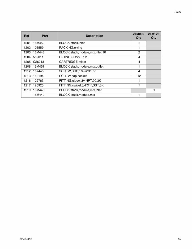
Parts
3A2152B 69
Ref Part Description 24M039 Qty
24M126 Qty
1201 16M450 BLOCK,stack,inlet 11202 103559 PACKING,o-ring 11203 16M448 BLOCK,stack,module,mix,inlet,10 21204 559011 O-RING,(-022) FKM 41205 C26213 CARTRIDGE,mixer 41208 16M451 BLOCK,stack,module,mix,outlet 11212 107445 SCREW,SHC,1/4-20X1.50 41213 113194 SCREW,cap,socket 121216 122763 FITTING,elbow,3/4NPT,90,3K 11217 125925 FITTING,swivel,3/4”X1”,SST,3K 11219 16M448 BLOCK,stack,module,mix,inlet 1
16M449 BLOCK,stack,module,mix 1
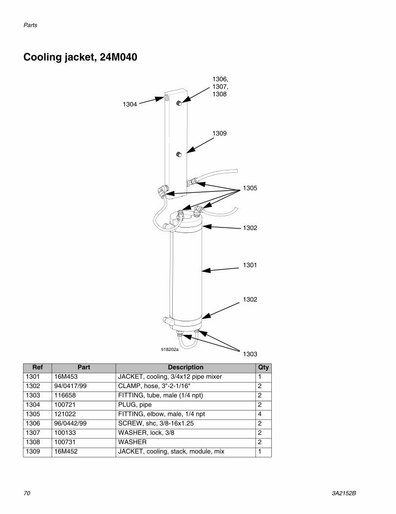
Parts
70 3A2152B
Cooling jacket, 24M040
Ref Part Description Qty1301 16M453 JACKET, cooling, 3/4x12 pipe mixer 11302 94/0417/99 CLAMP, hose, 3"-2-1/16" 21303 116658 FITTING, tube, male (1/4 npt) 21304 100721 PLUG, pipe 21305 121022 FITTING, elbow, male, 1/4 npt 41306 96/0442/99 SCREW, shc, 3/8-16x1.25 21307 100133 WASHER, lock, 3/8 21308 100731 WASHER 21309 16M452 JACKET, cooling, stack, module, mix 1
ti18202a
1304
1306,
1309
1305
1302
1301
1302
1303
1307,1308

Parts
3A2152B 71
Solenoid Valve, 24M048
Kit 24M126 adds an extra solenoid valve to the sys-tem.
Part not shown.
Ref Part Description 24M048 Qty
24M126 Qty
1401 83/0082/11 VALVE,power,4W,SSSR,24VDC 3 11402 83/0081/11 PLUG,1/4 11403 G0050125 VALVE,solenoid,manifold kit 1
1404 122522 CONNECTOR,5 pin 11405 551789 SCREW 21406 82/0337/11 PLUG,one-touch 1
1407 82/0414/11 MUFFLER 1
ti18105a
1403
1406
1402
1401

Parts
72 3A2152B
Control Cabinet Exterior, 24L993
ti181096a
1528
1527
1503,
1501
1514,
1512,
1520
1511
1524
1523
1519
1517
1525
1505,
1502
1526
1510
1521,
1504,1506,1508
1515
15131507,1508,1509
1522

Parts
3A2152B 73
Replacement Danger and Warning labels, tags, and cards are available at no cost.
Part not shown.
Ref Part Description Qty1501 24L932 ENCLOSURE,LSR select,painted 11502 16K902 CONTROL,panelview 700 PLUS 6 11503 81/2060-E/11 BUTTON,mush 11504 81/2060-EL/11 LEGEND,e-stop,60MM,plain 11505 81/2080-1/11 BLOCK,contact,NO 11506 81/2070/11 LATCH,operator 11507 81/2060-P/11 OPERATOR,PB,dual 11508 81/2081-1/11 BLOCK,contact,NC 21509 81/2072-2/11 LIGHT,LED,white,24VDC,latch 11510 16M354 FAN,ENC,22VAC,4” 11511 81/0369-EG/11 GRILL,exhaust,4”,w/filter 11512 81/0114-3/11 ALARM,audio 11513 81/0114-VC/11 COVER,volume control,audio alarm 11514 6690-34-299 ETHERNET bulkhead pass thru 11515 6690-34-300 ETHERNET cap & lanyward 11517 81/0372-2/86 CONNECTOR,PVC,1.25” 3
1518 5-742-B-TB8 T-BOLT KIT,10MM slot 81519 125795 GRIP,cord 61520 168491 EMBLEM,GRACO 1
1522 15M511 LABEL,warning,PR70 11523 81/1060-4/25 CONNECTOR,4P w/key 11524 84/0101-BI/11 LEGEND,start options 11525 84/0101-FC/11 LEGEND,control power 11526 84/0101-AT/11 LEGEND,audio power 11527 16K317 LABEL,legend,ethernet 1
1528 196548 LABEL,caution,shock 1

Parts
74 3A2152B
Control Cabinet Interior, 24L871
ti18125a
1623 1624 1625, 1627, 1622 1603, 1601 1629,1626 1628 1638
1630,
1610
1611
16121613
1606,
1631
1644
1613
1614
1615
16501618,
1641,
1621
1619
1643
1642
16181618,
1618,1632,1619
16191634,1638
1604
1634,
1609
1608
1602
1614
1617
1616
1615
1640

Parts
3A2152B 75
Part not shown.
Ref Part Description24L871
Qty24M126
Qty24M127
Qty24M128
Qty1601 16K903 PANEL,back,60X36 11602 6690-34-301 SWITCH,ethernet,5 port 11603 24X024 DISCONNECT assembly,fused,30AMP 11605 24L930 TERMINAL,strip assembly,LSR select 11606 16K875 CONTROL,programmable,L45 11607 16K878 MODULE,SERCOS,drive,L4X 1 11608 16K879 MODULE,power supply,24 11609 16K877 MODULE,ehternet bridge 11610 6690-34-243 ANALOG module 11611 6690-34-143 MODULE,input,16 11612 6690-34-248 16 point relay 11613 6690-34-224 CAP,end 11614 16K885 MODULE,power rail 1 11615 16K882 MODULE,integrated axis 1 11616 16K884 MODULE,axis 11617 16K883 MODULE,axis 11618 16K880 KIT,I/O,feedback,SERCOS 3 11619 16K881 BATTERY,servo 2 1
1620 16K876 CLAMP,cable,kinetix drive 11621 81/0495-6/11 CONTACTOR,4P,6A,24VDC 1 11622 123359 RELAY,contactor,30A 1 11623 123386 RELAY,24VDC coil,SPDT 1 11624 123296 CIRCUIT,breaker,2P,5A,UL489 21625 116500 HOLDER,fuse,safety 2 21626 116821 FUSE,Bussman 2 21627 81/0033-H3/11 BLOCK,fuse,TYPE-CC,3pole,30A,IP 1 11628 81/0033-20/11 FUSE,type-CC,20A,time delay 3 31629 117666 TERMINAL,ground 11630 6690-20-47 DISTRIBUTION block 11631 6690-20-59 DISTRIBUTION block cover 11632 121808 POWER SUPPLY,24VDC 11633 120997 CORDSET,EURO,male,5PIN 11634 16M305 AMPLIFIER,UV-10,18-24VDC 1 3 1
1635 6690-34-164 6FT ethernet cable 21636 6690-34-163 3 FT ethernet cable 11637 16K890 CABLE,fiberoptic 4 21638 116610 SCREW,mach 51
1639 295709 SCREW,SHC,8-32X0.75 21640 113003 SCREW,SHC,10-32X0.63 6 4 6 21641 81/0163-A/11 PANDUIT,2.0”X3.0”X6' 181642 514014 RAIL,mount 3.581643 81/0164-A/11 COVER,panduit,2”X6' 181644 125957 MODULE,memory 11650 16K886 MODULE,power rail,filler 3
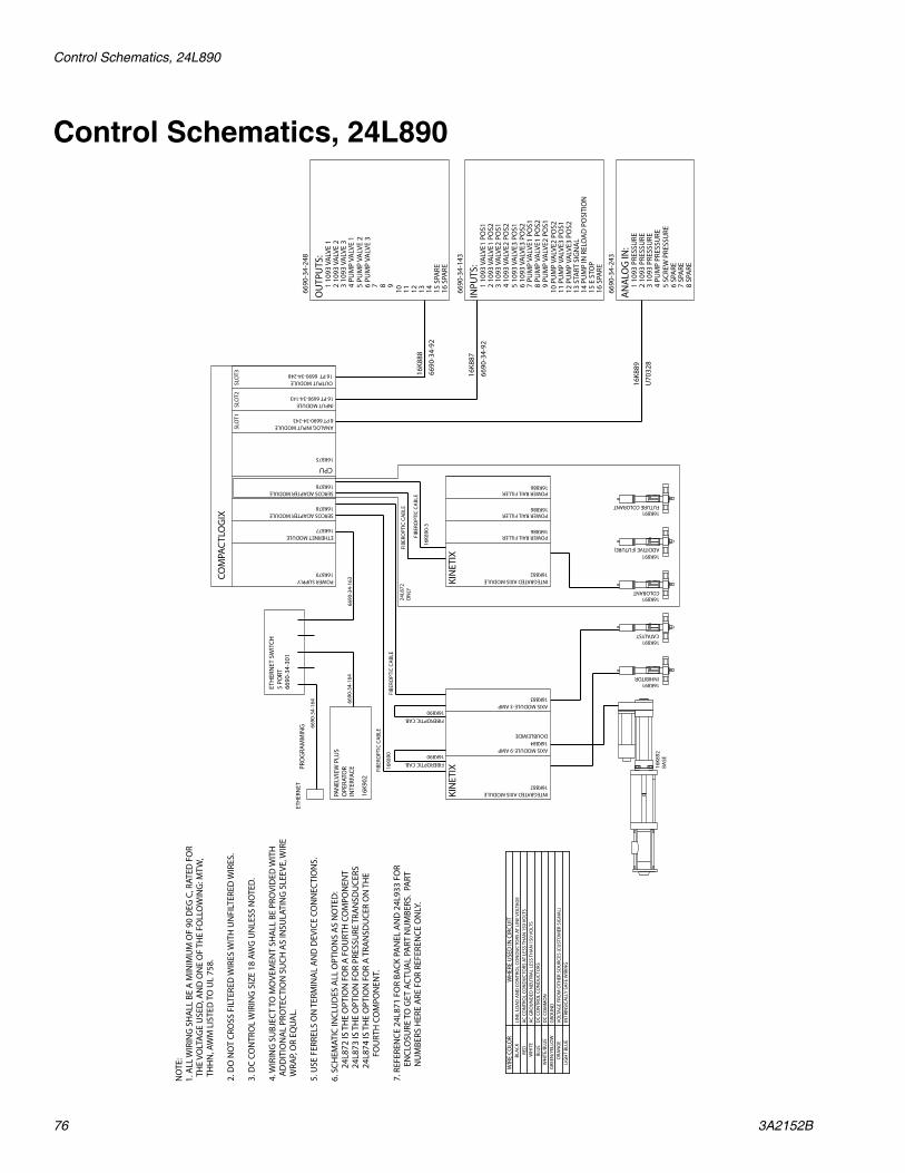
Control Schematics, 24L890
76 3A2152B
Control Schematics, 24L890N
OTE
:1.
ALL
WIR
ING
SH
ALL
BE
A M
INIM
UM
OF
90 D
EG C
, RAT
ED F
OR
TH
E VO
LTAG
E U
SED
, AN
D O
NE
OF
THE
FOLL
OW
ING
: MTW
, T
HH
N, A
WM
LIS
TED
TO
UL
758.
2. D
O N
OT
CRO
SS F
ILTE
RED
WIR
ES W
ITH
UN
FILT
ERED
WIR
ES.
3. D
C CO
NTR
OL
WIR
ING
SIZ
E 18
AW
G U
NLE
SS N
OTE
D.
4. W
IRIN
G S
UBJ
ECT
TO M
OVE
MEN
T SH
ALL
BE
PRO
VID
ED W
ITH
AD
DIT
ION
AL
PRO
TEC
TIO
N S
UCH
AS
INSU
LATI
NG
SLE
EVE,
WIR
E W
RAP,
OR
EQU
AL.
5. U
SE F
ERRE
LS O
N T
ERM
INA
L A
ND
DEV
ICE
CON
NEC
TIO
NS.
6. S
CHEM
ATIC
INCL
UD
ES A
LL O
PTIO
NS
AS
NO
TED
:
24
L872
IS T
HE
OPT
ION
FO
R A
FO
URT
H C
OM
PON
ENT
24L8
73 IS
TH
E O
PTIO
N F
OR
PRES
SURE
TRA
NSD
UCE
RS
24
L874
IS T
HE
OPT
ION
FO
R A
TRA
NSD
UCE
R O
N T
HE
FOU
RTH
CO
MPO
NEN
T.
7. R
EFER
ENCE
24L
871
FOR
BACK
PA
NEL
AN
D 2
4L93
3 FO
R
E
NCL
OSU
RE T
O G
ET A
CTU
AL
PART
NU
MBE
RS.
PART
NU
MBE
RS H
ERE
ARE
FO
R RE
FERE
NCE
ON
LY.
COM
PAC
TLO
GIX
8 PT 6690-34-243ANALOG INPUT MODULE
PAN
ELVI
EW P
LUS
OPE
RATO
R
16K878SERCOS ADAPTER MODULE
CPU
OUTPUT MODULE16 PT 6690-34-248
16K875
16K878SERCOS ADAPTER MODULE
16K877ETHERNET MODULE
16K879POWER SUPPLY
16 PT 6690-34-143INPUT MODULE
KIN
ETIX
16K884AXIS MODULE-9 AMP
16K882INTEGRATED AXIS MODULE
16K883AXIS MODULE-3 AMP
FIBE
ROPT
IC C
ABL
E
KIN
ETIX
16K882INTEGRATED AXIS MODULE
FIBE
ROPT
IC C
ABL
E
16K8
92BA
SE
16K891
CATALYST
INHIBITOR
ADDITIVE (FUTURE)
COLORANT
FUTURE COLORANT
DOUBLEWIDE
16K891
16K891
16K891
16K891
12 P
UM
P VA
LVE3
PO
S2
9 PU
MP
VALV
E2 P
OS1
11 P
UM
P VA
LVE3
PO
S1
10 P
UM
P VA
LVE2
PO
S2
5 10
93 V
ALV
E3 P
OS1
6
1093
VA
LVE3
PO
S2
7 PU
MP
VALV
E1 P
OS1
8
PUM
P VA
LVE1
PO
S2
2 10
93 V
ALV
E1 P
OS2
3
1093
VA
LVE2
PO
S1
4 10
93 V
ALV
E2 P
OS2
INPU
TS:
1 10
93 V
ALV
E1 P
OS1
15 E
STO
P
13 S
TART
SIG
NA
L
14 P
UM
P IN
REL
OA
D P
OSI
TIO
N
16 S
PARE
12 9
11
10 5 PU
MP
VALV
E 2
6 PU
MP
VALV
E 3
7
8
2 10
93 V
ALV
E 2
3
1093
VA
LVE
34
PUM
P VA
LVE
1
OU
TPU
TS:
1 10
93 V
ALV
E 1
15 S
PARE
13
14
16 S
PARE
INTE
RFAC
E
ETH
ERN
ET S
WIT
CH5
PORT
PRO
GRA
MM
ING
16K886POWER RAIL FILLER
SLO
T1SL
OT2
SLO
T3
5 SC
REW
PRE
SSU
RE
6 SP
ARE
7
SPA
RE
8 SP
ARE
2 10
93 P
RESS
URE
3
1093
PRE
SSU
RE
4 PU
MP
PRES
SURE
AN
ALO
G IN
:1
1093
PRE
SSU
RE
16K8
88
16K8
87
16K8
89
6690
-34-
248
6690
-34-
143
6690
-34-
243
6690
-34-
92
6690
-34-
92
U70
328
16K8
90FI
BERO
PTIC
CA
BLE
FIBEROPTIC CAB.16K890
FIBE
ROPT
IC C
ABL
E
16K8
90-3
FIBEROPTIC CAB.16K890
24L8
72O
NLY
6690
-34-
301
6690
-34-
163
6690
-34-
164
6690
-34-
164
16K9
02
16K886POWER RAIL FILLER
16K886POWER RAIL FILLER
ETH
ERN
ET
WH
ERE
USE
D IN
CIR
CUIT
LIN
E, L
OA
D A
ND
CO
NTR
OL
CON
DU
CTO
RS A
T LI
NE
VOLT
AGE
INTR
INSI
CALL
Y SA
FE W
IRIN
GVO
LTAG
E FR
OM
OTH
ER S
OU
RCES
(CU
STO
MER
SIG
NA
L)
AC G
ROU
ND
ED N
EUTR
AL
LESS
TH
AN
150
VO
LTS
AC C
ON
TRO
L CO
ND
UC
TORS
AT
LESS
TH
AN
150
VO
LTS
DC
CON
TRO
L CO
ND
UC
TORS
LIG
HT
BLU
E
WH
ITE/
BLU
E
WIR
E CO
LOR
GRE
EN/Y
ELLO
W
BLAC
K
GRO
UN
DD
C CO
MM
ON
ORA
NG
E
WH
ITE
BLU
E
RED

Control Schematics, 24L890
3A2152B 77
PG-1
1 2 3 4
BRN
BLK
BLU
BLK
1236
58
81/0
398/
11
PG-2
1 2 3 4
BRN
BLK
BLU
BLK
PG-3
1 2 3 4
BRN
BLK
BLU
BLK
PG-1
0
1 2 3 4
SHIE
LDRE
DBL
KG
RN
1225
22
5W
HT
1 2 3 4
BRN
WH
TBL
UBL
K
REF
1 2 3 4
BRN
WH
TBL
UBL
K
REF
1 2 3 4
BRN
WH
TBL
UBL
K
REF
1 2 3 4 5
SHIE
LD RED
BLK
WH
TBL
U
REF
PG-1
1
1 2 3 4
SHIE
LDRE
DBL
KG
RN
5W
HT
1 2 3 4 5
SHIE
LD RED
BLK
WH
TBL
U
REF
PG-1
2
1 2 3 4
SHIE
LDRE
DBL
KG
RN
5W
HT
1 2 3 4 5
SHIE
LD RED
BLK
WH
TBL
U
REF
1236
58
1236
58
GRE
Y CA
BLE
1212
01
PG-1
5
1 A C E F
SHIE
LD RED
WH
TG
RNW
HT
REF
81/0
428/
11
FDCBA E
INT
JMP
INT
JMP
CUT
ON
E EN
D O
FF
PG-1
7
1 2 3 4
BLK
7000
BLK
7060
BLK
7140
BLK
7420
1225
22
5RE
D 6
1 2 3 4 5
WH
TBL
UBL
KG
RY
REF
BRN
81/0
055-
MC4
/11
1236
58
1-1/
4" C
ON
DU
IT
HEA
T SH
RIN
K
81/0
398/
11
81/0
398/
11
1225
22
1225
22
24L8
72 O
NLY
24L8
73 O
NLY
24L8
74 O
NLY
24L8
73 O
NLY
I/O C
ABL
ES F
ROM
EN
CLO
SURE
TO
STA
CK
PX-V
110
93 IN
HIB
ITO
R SW
ITCH
ES
PX-V
210
93 C
OLO
R SW
ITCH
ES
PX-V
310
93 C
ATA
LYST
SW
ITCH
ES
PT-3
1093
CAT
ALY
ST T
RAN
SDU
CER
PT-2
1093
CO
LOR
TRA
NSD
UCE
R
PT-1
1093
INH
IBIT
OR
TRA
NSD
UCE
R
PT-5
SCRE
W T
RAN
SDU
CER
SOL-
OV
SOLE
NO
ID V
ALV
ES

Control Schematics, 24L890
78 3A2152B
L1
L1
L2
L220
3-24
0V/3
PH/5
0-60
HZ
60 AMP
DISC-1
30 A
MP
L1L2
240
249
247
245
242
210
238
236
234
232
230
228
226
224
222
220
218
214
216
212
208
206
204
202
200
241
248
244
246
243
211
239
237
235
233
231
229
227
225
223
221
219
215
217
213
209
207
205
203
201
290
299
297
295
292
260
288
286
284
282
280
278
276
274
272
270
268
264
266
262
258
25625
4
252
250
291
298
294
296
293
261
289
287
285
283
281
279
277
275
273
271
269
265
267
263
259
25725
5
253
251
L3 L3
L3
L2
CB1
L3
5A
2060
2080
PS-1 N
24V
DC
LFGV-V+
68
10 A
WG
DC
COM
HA
RNES
S 12
0997
BRN
WH
T
BLU
1
PG-P
S1
2
PG-P
S1
3
PG-P
S1
16 A
WG
8BL
U
824
VDC
6D
C CO
M
BLU
6W
HT
/BL
U0X
PB-1
BI
CRM
-1
34
2560
CRM
-1
A1
A2
PL-1W
0
PB-1
A
XO
REM
OTE
STO
P
2561
2562
2563
2563
PB-2
XO
E-ST
OP
CON
TRO
L PO
WER
6W
HT
/BL
U
86 6
6W
HT
/BL
U
CRM
-2
A1
A2
625
63
2060
2080
L2L2
CB2
5A
2160
2180
PS-2 L2L1 PE
10 A
WG
14 A
WG
2160
2180
8BL
U6
WH
T/B
LU
86
HM
I-1
PE+
_
ETH
ERN
ETPO
RT
86
CAB-
1
FU-L1
FU-L2
FU-L3
MCR
1
A1
A2
6W
HT
/BL
U6
8
CRM
-1
1314
2680
826
81
MCR
2
A1
A2
6W
HT
/BL
U6
TO K
2000
RAC
K1
TO K
2000
RAC
K226
82
POW
ER S
UPP
LYO
N P
LC
CR-2
1114
CR-3
1114
1218
08
16K8
79
81/0
194-
30/2
5
(3) 8
1/01
96-3
0/11
1232
96
1232
9681
/049
5-6/
11
81/0
495-
6/11
1233
59
1233
59
1233
86
1233
86
6690
-34-
301
8BL
U6
WH
T/B
LU
86
ETH
ERN
ET P
ORT
+
_
86
CAB-
2
HM
I
PLC
5 4 3 2 1
CAB-
3BU
LKH
EAD
6690
-34-
299
L1
L2FA
N
14A
16M
354
24L8
72 O
NLY
24L8
72 O
NLY
310,
312,
314
360,
362,
364
6690
-34-
164
6690
-34-
164
6690
-34-
163
16K9
02
698
WHT/BLU6W
HT
/BL
U6
WH
T/B
LU
8BL
U
BLU
CON
TRO
L PO
WER
BLK
BLK
L1
L2
ETH
ERN
ET
ET-1

Control Schematics, 24L890
3A2152B 79
340
349
347
345
342
310
338
336
334
332
330
328
326
324
322
320
318
314
316
312
308
306
304
302
300
341
348
344
346
343
311
339
337
335
333
331
329
327
325
323
321
319
315
317
313
309
307
305
303
301
390
399
397
395
392
360
388
386
384
382
380
378
376
374
372
370
368
364
366
362
358
356
354
352
350
391
398
394
396
393
361
389
387
385
383
381
379
377
375
373
371
369
365
367
363
359
357
355
353
351
L3L1
L2
L1L2
L3
IAM
-1
FU-3
20 A
MP
L1
L2
L3FU
-4
FU-5
12
34
MCR
1
56
L331
4031
41
L231
2031
21
L131
0031
01
FU-1
10 A
MP
L1
L2
FU-2
L230
60
L130
40
CRM
-2
34
3001
6816
K882
1 CO
NT
EN+
2 CO
NT
EN-
L1L2
L3
AM
-1
16K8
84
AM
-2
16K8
83
1 L1
2 L2
3 L3
4 G
ND
5 D
C+
6 D
C-
1 C
TRL
1
2 C
TRL
2
1
2
3 4
U V
W
GN
D
1
2
43
BRAKE
CR-2
A1
A2
1
2
3 4
U V
W
GN
D
IAM
-2
FU-8
20 A
MP
L1
L2
L3FU
-9
FU-1
0
12
34
MCR
2
56
L336
4036
41
L236
2036
21
L136
0036
01
FU-6
10 A
MP
L1
L2
FU-7
L235
60
L135
40
CRM
-1
12
3501
6816
K882
1 CO
NT
EN+
2 CO
NT
EN-
1 L1
2 L2
3 L3
4 G
ND
5 D
C+
6 D
C-
1 C
TRL
1
2 C
TRL
2
CR-3
A1
A2
81/0
033-
20/1
181
/003
3-H
3/11
1165
0011
6821
1233
59
1233
8612
3386
81/0
495-
6/11
3000
81/0
495-
6/11
3500
5 14
6 -10 +
GRN
WH
T/G
RNG
RYW
HT/
GRY
ORG
WH
T/O
RG
2 5 614
BLK
WH
T/BL
KRE
DW
HT/
RED
ORG
WH
T/O
RG
1
10 11
4
3
GRN
WH
T/G
RNG
RY
24L8
72 O
NLY
BRN
BLK
BLU
GRN
/YEL
SHIE
LD/B
RAID
BRN
BLK
BLU
GRN
/YEL
BATMOTOR
FEEDBACK
DAT
A+/
IM+
EPRW
_5VM
(2)
ECO
MM
(2)
DAT
A-/
IM-
MO
TOR
CABL
E (B
LK)
16M
396
INCO
MIN
G C
ABL
EG
ROU
ND
ED P
AD
SHIE
LD/B
RAID
MO
TOR
CABL
E (O
RG)
16M
398IN
HIB
ITO
RA
BSO
LUTE
EN
COD
ER16
K891
M2
BASE
ABS
OLU
TE E
NCO
DER
16K8
92M
1
1
2
3 4
U V
W
GN
D
1
2
43
BRAKE
5 14
6 -10 +
GRN
WH
T/G
RNG
RYW
HT/
GRY
ORG
WH
T/O
RG
BRN
BLK
BLU
GRN
/YEL
SHIE
LD/B
RAID
BAT
SHIE
LD/B
RAID
MOTORFEEDBACK
DAT
A+/
IM+
EPRW
_5VM
(2)
ECO
MM
(2)
DAT
A-/
IM-
MO
TOR
CABL
E (B
LK)
16M
396
ENCO
DER
CA
BLE
(BLK
)16
M39
5
INCO
MIN
G C
ABL
EG
ROU
ND
ED P
AD
COLO
RA
BSO
LUTE
EN
COD
ER16
K891
M4
1
2
3 4
U V
W
GN
D
5 14
6 -10 +
GRN
WH
T/G
RNG
RYW
HT/
GRY
ORG
WH
T/O
RG
BRN
BLK
BLU
GRN
/YEL
SHIE
LD/B
RAID
BATMOTOR
FEEDBACK
DAT
A+/
IM+
EPRW
_5VM
(2)
ECO
MM
(2)
DAT
A-/
IM-
MO
TOR
CABL
E (B
LK)
16M
396
INCO
MIN
G C
ABL
EG
ROU
ND
ED P
AD
CATA
LYST
ABS
OLU
TE E
NCO
DER
16K8
91M
3
CUT
PRO
TEC
TIVE
CO
VER
BACK
EXP
OSI
NG
BRA
IDSH
IELD
/BRA
ID
ENCO
DER
CA
BLE
(BLK
)16
M39
5
CUT
PRO
TEC
TIVE
CO
VER
BACK
EXP
OSI
NG
BRA
ID
SHIE
LD/B
RAID
ENCO
DER
CA
BLE
(BLK
)16
M39
5
CUT
PRO
TEC
TIVE
CO
VER
BACK
EXP
OSI
NG
BRA
ID
MOTORFEEDBACK
DAT
A+/
IM+
EPRW
_5VM
(2)
ECO
MM
(2)
DAT
A-/
IM-
INCO
MIN
G C
ABL
EG
ROU
ND
ED P
AD
SHIE
LD/B
RAID
ENCO
DER
CA
BLE
(GRN
)16
M39
7
CUT
PRO
TEC
TIVE
CO
VER
BACK
EXP
OSI
NG
BRA
IDTS
BM+
BM-
AM
+A
M-
X100
X11
H L
H L
H L
X100
X15
H L
81/0
033-
20/1
181
/003
3-H
3/11
1165
0011
6821
1233
59
66
3060
3040
3560
3540
WH
T/B
LU
WH
T/B
LU

Control Schematics, 24L890
80 3A2152B
540
549
547
545
542
510
538
536
534
532
530
528
526
524
522
520
518
514
516
512
508
506
504
502
500
541
548
544
546
543
511
539
537
535
533
531
529
527
525
523
521
519
515
517
513
509
507
505
503
501
590
599
597
595
592
560
588
586
584
582
580
578
576
574
572
570
568
564
566
562
558
556
554
552
550
591
598
594
596
593
561
589
587
585
583
581
579
577
575
573
571
569
565
567
563
559
557
555
553
551
88
24VD
C
24VD
C
BLU
6D
C CO
M6D
C CO
M
V IN
O+
V/I IN
O-
I IN O
+
ANLG
COM
NC NC
INH
IBIT
OR
VALV
E 1
PRES
SURE
COLO
RAN
TVA
LVE
2PR
ESSU
RE
CATA
LYST
VALV
E 3
PRES
SURE
BASE
D
URA
-FLO
WPR
ESSU
RE
21
35
46
OFFO
N
1 2 3 4 5 6
A B C D E F
+PO
WER
-OU
TPU
T/R
ETU
RN+O
UTP
UT
SHU
NTC
AL
ENA
BLE
+EXC
ITAT
ION
-EXC
ITAT
ION
+SIG
NA
L-S
IGN
AL
SHU
NT
CAL
RESI
STO
R
78
RED
BLK
GRN
WH
T50
31
5011
5011
PG-1
0
5432
5020
5010
5000
5030
5011
5031
SLO
T 1
88
24VD
C
24VD
C
BLU
688
6
COURSEZERO
FINEZERO
FINEGAIN
10V
5V 3V
WHT/BLU
V IN
1+
V/I IN
1-
I IN 1+
ANLG
COM
OFFO
N
1 2 3 4 5 6
A B C D E F
+PO
WER
-OU
TPU
T/R
ETU
RN+O
UTP
UT
SHU
NTC
AL
ENA
BLE
+EXC
ITAT
ION
-EXC
ITAT
ION
+SIG
NA
L-S
IGN
AL
SHU
NT
CAL
RESI
STO
R
AM
P-2
RED
BLK
GRN
WH
T51
61
5041
5041
PG-1
1
PT-2
5432
5150
5140
5130
5160
5041
5161
688
6
COURSEZERO
FINEZERO
FINEGAIN
10V
5V 3V
V IN
2+
V/I IN
2-
I IN 2+
ANLG
COM
OFFO
N
1 2 3 4 5 6
A B C D E F
+PO
WER
-OU
TPU
T/R
ETU
RN+O
UTP
UT
SHU
NTC
AL
ENA
BLE
+EXC
ITAT
ION
-EXC
ITAT
ION
+SIG
NA
L-S
IGN
AL
SHU
NT
CAL
RESI
STO
R
RED
BLK
GRN
WH
T52
91
5271
5271
PG-1
2
5432
5280
5270
5260
5290
5271
5291
688
6
COURSEZERO
FINEZERO
FINEGAIN
10V
5V 3VPOW
ERTR
AN
SDU
CER
AM
P-1
PT-1
AM
P-3
PT-3
V IN
3+
V/I IN
3-
I IN 3+
ANLG
COM
21
35
46
OFFO
N
1 2 3 4 5 6
A B C D E F
+PO
WER
-OU
TPU
T/R
ETU
RN+O
UTP
UT
SHU
NTC
AL
ENA
BLE
+EXC
ITAT
ION
-EXC
ITAT
ION
+SIG
NA
L-S
IGN
AL
SHU
NT
CAL
RESI
STO
R
78
RED
BLK
5421
5401
5401
F PG-1
4
DCBA
5410
5400
5390
5420
5401
5421
688
6
COURSEZERO
FINEZERO
FINEGAIN
10V
5V 3VAM
P-4
PT-4
E
+EXC
IT
-EXC
IT
-OU
TPU
T+O
UTP
UT
GRN
WH
T
6D
C CO
M6D
C CO
M
V IN
4+
V/I IN
4-
I IN 4+
ANLG
COM
NC NC
WHT/BLU
V IN
5+
V/I IN
5-
I IN 5+
ANLG
COM
V IN
6+
V/I IN
6-
I IN 6+
ANLG
COM
V IN
7+
V/I IN
7-
I IN 7+
ANLG
COM
21
35
46
OFFO
N
1 2 3 4 5 6
A B C D E F
+PO
WER
-OU
TPU
T/R
ETU
RN+O
UTP
UT
SHU
NTC
AL
ENA
BLE
+EXC
ITAT
ION
-EXC
ITAT
ION
+SIG
NA
L-S
IGN
AL
SHU
NT
CAL
RESI
STO
R
78
RED
5531
5511
5511
F PG-1
5
DCBA
5520
5510
5500
5530
5511
5531
688
6
COURSEZERO
FINEZERO
FINEGAIN
10V
5V 3VAM
P-5
PT-5
E
21
35
46
OFFO
N
78
21
35
46
78
NO
TE: S
MA
LL T
RAN
SDU
CERS
HAV
E JU
MPE
R SE
T TO
10V
,
LA
RGE
TRA
NSD
UCE
RS H
AVE
JUM
PER
SET
TO 5
V.
RED
BLK
GRN
WH
T
RED
BLK
GRN
WH
T
RED
BLK
GRN
WH
T
RED
BLK
GRN
WH
T
RED
BLK
GRN
WH
T
#10-
32
#10-
32
#10-
32
1/4N
PT
1/4N
PT
SCRE
WPR
ESSU
RE
+EXC
IT
-EXC
IT
-OU
TPU
T+O
UTP
UT
RED
BLK
WH
TBL
U
1SH
IELD
SHIEL
D
1SH
IELD
SHIEL
DRE
DBL
KW
HT
BLU
1SH
IELD
SHIEL
DRE
DBL
KW
HT
BLU
POW
ERTR
AN
SDU
CER
POW
ERTR
AN
SDU
CER
POW
ERTR
AN
SDU
CER
POW
ERTR
AN
SDU
CER
BLK
GRN
WH
T
24L8
73 O
NLY
24L8
74 O
NLY
24L8
73 O
NLY
24L8
73 O
NLY
SHIEL
D
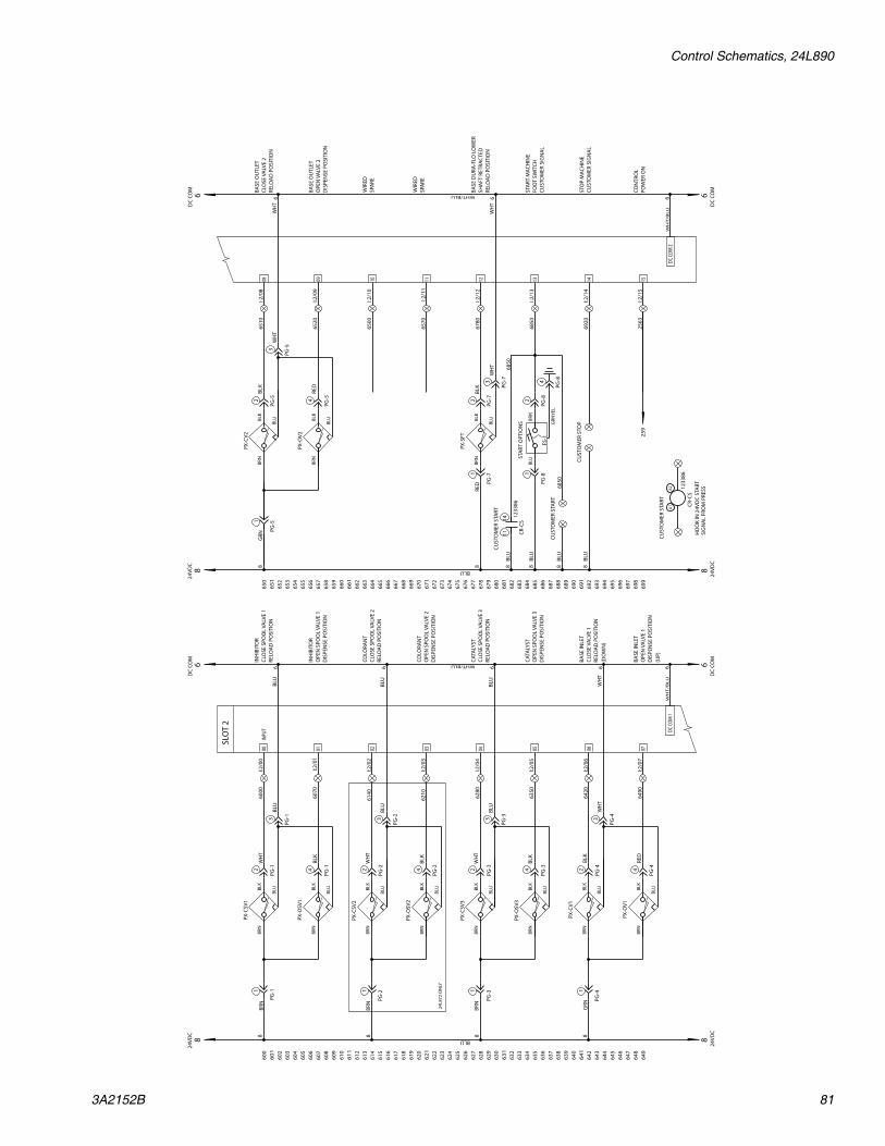
Control Schematics, 24L890
3A2152B 81
640
649
647
645
642
610
638
636
634
632
630
628
626
624
622
620
618
614
616
612
608
606
604
602
600
641
648
644
646
643
611
639
637
635
633
631
629
627
625
623
621
619
615
617
613
609
607
605
603
601
690
699
697
695
692
660
688
686
684
682
680
678
676
674
672
670
668
664
666
662
658
656
654
652
650
691
698
694
696
693
661
689
687
685
683
681
679
677
675
673
671
669
665
667
663
659
657
655
653
651
SLO
T 2
DC C
OM 2
0706050403
15141312
020100
11100908
DC C
OM 1
6W
HT
/BL
U
I:2/0
0IN
PUT
6000
I:2/0
1
I:2/0
2
I:2/0
3
I:2/0
4
I:2/0
5
I:2/0
6
I:2/0
7
I:2/0
8
I:2/0
9
I:2/1
0
I:2/1
1
I:2/1
2
I:2/1
3
I:2/1
4
I:2/1
5
6W
HT
/BL
U
88
24VD
C6
DC
COM
24VD
C6
DC
COM
BLU
WHT/BLU
88
24VD
C6
DC
COM
24VD
C6
DC
COM
BLU
WHT/BLU
INH
IBIT
OR
CLO
SE S
POO
L VA
LVE
1RE
LOA
D P
OSI
TIO
N
STA
RT M
ACH
INE
FOO
T SW
ITCH
CUST
OM
ER S
IGN
AL
STO
P M
ACH
INE
CUST
OM
ER S
IGN
AL
8BR
N1
PG-1
2
PG-1
BLK
63
PG-1
BLU
PX-C
SV1
6070
INH
IBIT
OR
OPE
N S
POO
L VA
LVE
1D
ISPE
NSE
PO
SITI
ON
BRN
4
PG-1
BLK
BLU
PX-O
SV1
6140
COLO
RAN
TCL
OSE
SPO
OL
VALV
E 2
RELO
AD
PO
SITI
ON
8BR
N1
PG-2
2
PG-2
BLK
6BL
U
PX-C
SV2
6210
COLO
RAN
TO
PEN
SPO
OL
VALV
E 2
DIS
PEN
SE P
OSI
TIO
N
BRN
4
PG-2
BLK
BLU
PX-O
SV2
6280
CATA
LYST
CLO
SE S
POO
L VA
LVE
3RE
LOA
D P
OSI
TIO
N
8BR
N1
PG-3
2
PG-3
BLK
6BL
U
PX-C
SV3
6350
CATA
LYST
OPE
N S
POO
L VA
LVE
3D
ISPE
NSE
PO
SITI
ON
BRN
4
PG-3
BLK
BLU
PX-O
SV3
6420
BASE
INLE
TCL
OSE
VA
LVE
1RE
LOA
D P
OSI
TIO
N(D
OW
N)
81
PG-4
2
PG-4
6
PX-C
V1
6490
BASE
INLE
TO
PEN
VA
LVE
1D
ISPE
NSE
PO
SITI
ON
(UP)
4
PG-4
PX-O
V1
6510
BASE
OU
TLET
CLO
SE V
ALV
E 2
RELO
AD
PO
SITI
ON
82
PG-5
6
PX-C
V2
6520
BASE
OU
TLET
OPE
N V
ALV
E 2
DIS
PEN
SE P
OSI
TIO
N
4
PG-5
PX-O
V2
6500
6570
6780
BASE
DU
RA-F
LO L
OW
ERSH
AFT
RET
RAC
TED
RELO
AD
PO
SITI
ON
8RE
DBR
N1
PG-7
2
PG-7
BLK
63
PG-7
BLU
PX-S
FT
FS-1
6850
8BL
U1
PG-8
2
PG-8
BRN
4
PG-8
GRN
YEL
8BL
U68
50
CUST
OM
ER S
TART
6920
8BL
UCU
STO
MER
STO
P
1
PG-5
GRN
GRN
3
PG-2 3
PG-3 3
PG-4
WH
T
3
PG-5
WH
T
BRN
BLK
BLU
BRN
BLK
BLU
RED
RED
BRN
BLK
BLU
BRN
BLK
BLU
BLK
WH
T
BRN
WH
T
BLU
BLK
BRN
WH
T
BLU
BLK
BRN
WH
T
BLU
BLK
24L8
72 O
NLY
CR-C
S
A1
A2
CR-C
S
1114
1233
86
1233
86
CUST
OM
ER S
TART
HO
OK
IN 2
4VD
C ST
ART
SIG
NA
L FR
OM
PRE
SS
CON
TRO
LPO
WER
ON
2563
259
BLU
CUST
OM
ER S
TART
8BL
U68
50
WIR
EDSP
ARE
WIR
EDSP
ARE
WH
T
BLU
BLU
BLU
WH
T
WH
T
STA
RT O
PTIO
NS
BLK
BLK
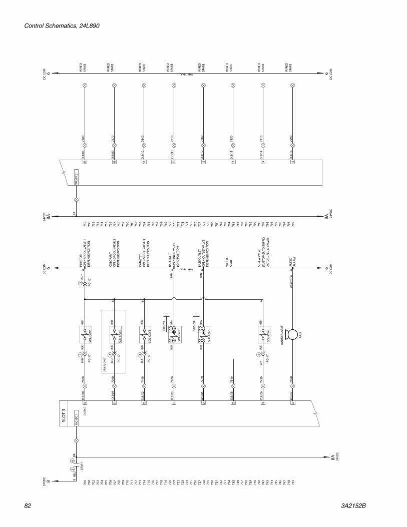
Control Schematics, 24L890
82 3A2152B
740
749
747
745
742
710
738
736
734
732
730
728
726
724
722
720
718
714
716
712
708
706
704
702
700
741
748
744
746
743
711
739
737
735
733
731
729
727
725
723
721
719
715
717
713
709
707
705
703
701
790
799
797
795
792
760
788
786
784
782
780
778
776
774
772
770
768
764
766
762
758
756
754
752
750
791
798
794
796
793
761
789
787
785
783
781
779
777
775
773
771
769
765
767
763
759
757
755
753
751
SLO
T 3
0706050403
15141312
01 02
OUTP
UT00
11100908
VAC
VDC
1VA
C VD
C 2
8A8A 24VD
C6
DC
COM
24VD
C6
DC
COM
WHT/BLU
8A
8
6D
C CO
M
24VD
C6
DC
COM
WHT/BLU
8A
O:3
/00
7000
O:3
/01
O:3
/02
O:3
/03
O:3
/04
O:3
/05
O:3
/06
7420
O:3
/07
O:3
/08
O:3
/09
O:3
/10
O:3
/11
O:3
/12
O:3
/13
O:3
/14
O:3
/15
INH
IBTO
RO
PEN
SPO
OL
VALV
E 1
DIS
PEN
SE P
OSI
TIO
N
SCRE
W V
ALV
E
SOL-
OSV
1
BLK
1
PG-1
7
2
PG-1
7
RED
6
7060
COLO
RAN
TO
PEN
SPO
OL
VALV
E 2
DIS
PEN
SE P
OSI
TIO
NSO
L-O
SV2
BLK
3
PG-1
7
RED
6
7140
CATA
LYST
OPE
N S
POO
L VA
LVE
3D
ISPE
NSE
PO
SITI
ON
SOL-
OSV
3
BLK
4
PG-1
7
RED
6
7200
BASE
INLE
TO
PEN
INLE
T VA
LVE
LOA
D P
OSI
TIO
N
BLU
BRN
6
7270
BASE
OU
TLET
OPE
N O
UTL
ET V
ALV
E D
ISPE
NSE
PO
SITI
ON
BLU
BRN
6
7340
7490
AUD
IOA
LARM
7500
WIR
EDSP
ARE
7570
WIR
EDSP
ARE
7640
WIR
EDSP
ARE
7710
WIR
EDSP
ARE
7780
WIR
EDSP
ARE
7850
WIR
EDSP
ARE
7910
WIR
EDSP
ARE
7990
WIR
EDSP
ARE
CRM
-1
56 8A 24
VDC
8BL
U
WH
TBR
N
BLU
BLK
SOL-
OV4
BLK
5
PG-1
7
RED
6W
HT
/BL
U
AA
-1
6
24L8
72 O
NLY
(CU
STO
MER
TO
SU
PPLY
ACTU
AL
FLU
ID V
ALV
E)
GRY
+ 1- 2
SOL-
OV1
BRN
BRN
GRN
/YEL
+ 1- 2
SOL-
OV2
GRN
/YEL
WIR
EDSP
ARE
AUD
IO A
LARM

Control Schematics, 24L890
3A2152B 83

HMI Operation Overview
84 3A2152B
HMI Operation Overview
To navigate between screens press the button at the bottom of the screen for the desired screen.
STARTUP/ MAIN MENU SCREEN
ALARM STATUS SCREEN
ALARM HISTORY SCREEN
PRESSURE LOGS SCREEN
COLOR PRESSURE / TORQUE / SPEED
LOG SCREEN
CAT. PRESSURE / TORQUE / SPEED
LOG SCREEN
INHIBITOR PRESS. / TORQUE / SPEED
LOG SCREEN
BASE PRESSURE / TORQUE / SPEED
LOG SCREEN
STATUS SCREEN
DRIVE / VALVE CON-TROL SCREEN
PRESSURE SETUP SCREEN
RATIO CHECK SETUP SCREEN
HOME SETUP SCREEN
AUTO MODE SCREEN
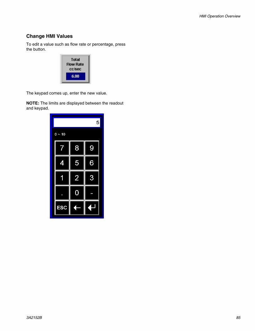
HMI Operation Overview
3A2152B 85
Change HMI ValuesTo edit a value such as flow rate or percentage, press the button.
The keypad comes up, enter the new value.
NOTE: The limits are displayed between the readout and keypad.
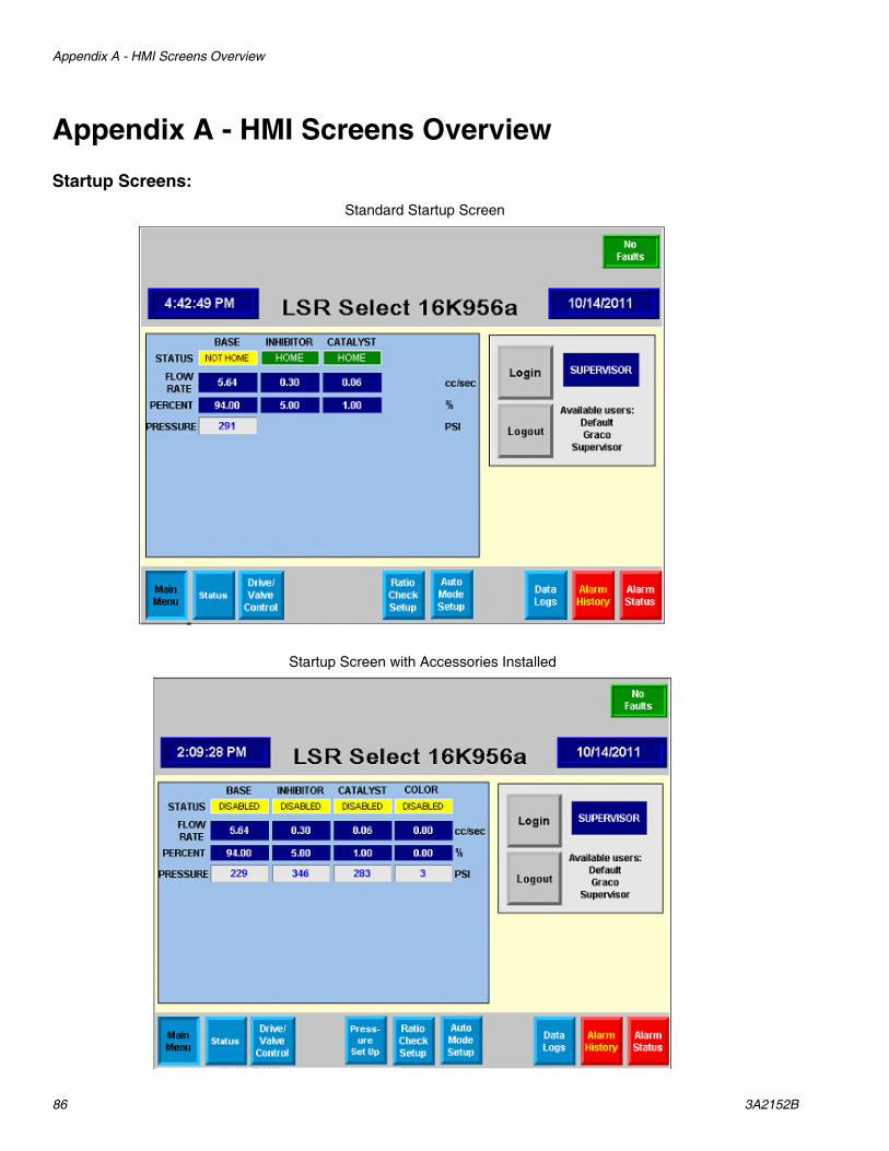
Appendix A - HMI Screens Overview
86 3A2152B
Appendix A - HMI Screens OverviewStartup Screens:
Standard Startup Screen
Startup Screen with Accessories Installed

Appendix A - HMI Screens Overview
3A2152B 87
NOTE: Various parts of the display are hidden based on what system is ordered or who is logged on.
1. In the upper right corner of this screen (and every screen) there is an indicator that says if there is a fault or not. The fault can be determined by looking at the Alarm Status screen by hitting the button in the lower right hand corner. Refer to Machine Alarms, page 28 for fault descriptions.
2. The gray box contains the number and revision of the program along with the time and date.
3. The first line in the blue box shows the status of each drive motor. The status may read:
• Fault: There is a drive fault.• Disabled: The drive needs enabled.• Home: The motor is in the home position and
ready to dispense.• Dispensing: The motor is moving and the pump
the motor is attached to should be dispensing.• Loading: The motor is moving and the pump the
motor is attached to should be moving towards the home position.
4. The second line in the blue box shows the settings for the current flow rate of each pump.
5. The third line shows the settings for current percent of each component to be dispensed.
6. The forth line show the pressure at the base pump and for part number 24M127 will show the pressure for the other pumps.

Appendix A - HMI Screens Overview
88 3A2152B
Status Screens:
Standard Status Screen
Status Screen with Accessories Installed

Appendix A - HMI Screens Overview
3A2152B 89
The Status screen pictorially represents the system and status of each item.
1. Base pump on left of screen:
a. Far left valve indicator shows if the base inlet valve is in the opened or closed position.
b. Right valve indicator shows if the base outlet valve is in the opened or closed position.
c. A pressure indicator shows the pressure of the base pump when loading or dispensing.
d. The box under the pressure indicator shows the drive status. This is the same status box that shows on startup screen.
2. The valve stack on the right of the screen.
This shows various assemblies depending on what has been installed on the system.
a. If the pressure is displayed, the screen shows the material feed pressure on the valve when the valve is in the load position and the pressure of the material when being injected into the stack when the valve is dispensing.
b. The box above the pressure reading indicated the drive status. This is the same status box that shows up on the startup screen.
Assembly Inhi
bito
r
Cat
alys
t
Col
or
Pre
ssur
e
24M093
24M126
24M127
24M128

Appendix A - HMI Screens Overview
90 3A2152B
Drive/Valve Control Screen:
Standard Drive/Valve Control Screen

Appendix A - HMI Screens Overview
3A2152B 91
Each gray box shows indicators and controls for the noted pump. The controls in the lower right box will operate all valves.
1. BASE/INHIBITOR/CATALYST valves windows, also COLOR if 24M126 is used. These windows control the pump indicated in the upper left corner of the window.
a. STATUS INDICATOR: The upper right corner has the drive status indicator. This is identical to the drive indicator on the startup and status screens.
b. ENABLE/DISABLE PUSHBUTTONS AND INDICATOR: On power up the drives are dis-abled. The indicator below the enable and dis-able push button will read “Disabled”. The drive must be enabled in order to run. In auto mode all drives must be enabled, even if they are not part of the recipe. For example, if base purging with base and inhibitor only, the catalyst drive would still need to be enabled. To enable the drive, press the enable push button. The indicator below will read “Enabled”. To disable the drive, for example to reset a fault, press the disable push button
c. HOME PUMP/CYCLE PUMP/EXTEND PUMP: If after enabling the drive, the indicator shows “Not Home”, The drive needs to be homed. Press the HOME PUMP push button to home the drive. All drives must be in the home posi-tion to start a shot in the auto mode. A drive does not have to be in the home position to be powered up. The CYCLE PUMP push button is used to make an individual pump take a single shot. The pump mode must be set in ratio check
and the drive must be enabled and in the home position. The pump will dispense a fixed shot and the flow rate defined on the RATIO CHECK SETUP screen. This is used for troubleshooting an individual pump. The EXTEND PUMP push button (base only) is used to cycle the pump to its fully extended position for priming. After the base pump is fully extended, pressing the HOME PUMP push button will return the pump to the home position.
d. OPEN/CLOSE INLET/OUTLET VALVE (base pump only): These push buttons manually open and close the inlet and outlet valves to the base pump in the MANUAL MODE. To open the inlet valve, push the OPEN INLET VALVE button. The indicator below will read “OPEN”. To close the inlet valve, push the CLOSE INLET VALVE push button. The indicator will read “CLOSED”. The same works for the outlet valve.

Appendix A - HMI Screens Overview
92 3A2152B
2. ALL VALVES:
a. ENABLE/DISABLE DRIVES: These push but-tons work the same as the ENABLE/DISABLE DRIVE push buttons for each individual compo-nent, they just enable all the pumps or disable all the pumps at the same time. The enabled/disabled status is indicated in each individual component.
b. DRIVE FAULT RESET push button: If there is a drive fault (indicated in the status of each com-ponent or in the upper right corner of any screen), pushing the drive fault reset button will reset the fault.
c. DRIVE SHUTDN RESET push button: Neces-sary to reset the drive for certain faults if shut down. Use this push button to reset the drive if a fault shuts down the machine.
d. SET AUTO/RATIO/MAN'L mode push buttons: These are used to set the machine mode. When connected to the press the mode should be set to auto mode. Push the SET AUTO MODE push button. In auto mode, the button color will change from gray to green and will read “IN AUTO MODE”. The ratio check and manual modes are set the same way. The ratio check mode is used to run a pump individually and the manual mode is used for manually toggling valves when priming.
e. OPEN/CLOSE/AUTO SCREW VALVE push buttons and indicator. These buttons are used to setup the customer supplied valve between the outlet of the mixer and entrance of the screw. During normal running in auto mode the valve should be set to AUTO by pushing the AUTO SCREW VALVE push button. The indi-cator beneath the push buttons will read “AUTO”. The valve is set to be held open or closed by pushing the OPEN or CLOSE SCREW VALVE button. The valve should be held open or closed for priming and clean out.
f. RESET OVERTRAVEL FAULT push button (only visible when supervisor is logged in). This is one method used to reset an over travel fault which occurs when a pump axis goes beyond the defined range.
g. Status box in lower right corner (only visible when supervisor is logged in): This is used for additional troubleshooting. The status box dis-plays the actual motor position, actual motor speed, pressure and motor torque while running for each component.
NOTE: Negative speed or torque value indicates the motor is moving in thee negative direction. The position for home is 0.0, +/-.02 for the base, +/-.002 for the inhib-itor and catalyst.

Appendix A - HMI Screens Overview
3A2152B 93

Appendix A - HMI Screens Overview
94 3A2152B
Pressure Setpoint Screens:
Pressure Setpoint screen for basic system (24M093).NOTE: This screen is only accessible when the supervisor is logged in:
Pressure Setpoint screen for all (24M093, 24M126, 24M127, 24M128):

Appendix A - HMI Screens Overview
3A2152B 95
1. BASE/INHIBITOR/CATALYST/COLOR/MIXED Cur-rent Pressure (PSI) readout: This is the actual pressure in the pumps. If the pump is in the reload position, the readout shows the pressure of the material being pumped into the pump. If the pump is dispensing, the readout shows the pressure of the material being pumped to the stack. The MIXED pressure reading is the value between the mixer outlet and the inlet to the screw.
2. BASE/INHIBITOR/CATALYST/COLOR/MIXED high limit: This is the pressure that will shut the machine down if reached.
3. BASE/INHIBITOR/CATALYST/COLOR/MIXED low limit: This is the pressure that will shut the machine down if the pressure dips below. This is useful to shut down the system is a pump runs out of material and the component isn't being added to the mix. To ignore the low level, enter zero.
4. ENABLE/DISABLE PRESSURE SHUTDOWN push buttons and indicator. Push the Enable Pressure Shutdown button to enable the shutdown on a pres-sure fault.
NOTE: This is the default value. The indicator below the push buttons will read “ENABLED”. To disable the shut-down, push the Disable Pressure Shutdown button. It is recommended to leave this feature enabled. Check to see if it only looks at the low when dispensing.
5. ENABLE/DISABLE PRESSURE ALARM push but-tons and indicator. Push the Enable Pressure Alarm button to enable the alarm on a pressure fault.
NOTE: This is the default value. The indicator below the push buttons will read “ENABLED”. To disable the alarm, push the Disable Pressure Alarm button. It is rec-ommended to leave this feature enabled. This is used to keep running on a pressure fault, however the user will get an alarm signal that the pressure went over or under the specified values. When the pressure shut down is enabled, the alarm is also enabled.
6. CLEAR PRESSURE FAULT push button. In the event of a pressure shutdown fault, the system will not run again until the pressure is brought into the limits and the Clear Pressure Fault push button is pressed.
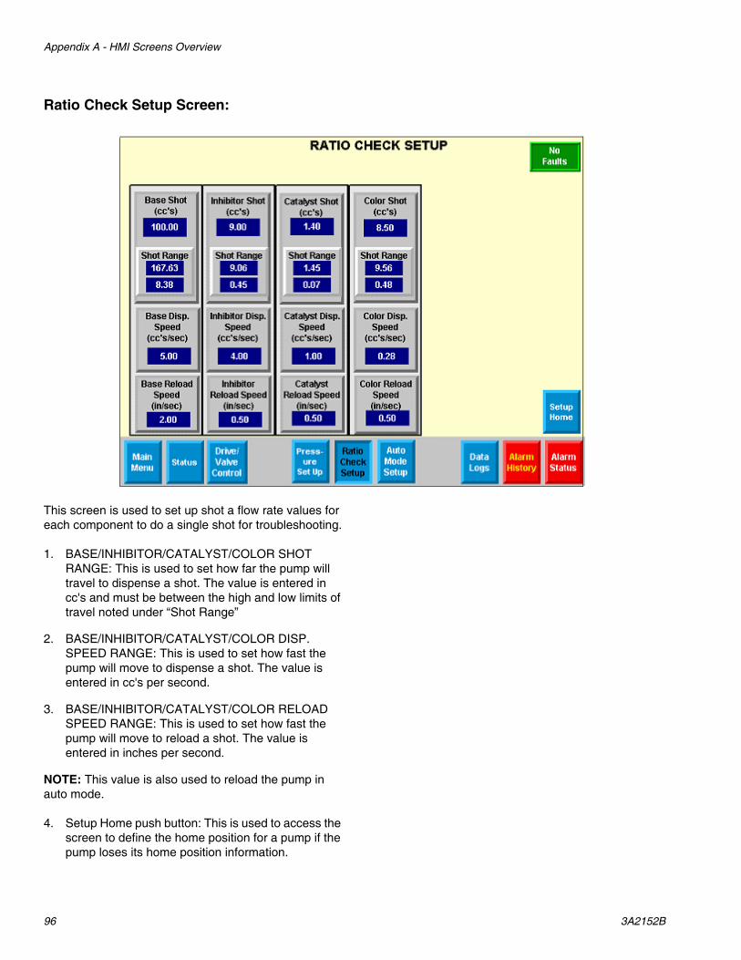
Appendix A - HMI Screens Overview
96 3A2152B
Ratio Check Setup Screen:
This screen is used to set up shot a flow rate values for each component to do a single shot for troubleshooting.
1. BASE/INHIBITOR/CATALYST/COLOR SHOT RANGE: This is used to set how far the pump will travel to dispense a shot. The value is entered in cc's and must be between the high and low limits of travel noted under “Shot Range”
2. BASE/INHIBITOR/CATALYST/COLOR DISP. SPEED RANGE: This is used to set how fast the pump will move to dispense a shot. The value is entered in cc's per second.
3. BASE/INHIBITOR/CATALYST/COLOR RELOAD SPEED RANGE: This is used to set how fast the pump will move to reload a shot. The value is entered in inches per second.
NOTE: This value is also used to reload the pump in auto mode.
4. Setup Home push button: This is used to access the screen to define the home position for a pump if the pump loses its home position information.

Appendix A - HMI Screens Overview
3A2152B 97
Setup Home (accessible by supervisor only):
This screen is used to define the home position for a pump if the pump loses its home position information. This only needs to be redone if the connection between the pump motor encoder and drive are disconnected.
1. ENABLE/DISABLE DRIVE push button and indica-tor: Identical function to buttons on DRIVE/VALVE CONTROL screen.
2. SET HOME push button: Used to set motor position to zero when pump is in the home position.
3. Position box: Show the current position of the pump motor. When the SET HOME push button is pushed, this should read close to zero.
See Appendix C - Setting Home Position on Pumps starting on page 105.

Appendix A - HMI Screens Overview
98 3A2152B
Auto Mode Setup Screen:
This screen is used to set up the recipe for the base, inhibitor, and catalyst (color also if 24M126 is used) in AUTO MODE.
1. TOTAL FLOW RATE (cc/sec) data entry in the TOTAL MIX box: This lets the user change the flow rate of mixed material that will load the screw on the press.
2. MAX SHOT POSSIBLE (cc) readout in the TOTAL MIX box: This shows how much material can be expected out of the pumps before they will reload.
NOTE: The shot in AUTO MODE is based on the time the signal from the press is held on. If the mold size pump sizes don't match, the screw may not be able to refill in a single pump shot. The value shown in this box is calculated from the percentages entered in each com-ponent below.
3. BASE/INHIBITOR/CATALYST/COLOR FLOW RATE (cc/sec) readout: This shows the calculated flow rate each pump will run at to achieve the flow rate entered in the total mix box and the percentage of each component needed in the recipe.
4. BASE PERCENT OF MIX: This is a readout only. The readout changes based on raising and lowering
the percentages of the other components. In order to dispense 100% base, adjust the inhibitor, catalyst and color percentages to zero.
5. INHIBITOR PERCENT OF MIX: This can be adjusted up or down by either pushing the square which will bring up the keypad to let an operator enter a numeric percentage or the up down arrow keys can be pushed to change the percentage in 0.05% increments/decrements.
6. CATALYST PERCENT OF MIX: This may be setup to be fixed at one percent. If this option is set to allow any user to change the value, the value can be adjustable the same way as the INHIBITOR PERCENT OF MIX. This value is not recommended to deviate from one percent.
7. COLOR PERCENT OF MIX: This only shows up with kit 24M126. The value adjusts the same way the INHIBITOR PERCENT OF MIX does.
8. CYCLE PUMPS push button. This will dispense the recipe at the flow rate as long as the button is held down. The button works the same way as the footswitch or customer signal. When the signal is dropped the pumps will reload.
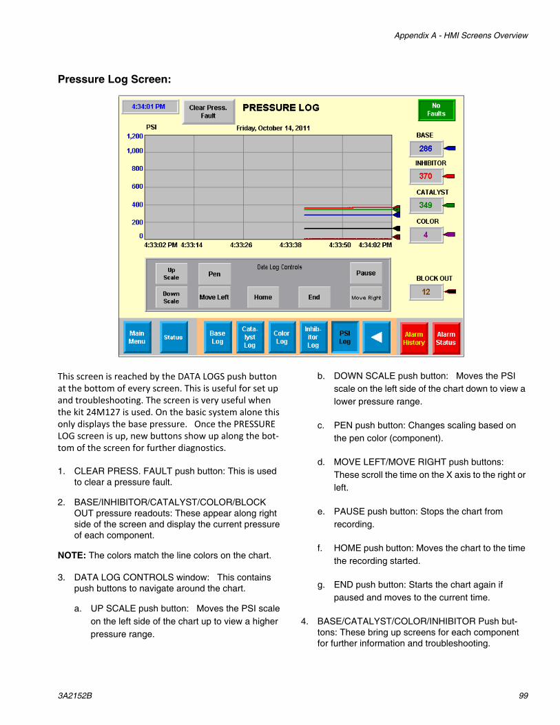
Appendix A - HMI Screens Overview
3A2152B 99
Pressure Log Screen:
This screen is reached by the DATA LOGS push button at the bottom of every screen. This is useful for set up and troubleshooting. The screen is very useful when the kit 24M127 is used. On the basic system alone this only displays the base pressure. Once the PRESSURE LOG screen is up, new buttons show up along the bot‐tom of the screen for further diagnostics.
1. CLEAR PRESS. FAULT push button: This is used to clear a pressure fault.
2. BASE/INHIBITOR/CATALYST/COLOR/BLOCK OUT pressure readouts: These appear along right side of the screen and display the current pressure of each component.
NOTE: The colors match the line colors on the chart.
3. DATA LOG CONTROLS window: This contains push buttons to navigate around the chart.
a. UP SCALE push button: Moves the PSI scale on the left side of the chart up to view a higher pressure range.
b. DOWN SCALE push button: Moves the PSI scale on the left side of the chart down to view a lower pressure range.
c. PEN push button: Changes scaling based on the pen color (component).
d. MOVE LEFT/MOVE RIGHT push buttons: These scroll the time on the X axis to the right or left.
e. PAUSE push button: Stops the chart from recording.
f. HOME push button: Moves the chart to the time the recording started.
g. END push button: Starts the chart again if paused and moves to the current time.
4. BASE/CATALYST/COLOR/INHIBITOR Push but-tons: These bring up screens for each component for further information and troubleshooting.

Appendix A - HMI Screens Overview
100 3A2152B
BASE/CATALYST/INHIBITOR/COLOR LOG screens:
These are accessible from the PRESSURE LOG SCREEN. These screens are identical for each component; the base component is shown below as an example.
1. CLEAR DRIVE FAULT Push button: Clears faults on all drives. The button has the identical function to the CLEAR DRIVE FAULT push button on DRIVE/VALVE control screen.
2. ENABLE/DISABLE DRIVE Push buttons and Indi-cator: These enable or disable the drive. They have the identical function as the ENABLE/DIS-ABLE DRIVE push buttons on the DRIVE/VALVE SCREEN.
3. HOME PUMP/CYCLE PUMP Push buttons and indicator: These buttons home or cycle the pump. The function is identical to the HOME PUMP/CYCLE PUMP push buttons on the DRIVE/VALVE screen.
4. DATA LOG CONTROLS Window: The push buttons in this window work the same as they do in the PRESSURE LOG screen.
5. PRESSURE (psi) Readout: This shows the actual pressure valve of the component.
NOTE: This may not show if the option (24M127, 24M128) is not being used.
6. TORQUE (%) Readout: This displays the percent-age of full torque the motor is using.
NOTE: The torque value may read a negative value. The negative sign indicates the direction the motor is turning.
7. SPEED (RPS) Readout: This displays the actual speed of the motor in revolutions per second.
NOTE: The speed value may read a negative value. The negative sign indicates the direction the motor is turning.

Appendix A - HMI Screens Overview
3A2152B 101
ALARM HISTORY Screen:
This displays ALL alarms that have occurred.
1. The blue window contains the date and time the alarm and a description of the alarm. A list of alarm descriptions are in Machine Alarms on page 28.
2. SORT Push button: switches the order from newest to oldest or oldest to newest.
3. The assorted arrow keys page/scroll up or down the lists.

Appendix A - HMI Screens Overview
102 3A2152B
ALARM STATUS Screen:
This screen displays all active alarms. Once an alarm is corrected, the alarm is removed from this screen.
1. ALARM SILENCE Push button: If an alarm triggers the audio alarm, this button will silence the alarm.
2. ALARM RESET Push button: Some alarms require an operator to acknowledge the alarm by manually pushing this button.
3. The assorted arrow keys page/scroll up or down the list.
4. RESET ALARM DATA Push button: NEED TO SEE WHAT THIS DOES
5. SORT Push button: switches the order from newest to oldest or oldest to newest.
6. CLEAR PRESSURE FAULT Push button: This needs to be pushed to clear a pressure fault. The function of this is identical to the CLEAR PRES-SURE FAULT button on the PRESSURE SETUP SCREEN.

Appendix A - HMI Screens Overview
3A2152B 103
ALARM POP UP Screen:
Whenever an alarm occurs, this pops up to inform the operator there is a problem. This information also goes to the ALARM STATUS SCREEN.
1. CLEAR Push button: This clears the alarm.
2. ALARM SILENCE Push button: If an alarm triggers the audio alarm, this button will silence the alarm.
3. CLOSE Push button: This closes the pop up screen.
NOTE: The alarms are still captured on the ALARM HISTORY or ALARM STATUS screens.

Appendix B - Logging In and Out
104 3A2152B
Appendix B - Logging In and OutOn power up, the user is the default with limited access to screens. To log in to the supervisor level:
1. Press the login button on the Startup screen.
2. The login entry screen appears.
3. Press User (F2) button to enter supervisor. The Keyboard screen appears.
4. Type in supervisor and enter (the lower right key).
5. The Login entry screen pops up again.
6. Press Password (F3) button to enter the password. The Keyboard screen pops up again.
7. Type in the password “5810” and hit enter.
8. If the password is correctly entered, the Startup screen will show the user as supervisor.
9. To logout, press the logout button on the startup screen. The screen will show Default as the user if the Supervisor is logged out.
10. Items the supervisor only has access to:
a. The PRESSURE SETPOINTS screen.
b. The RATIO CHECK SETUP screen.
c. The SETUP HOME screen.

Appendix C - Setting Home Position on Pumps
3A2152B 105
Appendix C - Setting Home Position on PumpsThe motors driving the pumps have absolute encoders on them and do not lose their position on loss of power. However, if the encoder cables are disconnected, the home positions need to be reset.
NOTE: If the electrical connections between the encoder and drive need to be disconnected, make sure the actuator is in the home position before disconnect-ing the connector. This ensures everything is in position when the connector is reattached and the below steps will not be necessary to perform.
1. Login as supervisor and go to the SETUP HOME screen.
2. Disable the drives. The motors will be able to be turned manually.
3. Locate home position for the base pump.
a. Locate the base pump so the actuator is extended about 4-1/2”.
b. Remove the motor from the actuator.
c. Using a wood dowel rod, turn the coupling in the actuator to move to the home position. CW retracts, CCW extends.
d. Reattach the motor to the actuator.
4.50"
ti18127a
ti18128a

Appendix C - Setting Home Position on Pumps
106 3A2152B
4. Locate home position for the inhibitor, catalyst, and color pumps (1093 valves).
NOTE: There is no reason to disconnect the motors to move the couplings for these pumps.
a. Locate the inhibitor, catalyst and color pumps so there is about 5/16” between the block and connection bar.
b. Insert a screwdriver in the lower slot and turn the coupling.
c. Turning the coupling clockwise retracts the shaft, turning counter-clockwise extends the shaft.
5. When the pump home positions are set, push the SET HOME button.
6. Press the ENABLE DRIVE button.
7. The motor positions will now read zero
5/16"
ti18129a
ti18130a

Appendix D - Selecting the Outlet Valve, Mounting the Stack to the Press
3A2152B 107
Appendix D - Selecting the Outlet Valve, Mounting the Stack to the PressRecommended for the customer to connect an auto-matic shutoff valve between the screw on the press and the LSR Select mixer. The LSR select has a solenoid valve and controls to connect a double acting valve.
The mixer outlet is 3/4”NPT male. When the valve stack is attached to the screw, care should be taken to ensure the valve stack is mounted rigidly. External brackets may be required.
Outlet valve controls on HMI
ti18105a1/4” Air Supply for Outlet Valve

Technical Data
108 3A2152B
Technical Data
* Catalyst and inhibitor can be incremented individu-ally in 0.1% increments.
Flow Rate . . . . . . . . . . . . . . . . . . . . . . . . . . . . . . . . . . . 2.5 to 10 cc's per second.
Ratio Range:
* Catalyst . . . . . . . . . . . . . . . . . . . . . . . . . . . . . . . . . 0% - 1%
* Inhibitor . . . . . . . . . . . . . . . . . . . . . . . . . . . . . . . . . 0% - 6%
Base . . . . . . . . . . . . . . . . . . . . . . . . . . . . . . . . . . . . . 92% - 100%
Pigment (Optional) . . . . . . . . . . . . . . . . . . . . . . . . . . 0% - 6%
Shot Size Range . . . . . . . . . . . . . . . . . . . . . . . . . . . . . . 50 to 180 cc's, depending on ratio
Cycle Rate. . . . . . . . . . . . . . . . . . . . . . . . . . . . . . . . . . . Dispense into screw varies depending on shot size and flow rate. Pump reload time is 5 seconds
Maximum Fluid Pressre. . . . . . . . . . . . . . . . . . . . . . . . . 1000 psi (7 MPa, 69 bar)
Wetted Parts . . . . . . . . . . . . . . . . . . . . . . . . . . . . . . . . . 303 stainless steel, 304 stainless steel, polytetrafluoro-ethylene (PTFE), ultra high molecular weight polyeth-ylene (UHMW-PE) and fluoropolymer elastomer
Feed System Requirements (Not Included) . . . . . . . . . Pressure feed systems that can feed the pumps at a minimum of 400 psi (2.8 MPa, 28 bar).Base inlet: 1 inch female NPT.Catalyst/Inhibitor/Pigment inlet: ¼ inch JIC-4 male, 37° flare.
Press Interface . . . . . . . . . . . . . . . . . . . . . . . . . . . . . . . 3/4 inch NPT male thread to screw, inlet valve on screw required. Maintained 24 vdc signal from press to activate shot.
Sound Pressure. . . . . . . . . . . . . . . . . . . . . . . . . . . . . . . 74.5 dB(A)
Weight, Valve Stack . . . . . . . . . . . . . . . . . . . . . . . . . . . 35 pounds (15.8 Kg)
Weight, Base Pump and Electrical Panel . . . . . . . . . . . 400 pounds (182 Kg)
Service Requirements:
Electrical. . . . . . . . . . . . . . . . . . . . . . . . . . . . . . . . . . 208-240 volts, 3 phase, 3 wire with ground, 50-60 hertz, 30 amps full load
Pneumatic . . . . . . . . . . . . . . . . . . . . . . . . . . . . . . . . Less than 1 scfm at 80-100 psi, ¼ inch female NPT inlet
Cooling . . . . . . . . . . . . . . . . . . . . . . . . . . . . . . . . . . . 50-60°F (10-15°C) chilled water for mixer jacket at approximately ½ gpm (1.9 lpm), ¼ inch female NPT inlet and outlet
Agency Approvals . . . . . . . . . . . . . . . . . . . . . . . . . . . . . Approved to UL508a Standard
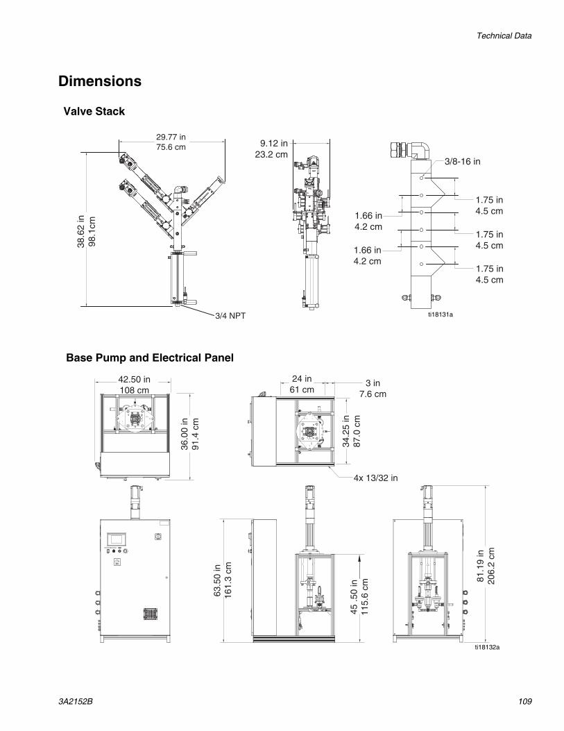
Technical Data
3A2152B 109
Dimensions
45 .5
0 in
115.
6 cm
63.5
0 in
161.
3 cm
81.1
9 in
206.
2 cm
36.0
0 in
91.4
cm
42.50 in108 cm
3 in7.6 cm
34.2
5 in
87.0
cm
24 in61 cm
4x 13/32 in
Valve Stack
Base Pump and Electrical Panel
ti18132a
29.77 in75.6 cm
38.6
2 in
98.1
cm
9.12 in23.2 cm
3/4 NPT
1.75 in4.5 cm
1.66 in4.2 cm
1.75 in4.5 cm
1.75 in4.5 cm1.66 in
4.2 cm
3/8-16 in
ti18131a

Accessories
110 3A2152B
Accessories24M126This kit is to add a third 1093 valve and necessary con-trols for the addition of color tinting.
24M127This kit adds pressure monitoring for the inhibitor valve, catalyst valve, and mixer outlet.
24M128This kit adds pressure monitoring for the third 1093 valve for color tinting.
NOTE: Kits 24M126 and 24M127 are required for the above kit to operate properly.

Accessories
3A2152B 111

All written and visual data contained in this document reflects the latest product information available at the time of publication. Graco reserves the right to make changes at any time without notice.
Original instructions. This manual contains English. MM 3A2152
Graco Headquarters: MinneapolisInternational Offices: Belgium, China, Japan, Korea
GRACO INC. AND SUBSIDIARIES • P.O. BOX 1441 • MINNEAPOLIS MN 55440-1441 • USACopyright 2011, Graco Inc. All Graco manufacturing locations are registered to ISO 9001.
www.graco.comRevision B, May 2015
Graco Standard WarrantyGraco warrants all equipment referenced in this document which is manufactured by Graco and bearing its name to be free from defects in material and workmanship on the date of sale to the original purchaser for use. With the exception of any special, extended, or limited warranty published by Graco, Graco will, for a period of twelve months from the date of sale, repair or replace any part of the equipment determined by Graco to be defective. This warranty applies only when the equipment is installed, operated and maintained in accordance with Graco’s written recommendations.
This warranty does not cover, and Graco shall not be liable for general wear and tear, or any malfunction, damage or wear caused by faulty installation, misapplication, abrasion, corrosion, inadequate or improper maintenance, negligence, accident, tampering, or substitution of non-Graco component parts. Nor shall Graco be liable for malfunction, damage or wear caused by the incompatibility of Graco equipment with structures, accessories, equipment or materials not supplied by Graco, or the improper design, manufacture, installation, operation or maintenance of structures, accessories, equipment or materials not supplied by Graco.
This warranty is conditioned upon the prepaid return of the equipment claimed to be defective to an authorized Graco distributor for verification of the claimed defect. If the claimed defect is verified, Graco will repair or replace free of charge any defective parts. The equipment will be returned to the original purchaser transportation prepaid. If inspection of the equipment does not disclose any defect in material or workmanship, repairs will be made at a reasonable charge, which charges may include the costs of parts, labor, and transportation.
THIS WARRANTY IS EXCLUSIVE, AND IS IN LIEU OF ANY OTHER WARRANTIES, EXPRESS OR IMPLIED, INCLUDING BUT NOT LIMITED TO WARRANTY OF MERCHANTABILITY OR WARRANTY OF FITNESS FOR A PARTICULAR PURPOSE.
Graco’s sole obligation and buyer’s sole remedy for any breach of warranty shall be as set forth above. The buyer agrees that no other remedy (including, but not limited to, incidental or consequential damages for lost profits, lost sales, injury to person or property, or any other incidental or consequential loss) shall be available. Any action for breach of warranty must be brought within two (2) years of the date of sale.
GRACO MAKES NO WARRANTY, AND DISCLAIMS ALL IMPLIED WARRANTIES OF MERCHANTABILITY AND FITNESS FOR A PARTICULAR PURPOSE, IN CONNECTION WITH ACCESSORIES, EQUIPMENT, MATERIALS OR COMPONENTS SOLD BUT NOT MANUFACTURED BY GRACO. These items sold, but not manufactured by Graco (such as electric motors, switches, hose, etc.), are subject to the warranty, if any, of their manufacturer. Graco will provide purchaser with reasonable assistance in making any claim for breach of these warranties.
In no event will Graco be liable for indirect, incidental, special or consequential damages resulting from Graco supplying equipment hereunder, or the furnishing, performance, or use of any products or other goods sold hereto, whether due to a breach of contract, breach of warranty, the negligence of Graco, or otherwise.
FOR GRACO CANADA CUSTOMERSThe Parties acknowledge that they have required that the present document, as well as all documents, notices and legal proceedings entered into, given or instituted pursuant hereto or relating directly or indirectly hereto, be drawn up in English. Les parties reconnaissent avoir convenu que la rédaction du présente document sera en Anglais, ainsi que tous documents, avis et procédures judiciaires exécutés, donnés ou intentés, à la suite de ou en rapport, directement ou indirectement, avec les procédures concernées.
Graco InformationFor the latest information about Graco products, visit www.graco.com.
For patent information, see www.graco.com/patents
TO PLACE AN ORDER, contact your Graco distributor or call to identify the nearest distributor.Phone: 612-623-6921 or Toll Free: 1-800-746-1334 Fax: 330-966-3006