+39)9 9HFWRU ,QYHUWHU - درنامهر: اتوماسیون صنعتی و...
82
Transcript of +39)9 9HFWRU ,QYHUWHU - درنامهر: اتوماسیون صنعتی و...


ONLY A COMPETENT ELECTRICIAN SHOULD CARRY OUT THEELECTRICAL INSTALLATION.
1 Internal Components and circuit boards (excepting the isolated I/O terminals) apply an electric current when HPVFV inverter is connected to the main voltage. This voltage isextremely dangerous and may cause death or severe injury if you come in contact with it.
2 When HPVFV is connected to the main power, the current is flowing in the motor connections (U, V, W), DC-Link (P, N) and Dynamic Brake Resistor Connections (R+,R-)even if the motor is not running.
3 If there is control power (220Vac) in HPVFV inverter, the current is flowing in the motor connections (U, V, W), DC-Link (P, N) and Dynamic Brake Resistor Connections (R+,R-).
This voltage is extremely dangerous and may cause death or severe injury if you come incontact with it.
4 The control I/O terminals are isolated from the main voltage but the relay outputs and other I/Os may have dangerous voltage connected even if the power is disconnected from theHPVFV.
5 HPVFV inverter has a large capacitive leakage current.
6 If a HPVFV inverter is used as a part of the machine, the machine manufacturer is obliged to take care that the inverter has a main switch and power fuse in the machine.
7 Spare parts can be delivered only by SOLCOM&HAPN Electric Co.,Ltd.
1.1 Warnings
1.2 Safety instructions
1 Do NOT make any connections when the HPVFV is connected to the main voltage.
2 Do NOT make any measurements when the HPVFVis connected to the main voltage.
3 After disconnecting the main power, wait until the cooling fan stops and the indicator ofkeypad goes out. Wait a further 5 minutes before doing any work on HPVFV connections. DoNOT open even the cover within this time.
4 Do NOT make any voltage withstand tests on any parts of the HPVFV inverter.
5 Disconnect motor cables from HPVFV before making any measurements on the motor cables or motors.
6 Do NOT touch the IC-circuits on the circuit boards. Static voltage discharge may destroy thecomponents.
7 Make sure that the cover of HPVFV inverter is closed before connecting the main voltage.
!
The ground terminal of HPVFV inverter has to
contact with ground wire.
Ground of HPVFV inverter prevents high voltage
accidents that are caused by switching.
Please be more cautious for the following
warning signs for user's safety.
= Dangerous Voltage
= General Warning!
Ground Warning Sign
1.3 Running the motor
!
1 Before running the motor, be cautious not to have any safety accident. Make sure that themotor is mounted properly. Check the parameters are set properly.
2 Maximum motor speed (frequency) should always be set according to the motor andmachine connected to the motor.
3 Before reversing the rotation of the motor shaft, make sure that this can be done safely.
004
1.SAFETY
003
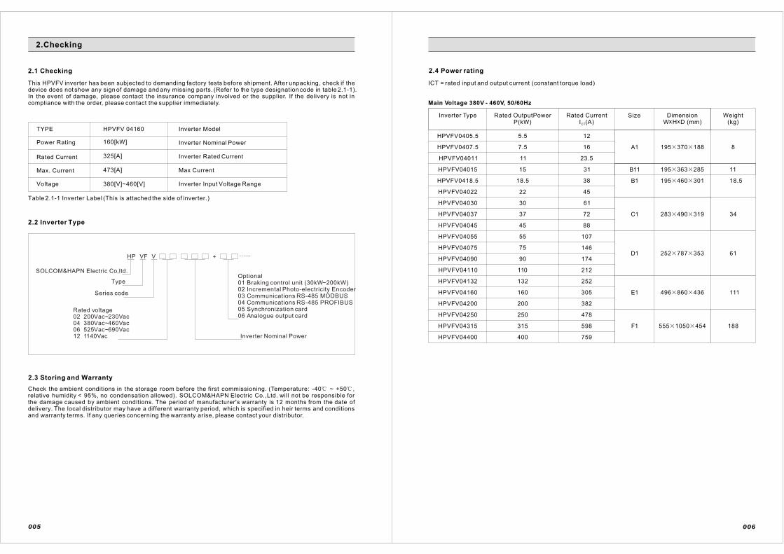
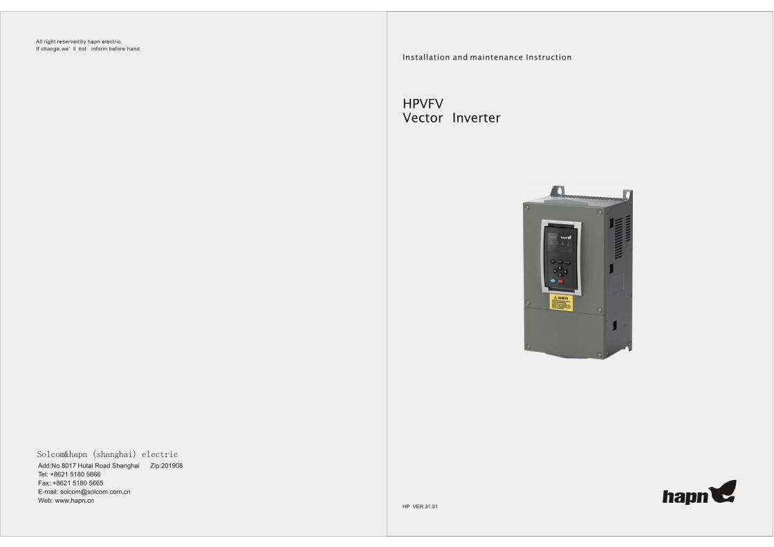
This HPVFV inverter has been subjected to demanding factory tests before shipment. After unpacking, check if thedevice does not show any sign of damage and any missing parts. (Refer to the type designation code in table 2.1-1). In the event of damage, please contact the insurance company involved or the supplier. If the delivery is not in compliance with the order, please contact the supplier immediately.
TYPE HPVFV 04160 Inverter Model
Power Rating 160[kW] Inverter Nominal Power
Rated Current 325[A] Inverter Rated Current
Max. Current 473[A] Max Current
Voltage 380[V]~460[V] Inverter Input Voltage Range
Table 2.1-1 Inverter Label (This is attached the side of inverter.)
2.2 Inverter Type
2.3 Storing and Warranty
Check the ambient conditions in the storage room before the first commissioning. (Temperature: -40 ~ +50 ,relative humidity < 95%, no condensation allowed). SOLCOM&HAPN Electric Co.,Ltd. will not be responsible for the damage caused by ambient conditions. The period of manufacturer's warranty is 12 months from the date ofdelivery. The local distributor may have a different warranty period, which is specified in heir terms and conditions and warranty terms. If any queries concerning the warranty arise, please contact your distributor.
HP VF V + ......
SOLCOM&HAPN Electric Co,ltd.
Type
Series code
Rated voltage02 200Vac~230Vac04 380Vac~460Vac06 525Vac~690Vac12 1140Vac Inverter Nominal Power
2.1 Checking
2.Checking
2.4 Power rating
ICT = rated input and output current (constant torque load)
HPVFV0405.5
Rated OutputPowerP(kW)
Rated CurrentI (A)CT
Size Dimensionx xW H D (mm)
Weight(kg)
HPVFV0407.5
HPVFV04011
HPVFV04015
HPVFV0418.5
HPVFV04022
HPVFV04030
HPVFV04037
HPVFV04045
HPVFV04055
HPVFV04075
HPVFV04090
HPVFV04110
HPVFV04132
HPVFV04160
HPVFV04200
HPVFV04250
HPVFV04315
HPVFV04400
Inverter Type
5.5
7.5
11
15
18.5
22
30
37
45
55
75
90
110
132
160
200
250
315
400
12
16
23.5
31
38
45
61
72
88
107
146
174
212
252
305
382
478
598
759
A1
B1
C1
D1
E1
195 370 188
195 460 301
283 490 319
252 787 353
496 860 436
8
18.5
34
61
111
F1 555 1050 454 188
006
Main Voltage 380V - 460V, 50/60Hz
005
Optional01 Braking control unit (30kW~200kW)02 Incremental Photo-electricity Encoder03 Communications RS-485 MODBUS04 Communications RS-485 PROFIBUS05 Synchronization card06 Analogue output card
B11 195 363 285 11

Main Voltage 660V - 690V, 50/60Hz
HPVFV06030
Rated OutputPowerP(kW)
Rated CurrentI (A)CT
Size Dimensionx xW H D (mm)
Weight(kg)
HPVFV06037
HPVFV06045
HPVFV06055
HPVFV06075
HPVFV06090
HPVFV06110
HPVFV06132
HPVFV06160
HPVFV06200
HPVFV06250
HPVFV06315
HPVFV06400
HPVFV06500
Inverter Type
30
37
45
55
75
90
110
132
160
200
250
315
400
500
35
42
50
61
84
100
122
145
175
220
275
343
435
544
A2250 650 336
527 1000 446
730 1400 470
250 850 341B2
C2
D2
Main Voltage 1140V, 50/60Hz
HPVFV12110
Rated OutputPowerP(kW)
Rated CurrentI (A)CT
Size Dimensionx xW H D (mm)
Weight(kg)
HPVFV12132
HPVFV12160
HPVFV12200
HPVFV12250
HPVFV12315
HPVFV12400
Inverter Type
110
132
160
200
250
315
400
73
82
103
128
160
202
255180
A3
B3
C3
366 906 442
650 1500 469
575 1000 418
HPVFV12560 560 320
*
007 008
HPVFV12630 630 375 ***
*
*
*
*
*
*
A21 284 490 306 24
!
Note:
Isolation testing is quite necessary if the motor has been standing idle for a long time, and make sure the resistance is not less than 5M
If the working voltage is out of nominal value, please connect with a matched transformer device.
If the attitude is higher than 1000m, the working output frequency will be reduced because ofthe physical cooling. The effect as figure 2.4-1:
100%
90%
80%
1000 2000 3000 4000 meter
Iout
Figure 2.4-1 Derating curve drauing of Frequency converter
The frame B1 is suitable for 15kW HPVFV inverter.The frame B11 is suitable for 15kW HPVFV scheme only,Please consult with supplier if requires 220V main voltage.

49
0
240
47
5
240
4- 7
283
302
319
78
77
64
4- 9210
252338210353
D1
C1
009 010
2.5 External Dimension
HPVFV inverter should be mounted in a vertical position on the wall or on the back plane of a cubicle. Follow therequirement for cooling. See chapter 3.2 for dimensions.
To ensure a safe installation, make sure that the mounting surface is relatively flat.
Fixing is done with four or more screws or bolts depending on the size of the unit. See Figure 2.5-1.
1704- 7
35
5
170195
37
0
160188
44
5
46
0
4- 7
150
150
195
290
301
A1
B1

A2
B2
011 012
220 4- 9
63
0
65
0
336
320220
250
220 4- 9
85
0
83
0
220
81
5
325
341
250
14
83
0
400
86
0
400
496
436
420
4704- 13
470
10
18
454
10
50
555
E1
F1
Figure 2.5-1(a) Mounting dimensions

A3
B3
013 014
14
8.8
55
5.6
172.6
329.75366
90
6
310.8
442
426
91.5
90
2
88
2.5
Min
.9.5
57.525157.5
4704- 13
96
72
10
00
2
418
470
575
C2
D2
Figure 2.5-1(b) Mounting dimensions
8- 13
220
470
13
65
220 220 220
14
00
220 220
730
456
4- 14420
420
97
2
446
430
527
10
00

C3
Figure 2.5-1(c) Mounting dimensions
650280 28012
31
15
00
14
60
469453
12280 280
18
A21
B11
284
240
49
0
47
5
306
285.4195
168
R3.5
36
33
51
7R3.5
270
015 016

2.6 Usage of auxiliary equipment
When using a HPVFV Inverter, it is recommended to use right auxiliary equipments. If the auxiliary equipments arenot right for HPVFV inverter, it can cause damage to the inverter. Therefore, follow the recommendedspecifications for configuration.
017
Input VoltageVin
3 Phase 200Vac~230Vac, 380Vac~460Vac, 660Vac~690Vac3 Phase 1200Vac
Input Frequency 50Hz~60Hz ( 10%)
10%
Connection to theMain
Don't turn on or off the inverter more than 1 times within1 min.
Output Voltage 0 ~95% of Vin
C o n t i n u o u sOutput current
Ict : ambient max. +40Over load 1.5xIct (1min./10min.)Ivt : ambient max. +40 ,not Over load
Starting Torque150%~200%( 0.5Hz) in Sensorless V/F Control150% ~200% (0Hz) in Sensorless Vector Control
OutputFrequency/speed
Sensorless : 0.0~300.0[Hz] / 0.0~3000.0[Hz]Sensored : 0~8000 [rpm]
Frequency/speedresolution
Sensorless V/F : 0.01Hz / 0.1HzSensorless & Sensored Vector : 1[rpm]
Control Method
SwitchingFrequency
Sensorless V/F Frequency ControlSensorless V/F Speed ControlSensorless Vector Speed ControlSensorless Torque ControlSensored Vector Speed ControlSensored Torque Control
AnalogInput
Keypad
Resolution 10bit, accuracy 0.1%
Resolution 0.01Hz / 0.1Hz
Field weakening point
Auto Tuning
Acceleration Time
V/F Control 0.5~3000.0[sec]Sensorless & Sensored Vector Control-0.00~3000.00[sec]
Deceleration Time
V/F Control 0.5~3000.0[sec]Sensorless & Sensored Vector Control-0.00~3000.00[sec]
SurroundingTemperature -10 ~ +40
Relative Humidity 90%, no condensation allowed
MainConnection
Rated Output
ControlCharacteristics
EnvironmentalLimits
Frequency reference
2.7 Specifications
018
1.0~5.0[kHz]
1.0~2.0[kHz]
1.2[kHz]below
400V
200V
690V
400V
200V
690V
400V
690V
1140V
5.5kW~90kW
5.5kW~45kW
30kW~55kW
110kW~200kW
55kW~90kW
55kW~250kW
250kW~
315kW~
110kW~
3F 45~66Hz
220Vac/380~460Va
c
Input source
Should be used within rated source
indicated on the manual.
Earth leakage circuit breaker (ELCB)
When the Main Power in On, Very big
inrush current can be occurred, So, You
should be care when you choose the
spec. about this.
Magnetic contactor
You should not run or stop the Driver
using this contactor.
Fuse
Use the fuse to protect the Driver
AC reactor
It improves the power factor and reduces
the ripple current of inverter Capacitors.
RFI ( radio frequency interference ) filter
RFI reduce the noise copied at Input source
Line, and can protect the malfunction of
equipment.
Line connection of inverter
Inverter can be damaged because wrong
connection. Signal Line should separate from Power
Line and should be used the shield cables.
Output of inverter
Do not Connect the magnetic Contactor, Phase
advance Capacitor, Surge Absorber at output of
Inverter.
Place to install
Life time of Inverter is influenced by ambient temperature.
Inverter should be installed at the place is well ventilated.
You should not install at a airtight room.
5.5
7.5
11
15
18.5
22
30
37
45
55
75
Power kWVentilation
3quantity m /h
Power kWVentilation
3quantity m /h
26.5
36
53
72.2
89
105.9
144.5
178.2
216.7
264.9
361.2
90
110
132
160
200
250
315
400
500
560
433.4
529.8
635.7
770.6
963.2
1204
1517.1
1926.4
2408
2697
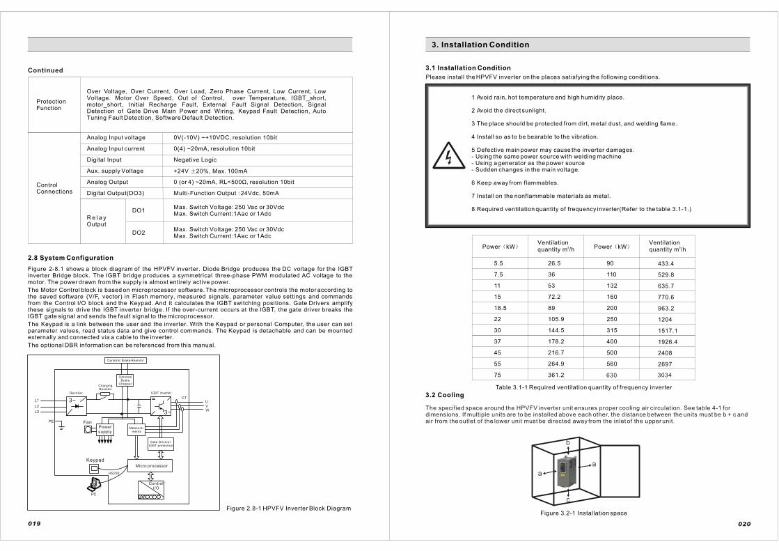
1 Avoid rain, hot temperature and high humidity place.
2 Avoid the direct sunlight.
3 The place should be protected from dirt, metal dust, and welding flame.
4 Install so as to be bearable to the vibration.
5 Defective main power may cause the inverter damages.- Using the same power source with welding machine- Using a generator as the power source- Sudden changes in the main voltage.
6 Keep away from flammables.
7 Install on the nonflammable materials as metal.
8 Required ventilation quantity of frequency inverter(Refer to the table 3.1-1.)
Over Voltage, Over Current, Over Load, Zero Phase Current, Low Current, Low Voltage. Motor Over Speed, Out of Control, over Temperature, IGBT_short, motor_short, Initial Recharge Fault, External Fault Signal Detection, Signal Detection of Gate Drive Main Power and Wiring, Keypad Fault Detection, AutoTuning Fault Detection, Software Default Detection.
ProtectionFunction
ControlConnections
0V(-10V) ~+10VDC, resolution 10bit
0(4) ~20mA, resolution 10bit
Negative Logic
+24V 20%, Max. 100mA
0 (or 4) ~20mA, RL<500Ù, resolution 10bit
Multi-Function Output : 24Vdc, 50mA
Analog Input voltage
Analog Input current
Digital Input
Aux. supply Voltage
Analog Output
Digital Output(DO3)
Max. Switch Voltage: 250 Vac or 30VdcMax. Switch Current:1Aac or 1Adc
Max. Switch Voltage: 250 Vac or 30VdcMax. Switch Current:1Aac or 1Adc
DO1
DO2
R e l a yOutput
2.8 System Configuration
Figure 2-8.1 shows a block diagram of the HPVFV inverter. Diode Bridge produces the DC voltage for the IGBTinverter Bridge block. The IGBT bridge produces a symmetrical three-phase PWM modulated AC voltage to the motor. The power drawn from the supply is almost entirely active power.
The Motor Control block is based on microprocessor software. The microprocessor controls the motor according to the saved software (V/F, vector) in Flash memory, measured signals, parameter value settings and commands from the Control I/O block and the Keypad. And it calculates the IGBT switching positions. Gate Drivers amplify these signals to drive the IGBT inverter bridge. If the over-current occurs at the IGBT, the gate driver breaks theIGBT gate signal and sends the fault signal to the microprocessor.
The Keypad is a link between the user and the inverter. With the Keypad or personal Computer, the user can set parameter values, read status data and give control commands. The Keypad is detachable and can be mounted externally and connected via a cable to the inverter.
The optional DBR information can be referenced from this manual.
Figure 2.8-1 HPVFV Inverter Block Diagram
019
Continued 3.1 Installation Condition
Please install the HPVFV inverter on the places satisfying the following conditions.
3. Installation Condition
Dynamic Brake Resistor
OptionalBrake
Chopper
IGBT inverter
ChargingResistor
Rectifier
FanPowersupply
Keypad
ControlI/O
Gate Drivers+IGBT protection
Measure-ments
3.2 Cooling
The specified space around the HPVFV inverter unit ensures proper cooling air circulation. See table 4-1 for dimensions. If multiple units are to be installed above each other, the distance between the units must be b + c and air from the outlet of the lower unit must be directed away from the inlet of the upper unit.
020
Figure 3.2-1 Installation space
Table 3.1-1 Required ventilation quantity of frequency inverter
630 3034

3.3 Installation of keypad on the external panel
Figure 3.3-1 Installation of keypad on the external panel
When installing the HPVFV Keypad on the external panel, refer to the figure 3.3-1. First, make holes on the spot of the panel as shown in the figure 3.3-1. Then, install the keypad plate with bolts. The keypad that is installed on theexternal panel is connected by RJ11 serial cable, which is 1:1 connection. Refer to the figure 3.3-1.
021 022
4.WIRING
RJ11Connector (phone line connector)
1:1 connection
HPVFV-keypadcommunincationcable
Attach thekeypadholder afterinstallation
keypad
screw size
External panel
Keypad holder
Keypad
RJ11connector
HPVFV-Keypadcommunicationcable
Install the keypad holderwith bolts on the panel
1 Connect the ground cable surely.If multiple units are to be installed, Do not loop the ground cables.
2 Only a competent electrician should carry out the wiring
3 Make sure that the input main voltage is switched off.
4 Do NOT connect AC power source to the output terminals (U, V, W).
5 In the case of installing an earth leakage breaker at the input (L1, L2,L3), Make inquiries to a competent electrician for the set-up of leakage current.
6 Power cables, the earth leakage breaker and a Magnetic contactor should be used with therated capacity.
7 Attach surge filters to the Magnetic contactors that are installed around inverter.
8 Installing Static Condenser or Surge Suppressor on the output of Inverter is prohibited. Incase of installed already, please remove.
9 Do NOT run or stop the inverter and/or the electric motor connected to it using Magnetic contactors [located at the main power input(L1,L2,L3) and/or output(U,V,W)]
10 Fasten the terminal screws to the relevant torque value and make sure that there are not loose terminals.
11 The length of wire connected output lines to motor should be within 50m. In case of multiconnection with several motors by only one Inverter, the length of wire between Inverter andmotors should be within 50m. If the length of all wires connected to each device is inevitably over 50m, install AC Reactor between output lines ofInverter and motors.
12 When several motors are running by one inverter, install a thermal relay for each.
13 Use twisted and shielded cable for signal cables. For encoder signal cables, use the shielded cable containing 6 wires in the cable. The wires in the cable should be twisted and shielded by twos. Although the encoder signal cables have a good quality, they could be affected by surrounding noises during wiring. It needs a special attention.
14 The signal cables must be isolated from the power cables. For an unavoidable case, installperpendicular to each other as shown below.
Signal Cable Power Cable
maintainover 10cm
maintainover 10cm
(a)Good
Inverter#1
Inverter#2
Inverter#3
Inverter#1
Inverter#2
Inverter#3
(a)Not good
SIZE
A1
B1
A2
B2
E2
F1/C2/D2/C3
Dimension(mm)
a
20
20
30
75
250
250
a2
10
10
10
75
75
75
b
150
150
160
300
300
300
C
50
60
80
100
----
----
Table 3.2-1 Installation space dimensiona2 = distance from the inverter unit to other inverter unit
4.1Cautions in Wiring
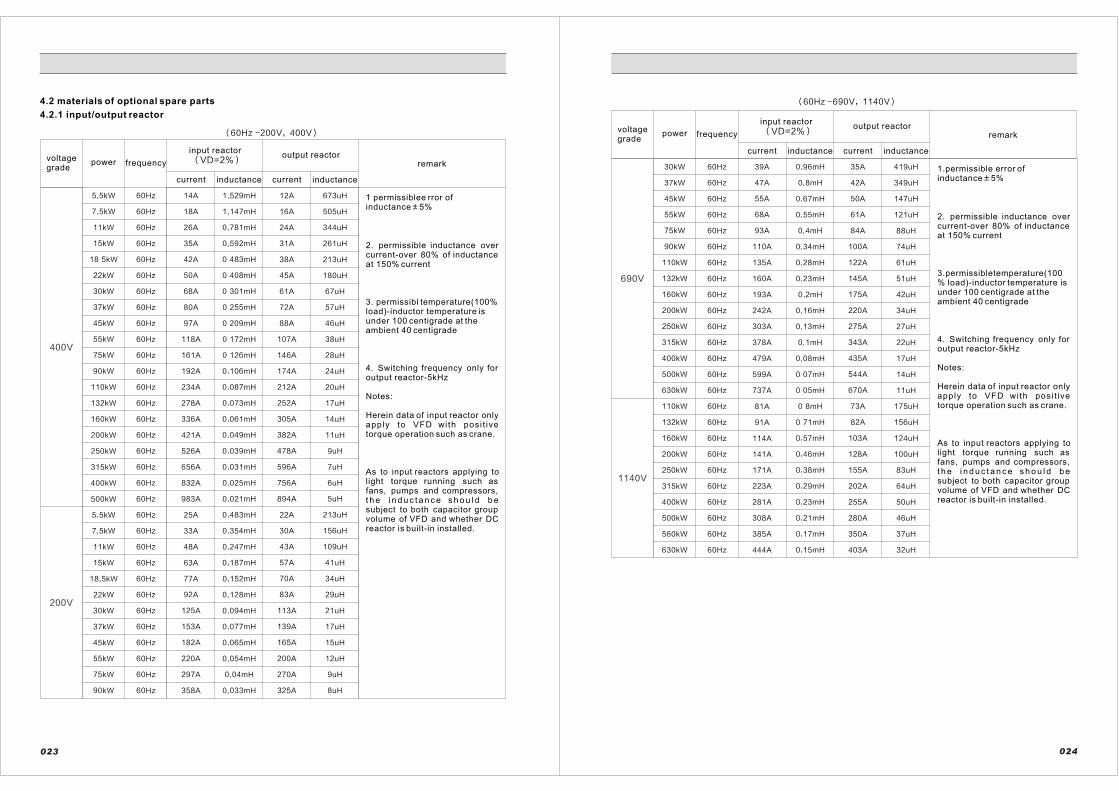
1 permissiblee rror ofinductance 5%
2. permissible inductance overcurrent-over 80% of inductance at 150% current
3. permissibl temperature(100% load)-inductor temperature is under 100 centigrade at the ambient 40 centigrade
4. Switching frequency only for output reactor-5kHz
Notes:
Herein data of input reactor onlyapply to VFD with posi t ive torque operation such as crane.
As to input reactors applying tolight torque running such as fans, pumps and compressors, t h e i n d u c t a n c e s h o u l d b esubject to both capacitor group volume of VFD and whether DCreactor is built-in installed.
4.2 materials of optional spare parts
4.2.1 input/output reactor
voltagegrade
power frequency
input reactoroutput reactor
current inductance current inductance
remark
voltagegrade
power frequency
input reactoroutput reactor
current inductance current inductance
remark
1.permissible error of inductance 5%
2. permissible inductance overcurrent-over 80% of inductance at 150% current
3.permissibletemperature(100% load)-inductor temperature isunder 100 centigrade at the ambient 40 centigrade
4. Switching frequency only for output reactor-5kHz
Notes:
Herein data of input reactor onlyapply to VFD with posi t ive torque operation such as crane.
As to input reactors applying tolight torque running such as fans, pumps and compressors, t h e i n d u c t a n c e s h o u l d b esubject to both capacitor group volume of VFD and whether DCreactor is built-in installed.
023 024

voltagegrade
power frequency
input reactoroutput reactor
current inductance current inductance
remark
1.permissible errorofinductance 5%
2. permissible inductanceover current-over 80% ofinductance at 150% current
3. Permissibletemperature(100% load)-inductor temperature is under100 centigrade at the ambient 40 centigrade
4. Switching frequency onlyfor output reactor-5kHz
Notes:
Herein data of input reactor only apply to VFD with positivetorque operat ion such ascrane.
As to input reactors applying to light torque running such asfans, pumps and compressors, the inductance should be
voltagegrade
power frequency
input reactoroutput reactor
current inductance current inductance
remark
1.permissible error of inductance 5%
2. permissible inductance overcurrent-over 80% of inductance at 150% current
3. permissibletemperature(100% load)-inductor temperature is under100 centigrade at the ambient 40 centigrade
4. Switching frequency only for output reactor-5kHz
Notes:
Herein data of input reactor onlyapply to VFD with posi t ive torque operation such as crane.
As to input reactors applying tolight torque running such as fans, pumps and compressors, t h e i n d u c t a n c e s h o u l d b esubject to both capacitor group volume of VFD and whether DCreactor is built-in installed.
025 026

Frame K3/K3A
*) refer to chapter 2.4 for power rating
of each frame
1
2
3
4
5
6
7
8
9
10
11
12
13
14
15
16
18
17
19
20
21
22
23
24
25
26
Vin: Voltage input for reference
Iin: Current input for reference
0~20mA or 4~20mA
Positive of relay is for 20
Negetive of relay is fo
*)Do not connect to braking
resistor on the terminal-N
*)After removing busbar connected to P1 and P2,
available to use with connecting DC reactor
L1 L2 L3 U V W P1 P2 R N
DBR
(optional)IM
(recommendation)
Fuse
Ground
10Vref COM.
+10Vref : 10Vdc
supply terminal
Vin1/Iin1+
Iin1-
Vin2/Iin2+
Iin2-
DI:1
DI:2
DI:3
DI:4
DI:5
DI:6
DI:7
DI:8
COM: common for I/O
COM: common for I/O
Shielded cable
DO1.A
DO1.B
DO1.C
DO2.A
DO2.C
DO2.B
AC 1A/250V
DC 1A/30V
AC 1A/250V
DC 1A/30V
24Vdc,50mA
Shielded
cable
COM/Iout-
0(4)~20m
A
Iout+
24out
DO 3
* AC reactor and RFI filter on the input lines (L1,L2,L3) are optional items.
* DC reactor connected to P1 and P2 on K3 inverter are optional items.
* Output reactor on the output lines (U,V,W) are optional items.
*Don t́ connect DBR to terminal N.
*Installing fuse is recommended when breaking resistor be connected between terminal
and breaking resistor.
1k~10k 0.5w
4.2.2 Dynamic Brake Resistor
See table 4.2-1 for the standard brake resistor of HPVFV.Please, ask the factory or the head office for details on recommended DBR for vertical loads and equipments that have a high frequency in use.
Caution!
1) Ask the factory for the detail of DBR information
2) Ask the head office for the case of 600VV and 1140V class inverter
3) The above values are calculated by based on following information: Braking torque:100%, Using rating:5%ED
4) Installing fuse is recommended when HPVFV Inverter and breaking resistor are connected.
027
4.3 Wiring Diagram
Figure 4.3-1 HPVFVinverter FrameA1
028
Frame A1

Figure 4.3-2 HPVFV inverter FrameB1
029
Figure 4.3-3 HPVFV inverter FrameC1
030
Frame B1
1
2
3
4
5
6
7
8
9
10
11
12
13
14
15
16
18
17
19
20
21
22
23
24
25
26
L1 L2 L3 U V WR- *)N
IM
Vin1/Iin1+
Iin1-
Vin2/Iin2+
Iin2-
DI:1
DI:2
DI:3
DI:4
DI:5
DI:6
DI:7
DI:8
COM: common I/O
DO1.A
DO1.B
DO1.C
DO2.A
DO2.C
DO2.B
AC 1A/250V
DC 1A/30V
AC 1A/250V
DC 1A/30V
24Vdc,50mA
COM/Iout-
0(4)~20mA
Iout+
24out
DO 3
1k~10k 0.5w
P/R+ E
* AC reactor and RFI filter on the input lines (L1,L2,L3) are optional items.
* Output reactor on the output lines (U,V,W) are optional items.
* Don t́ connect DBR to terminaminal N .
COM: common I/O
Vin: Voltage input for reference
Iin: Current input for reference
0~20mA or 4~20mA
Positive of relay is for 20
Negetive of relay is for 19
*) refer to chapter 2.4 for power rating
of each frame10Vref COM.
+10Vref : 10Vdc
supply terminal
Shielded
cable
Shielded
cable
DBR
(optional)
Fuse
Ground
Frame C1
1
2
3
4
5
6
7
8
9
10
11
12
13
14
15
16
18
17
19
20
21
22
23
24
25
26
L1 L2 L3 U V W R-
IM
Vin1/Iin1+
Iin1-
Vin2/Iin2+
Iin2-
DI:1
DI:2
DI:3
DI:4
DI:5
DI:6
DI:7
DI:8
DO1.A
DO1.B
DO1.C
DO2.A
DO2.C
DO2.B
AC 1A/250V
DC 1A/30V
AC 1A/250V
DC 1A/30V
24Vdc,50mA
COM/Iout-
0(4)~20mA
Iout+
24out
DO 3
1k~10k 0.5w
P/R+
*) refer to chapter 2.4 for power rating
of each frame
Vin: Voltage input for reference
Iin: Current input for reference
0~20mA or 4~20mA
Positive of relay is for 20
Negetive of relay is for 19
DBR
(optional)
Fuse
Ground
10Vref COM.
+10Vref : 10Vdc
supply terminal
COM: common for I/O
COM: common for I/O
Shielded cable
* AC reactor and RFI filter on the input lines (L1,L2,L3) are optional items.
* Output reactor on the output lines (U,V,W) are optional items.
*Installing fuse is recommended when breaking resistor be connected between terminal
and breaking resistor
Shielded
cable

Figure 4.3-4 HPVFV inverter Frame A2/D1/E1/B2/A3
Frame A2/D1/A3/B21
2
3
4
5
6
7
8
9
10
11
12
13
14
15
16
18
17
19
20
21
22
23
24
25
26
U V W
IM
Vin1/Iin1+
Iin1-
Vin2/Iin2+
Iin2-
DI:1
DI:2
DI:3
DI:4
DI:5
DI:6
DI:7
DI:8
DO1.A
DO1.B
DO1.C
DO2.A
DO2.C
D02.B
AC 1A/250V
DC 1A/30V
AC 1A/250V
DC 1A/30V
24Vdc,50mA
COM/Iout-
0(4)~20mA
Iout+
24out
DO 3
L1 L2 L3Charging resistor
DC+ DC+
PE
R+ R-
*) refer to chapter 2.4 for power rating
of each frame
Vin: Voltage input for reference
Iin: Current input for reference
0~20mA or 4~20mA
Positive of relay is for 20
Negetive of relay is for 19
DBR
(optional)
Fuse
Ground
10Vref COM.
+10Vref : 10Vdc
supply terminal
COM: common for I/O
COM: common for I/O
Shielded
cable
* AC reactor and RFI filter on the input lines (L1,L2,L3) are optional items.
* Output reactor on the output lines (U,V,W) are optional items.
* Do not connect DBR to terminal N.
*Installing fuse is recommended when breaking resistor be connected between terminal
and breaking resistor
* Need to supply 220V control VoItaje for frame A3 inverters.
Shielded cable
Brake chopper
(optional)
031
Figure 4.3-6 HPVFV inverter Frame F1/C2/D2/C3
Frame F1/C2/D2/C3
1
2
3
4
5
6
7
8
9
10
11
12
13
14
15
16
18
17
19
20
21
22
23
24
25
26
U V W
IM
Vin1/Iin1+
Iin1-
Vin2/Iin2+
Iin2-
DI:1
DI:2
DI:3
DI:4
DI:5
DI:6
DI:7
DI:8
DO1.A
DO1.B
DO1.C
DO2.A
DO2.C
D02.B
AC 1A/250V
DC 1A/30V
AC 1A/250V
DC 1A/30V
24Vdc,50mA
COM/Iout-
0(4)~20mA
Iout+
24out
DO 3
L1 L2 L3
N-
P+
DC+ DC+
34
35
*220V
Fan power
* AC reactor and RFI filter on the input lines (L1,L2,L3) are optional items.
* Output reactor on the output lines (U,V,W) are optional items.
*Installing fuse is recommended when breaking resistor be connected between terminal
and breaking resistor
*No need to supply 220V control voltage for frame C2/D2 inverters
Brake chopper
(optional)
(recommendation)
Fuse
DBR
(optional)
Vin: Voltage input for reference
Iin: Current input for reference
0~20mA or 4~20mA
Positive of relay is for 20
Negetive of relay is for 19
+10Vref : 10Vdc
supply terminal
COM: common for I/O
COM: common for I/O
Shielded cable
Shielded cable
10Vref COM.
Charging resister
032

4.4 Power Connections
*F1 Control terminal connections
Use heat-resistant cables (600V, +70 or higher). The Power cables and the fuses have to be dimensioned in accordance with the rated output current of the unit and the size of the cables. The minimum dimensions for theCu-cables and corresponding fuses are given in the table 4.4-1.The fuses have been selected so that they will also function as an overload protection for the cables. If 3 or more cables are used in parallel, Please be cautious for that every cable must have its own overload protection. These instructions concern the cases about that there is one motor and one cable connection from the inverter to the motor. For other cases, ask the factory for more information.
033
5.5 kW
7.5 kW
11 kW
15 kW
18.5 kW
22 kW
30 kW
37 kW
45 kW
55 kW
75 kW
90 kW
110 kW
132 kW
160 kW
200 kW
250 kW
315 kW
400 kW
30 kW
37 kW
45 kW
55 kW
75 kW
90 kW
110 kW
132 kW
160 kW
200 kW
250 kW
315 kW
400 kW
500 kW
20
30
35
45
60
70
100
100
100
150
200
250
300
400
400
500
630
*
*
50
50
63
63
100
100
125
160
200
250
*
*
*
*
4 / 4
6 / 6
16 / 10
16 / 10
16 / 10
16 / 10
25 / 16
25 / 16
50 / 16
50 / 25
70 / 25
95 / 35
95 / 35
95 / 35
2*(95 / 50 )
2*(95 / 50 )
*
*
70 / 25
10/ 10
10/ 10
16/ 16
16/ 16
35/ 16
35/ 16
50 / 25
70/ 35
50 / 95
150/ 70
*
*
*
*
TYPEFUSE[A]
Cu-CableIn.output/GND[mm2]
4.4-1 recommended motor and power cables and fuse ratings * ask manufacturers
400V
690V
1200V
110 kW
132 kW
*
*
*
*
160 kW
200 kW
250 kW
*
*
*
*
*
*
315 kW
400 kW
560 kW
*
*
*
*
*
*
034
CONTROL TERMINAL WIRING - F1
TerminalNO.
7
8
9
10
11
12
13
14
DI.01
DI.02
DI.03
DI.04
DI.Com
DI.05
DI.07
DI.06
AO1.P
NO.
15
16
17
18
19
20
Terminal
DI.08
DI.Com
AO1.N/DI.Com
AO1.P
DO3.24V
21
22
23
24
25
26
DO1.A
DO1.B
DO1.C
DO2.A
DO2.B
DO2.C
NO. TerminalTerminalNO.
1
2
3
4
5
6
Vref.Com
Vref.+10v
AI1.P
AI1.N
AI2.P
AI2.N

4.4.1 Installation Instructions
4.4.2 Cable and Motor insulation check
Order Check items
CHECK 1
Motor Cable Insulation Check
Disconnect the motor cables from the output terminals (U, V and W).Measure the insulation resistance of the motor cable between each phase conductor, and measure between each phase conductor and the protective groundconductor. The insulation resistance must be 1MÙ.
Main power cable Insulation Check
Disconnect the main power cables from the terminals L1, L2 and L3.Measure the insulation resistance of the main power cables between each phaseconductor, and measure between each phase conductor and the protective groundconductor. The insulation resistance must be 1MÙ.
Motor Insulation Check
Disconnect the motor cables from the motor. Measure the insulation resistance of each motor winding. The measurement voltage has to be at least equal to the main voltage but not exceed 1000V. The insulationresistance must be 1MÙ.
CHECK 2
CHECK 3
035
4.5 Control Connections
Basic connection diagram is shown in figure 4.3-1~ 4.3-6
4.5.1 Control cable2
The control cables should be at least 0.5 mm shielded cables. The maximum wire size fitting in the terminals is 2.5 2
mm .
4.5.2 Encoder cable
For the encoder cable, use the shielded cable containing 6 wires. The wires in the cable should be shielded by two each. See Figure 4.6-1. Pay attention to the cable installation in order to isolate from the main power cable andnoise environment.
Figure 4.5-1 Encoder Cable
036
1 Place the motor cables further away from the other cables.- Avoid long parallel runs with other signal cables.- The maximum motor cable is 50m.- The motor cable should cross other signal cables at a right angle of 90 degrees if inevitable.
2 See chapter 4.5.2 for cable insulation check.
3Connecting cables:-Remove the cover of the motor and power cables.-Open the cover of HPVFV inverter-Connect the motor and control cables to the correct terminals. (refer to Figure 4.4-1~4.3-6)-Check if control cables do not make any contacts with electrical components in the device.-Connect the brake resistor cable (optional).-Ensure the earth cable is connected to the terminal of the inverter and motor.-Connect the separate shield of power cables to motor, supply panel and the protective earth of the inverter.-Ensure that the external control cable or internal wirings are not trapped between the cover and the body of the unit.

M6 Password
[0] Operation Status
[2] Drive Information
Group [0]~[26]
Main MENU M0 Operation
M1 Drive Monitor
M2 Parameter Edit
M3 Auto Tuning
M4 Fault Record
M5 Initialize
[0] Motor Speed [1] Output Frequency
[2] Dc Link Voltage [3] Motor Current
[4] Output Voltage [5] Auctual Torque
[6] Torque Current [7] Flux Current
[8] Input Power [9] Output Power
[10] PID Reference [11] PID Feedback
[12] PID Error [13] Temperature
[0] Digital Input [1] Digital Output
[2] Analog Input 1 [3] Analog Input2
[4] Analog Output
[0] Motor Selection [1] Control Method
[2] RUN/STOP Scr. [3] Reference Metheod
[4] Drive Power [5] Drive Voltage
[6] Option Card [7] Software Version
[8] Software Option
[X.11] Motor Voltage
X.9] Dc Link Voltage
[X.7] Temperature
[X.5] Motor Speed
[X.3] Control Method
X.1] Fault Code [X.2] Motor Selection
[X.4] Speed Command
[X.6] Frequency
[X.8] Actual Torque
[X.10] Motor Current
[0] Program Control [1] Control Setup [M1]
[2] Control Setup [M2] [3] Ref. Setup [M1]
[4] Ref. Setup [M2] [5] Protection
[6] Analog Input Setup [7] PID Control
[8] Digital Input Setup [9] Multi Step Ref.[M1]
[10] Multi Step Ref.[M2] [11] Analog Output Cfg.
[12] Digital Output Set. [13] Motor Brake Control
[14] Auto Tuning Cfg. [15] V/F Control [M1]
[16] V/F Control [M2] [17] S/L Vector [M1]
[18] S/L Vector [M2] [19] Vector Cntl [M1]
[20] Vector Cntl [M2] [21] Motor 1 Constant
[22] Motor 2 Constant [23] Common Control
[24] Monitor setup
[0] Local/Remote
[1] Direction Change
[2] Speed Reference
[3] Frequency Reference
[4] Torque Reference
[5] PID Reference
Record[y]
X =1~9
[0] Drive Calibration
[1] Motor Turning
[2] Speed Turning
[0] Clear Fault List
[1] System Reset
[2] Parameter
[0] Access
[1] Admission
[2] Password Change
[1] Terminal I/O
4.5.3 Control I/O Terminal Signals
No Terminal Function
1 Vref.COM Voltage Reference Ground
Vref.+10V +10V Voltage supply Terminal2
3 AI 1 . P
AI 1 . N4
Vref (+) input / Iref (+) input
Iref (-) input
5 AI 2 . P Vref (+)input / Iref (+)input
6 AI 2 . N Iref (-) input
7 DI 1 Digital Input 1
8 DI 2 Digital Input 2
9 DI 3 Digital Input 3
10 DI 4 Digital Input 4
11 DI. COM Digital Input Ground
12 Digital Input 5DI 5
13 DI 6 Digital Input 6
14 DI 7 Digital Input 7
15 DI 8 Digital Input 8
16
17
18
19
20
21
22
DI. COM
AO 1.N
AO 1.P
DO3.OC
24Vout
DO1.B
DO1.A
COM Digital Input Ground
Analog Output (-) / DI.COM
Analog Output (+)
Digital output 3
24V supply voltage
Digital output 1 (a-contactor)
Digital output 1 (b-contactor)
Specification
+10V output
GND for Voltage reference signal
Users can set up (refer to the parameter table)
Users can set up(refer to the parameter table)
Ground for Digital Input
Users can set up(refer to the parameter table)
Users can set up(refer to the parameter table)
Users can set up(refer to the parameter table)
Users can set up(refer to the parameter table)
Ground for Digital Input
Open Collector output : Users can set up
+24V output(DO3. for Open Collector output terminal)
Analog Output (Users can set up)0~20mA / 4~20mA
Forward Operation (Forward Run)
Reverse Operation (Reverse Run)
Users canset up
Voltage 2 / Current 2 Reference SignalSignal range : 0(-10VDC) ~ +10VDCSignal range : 0(4) ~ 20mA
Voltage 1 / Current 1 Reference Input SignalSignal range : 0(-10VDC) ~ +10VDCSignal range : 0(4) ~ 20mA
23
24
25
26
DO1.C
DO2.A
DO2.B
DO2.C
Digital output 1 (c-contactor)
Digital output 2 (a-contactor)
Digital output 2 (b-contactor)
Digital output 2 (c-contactor)
Relay Output (Users can set up)
Relay Output (Users can set up)
Table 4.6-1 Description of control terminal
037
5. Composition of Operation Main Menu
Figure 5-1 Composition of Main Menu for HPVFV inverter
038

6.1 Keypad description
The keypad of HPVFV inverter is composed with 9 keys, (ESC, ENTER, RUN, STOP, MENU, Left, Right, UP and Down scroll key). Users can set up parameters and monitor the operation status and start/ stop the motor with keypad, etc. See figure 6.1-1.
LCD Display :
If there are no work for certain
time , the backlight will be off.
And it will be automatically
turned on when it starts
working. The default value is
30 minutes.
ESC Key :
Move to upper menu. Reset
when a Fault occurs.
L/R scroll key :
When users change parameters,
these keys move the digits of
parameter values.
RUN Key :
When running the motor with
keypad.
MENU Key :
When a fault occurs, this is for
moving to the last item, this
moves to the inverter status
monitor.(toggle button)
ENTER key :
When moving to the lower menu
or Executing
U/D scroll key :
When moving to the Menu page,
Monitor item and parameter items
STOP Key :
When stopping the motor with
Keypad
Figure 6.1-1 KEYPAD
6.2 Keypad operation
The data of KEYPAD is composed with Main Menu and low-level sub-Menu as Figure 6.2-1. Push the button, ,
to move from Main Menu to low-level sub-menu. And Push thebutton, , to escape from low-level sub-Menu to
Main Menu. Use the buttons, ,to Increase or decrease the data value. Use the button, , to move
cursors when setting-up parameters. When monitoring/checking the status of inverter and listing the Error/Fault,
use the button, . When operating by KEYPAD, users can start/stop the motor with the buttons, and .
The detailed usage can be referred from chapter 6.2.1 ~ 6.2.9.
039
6.Keypad
Main Menu Sub Menu 1 Sub Menu 2
[0] Local / Remote
[LOCAL]]Main Menu Page
M0 Operation
Main Menu Page
M1 Drive Monitor
M1 Drive Monitor
[0] OP Status[0] Motor Speed
0 rpm
M1 Drive Monitor
[1] Terminal I/O[0] DI [8. . . . . . .1]
00000000
[0] Motor Sel
Motor (1)
M1 Drive Monitor
[2] Drive Info
Main Menu Page
M2 Parameter EdtM2 Parameter Edt
G0 Program Cntl
P0.1 PG_Key1
[0] Standard I
Motor Tuning
Complete !
[1.1] Fault Code
3
[0] Clr FaultList
Completed !
M6 Password
[0] Access = [L0]
M5 Initialize
[0] Clr FaultList
Main Menu Page
M6 Password
Main Menu Page
M5 Initialize
Main Menu Page
M4 Fault RecordTotal Fault = 3
Record (1)
M3 Auto Tuning
[0] Motor TuningMain Menu Page
M3 Auto Tuning
Figure 6.2-1 KEYPAD usage
040

6.2.1 Main Menu Page[0] Operation
In M0 operation page, when operating motor that is connected to the HPVFV inverter with keypad without any I/O
terminal connections, it allows to set up the rotating direction, speed, frequency, torque reference and PID
reference. Refer to Figure 6.2-2. When operating (start or stop) the motor by KEYPAD or [0] Local/Remote has to
be set to [Local] , use the button, . And Parameter P3.0 and P3.1 have to be set for KEYPAD. Refer to the
parameter description for the setting instruction.
1 2 3
4 5
Main Menu Page
M0 Operation
[0] Local / Remote
[ LOCAL ]
[0] Local / Remote
[ REMOTE ]
[1] Dir. Change
[ FORWARD ]
[1] Dir. Change
[ REVERSE ]
[2] Speed Ref
0 rpm[2] Speed Ref
0 rpm
[2] Speed Ref
011 rpm
[2] Speed Ref
511 rpm[2] Speed Ref
500 rpm
Main Menu Page
M0 Operation
Main Menu Page
M1~M6
blink
Figure 6.2-2 M0 Operation Menu Page usage0
No M0 Operation Unit Description
[0]Local / Remote
Local Remote
When changing the source of RUN/STOP reference fromterminals or communication to Keypad.
[1]Direction Change
Forward Reverse
[2] Speed Reference Rpm
When KEYPAD operation, this sets the direction of rotation of motor whenever users push the button,
This sets the speed reference if the Control Method is S/LVector Speed or Vector Speed control.
[3] Frequency Reference HzThis sets the frequency reference if the Control Method is V/F Frequency or V/F Speed control.
[5] PID Reference % This sets the reference for PID process control.
041
When Keypad is used for a short time
STEPS
Input the main voltageCaution! There should be no RUN signal atthe same time of inputting the main voltage.
M0 Operation
0 rpmThis is the initial screen when the inverter is ready to operate after it is turned on.
Main Menu Page
M0 Operation
[0] Local / Remote
[ LOCAL ]
[0] Local / Remote
[ REMOTE ]
[3] Freq Ref
0.00Hz[3] Freq Ref
30.00Hz
Move to M0 -Operation Menu Page
[LOCAL] should be set to use keypad. Whe it is setto [Remote] , keypad cannot be used instead the inverter is operated by the I/O terminals.
Go to the frequency reference screen to change the reference when using keypad for operating. Push thekey after changing the value.
The inverter can be operated (RUN/STOP) by thefollowing buttons.
[0] Local / Remote
[ LOCAL ]
[0] Local / Remote
[ REMOTE ]
[3] Freq Ref
30.00Hz
M0-[0] Local/Remote item gets back to the defaultvalue which is [REMOTE] when the main voltage is inputted again after it is turned off. Therefore, it shouldbe set to [LOCAL] again to use keypad operation.
Go back to the frequency reference screen operatingby keypad. Users can check that the old value is stored. The reference can be changed to the desired value again.
If [LOCAL] is set at M0-[0]Local/Remote item in step 9,the inverter can be operated (RUN/STOP) bykeys
Turn off the main voltage
Input the main voltage again
Be sure to turn off the main voltage after stopping the inverter operation.
Caution! There should be no RUN signal at the same time of inputting the main voltage.
DESCRIPTION
1
2
3
4
5
6
7
8
9
10
11
042

When Keypad is used Continuously
STEPS
Input the main voltageCaution! There should be no RUN signal at the same time of inputting the main voltage.
This is the initial screen when the inverter is ready to operate after it is turned on.
Move to M0-Operation Menu Page
Move to M2 Parameter Edit Page.Then, set thefollowings:P3.0 (RUN/STOP Method) = [1]KeypadP3.1 (Reference Method) = [1]Keypad
Go to the frequency reference screen to change the reference when using keypad for operating. Push thekey after changing the val
The inverter can be operated (RUN/STOP) by thefollowing buttons
The inverter can be operated (RUN/STOP) by thefollowing buttons. . At this time, thefrequency reference is the value that was set in step 5. If it needs to be changed again, go back to the step 5. Then, follow the description.
Turn off the main voltage
Input the main voltage again
Be sure to turn off the main voltage after stopping the inverter operation.
Caution! There should be no RUN signal at the same time of inputting the main voltage.
DESCRIPTION
M0 Operation
0 rpm
Main Menu Page
M2 Parameter Edit
Main Menu Page
M0 Operation
[3] Freq Ref
0.00Hz[3] Freq Ref
30.00Hz
Push the “enter”button after changing frequency reference
043
“ ”
“ ”
6.2.2 Main Menu Page[1] Drive Monitor
In M1 Drive Monitor Page, it allows to monitor the operation status of inverter, I/O reference status and settinginformation. Refer to Figure 6.2-3 for the setting instruction and usage of KEYPAD.
z
Main Menu Page
M1 Drive Monitor
M1 Drive Monitor
[0] OP Status
M1 Drive Monitor
[1] Terminal I/O
[0] Motor Speed
0 rpm
M1 Drive Monitor
[2] Drive Info
[0] DI [8. . . . . . .1]
00000000
[0] Motor Sel
Motor (1)
[1] Out Freq
0.00 Hz
[1] DO [3 . 1]
000
[1] Cntl Method
SL Vect Spd
[12] PID ERROR[4] Analog Out 1
0.000mA
[7] Software Ver
1.09
Main Menu Page
M0~M6
Figure 6.2-3 M1 Drive Monitor Menu Page.
M1 Drive Monitor Menu Page
[0]OperationStatus
Sub Menu Item Unit Description
[0] Motor Speed rpm Indication of motor speed
[1] Output Frequency Hz Indication of output frequency
[2] DC Link Voltage Vdc Indication of DC Link Voltage
[3] Motor Current Arms Indication of Motor Current
[4] Output Voltage Vrms Indication of Output Voltage
[5] Actual Torque Nm Indication of motor Torque
[6] Torque Current A Indication of Torque current
[7] Flux Current A Indication of Flux current
[8] Input Power kW Indication of Input Power
[9] Output Power kW Indication of Output Power
[10]PID Reference
[11]PID Feedback
[12]PID Error
[13]TemperatureIndication of the inverter temperature (inside) or temperature of heat sink.
20
044

M1 Drive Monitor Menu Page
Sub Menu Item Unit Description
[0] Digital InputIndication of status for digital input.Refer to Figure 5.2-3(a)
Indication of status for digital input.Refer to Figure 5.2-3(b)[1] Digital Output
[1]TerminalI/O [2] Analog Input 1
Indication of Analog Voltage(0[-10]~10V) or Analog Current (0[4]~20mA) for AI 1 port
[3] Analog Input 2 V or mAIndication of AI 2 Analog Voltage (0[-10]~10V) or Analog Current (0[4]~20mA) for AI 2 portport
[4] Analog Output1 MA Indication of Analog output current (0[4]~20mA)
[0] Motor SelIndication of selected motor if multi-motorcontrol.
[1] Control Method Indication of Motor Control Method
[2] RUN/STOP SourceIndication of the source where start/stop signal for the motor comes from. (KEYPAD, I/OTerminal, communication, etc.)
[3] Reference Methodndication of the source where frequency, speed and torque Reference are supplied from (KEYPAD, I/O Terminal, communication, etc.)
[4] Drive Power kW Indication of the inverter rated power
[5] Drive Voltage VIndication of the inverter Voltage Range Ex)04 : 400V class inverter
[6] Option CardIndication of option card number (0: not installed / 1:installed.
[7] Software Version Indication of the inverter program version
[8] Software Option
Indication of the option program that is installed to the inverter. (0: standard HPVFV Program / over 1 : the installed option program)
Figure 6.2-3(a) Status of Digital input Figure 6.2-3(b) Status of Digital Output
[2]DriveInformation
045
V or mA
6.2.3 Main Menu Page[2] Parameter Edit
P1.0 Rated Power
90.0kW
P1.0 Rated Power
90.0kW
P1.0 Rated Power
30.0kWP1.0 Rated Power
30.0kW
P1.1Rated Volt
380.0Vrms
Parameter
save
Note:
Turn off the power in the display
of the main menu page .then
updated parameters would be
kept.
Set parameter
0.1to[1]
2
6
Main Menu Page
M2 Parameter Edit
M2 Parameter Edit
G0 Program Sel
P0.1 Prog. Key 1
[0]Standard IP0.1 Prog. Key 1
[0]Standard I
P0.1 Prog. Key 1
[1]Standard I
P0.1 Prog. Key 1
[1]Standard II
P0.1 Prog. Key 2
[0]Standard I
M2 Parameter Edit
G1 Motor 1 Cntl
blink
Set parameter
1.0to30kW
Main Menu Page
M0~M6
046
In M2 Parameter Edit Page, The parameter can be set depending on the motor spec., control method and external I/O reference method, etc. The user-prohibited parameter groups or items would be skipped without any indication.Refer to the parameter description of Appendix D for parameter groups and items. After finishing the set-up for parameters, move to the indicating screen that shows Main Menu Page so the changed parameters would besaved. Then, the inverter would keep the saved parameters after the main power is off. If a user turns off the main power at the parameter item indicating screen, parameters will be returned to the old data when the main power is back again. Refer to Figure 6.2-4 for KEYPAD usage and the setting instruction in M2 Parameter Edit page.
“ ”
Figure 6.2-4 M2 Parameter Menu Page“ ”
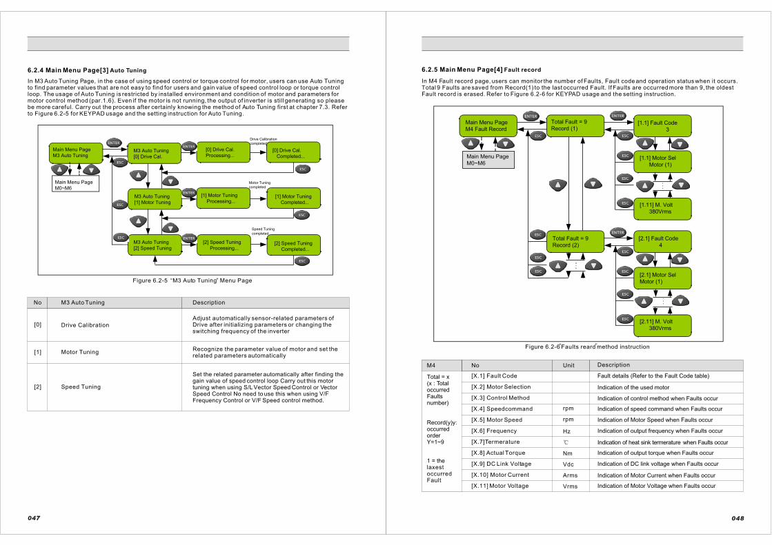
6.2.4 Main Menu Page[3] Auto Tuning
In M3 Auto Tuning Page, in the case of using speed control or torque control for motor, users can use Auto Tuningto find parameter values that are not easy to find for users and gain value of speed control loop or torque controlloop. The usage of Auto Tuning is restricted by installed environment and condition of motor and parameters for motor control method (par.1.6). Even if the motor is not running, the output of inverter is still generating so pleasebe more careful. Carry out the process after certainly knowing the method of Auto Tuning first at chapter 7.3. Referto Figure 6.2-5 for KEYPAD usage and the setting instruction for Auto Tuning.
Main Menu Page
M3 Auto TuningM3 Auto Tuning
[0] Drive Cal.
[0] Drive Cal.
Processing...[0] Drive Cal.
Completed...
Main Menu Page
M0~M6
M3 Auto Tuning
[1] Motor Tuning
[1] Motor Tuning
Processing...[1] Motor Tuning
Completed...
M3 Auto Tuning
[2] Speed Tuning
[2] Speed Tuning
Processing...[2] Speed Tuning
Completed...
Speed Tuning
completed
Motor Tuning
completed
Drive Calibration
completed
Figure 6.2-5 M3 Auto Tuning Menu Page“ ”
No
[0]
[1]
[2]
M3 Auto Tuning
Motor Tuning
Speed Tuning
Drive Calibration
Description
Adjust automatically sensor-related parameters of Drive after initializing parameters or changing the switching frequency of the inverter
Recognize the parameter value of motor and set the related parameters automatically
Set the related parameter automatically after finding thegain value of speed control loop Carry out this motor tuning when using S/L Vector Speed Control or VectorSpeed Control No need to use this when using V/FFrequency Control or V/F Speed control method.
047
6.2.5 Main Menu Page[4] Fault record
In M4 Fault record page, users can monitor the number of Faults, Fault code and operation status when it occurs.Total 9 Faults are saved from Record(1) to the last occurred Fault. If Faults are occurred more than 9, the oldest Fault record is erased. Refer to Figure 6.2-6 for KEYPAD usage and the setting instruction.
Main Menu Page
M4 Fault Record
Total Fault = 9
Record (1)[1.1] Fault Code
3
[1.1] Motor Sel
Motor (1)
[1.11] M. Volt
380Vrms
[2.1] Fault Code
4
Total Fault = 9
Record (2)
[2.1] Motor Sel
Motor (1)
[2.11] M. Volt
380Vrms
Main Menu Page
M0~M6
Total = x(x : TotaloccurredFaultsnumber)
Record(y)y:occurredorderY=1~9
1 = the laxestoccurredFault
M4 No Unit Description
[X.1] Fault Code
[X.2] Motor Selection
[X.3] Control Method
[X.4] Speedcommand
[X.5] Motor Speed
[X.6] Frequency
[X.7]Termerature
[X.8] Actual Torque
[X.9] DC Link Voltage
[X.10] Motor Current
[X.11] Motor Voltage
rpm
rpm
Hz
Nm
Vdc
Arms
Vrms
Fault details (Refer to the Fault Code table)
Indication of the used motor
Indication of control method when Faults occur
Indication of speed command when Faults occur
Indication of Motor Speed when Faults occur
Indication of output frequency when Faults occur
Indication of heat sink termerature when Faults occur
Indication of output torque when Faults occur
Indication of DC link voltage when Faults occur
Indication of Motor Current when Faults occur
Indication of Motor Voltage when Faults occur
048
Figure 6.2-6 Faults reard method instruction“ ”

6.2.6 Main Menu Page[5] Initialize
In M5 Initialize page, users can remove of the recorded Fault list, reset the system ofinverter Drive and return to the default parameter values.Refer to Figure 6.2-7 for KEYPAD usage and the setting instruction.
Main Menu Page
M5 Initialize
M5 Initialize
[0] Clr FaultList[0] Clr FaultList
Completed...
M5 Initialize
[1] System Reset
[1] System Reset
Reset -> <ENTER>
M5 Initialize
[2] Parameter
[1] Parameter
Initializing...
[0] Motor Speed
0 rpm
M3 Auto Tuning
[0] Drive Cal.ERR [Warning]
W14 Drive Cal.
After Parameter Initialize ,
Drive Calibration Error occurs.
Return to the M3 display by Menu Key
Execute the Calibration of Auto Tuning
After Initialization ,
It moves to the initial display.
blink
Main Menu Page
M0~M6
No M5 Initialize Description
Clear Fault List remove the recorded fault details
reset the system of the inverter (Same effect to give themain power back again after turn off the inverter.)
return all the parameters to the default value If DriveCalibration Warning (W14) occurs, this carries out theDriveCalibration function of Auto Tuning[0] of Main Menu Page[3]
System Reset
Parameter Restore[2]
[1]
[0]
049
Figure 6.2-7 M5 Initialize Menu Page“ ”
6.2.7 Main Menu Page[6] Password
In M6 password Page, users can check what access level of parameters can be edited. If a user wants to change the inverter parameters for more professional level, the user must be certified for higher level access. Certifying the higher level access can be done at "Admission" with the relevant password for each level. Then, theparameters of the higher level can be accessed. It is recommended to use Access level from 0 to 1 for normal users(L[0] ~ L[1]). If users want higher level, please contact the head office. If users are certified higher than L[1], it will be returned to L[0] automatically after 1 hour passes.Refer to Figure 6.2-8 for KEYPAD usage and the setting instruction.
1
1
Main Menu Page
M6 Password
Main Menu Page
M0~M6
M6 Password
[0] Access = [L0]
M6 Password
[1] Admission[1] Admission
Password [L1]
Password [L1]
Enter : 0000
If the password
of L1 is 0100
Password [L1]
Enter : 0100
Blink
Password [L1]
Admitted. [L1]
[1] Admission
Password [L2]
L2-L5 have the
same procedure of
setting as L1
*) Input the old password.
The procedure is the same
as in [1] Admission of M6
Password
*) after input the
old passwordPassword [L1]
Enter : 0000
New Password [L1]
Enter : 0000*) Input the new password.
The procedure is the same as
[1] Admission of M6 Password
L2-L5 have the
same procedure
of setting as L1
[1] Admission
Password [L2]
New Password [L1]
Completed...
M6 Password
[2] Pwd Change[2] Pwd Change
Password [L1]
Figure 6.2-8 M6 Password Menu Page“ ”
No M6 Password Description
[0] Access Level Indication of certified Access level
[1] AdmissionL[1] : Password 0 0 0 0
[2] Password ChangeChange the password for the certified level (userscan directly change the password)
050
L[2]:L[5] Consult with our compang
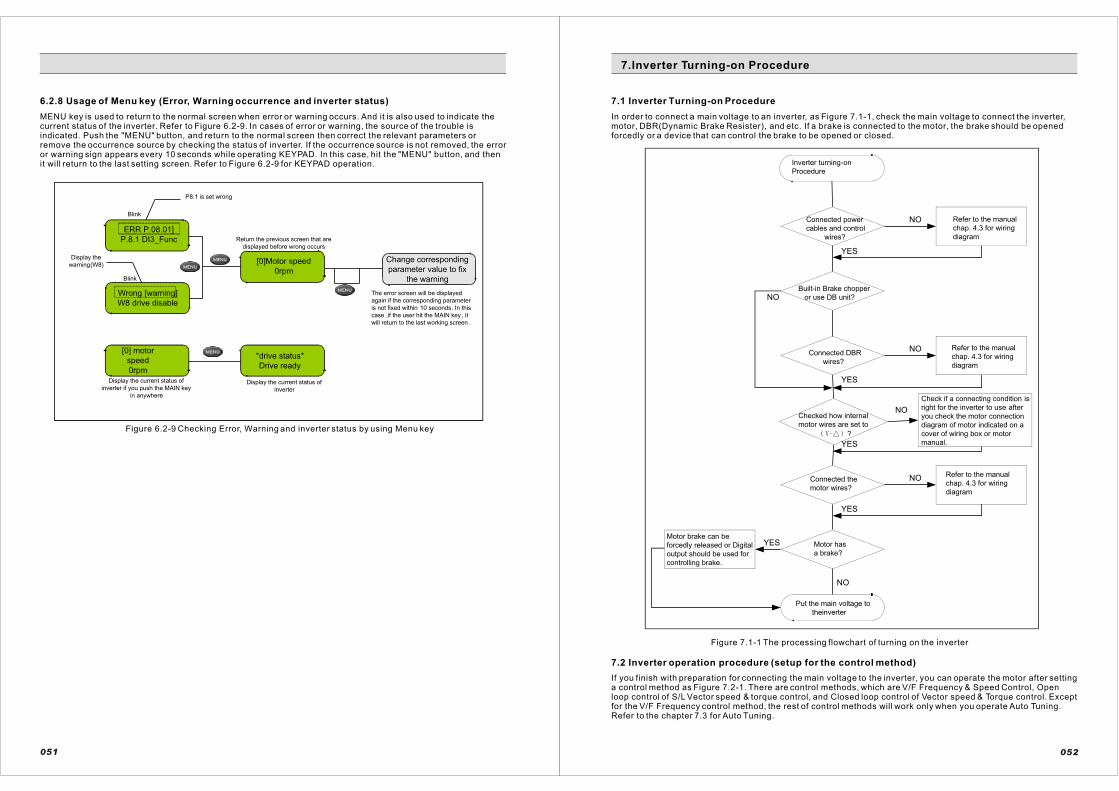
6.2.8 Usage of Menu key (Error, Warning occurrence and inverter status)
MENU key is used to return to the normal screen when error or warning occurs. And it is also used to indicate thecurrent status of the inverter. Refer to Figure 6.2-9. In cases of error or warning, the source of the trouble isindicated. Push the "MENU" button, and return to the normal screen then correct the relevant parameters or remove the occurrence source by checking the status of inverter. If the occurrence source is not removed, the erroror warning sign appears every 10 seconds while operating KEYPAD. In this case, hit the "MENU" button, and thenit will return to the last setting screen. Refer to Figure 6.2-9 for KEYPAD operation.
P8.1 is set wrong
Return the previous screen that are
displayed before wrong occurs
The error screen will be displayed
again if the corresponding parameter
is not fixed within 10 seconds. In this
case ,if the user hit the MAIN key , it
will return to the last working screen .
Display the current status of
inverter if you push the MAIN key
in anywhere
Display the current status of
inverter
ERR P.08.01]
P.8.1 DI3_Func
Wrong [warning]
W8 drive disable
[0]Motor speed
0rpm
Change corresponding
parameter value to fix
the warning
[0] motor
speed
0rpm
*drive status*
Drive ready
Display the
warning(W8)
Blink
Blink
Figure 6.2-9 Checking Error, Warning and inverter status by using Menu key
051
7.1 Inverter Turning-on Procedure
In order to connect a main voltage to an inverter, as Figure 7.1-1, check the main voltage to connect the inverter,motor, DBR(Dynamic Brake Resister), and etc. If a brake is connected to the motor, the brake should be opened forcedly or a device that can control the brake to be opened or closed.
NO
NO
NO
NO
NO
YES
YES
NO
YES
YES
YES
Put the main voltage to
theinverter
Motor has
a brake?
Motor brake can be
forcedly released or Digital
output should be used for
controlling brake.
Connected the
motor wires?
Refer to the manual
chap. 4.3 for wiring
diagram
Check if a connecting condition is
right for the inverter to use after
you check the motor connection
diagram of motor indicated on a
cover of wiring box or motor
manual.
Refer to the manual
chap. 4.3 for wiring
diagram
Refer to the manual
chap. 4.3 for wiring
diagram
Built-in Brake chopper
or use DB unit?
Connected power
cables and control
wires?
Inverter turning-on
Procedure
Connected DBR
wires?
Checked how internal
motor wires are set to
?
Figure 7.1-1 The processing flowchart of turning on the inverter
If you finish with preparation for connecting the main voltage to the inverter, you can operate the motor after setting a control method as Figure 7.2-1. There are control methods, which are V/F Frequency & Speed Control, Openloop control of S/L Vector speed & torque control, and Closed loop control of Vector speed & Torque control. Except for the V/F Frequency control method, the rest of control methods will work only when you operate Auto Tuning.Refer to the chapter 7.3 for Auto Tuning.
7.2 Inverter operation procedure (setup for the control method)
052
7.Inverter Turning-on Procedure

7.2.1 Open Loop Control Procedure
Figure 7.2-1 The processing flowchart of Open Loop Control operation
053
7.2.2 Close Loop Control Procedure
Figure 7.2-1 The processing flowchart of open Loop Control operation054
NO
YES
YES
YES
NO
NO
NO
NO
NO
NO
YES
YES
NO
Operation ProcedureOpen Loop Control Setting
Followed the turn-on Procedure
in Chapter 7.1?
Refer to the turn-on
Procedure in Ch. 7.1
Turn on the inverter
Charging Error occurs? Check the input voltage
and the wiring condition.
Brake Damage
Error occurs?Check DBR, Brake
Chopper (DB Unit)
Go to
Main Menu Page (2)
M2 Parameter Edit
Parameter Group 0 / P.0.1~P.0.3 =Standard I
Parameter Group 1 / Motor 1 Control setting, P.1.0~P.1.9Refer to the chap. 6.2.7 Password
Refer to the Motor Name Plate
P.1.6 Control Method
= ?
P1.6=0 : V/F Frequency
P1.6= 1 : V/F Speed
2 : S/L Speed
Set up Parameter
Group
3,5,6,7,8,9,11,12,13?
Use as a Default value
If Error occur
Hit the MENU key
Go to Main Menu Page (3)
M3 Auto Tuning
Excute [1] Motor Tuning
Auto Tuning
Complete
Auto Tuning
Interuppted
Set up the each
parameters depending
on operating character
and I/O composition
P.15.0
Torque Compensator
= ?
Operate Speed Loop
Tuning?P15.0=1 : Auto
P15.0=0 : Manual
Set the V/F Pattern control
parameters, P15.7~P15.12
If Error occur
Hit the MENU key
P1.6 = 2
S/L Speed
P.17.14
Speed PI Gain
= 0 : Default
Go to Main Menu Page ( )
M2 Auto Tuning
Execute [2] Speed Tuning
Auto Tuning
Complete
Auto Tuning
Interuppted
Retry the
Auto Tuning
Set up
Parameter Group
3,5,6,7,8,9,11,12,13?
YES(Refer to chap. 7.4)
Use as a Default value
Set up the each
parameters depending
on operating character
and I/O composition
[Setting Completed]
Operate the inverter with Keypad
or I/O Terminals
" "
" "
NO
YES
YES
YES
NO
NO
NO
NO
NO
YES
YES
NO
YES
NO
Operation Procedure
Close loop control setting
Followed the turn-on
procedure in chap. 7.1
Refer to inverter turn -on
procedure in chap. 7.1
Main voltage to inverter
Charging error occurs?Check the main voltage
and wiring condition.
Brake damage
error occurs?
Check DBR ,brake
chopper(DB UNIT)
Parameter group 0/P.0.1~P.1.3=shandard II setting
Move to the MAIN Menu Page (5) M5 initialize
Operate [1] system reset
Parameter Group 1
Motor 1 control setting
P.1.0~P.1.5,1.9
Refer to the keypad
password in chap.6.2.7
Refer to the in chap.6.2.6
Refer to the motor name plate
Is set the encoder?Set up encoder or use V/F
frequency or V/F speed control
Encoder setting
use V/F frequency or
V/F speed control
P1.6=[0]V/F FrequencyP.1.6 Control method=?
P1.6=[1]V/F Speed
or [3] Vector Speed
Error occurs.
Push the MENU key
Use as a
default value
Set up the parameter group
3,5,6,7,8,9,11,12,13
Set up the each
parameter of inverter
depending on
operating character
and I/O compositiom.
YES (refer to
operation procedure
in the chap.7.4)
Move to the Main menu page (3)
M3 auto tuning.
Operate the motor tuning .
Auto tuning complete Auto tuning interruppted
Retry auto
tuning
P.15.0
Torque compensator=?
P.15.0=[1] Auto
P.15.0=[0] Manual
Set up the V/F
pattern control
parameters
P15.7~P15.17
Error occurs push
the MENU key
Move to the Menu page(3)
M3 auto tuning.
Operate [2] speed tuning
Operate speed loop
turning?
P1.6=[3]
Vector speedP19.19 speed PI
gain =[0] default
Retry auto
tuning
auto tuning
interruptted
auto tuning
complete
Set up the
parameter group
3,5,6,7,8,9,11,12,
13?YES (refer to the
operation procedure in
chap.7.4)Use as a
default value Set up the each parameter of
inverter depending on operating
character and I/O composition
[setting completed]
Operate the inverter by keypad or I /O terminals
" "
" "
Figure 7.2-2 The processing flowchart of Close Loop Control operation

7.3 Auto-Tuning Procedure
7.3.1 Checking point before Auto Tuning
ChecklistStep
Check 1
Is a motor Shaft connected to the other machine?
In a process of Auto Tuning the motor can rotate up to about 5% of the rated speed.In this case, if the motor is connected to a processing line or other machine, check out whether or not there is any effect from the motor rotation. If there is a possibilityof causing a fatal problem, you need to operate Auto Tuning after you separate the motor from other device. If it is difficult to separate you need to make a condition for operation that will not cause any problem even if the motor rotates. The bestcondition of Auto Tuning is when there is no load of the motor and mechanicaldevices are connected as they are. Especially in Speed Tuning, you can get moreexact result when the entire mechanical devices are connected.
Does the motor have any load or is it connected to a Mechanical Brake?
If the Brake is installed to the motor, it should possibly be released during the Auto-Tuning process. You can release the Brake by your hands or connect the Brake Control Circuit to the Digital Output terminal of the inverter. If the Brake can bereleased, check if P.14.0=0(free). After it is released, if the load that is more than 50% of the rated load is impressed, Auto tuning may not be smooth. If you are in a situation that you have to operate Auto Tuning while the Brake is closed, you needto set up P.14.0=1(Locked). And only Motor Tuning is possible to operate, but not aSpeed Tuning. If the Speed Tuning does not operate, set P17.14, P18.14, P19.19,P20.19 to 0(Default) and then use. In this case, you use the factory-setting valuesfor a speed controller.
Is there a big difference between the motor power and the inverter power?
Auto Tuning may not operate well if power of the motor to connect to the inverter istoo small in comparison with that of the inverter. The motor power should be at leastover 1/5 of the inverter power.
Did you input the motor specification in Parameter Group1?
Set up the rated power, voltage, current, speed, and number of poles of the motorto the parameter items that are conformed to the Parameter Group 1. Refer to the rating plate information on the motor.
Is an encoder connected to the motor?
In case of using Vector Control, an encoder should be installed to the motor. But without installing it, V/F Control or S/L Vector Control can operate Auto Tuning.
Check 2
Check 3
Check 4
Check 5
055
7.3.2 Auto Tuning Operation & Completion
Auto tuning process
NO
NO
NO
NO
NO
NO
YES
YES
YES
YES
YES
YES
Checked the operating
condition like check 1 and 2 of
chap.7.3.1?
Check a device
connected to a motor
and the load condition
Is a brake installed
to a motor?
Refer to check 3 of
chap.7.3.1 check brake
control of a motor
Is the power of motor
more than 1/5 of inverter
power?
Refer to check 3 of
chap.7.3.1 check brake
control of a motor
Followed chap.7.1 inverter
turn on procedure?
Refer to chap.7.1
inverter turn on
procedure
Put the main voltage
to the inverter
Go to main menu page(2)
M2 parameter edit
Parameter group 1 motor 1 control setting
P1.0: motor rated power setting [kW]
P1.1: motor rated voltage setting [V]
P1.2: motor rated current setting [A]
P1.3: motor rated frequency setting [Hz]
P1.4: motor pole setting [pole]
P1.5: motor rated speed setting [rpm]
Is an encoder
installed?
M3 auto tuning
[2] speed tuning
M3 auto tuning
processing...
P1.6=1V/Fspeed
P1.6 control method
=[2]S/Lvector_ctrl
or[3]vector _ctrl
Error [tuning]
F(code)M3auto tuning
complete
M3 auto tuning
processing...
M3 auto tuning
[1] motor tuning
ERR. [P.21.0]
P.21.0 Pri. Res.
-refer to the pre-checking items
before auto tuning in chap . 7.3.1
-refer to chap. 8 protection
M3 auto tuning
interrupt...
P1.6 control method
=[1]V/F speed
Or [2]S/L vector
P1.6 control method
=[3]vector_ctrl
Attention!
If a bbrake cannot be
released set P14.0 to
[0] free. The speed
tuning cannot be
operated.
Refer to the
motor plate
If error occur
push the menu
key
Go to the
speed tuning
item
Refer to the chap. 6.2.7
keypad passwordRefer to the chap. 6.2.6
Move to the main menu page (5)
M5 initialize
Operate [1] system reset
Parameter group0/
P.0.1~P1.3 =
standardIIsetting
Retry motor
tuning
Retry motor
tuning
Go to main
menu page (3)
M3auto tuning
-check the brake operating condition
-refer to the pre-checking items
before auto tuning in chap . 7.3.1
-refer to chap. 8 protection
M3auto tuning
complete
M3 auto tuning
interrupt...
Retry auto
tuning
Error [tuning]
F(code)
auto tuning completed
Figure 7.3-1 The processing flowchart of Auto Tuning
056

7.4.1 Basic Design
057 058
R
S
T
MCCB
440Vac
M1 Fuse1
Reactor
(optional)
RFI
Filter
(optional)
TC1
RC1
220VacL1 L2 L3
*)Vin reference+multi step use
Refer to the chap.7.4.3 item 1
+
-
Voltage
reference
0~10V
5k 2w
NO
1
2
3
4
5
6
7
8
9
10
11
12
13
14
15
16
17
18
19
20
21
22
23
24
25
26
terminal description
Voltage reference group
10Vdc supply terminal
Analog input 1 terminal
0~10V use as volt. ref.
Analog input 2 terminal
0(4)~20mAuse as cur. Ref.
Forword run
Reverse run
Drive enable
External fault input
Digital input group
Fault reset
Mult-step 0
Mult-step 1
Mult-step 2
Digital input group
Analog output 0(4)~20mA
Digital output 3-open collector
Digital output +24V
Brake control
Fault output
Current
reference
0(4)~20mAM2FWD
REV
R1
R3
R6
MS0
MS1
MS2
A
Meter
Range
0~100A-
+Analog output 0(4)~20mA
DO
1
DO
2
DO
3
DO1.A
DO1.B
DO1.C
DO2.A
DO2.B
DO2.C
HP vector
control
inverter
Vref.COM
Vref.+10V
AI 1.P
AI 1.N
AI 2.P
AI 2.N
DI.01
DI.04
DI.03
DI.02
DI.COM
DI.COM
DI.05
DI.06
DI.07
DI.08
AO1.N/DI.COM
AO.P
DO3.OC
DO3.24V
Hoist brake have to be operated with
using by the brake control relay of
inverter .
(in case of PLC control , using brake
control relay makes safety increase .)
NOTE
Brake
control
unit
Brake
device
Use this when brake
control is needed
U V W
M
22kW,440V,38.9A
50Hz 1770rpm 4pole
R-R+
THR
DBR
Brake chopper
(optional)
speed
1
2
3
4
5
6
7
ON
Operation&mult-step
sequence diagram
TC1
RC1
TC1
RC1
R1
R1 R2 R3 R4 R5 R6M2 GM1
fuse 1
fuse 2
fuse 3
R1
R2
R3
R4
THR R1DO
2DO
1
DO
3 R5Main
sequence
diagram
FWD REV 1N 2N 3N 4N 5N 7N6N MS0 MS1 MS2
1N 2N 3N 4N 5N 7N6NFWD REV
1N
2N3N
4N5N
7N 6N
2N
4N 6N
4N
Major
controlfuse Thermal
relay
Main
power Brake
Use this when brake
control is needed
Ramp
ready
Fuse2
Fuse3
DI.06 DI.07 DI.08
ON
ON ON
ON
ON ON
ON ON
ON ON ON
OFF OFF
OFFOFF
OFF
OFF OFF
OFF
OFF
Fault
reset
inverter
FaultFault
resetinverter
ready
speed
1
2
3
4
5
6
7
ON
DI.06 DI.07 DI.08
ON
ON ON
ON
ON ON
ON ON
ON ON ON
OFF OFF
OFFOFF
OFF
OFF OFF
OFF
OFF
7.4 Basic Open Loop Control Operation Procedure
The chapter 7.4 explains the most basic application method for operating the inverter with Open Loop Control.
The following design allows you to use all the basic I/O functions when you use HPVFV inverter. You can adjust it depending on the given condition on the field.
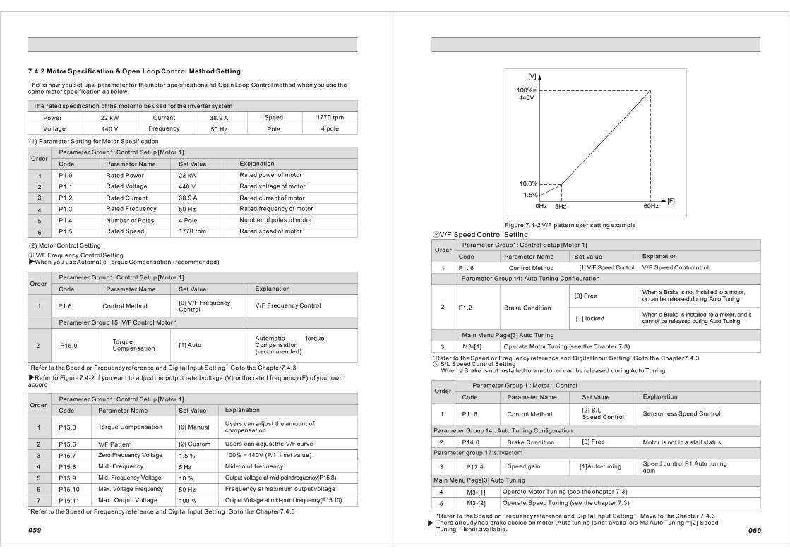
7.4.2 Motor Specification & Open Loop Control Method Setting
This is how you set up a parameter for the motor specification and Open Loop Control method when you use the same motor specification as below.
The rated specification of the motor to be used for the inverter system
Power
Voltage
22 kW Current
440 V Frequency
38.9 A
50 Hz Pole
Speed 1770 rpm
4 pole
(1) Parameter Setting for Motor Specification
OrderParameter Group1: Control Setup [Motor 1]
Code Parameter Name Set Value Explanation
P1.0
P1.1
P1.2
P1.3
P1.4
P1.5
Rated Power
Rated Voltage
Rated Current
Rated Frequency
Number of Poles
Rated Speed 1770 rpm
4 Pole
50 Hz
38.9 A
440 V
22 kW Rated power of motor
Rated voltage of motor
Rated current of motor
Rated frequency of motor
Number of poles of motor
Rated speed of motor
(2) Motor Control Setting
Parameter Group1: Control Setup [Motor 1]
Code Parameter Name Set Value Explanation
V/F Frequency Control Setting When you use Automatic Torque Compensation (recommended)
P1.6
Order
Control Method[0] V/F Frequency Control
V/F Frequency Control
Parameter Group 15: V/F Control Motor 1
P15.0TorqueCompensation
[1] AutoAutomatic TorqueCompensation(recommended)
Refer to Figure 7.4-2 if you want to adjust the output rated voltage (V) or the rated frequency (F) of your own accord
Parameter Group1: Control Setup [Motor 1]
Code Parameter Name Set Value Explanation
P15.0
Order
Torque Compensation [0] ManualUsers can adjust the amount ofcompensation
P15.7
5 Hz
P15.6 [2] CustomV/F Pattern Users can adjust the V/F curve
Zero Frequency Voltage 1.5 % 100% = 440V (P.1.1 set value)
P15.8 Mid. Frequency Mid-point frequency
P15.9 Mid. Frequency Voltage 10 % Output voltage at mid-pointfrequency(P15.8)
P15.10
P15.11
Max. Voltage Frequency 50 Hz Frequency at maximum output voltage
Max. Output Voltage 100 % Output Voltage at mid-point frequency(P15.10)
Refer to the Speed or Frequency reference and Digital Input Setting Go to the Chapter 7.4.3
1
2
3
4
5
6
1
2
1
2
3
4
5
6
7
059
Refer to the Speed or Frequency reference and Digital Input Setting Go to the Chapter7.4.3“ ”
“ ”
[V]
[F]
10.0%
5Hz
1.5%
0Hz
100%=
440V
60Hz
Figure 7.4-2 V/F pattern user setting example
Parameter Group1: Control Setup [Motor 1]
Code Parameter Name Set Value Explanation
P1. 6
Parameter Group 14: Auto Tuning Configuration
P1.2
Control Method
Brake Condition
[0] Free
[1] V/F Speed Control V/F Speed Controlntrol
When a Brake is not installed to a motor, or can be released during Auto Tuning
When a Brake is installed to a motor, and it cannot be released during Auto Tuning[1] locked
Main Menu Page[3] Auto Tuning
3 M3-[1] Operate Motor Tuning (see the Chapter 7.3)
Refer to the Speed or Frequency reference and Digital Input Setting Go to the Chapter7.4.3 S/L Speed Control Setting
When a Brake is not installed to a motor or can be released during Auto Tuning
Parameter Group 1 : Motor 1 Control
P1. 6 Control Method[2] S/LSpeed Control
Sensor less Speed Control
Order
P14.0 Brake Condition [0] Free Motor is not in a stall status
M3-[1] Operate Motor Tuning (see the chapter 7.3)
M3-[2] Operate Speed Tuning (see the chapter 7.3)
Refer to the Speed or Frequency reference and Digital Input Setting Move to the Chapter 7.4.3 There alreudy has brake decice on moter ,Auto tuning is not availa lole M3 Auto Tuning = [2] Speed Tuning isnot available.
1
2
060
“ ”
V/F Speed Control Setting
Code Parameter Name Set Value Explanation
Parameter Group 14 : Auto Tuning Configuration
Main Menu Page[3] Auto Tuning
1
4
5
Order
3
2
P17.4 Speed gain [1]Auto-tuning Speed control P1 Auto tuninggain
Parameter group 17:s/l vector1
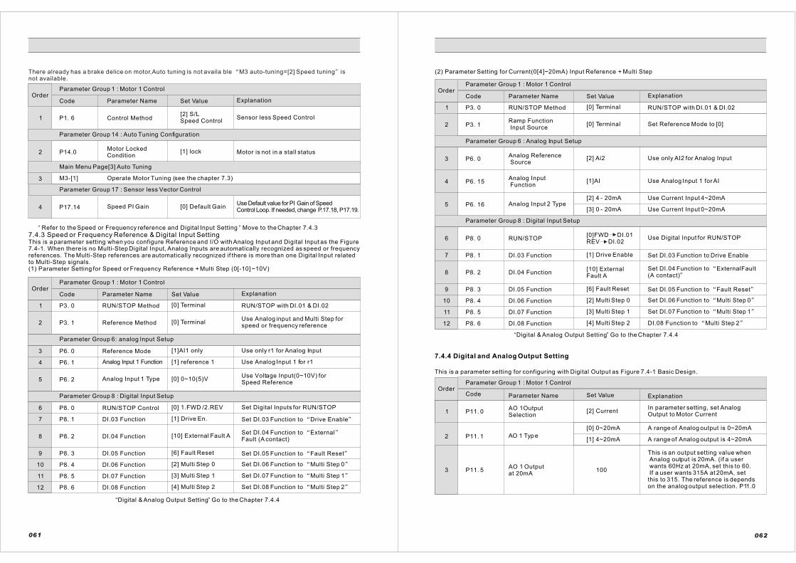
Parameter Group 1 : Motor 1 Control
Motor is not in a stall status
Code Parameter Name Set Value Explanation
P1. 6 Control Method[2] S/LSpeed Control
Sensor less Speed Control
P14.0Motor LockedCondition
[1] lock
M3-[1] Operate Motor Tuning (see the chapter 7.3)
P17.14 Speed PI Gain [0] Default GainUse Default value for PI Gain of Speed Control Loop. If needed, change P.17.18, P17.19.
“ ”Refer to the Speed or Frequency reference and Digital Input Setting Move to the Chapter 7.4.3
7.4.3 Speed or Frequency Reference & Digital Input SettingThis is a parameter setting when you configure Reference and I/O with Analog Input and Digital Input as the Figure7.4-1. When there is no Multi-Step Digital Input, Analog Inputs are automatically recognized as speed or frequencyreferences. The Multi-Step references are automatically recognized if there is more than one Digital Input related to Multi-Step signals.(1) Parameter Setting for Speed or Frequency Reference + Multi Step (0[-10] ~10V)
Parameter Group 1 : Motor 1 Control
Code Parameter Name Set Value Explanation
P3. 0 RUN/STOP Method [0] Terminal RUN/STOP with DI.01 & DI.02
P3. 1 Reference Method [0] TerminalUse Analog input and Multi Step for speed or frequency reference
P6. 0 Reference Mode [1]AI1 only Use only r1 for Analog Input
P6. 1 Analog Input 1 Function [1] reference 1 Use Analog Input 1 for r1
P6. 2 Analog Input 1 Type [0] 0~10(5)VUse Voltage Input(0~10V) for Speed Reference
P8. 0 RUN/STOP Control [0] 1.FWD /2.REV Set Digital Inputs for RUN/STOP
P8. 1 DI.03 Function [1] Drive En. Set DI.03 Function to Drive Enable
P8. 2 DI.04 Function [10] External Fault ASet DI.04 Function to ExternalFault (A contact)
P8. 3 DI.05 Function [6] Fault Reset Set DI.05 Function to Fault Reset
P8. 4 DI.06 Function [2] Multi Step 0 Set DI.06 Function to Multi Step 0
P8. 5 DI.07 Function [3] Multi Step 1 Set DI.07 Function to Multi Step 1
P8. 6 DI.08 Function [4] Multi Step 2 Set DI.08 Function to Multi Step 2
“ ”Digital & Analog Output Setting Go to the Chapter 7.4.4
061
(2) Parameter Setting for Current(0[4]~20mA) Input Reference + Multi Step
Parameter Group 1 : Motor 1 Control
Code Parameter Name Set Value Explanation
P3. 0 RUN/STOP Method [0] Terminal RUN/STOP with DI.01 & DI.02
[0] TerminalP3. 1Ramp Function Input Source
Set Reference Mode to [0]
P6. 0Analog Reference Source
[2] Ai2 Use only AI2 for Analog Input
P6. 15Analog Input Function
[1]AI Use Analog Input 1 for AI
P6. 16 Analog Input 2 Type[2] 4 - 20mA
[3] 0 - 20mA
Use Current Input 4~20mA
Use Current Input 0~20mA
P8. 0 RUN/STOP[0]FWD DI.01REV DI.02
Use Digital Input for RUN/STOP
P8. 1 DI.03 Function [1] Drive Enable Set DI.03 Function to Drive Enable
Set DI.04 Function to ExternalFault(A contact)
P8. 2 DI.04 Function[10] ExternalFault A
P8. 3 DI.05 Function [6] Fault Reset Set DI.05 Function to Fault Reset
P8. 4 DI.06 Function [2] Multi Step 0 Set DI.06 Function to Multi Step 0
P8. 5 DI.07 Function [3] Multi Step 1 Set DI.07 Function to Multi Step 1
P8. 6 DI.08 Function [4] Multi Step 2 DI.08 Function to Multi Step 2
This is a parameter setting for configuring with Digital Output as Figure 7.4-1 Basic Design.
Parameter Group 1 : Motor 1 Control
Code Parameter Name Set Value Explanation
P11. 0AO 1OutputSelection
[2] CurrentIn parameter setting, set AnalogOutput to Motor Current
P11. 1 AO 1 Typ e
[0] 0~20mA
[1] 4~20mA
A range of Analog output is 0~20mA
A range of Analog output is 4~20mA
This is an output setting value when Analog output is 20mA. (if a user wants 60Hz at 20mA, set this to 60. If a user wants 315A at 20mA, setthis to 315. The reference is depends on the analog output selection. P11.0
P11. 5AO 1 Output at 20mA
100
“ ”Digital & Analog Output Setting Go to the Chapter 7.4.4
7.4.4 Digital and Analog Output Setting
062
Parameter Group 14 : Auto Tuning Configuration
Main Menu Page[3] Auto Tuning
Parameter Group 17 : Sensor less Vector Control
Order
1
2
3
4
Order
Parameter Group 6: analog Input Setup
Parameter Group 8 : Digital Input Setup
1
2
3
4
5
6
7
8
9
10
11
12
Order
Parameter Group 6 : Analog Input Setup
Parameter Group 8 : Digital Input Setup
Order
1
2
3
4
5
6
7
8
9
10
11
12
1
2
3
There already has a brake delice on motor,Auto tuning is not availa ble M3 auto-tuning=[2] Speed tuning isnot available.

Parameter Group 3 : Reference Setup
Code Parameter Name Set Value Explanation
Order Parameter Group 12 : Digital Output Setup
P12. 0 DO 1 Function [4] Motor_Brake
Set Dig i ta l Output Funct ion toMagnetic Brake of Motor. (When youuse Motor Brake Control, refer to theChapter 7.4.6 Brake Control Setting)(referto#21#22#23terminals)
P12. 1 DO 2 Function [2] Fault OutAWhen Fault occurs set Digital OutputFunction to work (A OPt)(refer to #24 #25 #26 terminals)
P12. 2 DO 3 Function [1] Drive Ready Operate when the inverter is ready
“ ”Refer to the Operation Pattern Setting Go to the Chapter 7.4.5
It explains parameter settings when you set the Operation Pattern as Figure 7.4-3 and 7.4-4. TheFigure 7.4-1 shows the basic input method.(1) When you use V/F Frequency and V/F Speed Control
Analog order value 0~10V or 0(4)~20mA
Contact point input MS 0,MS 1, MS 2=OFF
Contact point input MS 0,MS 1,MS 2
=more than one ON
10s
DC braking time
=P15.15=0.5s
Start DC brake
blangking time
P15.16=0.2s
(100%=P1.2)
Start DC brake
current =P15.17=75%
P15.2=60Hz
Accel. Time =P3.16
P15.1=2Hz
speed1N
speed2N
speed3N
speed4N
speed5N
speed6N
speed7N
P9.1=5%(3Hz)
P9.2=10%(6Hz)
P9.3=30%(18Hz)
P9.4=50%(30Hz)
P9.5=70%(42Hz)
P9.6=80%(48Hz)
P9.7=100%(60Hz)
Free-run
stop
Ramp
stop
RUN ON
StopDI.01
DI.02OFF
12sDecel. Time =P3.33
Stop
blanking time
P15.19=0.3s 1s
Stop DC
braking time
=P15.18=4s
t
3s
(100%=P1.2)
Stop DC braking hold time
=P15.17=75%
(100%)=P1.2
Stop DC brake
P15.21=110%
Figure 7.4-3 Operation Pattern Setting of V/F Frequency and V/F Speed Control
Reference Setup Setting
P3.3 STOP Mode
[0] Ramp Stop
[1] Free-Run Stop
When Run-Input signal is turned OFF, inverter stops after Decel Time
When Run-Input Signal is turned OFF,Inverter output is also turned OFF immediately.
P3.9Accel.SwitchingRef[1-2]
100%100% = Rated Speed or RatedFrequency of Motor
P3.16 Accel.Time Region 1 10sAccel.Time Region 1 See the explanation of parameter
7.4.5 Operation Pattern Setting
063
Code Parameter Name Set Value Explanation
Parameter Group 3 : Reference Setup
Code Parameter Name Set Value Explanation
P3.26Decel.Switching Ref[1-2]
100%100% = Rated Speed or RatedFrequency of Motor
P3.33Decel.TimeRegion 1 12s
Decel.Time Region 1See the explanation of parameter
Multi Step Reference Setting
Parameter Group 9: Multi Step Reference(100% = Rated Speed or Rated Frequency of Motor)
P9.1 Multi Step 1 Reference 5% 60Hz X 5% = 3Hz
P9.2 Multi Step 2Reference 10% 60Hz X 10% = 6Hz
P9.3 Multi Step 3 Reference 30% 60Hz X 30% = 18Hz
P9.4 Multi Step 4 Reference 50% 60Hz X 50% = 30Hz
P9.5 Multi Step 5 Reference 70% 60Hz X 70% = 42Hz
P9.6 Multi Step 6 Reference 80% 60Hz X 80% = 48Hz
P9.7 Multi Step 7 Reference 100% 60Hz X 100% = 60Hz
Parameter Setting for V/F Frequency or V/F Speed Control
Parameter Group 15 : V/F Control [Motor 1]
Code Parameter Name Set Value Explanation
P15.1Minimum outputFrequency 2 Hz Set up for Minimum Output Frequency
P15.2Maximum outputFrequency 60 Hz Set up for Maximum Output Frequency
P15.15 Start DC Brake [Time] 0.5s Operating time of DC Brake while running
P15.16Start DC Brake [Blank Time] 0.2s
When starting, Accel time for DC Brake current
P15.17Start DC Brake[Current]
75% When starting, DC Brake current
P15.18Stop DC Brake [Time]
4sOperating time of DC Brake whilestopping
P15.19Stop DC Brake [Blank Time]
0.3sWhen stopping, Accel time for DCBrake current
P15.20 Stop DC Brake [Current] 75% When stopping, DC Brake current
P15.21Stop DC Brake [Frequency] 110%
Operating frequency of DCBrake while stopping (100=P1.2)
<Inverter Setting completed!> *When you use the Brake Control of Motor go to The Chapter7.4.6. Brake Control Setting using Digital Output
“
”
064
4
5
6
Order
1
2
3
Order
Order
Order
1
2
1
2
3
1
2
3
4
5
6
7
4
5
6
7
8
9
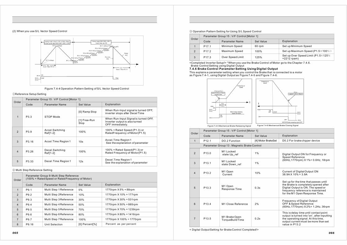
Code Parameter Name Set Value Explanation
Parameter Group 9: Multi Step Reference(100% = Rated Speed or Rated Frequency of Motor)
(2) When you use S/L Vector Speed Control
Parameter Group 15 : V/F Control [Motor 1]
Code Parameter Name Set Value Explanation
Analog oeder value 0~10V or 0(4)~20mA
Contact point input MS 0,MS 1,MS 2=OFF
Contact input MS 0,MS 1,MS 2
=more than one ON
10s
P17.2=1770rpm
Accel. Time=P3.16
P17.2=60rpm
speed1N
speed2N
speed3N
speed4N
speed5N
speed6N
speed7N
P9.1=5%(88rpm)
P9.2=10%(177rpm)
P9.3=30%(531rpm)
P9.4=50%(885rpm)
P9.5=70%(1239rpm)
P9.6=80%(1416rpm)
P9.7=100%(1770rpm)
DI.01
DI.02
Decel. Time=P3.33
t12s
Free-run
stop
Ramp
stop
Stop
RUN ON
OFF
Figure 7.4-4 Operation Pattern Setting of S/L Vector Speed Control
Reference Setup Setting
P3.3 STOP Mode
[0] Ramp Stop
[1] Free-RunStop
When Run-Input signal is turned OFF,inverter stops after Decel Time
When Run-Input Signal is turned OFF,Inverter output is also turned OFF immediately.
P3.9Accel.SwitchingRef[1-2]
100%100% = Rated Speed (P1.3) orRatedFrequency of Motor(P1.5)
P3.16 Accel.Time Region 1 10sAccel.Time Region 1 See the explanation of parameter
P3.26Decel.SwitchingRef[1-2]
100%100% = Rated Speed(P1.3) orRated Frequency of Motor(P1.5)
P3.33 Decel.Time Region 1 12sDecel.Time Region 1See the explanation of parameter
P9.1 Multi Step 1 Reference 5% 1770rpm X 5% = 88rpm
P9.2 Multi Step 2Reference 10% 1770rpm X 10% = 177rpm
P9.3 Multi Step 3 Reference 30% 1770rpm X 30% = 531rpm
P9.4 Multi Step 4 Reference 50% 1770rpm X 50% = 885rpm
P9.5 Multi Step 5 Reference 70% 1770rpm X 70% = 1239rpm
P9.6 Multi Step 6 Reference 80% 1770rpm X 80% = 1416rpm
P9.7 Multi Step 7 Reference 100% 1770rpm X 100% = 1770rpm
P9.16 Unit Selection [0] Percent[%]
Multi Step Reference Setting
065
Operation Pattern Setting for Using S/L Speed Control
Parameter Group 15 : V/F Control [Motor 1]
Code Parameter Name Set Value Explanation
P17.1 Minimum Speed 60 rpm Set up Minimum Speed
P17.2 Maximum Speed 100% Set up Maximum Speed (P1.5 100
P17.3 Over Speed Limit 125%Set up Over Speed Limit (P1.5 125=2212 rpam)
<Completed Inverter Setup!> *When you use the Brake Control of Motor go to the Chapter 7.4.6. Brake Control Setting using Digital Output
7.4.6 Brake Control Parameter Setting Using Digital Output
This explains a parameter setting when you control the Brake that is connected to a motoras Figure 7.4-1, using Digital Output as Figure 7.4-5 and Figure 7.4-6.
P13.0 or P13.1
speed>0.6Hz or 18rpm
current>3.9A
Frequency or
speed
t
Motor brake releasing
signal ON=open
0.3s
P13.3RUN
ON
DI.01
DI.02
DO.2
ON
OFF
t
RUN
ON
ONOFF
OFF
STOP DI.01
DI.02
DO.2
MOTOR Brake resealing signal OFF
speed<1.2Hz or 36rpm
P13.4
Frequency or
speed
Figure 7.4-6 Mechanical Brake Closing SignalFigure 7.4-5 Mechanical Brake Releasing Signal
Parameter Group 15 : V/F Control [Motor 1]
Code Parameter Name Set Value Explanation
P12.1 DO.2 Function [4] Motor BrakeSet D0.2 For brake chpper device
P13.0M1 Locked state Up_ref 1%
P13.1M1 Lockedstate Down_ref 1%
Digital Output ON for Frequency orSpeed Reference(60Hz,1770rpm) X 1%= 0.6Hz, 18rpm
P13.2M1 Open Current
10%Current of Digital Output ON38.9A X 10% = 3.9A
P13.3M1 OpenResponse Time
0.3s
Set up for the time that passes untilthe Brake is completely opened afterDigital Output is ON. The speed orfrequency reference is maintainedfor the M1 Open Response Time.
P13.4 M1 Close Reference 2%
Frequency of Digital OutputOFF & Speed Reference(60Hz,1770rpm) X 2%= 1.2Hz, 36rpm
P13.5M1 Brake Open TorqueBuild Time
0.2s
< Digital Output Setting for Brake Control Completed!>
066
This is delay time until contact point output is turned into 'on', after inputting the operating signal. At this time, output current must be more than set value in P13.2
Order
Order
1
2
3
4
5
1
2
3
4
5
6
7
8
Order
1
2
3
Order
Parameter Group 13 : Magnetic Brake Control
4
5
6
1
2
3
7
Percent as per percent

8.1 Parameter table
Parameter Group 0: Program Control
Par.NOParameter NameLCD Display Unit Default Range Access
LevelNote
P 0.1Program Boot_Key1Prog_Key 1 0
[0] Standard I[1] Standard II[2] Application
1
P 0.2Program Boot_Key2Prog_ Key 2 0
[0] Standard I[1] Standard II[2] Application
1
P 0.3Program Boot_Key3Prog_Key 3 0
[0] Standard I[1] Standard II[2] Application
1
P 0.12
Initialization_Permission_KeyParIni_Key
[Hex] 0 0 ~ 39321 1
P 0.13Drive Voltage ClassVolt_Class 0
[0] 200 / 400 / 500[1] 600V 1
1
1[0]Thermal_Rly[1] NTC_Thermistor1
1
Thermal_MonitorClassThermalMon
P 0.15
P 0.14
Parameter Group 1: Control Setup [Motor 1]
Changing the default value by the model and capacity of inverter.
Par.NOParameter NameLCD Display Unit Default Range Access
LevelNote
P 1.0Rated PowerM1_Rtd_Pwr kW 0 0 ~ 1000 0
P 1.1Rated VoltageM1_Rtd_Volt Vrms 0 ~ 1500
Refer tomotor'sname plate
0 0
P 1.2Rated CurrentM1_Rtd_Curr
Arms 0 00 ~ 2000
Norminal_FrequencyClassFreq_Class
[0] 50 Hz [1] 60 Hz
067
8. Parameter
P 1.3Rated FrequencyM1_Rtd_Freq Hz 0 0 ~ 3000
Refer to motor's nameplate
0
P 1.4Number of PolesM1_Pole
Pole 0 00 ~ 24
P 1.5Rated SpeedM1_Rtd_Spd
rpm 1800 0 ~ 60000 2
P 1.6Control MethodM1_Control
[0] V/F Freq
[1] V/F Speed
[2] S/L_Vector
[3] Vector_Ctrl
00
P 1.7PWM FrequencyM1_PWM_Freq kHz 2.5 0.8 ~ 10 1
Supply voltageSupply_VoltP 1.9 Vrms 0 ~ 1500 00
Parameter Group 2: Control Setup [Motor 2]
Parameter NameLCD DisplayPar.NO Unit Default Range Access
LevelNote
P 2.0Rated PowerM2_Rtd_Pwr kW 0 0 ~ 1000 2
P 2.1Rated VoltageM2_Rtd_Volt Vrms 0 0 ~ 1500 2
P 2.2Rated CurrentM2_Rtd_Curr
Arms 0 0 ~ 2000 2
P 2.3Rated FrequencyM2_Rtd_Freq Hz 0 0~3000 2
P 2.4Number of PolesM2_Pole
Pole 0 0~24 2
P 2.5Rated SpeedM2_Rtd_Spd
rpm 0 0~60000 2
Refer to motor's nameplate
Refer to motor's nameplate
Refer to motor's nameplate
Refer to motor's nameplate
Refer to motor's nameplate
068

P 2.6Control Method
M2_Control0 2
PWM Frequency
M2_PWM_FreqP 2.7 kHz 2.5 0.8 ~ 10 2
P 2.9Supply voltageSupply_Volt Vrms 0 0~1500 2
P 3.0 0
P 3.1 0
Par.NOParameter NameLCD Display Unit Default Range Access
LevelNote
RUN/STOP MethodRUN/STOP
0
[0] Terminal[1] Operator[2] Sync Ctrl Bus[3] Fieldbus
(Profibus,Modbus, CANbus)
RampFunc_Input_SrcRamp_Input
[0] Terminal (Digital, Analog)[1] Operator(RS 232C)[2]Syncctrlbus[3] Free Func
0
P 3.2 0 ~ 10 0
P 3.3STOP ModeSTOP Mode
0
[0] Ramp STOP[1] Free-Run STOP[2] Mixed STOP
0
P 3.4STOP Hold TimeStopHold_Tm
S 0.00 0 ~ 300 0
P 3.5Output Off Hold TimeOut_off _Tm
S 1.00 0.1 ~ 30 0
P 3.6
Mixed_mode StopReferenceOUT_off_Ref
20.0 0 ~ 500 0
P 3.7Acc/Dec Ramp FunctionAcc/Dec_En 1
[0] Disabled[1] Enabled 0
%
Refer to motor's name plate
Parameter Group 3: Reference Setup [Motor1]
s
Stop command Deteltion
Time
Stop Detcet
069
2
P 3.8Acceleration Time RangeAccTm_Range 0
[ 0 ] 1 s e c[ 1] 10sec
0
P 3.9Acc Switching Ref 1-2AccSw 1-2
% 100.00 ~ 300
0
P 3.10Acc Switching Ref 2-3AccSw 2-3
% 150.0 0 ~ 300 0
P 3.11Acc Switching Ref 3-4AccSw 3-4
% 200.0 0 ~ 300 0
P 3.12Acc Switching Ref 4-5AccSw 4-5
225.0 0 ~ 300
P 3.13Acc Switching Ref 5-6AccSw 5-6 % 250 0 ~ 300 0
P 3.14Acc Switching Ref 6-7AccSw 6-7 %
275 0 ~ 300 0
P 3.15Acc Switching Ref 7-8AccSw 7-8 %
300.0 0 ~ 300 0
P 3.16Acc Time I.1Acc_Tm I.1 S 10.00 0.01 ~ 300 0
P 3.17Acc Time I.2Acc_Tm I.2 S
5.00 0.01 ~ 300 0
P3.18 Acc _Time I.3 S 5.00 0.01 ~ 3000
P3.19Acc Time I.4Acc_Tm I.4 S 5.00
0.01 ~ 300
P3.20Acc Time I.5Acc_Tm I.5
S 5.00 0.01 ~ 300
P3.21Acc Time I.6Acc_Tm I.6 S 5.00
0.01 ~ 300
0.01 ~ 3005.00SP 3.22
Acc Time I.7AccTm I .7
P 3.23Acc Time I.8Acc_Tm I.8
S
5.00 0.01 ~ 300
P 3.24Acc Time IIAcc_Tm II
S
10.00 0 ~ 300 0
P 3.25Decel Time RangeDecTm_Rnge 0 0
P 3.26Dec Switching Ref 1-2DecSw 1-2
% 100.0 0 ~ 300 0
P 3.27Dec Switching Ref 2-3DecSw 2-3
% 150.0 0 ~ 300 0
070
[4] Free_Func
[0] V/F Freq
[1] V/F Speed
[2] S/L_Vector
[3] Vector_Ctrl
S
DI=[14]ACC/DEC
[0]0~300S[1]0~3000S
[ 0 ] 1 s e c[ 1] 10sec

P 3.28Dec Switching Ref 3-4DecSw 3-4
% 200.0 0 ~ 300 0
P 3.29Dec Switching Ref 4-5DecSw 4-5
% 225.0 0 ~ 300 0
P 3.30Dec Switching Ref 5-6DecSw 5-6
% 250.0 0 ~ 300 0
P 3.31Dec Switching Ref 6-7DecSw 6-7
% 275.0 0 ~ 300 0
P 3.32Dec Switching Ref 7-8DecSw 7-8
% 300.0 0 ~ 300 0
P 3.33Decel Time I.1Dec_Tm I.1
s 5.00 0 ~ 300 0
P 3.34Decel Time I.2Dec_Tm I.2
s 5.00 0 ~ 300 0
P 3.35Decel Time I.3D e c _ T m I . 3
s 5.00 0.01 ~ 300 0
P 3.36Decel Time I.4D e c _ T m I . 4
s 5.00 0.01 ~ 300 0
P 3.37Decel Time I.5D e c _ T m I . 5
s 5.00 0.01 ~ 300
P 3.38Decel Time I.6D e c _ T m I . 6
s 5.00 0.01 ~ 300
0
0
P 3.39Decel Time I.7D e c _ T m I . 7
s 5.00 0.01 ~ 300 0
P 3.40Decel Time I.8D e c _ T m I . 8 5.00 0.01 ~ 300 0
P 3.41Decel Time IIDec_Tm II
s
s 10.00 0 ~ 300 0
P 3.42
Counter DecelerationRamp FunctionC_Decel_En
00[0] Disabled[1] Enabled
P 3.43
Counter DecelerationTimeC_Decel_Tm
5.00s 0 ~ 300 0
P 3.49Emergemcy_Stop MODEES_Mode
0
[0] Ramp STOP[1] Free-Run[2] Mixed STOP
0
P 3.50
Emergemcy_STOPDecel_TimeES_DecTime
s 1.00 0.001 ~ 30 0
071
P 3.52Reverse_DIR_ OperationRev_Dir_EN 1
[0]Disabled[1]Enabled 0
Par.NOParameter NameLCD Display Unit Default Range Access
LevelNote
P4.0RUN/STOP MethodRUN/STOP
0
[0] Terminal[1] Operator (RS 232C)[2] Synchronous_Ctrl[3]Fieldbus(Profibus,Modbus, CANbus)[4] Free Function Logic
P4.1RampFunc_Input_SrcRamp_Input 0
[0] Terminal(Digital, Analog)[1] Operator (RS 232C)[2] SyncctrlBus[3] Free -Func
2
2
P4.3
Stop Command DetectionTimeSTOP Detect
s 0 0 ~ 10 2
STOP ModeSTOP Mode
0
[0] Ramp STOP[1] Free-Run STOP[2] Mixed STOP
2
P4.4STOP Hold-TimeStopHold_Tm
s 0 0 ~ 300 2
P4.5Output OFF Hold-TimeOut_off_Tm
s 1.00 0.1~300 2
P4.6
Mixed-Mode STOPReferenceOut_off_Ref
% 20.0 0 ~ 500 2
P4.7Acc/Dec Ramp EnableAcc/Dec_En 1
[0]Disabled[1]Enabled
2
P4.8Accel_Time RangeAccTm_Range 0
[0]1sec[1]10sec
2
P4.9Acc Switching Ref 1-2AccSw 1-2
% 100.0 0 ~ 300 2
P4.10Acc Switching Ref 2-3AccSw 2-3
% 150.0 0 ~ 300
0 ~ 300
0 ~ 300
2
2
2
200.0
225.0
%
%
P4.11
P4.12
Acc Switching Ref 3-4AccSw 3-4
Acc Switching Ref 4-5AccSw 4-5
Parameter Group4:Referenence setup (motor2)
P4.2
072
P 3.51Continuous OP ModeCONTINU_OP
1.00[0]Disabled[1]Enabled 0
DI=[14]Acc/Dec
P4.3=[2]Mixed stop
P4.3=[1]Free-run stop
P4.3=[0]rampstop

P4.14Acc Switching Ref 6-7 AccSw 6-7
% 275.0 0 ~ 300 2
20 ~ 300 300.0%Acc Switching Ref 7-8AccSw 7-8
P4.15
P4.16Acc Time I.1 Acc_TmI.1
S 5.00 0.01 ~ 300 2
P4.17Acc Time I.2Acc_TmI.2
S 5.00 0.01 ~ 300 2
P4.18Acc Time I.3 Acc_Tm I.3
S 5.00 0.01 ~ 300 2
P4.19Acc Time I.4 Acc_Tm I.4
S 5.00 0.01 ~ 300 2
S 5.00 0.01 ~ 300 2P4.20Acc Time I.5 Acc_Tm I.5
P4.21Acc Time I.6 Acc_Tm I.6
S 5.00 0.01 ~ 300 2
P4.22Acc Time I.7 Acc_Tm I.7
S 5.00 0.01 ~ 300 2
P4.23Acc Time I.8 Acc_Tm I.8
S 5.00 0.01 ~ 300 2
P4.24Acc Time II Acc_Tm II S 10.00 0.01 ~ 300 2
P4.25Decel Time RangeDecTm_Rnge 0
[0] 1sec[1] 10sec 2
P4.26Dec Switching Ref 1-2 DecSw 1-2
% 100.0 0 ~ 300 2
P4.27Dec Switching Ref 2-3DecSw 2-3
% 150.0 0 ~ 300 2
P4.28Dec Switching Ref 3-4 DecSw 3-4
% 0 ~ 300 2
225.0P4.29Dec Switching Ref 4-5 DecSw 4-5
% 0 ~ 300 2
250.0P4.30Dec Switching Ref 5-6DecSw 5-6
200.0
% 0 ~ 300 2
P4.31Dec Switching Ref 6-7DecSw 6-7
% 0 ~ 300 2275.0
P4.32Dec Switching Ref 7-8DecSw 7-8
% 0 ~ 300 2300.0
073
P 4.33Decel Time I.1 DecTmI.1
s 5.00 0.01 ~ 300 2
P 4.34Decel Time I.2 DecTm I.2
s 5.00 0.01 ~ 300 2
P 4.35Decel Time I.3 DecTm I.3
s 5.00 0.01 ~ 300 2
P4.36Decel Time I.4 DecTm I.4
s 5.00 0.01 ~ 300 2
P4.37Decel Time I.5 DecTm I.5
s 5.00 0.01 ~ 300 2
P4.38Decel Time I.6D e c T m I . 6
s 5.00 0.01 ~ 300 2
P4.39Decel Time I.7 DecTm I.7
s 5.00 0.01 ~ 300 2
P4.40Decel Time I.8DecTm I.8
s 5.00 0.01 ~ 300 2
P4.41Decel Time II Dec_Tm II
s 10.00 0.01 ~ 300 2
P4.42
Counter DecelerationRamp FunctionC_Decel_En
0[0] Disabled[1] Enabled 2
P4.43
Counter DecelerationTimeC_Decel_Tm
5.00s 2
P4.49
Emergency_STOPModeES_Mode
0
[0] Ramp STOP[1] Free-RUN[2] Mixed STOP
2
P4.50
Emergency_STOP Decel_TimeES_DecTime
s 1.00 0.01~10 2
P4.51Continuous OP_ModeCONTINU_OP
1.00[0] Disabled[1] Enabled 2
P4.52Reverse_DIR_ OperationRev_Dir_EN
1.00[0] Disabled[1] Enabled 2
Parameter Group 5: Protection
Par.NOParameter NameLCD Display Unit Range Access
LevelDefault Note
P5.0Current Limit [Motor1] I_Limit[M1]
% 145.0 1
0.01 ~ 300
074
P4.13Acc Switching Ref 5-6AccSw 5-6
% 250.0 0 ~ 300 2

P5.1Current Limit [Motor2] I_Limit[M2]
% 130.0 2
P5.7Max. Continuous CurrentMaxCon_Curr
% 95.0 0 ~ 250 1
P5.8Over-Load currentOver_Load
% 135.0 0 ~ 250 1
P5.9Over-Load TimeOL_TimeOver
s 60.00 0 ~ 300 1
P5.10Over-Load Fault [Action] OL_Action
0
[0] STOP[1] E_STOP[2] Ctrl-OFF [3] IGNORE
0
P5.11
Over-Current Trip[motor1]OC_Trip_M1
% 220.0 0 ~ 350 2
P5.12
Zero-sequence CurrentTripZC_Trip
% 15.0 0 ~ 100 2
P5.13
Over-Voltage Limiting FunctionOV_Ltd_Fn
0[0] Disabled[1] Enabled 1
P5.14Over Voltage LimitOV Limit
V 350.0 0 ~ 850 1
P5.15Over Voltage tripOV Trip V 360.0 0 ~ 900 2
P5.16
UV compensation_VoltageUV_Comp_Fn
1[0] Disabled[1] Enabled 1
P5.17 V
UV compensation_VoltageUV_Comp_V
450 0 ~ 1000 1
P5.18Under Voltage TripUV_Trip V 360 0 ~ 1000 2
P5.19Open Phase Protection OP_Ph_Trip 1
[0]Disabled[1]Enabled 0
P5.20Supply FrequencyInput_Freq Hz 60.0 0 ~ 100 0
P5.21Built-in Dynamic BrakeBlt-in_DB 1
[0] Disabled[1] Enabled_RUN[2] En_RUN_STOP
0
075
P5.23DB StartDB_Start_V V 690 300 ~ 850 1
P5.24DB Full VoltageDB_Full_V V 710.0 300 ~ 850
P5.25
Over-Temperature Trip
[Action]
OT_Action
2
[0] STOP[1] E_STOP[2] CTRL_OFF [3] IGNORE[4] SPEED_DOWN
1
P5.30Auto Restart Count RestartCnt
0 0 ~ 10 1
P5.31Retry Delay TimeRetry_Dly S 1.5 0 ~ 100 1
P5.32Auto Reset (OC) A.Rst_OC
0 0 ~ 100 1
P5.33Auto Reset (OV)A.Rst_OV
0[0]Disabled[1]Enabled 1
P5.34Auto Reset (UV)A.Rst_UV 0
[0] Disabled[1]Enabled 1
Out of Control Auto-ResetA.Rst_CnEr
P5.37 0[0]Disabled[1]Enabled 1
P5.38Out of Control TimeCntlErr_Tm S 5.0 0.1 ~ 1000 1
P5.39Out of Control CurrentCtrl_Err_I
% 90.0 50 ~ 97.5 1
P5.40Over TemperatureOver_Temp
Deg 75.0 60~125
P5.41Over-Current Trip[II]OC_Trip_M2
% 200 0 ~ 800 3
Parameter Group 6: Analog Input
Par. NOParameter Name LCDDisplay Unit Default Range Access
LevelNote
P6.0
Analog ReferenceSourceAI_Ref_Src
1
[0] Disabled[1] AI 1Ref [2] AI 2Ref
0
P6.1AI.1 FunctionAI1 Func
1[0] Disabled[1] Analog-In 0
P6.2AI.1_TypeAI1 Type 0
[0] 0 ~ 10(5)V [1] -10 ~ 10V[2] 4 ~ 20mA[3] 0 ~ 20mA
0
5
076
Restart delay time

P6.4AI.1 Filter Time ConstAi1 Tm_Ct
ms 25.0 1 ~ 2000 0
P6.5AI.1 OffsetAI1 Offset
mA/ V 0.000 -10 ~ 10 0
P6.6AI.1 min VoltageAI1 Min_V
V 0.000 0 ~ 9 0
P6.7AI.1 min Current AI1 Min_mA mA 0.00 0 ~ 18 0
0P6.8AI.1 MinimumAI1 Min.
% 0.0 0 ~ 500
P6.9AI.1 Max VoltageAI1 Max_V V 10.00 1 ~ 10 0
P6.10AI.1 max Current AI1 Mx_mA mA 20.00 2 ~ 20 0
P6.11AI.1 MaximumAI1 Max.
% 100.0 0 ~ 500 0
P6.12AI.1 InversionAI1 Inv
0[0]Disabled[1]Enabled 0
P6.13AI.1 Discreteness AI1 D_Step 0
[0]Disabled[1]128Steps[2]64Steps[3]32Steps[4]16Steps[5]8Steps
0
P6.14AI. 1 Dead-Zone AI1 Dead-Z
0[0] Disabled[1] Enabled 0
P6.15AI.2 FunctionAI2 Func
1[0] Disabled[1] Analog-In 0
P6.16AI.2 TypeAI2 Type 3
[0] 0 ~ 10(5)V [1] -10 ~ 10V[2] 4 ~ 20mA[3] 0 ~ 20mA
0
P6.19
AI.2 Filter Time ConstAI2 Tm_Ct
Ms 25.0 1 ~ 2000 0
AI.2 OffsetAI2 Offset
mA/ V 0.000 -10 ~ 10 0
P6.18
P6.20AI.2 Min VoltageAI2 Min_V V 0.000 0 ~ 9 0
0P6.21AI.2 Min Current AI2 Min_mA mA 0.000 0 ~ 18
077
P6.22AI.2 MinimumAI2 Min.
% 0.0 0 ~ 500 0
P6.23AI.2 Max VoltageAI2 Max_V V 10.00 1 ~ 10 0
P6.24AI.2 Max Current AI2 Mx_mA mA 20.00 2 ~ 20 0
P6.25AI.2 MaximumAI2 Max.
% 100.0 0 ~ 500 0
P6.26AI.2 InversionAI2 Inv.
0[0]Disabled[1]Enabled 0
P6.27AI.2 Discreteness AI2 D_Step 0
[0] Disabled[1] 128 Steps [2] 64 Steps [3] 32 Steps [4] 16 Steps [5] 8 Steps
0
P6.28AI. 2 Dead-Zone AI2 Dead-Z
0[0]Disabled[1]Enabled 0
P6.29AI.3 FunctionAI3 Func
0[0] Disabled[1] Analog-In 2
P6.30AI.3 TypeAI3 Type 0
[0] 0 ~ 105V[1] -10 ~ 10V[2] 4 ~ 20mA[3] 0 ~ 20mA
2
P6.32AI.3 Filter Time ConstAi3 Tm_Ct
ms 25.0 1 ~ 2000
P6.33AI.3 OffsetAi3 Offset
mA/ V 0.000 -10 ~ 10
2
2
P6.34AI.3 Min VoltageAi3 Min_V V 0.000 0 ~ 9 2
P6.35AI.3 Min Current Ai3 Min_mA mA 0.000 0 ~ 18 2
P6.36AI.3 MinimumAI3 Min.
% 0.0 0 ~ 500 2
P6.37AI.3 Max VoltageAI3 Max_V V 10.00 1 ~ 10 2
P6.38AI.3 Max Current AI3 Mx_mA mA 20.00 2 ~ 20 2
P6.39AI.3 MaximumAI3 Max.
% 100.0 0 ~ 500 2
P6.40AI.3 InversionAI3 Inv.
0[0] Disabled[1] Enabled 2
078
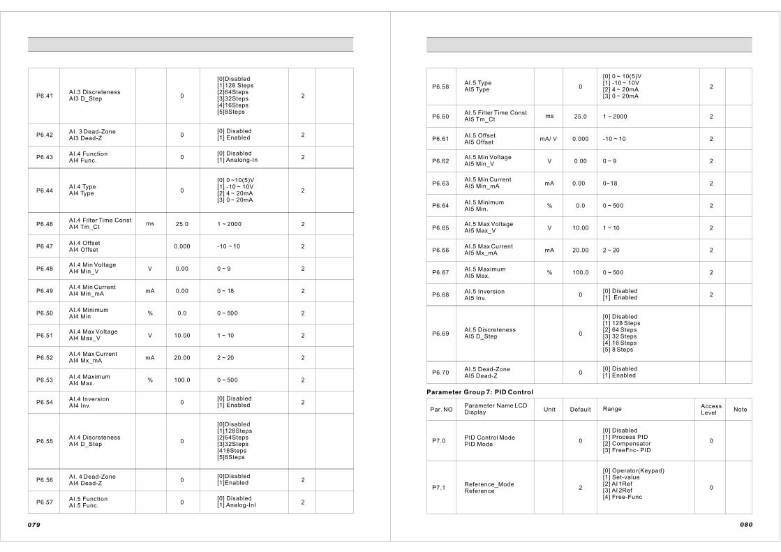
P6.41AI.3 Discreteness AI3 D_Step 0
[0]Disabled[1]128 Steps[2]64Steps[3]32Steps[4]16Steps[5]8Steps
2
P6.42AI. 3 Dead-Zone AI3 Dead-Z
0[0] Disabled[1] Enabled 2
P6.43AI.4 FunctionAI4 Func.
0[0] Disabled[1] Analong-In 2
P6.44AI.4 TypeAI4 Type 0
[0] 0 ~10(5)V [1] -10 ~ 10V[2] 4 ~ 20mA[3] 0 ~ 20mA
2
P6.46AI.4 Filter Time ConstAI4 Tm_Ct
ms 25.0 1 ~ 2000 2
P6.47AI.4 OffsetAI4 Offset
mA
0.000 -10 ~ 10 2
P6.48AI.4 Min VoltageAI4 Min_V V 0.00 0 ~ 9 2
P6.49AI.4 Min Current AI4 Min_mA 0.00 0 ~ 18 2
P6.50AI.4 MinimumAI4 Min
% 0.0 0 ~ 500 2
P6.51AI.4 Max VoltageAI4 Max_V V 10.00 1 ~ 10 2
P6.52AI.4 Max Current AI4 Mx_mA mA 20.00 2 ~ 20 2
P6.53AI.4 MaximumAI4 Max.
% 100.0 0 ~ 500 2
P6.54AI.4 InversionAI4 Inv.
0[0] Disabled[1] Enabled 2
P6.55AI.4 Discreteness AI4 D_Step 0
[0]Disabled[1]128Steps[2]64Steps[3]32Steps[416Steps[5]8Steps
2P6.56AI. 4 Dead-Zone AI4 Dead-Z
0[0]Disabled[1]Enabled
P6.57 0[0] Disabled[1] Analog-InI 2
AI.5 FunctionAI.5 Func.
079
P6.58AI.5 TypeAI5 Type 0
[0] 0 ~ 10(5)V [1] -10 ~ 10V[2] 4 ~ 20mA[3] 0 ~ 20mA
P6.60AI.5 Filter Time ConstAI5 Tm_Ct
ms 25.0 1 ~ 2000
2
2
P6.61AI.5 OffsetAI5 Offset
mA/ V 0.000 -10 ~ 10 2
P6.62AI.5 Min VoltageAI5 Min_V V 0.00 0 ~ 9 2
2
2
2
P6.63AI.5 Min Current AI5 Min_mA mA 0.00 0~18
P6.64AI.5 MinimumAI5 Min.
% 0.0 0 ~ 500
P6.65AI.5 Max VoltageAI5 Max_V V 10.00 1 ~ 10
P6.66AI.5 Max Current AI5 Mx_mA mA 20.00 2 ~ 20 2
2
2
P6.67AI.5 MaximumAI5 Max.
% 100.0 0 ~ 500
P6.68AI.5 InversionAI5 Inv.
0[0] Disabled[1] Enabled
P6.69AI.5 Discreteness AI5 D_Step 0
[0] Disabled[1] 128 Steps [2] 64 Steps [3] 32 Steps [4] 16 Steps [5] 8 Steps
P6.70AI.5 Dead-ZoneAI5 Dead-Z
0[0] Disabled[1] Enabled
Parameter Group 7: PID Control
Par. NOParameter Name LCDDisplay Unit Default Range Access
LevelNote
P7.0PID Control Mode PID Mode
0
[0] Disabled[1] Process PID[2] Compensator[3] FreeFnc- PID
0
P7.1Reference_ModeReference
2
[0] Operator(Keypad)[1] Set-value[2] AI 1Ref [3] AI 2Ref [4] Free-Func
0
080

P7.2Fixed Set-PointFixed_SetPt
% 0.0 0 ~ 400 0
P7.3Feedback_SrcFeedback
1
[0] AI 1Fb [1] AI 2Fb [2] Free Func
0
P7.4Reference Sign ChangeREF_Sgn_Neg 00
[0]Disabled[1]Enabled
P7.5Feedback Sign ChangeFB_Sng_Neg 0
[0]Disabled[1]Enabled 0
P7.6Control PeriodCntl Period
ms 10 1 ~ 1000 0
P7.7Proportional GainP-Gain
% 5.0 0 ~ 3000 0
P7.8Integration TimeInteg_Time S 30.00 0 ~ 300 0
P7.9
Differentiator TimeConstantDiff_Time
ms 0 0 ~ 30000 0
P7.10Feedforward GainFF-Gain
% 0.0 0 ~ 200 0
P7.11Zero-Shift Factor 1 ZERO_Adj 1 % 100.0 5 ~ 100 0
P7.12Proportional Gain 2 P-Gain 2
% 5.0 0 ~ 1000 0
P7.13Integration Time 2 Int_Time 2 S 30.00 0 ~ 300 0
P7.14
Differentiator TimeConstant 2Dif_Time 2
ms
0.0
0 ~ 30000 0
P7.15Feed-Forward Gain2 FF-Gain 2
%
5 ~ 100
0
P7.16Zero-Shift Factor 2 ZERO_Adj 2 % 100.0
0
0 ~ 200
0
P7.17Output InversionOutput_INV
0[0] Disabled[1] Enabled 0
P7.18Integrator Lower Limit Int_Lo_Lmt % 0.0 -300 ~ 300 0
P7.19Integrator Upper LimitInt_Up_Lmt % 100.0 -300 ~ 300 0
P7.20Output Lower Limit Out_Lo_Lmt
% 0.0 -300 ~ 300 0
081
P7.21Output Upper Limit Out_Up_Lmt
% 100.0 -300 ~ 300 0
P7.22
Output_Scale FuncSrcOut_Scale
0 [O] Null Data (0) 0
P7.23Integrator_Ini_ValueInt_St_Val
0 [O] Null Data (0) 0
P7.24AUTO RUN/STOPAuto_RN_ST
0[0] Disabled[1] Enabled 0
P7.25Auto Stop Delay Time AutoSt_Dly S 0.0 0 ~ 3000 0
P7.26
Auto Start ErrorConditionAutoSt_Err
% 10.0 0 ~ 50 0
P7.27Set_Pt Func_SrcRef_Fn_Src
0 [O] Null Data (0) 0
0P7.28Feedback Func_SrcFbk_Fn_Src
0 [O] Null Data (0)
Parameter Group 8: Digital Input Setup
Par. NOParameter NameLCD Display Unit Default
AccessLevel
Note
P8.0
P8.1
P8.2
P8.3
P8.4
P8.5
P8.6
P8.7
P8.8
P8.9
Run/Stop ControlRUN/STOP
Range
[0] 1.FWD / 2.REV[1] 1.RUN / 2.DIR 0
DI 3 FunctionDI.3 Func.
0
DI 4 FunctionDI.4 Func.
10
DI 5 FunctionDI.5 Func.
6
DI 6 FunctionDI.6 Func.
2
DI 7 FunctionDI.7 Func.
3
4DI 8 FunctionDI.8 Func.
0DI 9 FunctionDI.9 Func.
DI 10 FunctionDI.10 Func.
DI 11 FunctionDI.11 Func
0
0
[0] None
[1] Drive- En.
[2] Mutistep-0
[3] Mutistep-1
[4] Mutistep-20
[5] Mutistep-3
[6] Fault Reset
[7] JOG
[8] AI_REF_EN
[9] AI_LOL-Remo
[10] Ext- Fault A
[11] Ext- Fault B
[12] Motor -Sel.
[13] Mt-Brk-St
[14] Accel/Decel
[15] Ref_up
[16] Ref_Doun
[17] Acc/Dec_Byp
[18] PID-Bypass
0
2
082

P8.10DI 12 FunctionDI.12 Func
0
[19] AUTO- PID
[20] PID-GAIN
[21] Rst-PID-INT
[22] Trq_Opt_Byp
[23] Trq-Sign
[24] Trq-2ro-Out
[25] Inching-Run
[26] Slave_RUN
[27]Slu-Opt-Byp
[28] Flying_Start
[29] Disable P/B
P8.15Blank Time after M.C. Blank
0.50 0.1 ~ 2 0
P8.16Ref. Up/Down TimeRef. UP/DN
50.00 1 ~ 30 0
P8.17 0[0] Disabled[1] Enable 0
Flying Start Fly_start
P8.18RUN Delay TimeRUN_Delay 0.00 0 ~ 2
0~30P8.19 Inching-Tm 0.00
0
0
Parameter Group 9: Multi-Step Reference [Motor 1]
Par. NOParameter Name LCD Display Unit Default Range Access
LevelNote
P9.0JOG SetJOG_SetPt
% 20.0 0 ~ 300 0
P9.1Step [1] Set M_Step 1
% 15.0 0 ~ 300 0
0
0
0
0
P9.2Step [2] Set M_Step 2
% 30.0 0 ~ 300
0 ~ 300
0 ~ 300
0 ~ 300
P9.3Step [3] Set M_Step 3
% 50.0
P9.4Step [4] SetM_Step 4
% 100.0
P9.5Step [5] Set M_Step 5
% 100.0
P9.6
P9.7
Step [6] Set M_Step 6 00 ~ 300 % 100.0
00 ~ 300 % 100.0Step [7] Set M_Step 7
s
s
s
s
s
083
P9.8Step [8] Set M_Step 8
% 100.0 0 ~ 300 0
P9.9Step [9] Set M_Step 9
% 100.0 0 ~ 300 0
% 100.0 0 ~ 300 0
% 100.0 0 ~ 300 0
% 100.0 0 ~ 300 0
P9.10
P9.11
Step [10] Set M_Step 10
Step [11]SetM_Step 11
P9.12Step [12] Set M_Step 12
P9.13
P9.14
P9.15
Step [13] Set M_Step 13
Step [14] Set M_Step 14
Step [15] Set M_Step 15
% 100.0 0 ~ 300 0
% 100.0 0 ~ 300 0
00[0] Percent [%] [1] Frequency [Hz]
% 100.0 0 ~ 300 0
P9.16Unit SelectingUnit [%/Hz]
Parameter Group 10: Multi-Step Reference [Motor 2]
Par. NOParameter Name LCD Display Unit Default Range Access
LevelNote
P10.0JOG Reference JOG_SetPt
% 20.0 0 ~ 300 3
P10.1Step [1] Set M_Step 1
% 15.0 0 ~ 300 3
P10.2Step [2] Set M_Step 2
% 30.0 0 ~ 300 3
P10.3Step [3] Set M_Step 3
% 50.0
P10.4Step [4] Set M_Step 4
% 100.0
0 ~ 300 3
0 ~ 300 3
P10.5Step [5] Set M_Step 5
% 100.0 0 ~ 300 3
P10.6Step [6] Set M_Step 6
% 100.0 0 ~ 300 3
% 100.0 0 ~ 300 3P10.7Step [7] Set M_Step 7
P10.8Step [8] Set M_Step 8
% 100.0 0 ~ 300 3
084

P10.9Step [9] Set M_Step 9
% 100.0 0 ~ 300 3
P10.10Step [10] Set M_Step 10
P10.11
P10.12
P10.13
Step [11] SetM_Step 11
Step [12] Set M_Step 12
Step [13] Set M_Step 13
P10.14
P10.15
P10.16
Step [14] Set M_Step 14
Step [15] Set M_Step 15
Unit SelectionU n i t [ % / H z ] 0
[0] [%][1] [Hz] 0
% 100.0 0 ~ 300 3
% 100.0 0 ~ 300 3
% 100.0 0 ~ 300 3
% 100.0 0 ~ 300 3
% 100.0 0 ~ 300 3
% 100.0 0 ~ 300 3
Parameter Group 11: Analog Output Configuration
Par. NO Parameter Name LCD Display Unit Default Range Access
LevelNote
P11.0AO.1 output SelectionAO1 output 1
[0] Frequency
[1] Motor Speed
[2] Out Current
[3] Out-Voltage
[4] Torque
[5] Power-Out
[6] DC-L-Voct
[7] Free_Func
[8] Trim 0 mA
[9] Trim 4 mA
[10] Trim 20 mA
0
P11.1AO.1 TypeAO1 Type
[0] 0 ~ 20mA[1] 4 ~ 20mA 00
P11.2AO.1 Adjustment [0mA]AO10 _Adj
p u 0.0530 0 ~ 0.5 0
P11.3AO.1 Adjustment [4mA]AO1 4_Adj
p u 0.2143 0.15 ~ 0.5 0
P11.4AO.1 Adjustment [20mA]AO120_Adj
% 100 0 ~ 300
0
P11.5AO.1 Max_OutputAO1 Scale
0
0.8560p u 0.5 ~ 1
085
P11.6AO.1 InversionAO1 Inv.
[0] Disabled[1] Enabled
0 0
Parameter Group 12: Digital Output Setup
Parameter Group 13: Motor Brake Control
Par. NO Parameter Name LCD Display Unit Default Range Access
LevelNote
P12.0DO 1 FunctionDO.1 Func.
0P12.1
P12.2
P12.3
P12.4
P12.5
P12.6
P12.7
[0] None
[1] Drive -Ready
[2] Fault-Out A
[3] Fault -Out B
[4] MOTOR -BRAKE
[5] RUN/-STATUS
[6] WARNING
[7] DIRECTION
[8] JOG
[9] OV-OC-UV-Fn
[10]Free Func
DO 2 FunctionDO.2 Func.
DO 3 FunctionDO.3 Func.
DO 4 FunctionDO.4 Func
DO 5 FunctionDO.5 Func
DO 6 FunctionDO.6 Func.
DO 7 FunctionDO.7 Func
DO 8 FunctionDO.8 Func
2
5
1
0
0
0
0
0
2
Par. NO Parameter Name LCD Display Unit Default Range Access
LevelNote
P13.0
P13.1
M1 Locked StateUp_Spd_SetB1_OP_RefU
M1 Locked StateDown_Spd_SetB1_OP_RefD
%
%
4.0 -100 ~ 100 0
P13.2M1_Brk Open CurrentB1_OP_I
%
0.0 -10 ~ 100 0
00 ~ 200
P13.3M1 START Delay_ TimeB1_OP_Time
P13.4M1 Brk_Close Spd_SetB1_CL_Spd
%
s
25.0
0.00
1.0
0 ~ 5
0 ~ 100
0
0
P 13.5
M1_Brk_OPEN_Torque_Build_TimeB1_Trq_Tm
s 0.2 0 ~ 1 0
086

P13.6M2 Locked StateUP_Spd_SetB2_OP_RefU
% 4.0 -10 ~ 10 3
P13.7
M2 Locked StateDOWN_Spd_SetB2_OP_RefD
% 0.0 -10 ~ 10 3
P13.8M2 OPEN Current B2_OP_I
% 25.0 0 ~ 200 3
P13.9 M2 START Delay_ Time B2_OP_Time
s 0.00 0 ~5 3
P13.10
M2_BrkCLOSE Spd_SetB2_CL_Spd
s 1.0 0 ~ 100 3
P13.11
M2_Brk_OPENTorque_Build_TimeB2_Trq_Tm
s 0.2 0 ~ 1 3
Parameter Group 14: Auto Tuning Configuration
Par. NO Parameter Name LCD Display Unit Default Range Access
LevelNote
P14.0Motor tuning ConditionTuning_Con 1
[0] Free[1] Locked 0
P14.1
P14.2
P14.3
P14.4
P14.5
P14.6
P14.7
Low Speed ExcitationFluxExcit_Flix
Starting ExcitationCurrentExc_St Curr
High-Freq ExcitationCurrentHFI_Curr
High-Freq ExcitationFrequencyHFI_Freq
Max. Tuning SpeedTune_Spd_H
Min. Tuning Speed Tune_Spd_L
Excitation stip FrequencyExcit_stip % 70.0
rpm
rpm
75
200
10 ~ 200
-3000 ~ 3000
-3000 ~ 3000
1
1
1
%
%
%
% 95
75
75
30 10 ~ 100
0 ~ 100
0 ~ 100
10 ~ 100
0
0
0
0
087
Parameter Group 15: V/F Control [Motor 1]
Par. NO Parameter Name LCD Display Unit Default Range Access
LevelNote
Torque CompensationTorq_Comp 0 0P15.0
P15.1
P15.2
P15.3
P15.4
P15.5
P15.6
Min. output FreqencyMin_Freq Hz 0.0 0 ~ 3000 0
0
0
0
0
0
P15.7
P15.8
P15.9
P15.10
Max output FrequencyMax_Freq
Torque CompensationF l u x C u r r e n tFLux_Out_I
Torque CompensationTime ConstantTrq_Out_Tm
ms
%
Hz 60.0
50
500.0 20 ~ 3000
0 ~ 150
0 ~ 3000
Speed Detection TimeConstantSpd_Det_Tm
ms 100.0 20 ~ 3000
V/F PatternV/F Curve
0
[0] Linear
[1] Square
[2] User
[3] Free-Func
Zero Frequency Voltage Zr_Freq_V % 1.5 0 ~ 50 0
Mid. FrequencyMid_Freq Hz 6.0 1 ~ 3000 0
Mid. Frequency VoltageMid_Freq-V % 11.0 0 ~ 100 0
0
0
0
3
0
0 ~3000
0 ~ 150
[0] Disabled[1] Enabled
0 ~ 100
0 ~ 30
P15.11
P15.12
P15.14
P15.15
Max Voltage Frequency Max_V_Frq 99.0
100.0
0
Max. Output VoltageMax_Volt
Max. Voltage LimiterMax_V_Ltd
Sq_Crv VoltageCompensationSq_crv_v
% 25.0
DC-Brake Time[START]St_Brk_Tm
s 0.0
P15.16
DC-Brake BlankingTime [START]St_Brk_B
s 0.00 0 ~ 3 0
Hz
%
088
[0] Manual[1] Auto
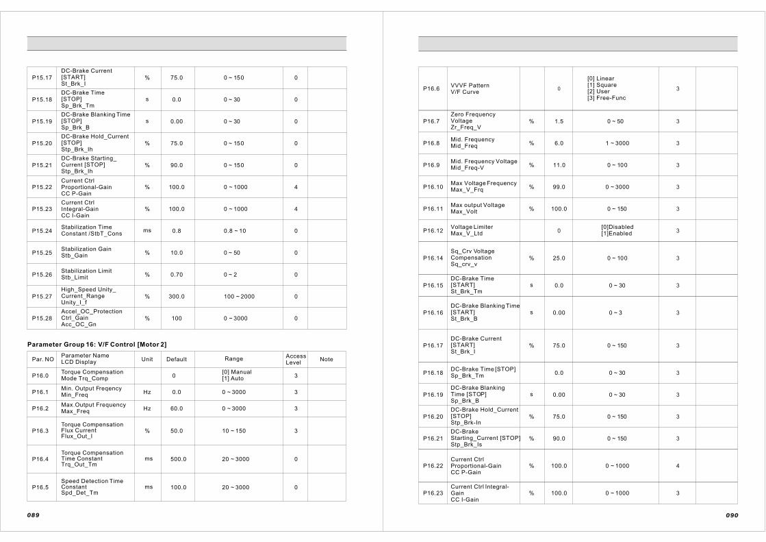
P16.5 0Speed Detection TimeConstantSpd_Det_Tm
ms 100.0 20 ~ 3000
P16.4 0Torque CompensationTime ConstantTrq_Out_Tm
ms 500.0 20 ~ 3000
P15.17
DC-Brake Current[START]St_Brk_I
% 75.0 0 ~ 150 0
P15.18
DC-Brake Time[STOP]Sp_Brk_Tm
s 0.0 0 ~ 30 0
0
0
0
4
P15.19
P15.20
P15.21
DC-Brake Starting_Current [STOP]Stp_Brk_Ih
DC-Brake Hold_Current[STOP]Stp_Brk_Ih
DC-Brake Blanking Time[STOP]Sp_Brk_B
s
%
%
0.00 0 ~ 30
0 ~ 150
0 ~ 1000 P15.22Current CtrlProportional-GainCC P-Gain
%
75.0
90.0
100.0
0 ~ 150
P15.23Current CtrlIntegral-GainCC I-Gain
% 0 ~ 1000 4100.0
P15.24Stabilization TimeConstant /StbT_Cons
ms 0.8 0.8 ~ 10 0
P15.25
P15.26
P15.27
P15.28
Stabilization GainStb_Gain
% 10.0 0 ~ 50 0
Stabilization LimitStb_Limit
% 0.70 0 ~ 2 0
High_Speed Unity_Current_RangeUnity_I_f
% 300.0 100 ~ 2000 0
Accel_OC_ProtectionCtrl_GainAcc_OC_Gn
% 100 0 ~ 3000 0
Parameter Group 16: V/F Control [Motor 2]
Par. NOParameter Name LCD Display Unit Default Range Access
LevelNote
P16.0Torque CompensationMode Trq_Comp 0
[0] Manual[1] Auto 3
P16.1
P16.2
Min. Output FreqencyMin_Freq Hz
Hz
0.0
60.0
0 ~ 3000
0 ~ 3000
3
3
310 ~ 15050.0%Torque CompensationFlux CurrentFlux_Out_I
Max.Output Frequency Max_Freq
P16.3
089
P16.6 0 3VVVF PatternV/F Curve
[0] Linear[1] Square [2] User[3] Free-Func
P16.7
Zero FrequencyVoltageZr_Freq_V
% 1.5 0 ~ 50 3
P16.8
P16.9
P16.10
P16.11Max output VoltageMax_Volt
Max Voltage FrequencyMax_V_Frq
Mid. Frequency VoltageMid_Freq-V
Mid. Frequency Mid_Freq %
%
%
%
6.0
11.0
99.0
100.0 0 ~ 150
0 ~ 3000
0 ~ 100
1 ~ 3000 3
3
3
3
3P16.12Voltage LimiterMax_V_Ltd 0
[0]Disabled[1]Enabled
P16.14
Sq_Crv VoltageCompensationSq_crv_v
% 25.0 0 ~ 100
0 ~ 30
3
P16.15
DC-Brake Time[START]St_Brk_Tm
s 0.0
P16.16
P16.17
DC-Brake Blanking Time[START]St_Brk_B
DC-Brake Current[START]St_Brk_I
%
s
75.0
0.00
0 ~ 150
0 ~ 3
3
3
3
P16.18
DC-Brake BlankingTime [STOP]Sp_Brk_B
P16.19 s 0.00 0 ~ 30
0 ~ 300.0DC-Brake Time [STOP] Sp_Brk_Tm
3
3
P16.20
P16.21
DC-Brake Hold_Current[STOP]Stp_Brk-In
DC-BrakeStarting_Current [STOP]Stp_Brk_Is
%
%
75.0
90.0
0 ~ 150
0 ~ 150
3
3
P16.22Current CtrlProportional-GainCC P-Gain
% 100.0 0 ~ 1000 4
P16.23Current Ctrl Integral-GainCC I-Gain
% 100.0 0 ~ 1000 3
090

P16.24
Stabilization TimeConstantStbT_Cons
ms 0.8 0.8 ~ 10 3
P16.25Stabilization GainStb_Gain
P16.26
%
Stabilization LimitStb_Limit
P16.27
High_SpeedUnity_Current_RangeUnity_I_f
%
P16.28
Accel_OC_ProtectionCtrl_GainAcc_OC_Gn
%
% 100.0
300.0
0.7
10.0
0 ~ 1000
100 ~ 500
0 ~ 2
0 ~50 3
3
3
3
Parameter Group 17: Sensor less Vector Control [Motor 1]
Par. NO Parameter Name LCD Display Unit Default Range Access
LevelNote
P17.0
Speed Detection time_constantSpd_Dt_Tm
ms 10.0 2 ~ 50 0
P17.1
P17.2
P17.3
P17.5
P17.6
P17.7
P17.8
P17.9
P17.10
P17.11
Min. SpeedMin. Speed
rpm 50 0 ~ 30000 0
0
0
0
0
0
0
0
0
0 ~ 300
0 ~ 300
50 ~ 140
50 ~ 140
0 ~ 50
0 ~ 120
50 ~ 150
1 ~ 1000
0 ~ 1000 100.0 0Current Ctrl Proportional-GainCC P-Gain
%
Field_ Weakening TimeConstantFW_Tm_Con
Field_ Weakening VoltageFW_Voltage
ms
%
10.0
99.00
25.0%Base Flux-START SpeedBF_St_Spd
5.0%
%
%
%
%
Start Flux-END Speed SF_End_Spd
Base FluxBase Flux
Starting FluxStart_Flux
Over Speed LimitOS_Limit
Max. SpeedMax. Speed
100.0
125
125
100
091
P17.12
P17.13
P17.14
Current_Ctrl Integra -GainCC_I-Gain
CC Zero_S
Speed_Ctrl PI GainSpd_Gain
% 100.0 0 ~ 1000 0
99
0[0] Default Set [1] Auto-Tuning
0
0
P17.15
Load ObserverActivationLoad_Comp
0[0] Disabled[1] Enabled 0
0P17.16
Load Observer TimeConstantLC_Tm_Con
ms 100.0 25 ~ 500
P17.17
Load CompensationStart Frequency LC_Freq
Hz 0 0.2 ~ 300 0
P17.18Spd_CtrlProportional-GainSC P-Gain
% 100.0 0 ~ 500 0
P17.19Spd_Ctrl Integral-GainSC I-Gain
% 100.0 0 ~ 500 0
P17.20
Spd_CtrlRef_Weight_FactorSC Zero_S
% 99.9 5 ~ 99.9
0
P17.25Max_Delta_Lambda_Coeff 0.05 0 ~ 0.05
P17.26Max_Delta_Theta_ Coeff 0.05 0 ~ 0.05
P17.29
Zero_Spd_RangeIntegral_Gain_ScaleZr_Hold_G
% 100.0 0 ~ 500
P17.30
Zero_Spd_Region[ 0 ~ F r e q e u n c y ]Zr_Hold_F
Hz 0.0 0 ~ 10
P17.31
P17.32
P17.33
Torque Set_ValueSourceTrq_R_Src
0
[0] Spdctrl-Out[1] AI 2 [2] Operator (Keypad, Laptop)[3] SyncctrlBus[4] Free -Func
0
0
0
[0] Disable[1] AI 2 [2] Free -Func
60 ~ 100
0
Speed Ctrl Gain Schedule Source SC_G_Adj
Zero SpdSTOP_Holding_FluxBrk_Flux
% 100.0
092
10 ~ 99 %

P18.13 CC Zero_S 99 010 ~ 99 %
P17.34Torque Offset SourceTrq_Os_Src
0
[0] Disable[1] AI 2 [2] Free-Func
0
P17.35
P17.36
P17.37
P17.38
P17.39
P17.40
P17.41
P17.42
P17.43
P17.44
P17.51
P17.52
Torque Limit SourceTrq_L_Src 0
[0] Int-limit[1] AI 2 [2] SyncCtrlBus[3] Free-Func
0
Speed_Limiting_SelectionSpd_Limit
1
[0] Max-spd-lmt [1] Speed-Setpt[2] Free-Func
0
Speed Limit ControlActionS_Ltd_Act
[0] Trq - Nullify [1] Spd_Ctrc [2] Free-Func
0
Spd_Limiting Ctrl_OffsetS_Ltd_off
rpm 43 0 ~ 3000 0
0
0
0
Speed Limiting Control GainSpd_Ltd_G
% 100 0 ~ 500
Trq_Err CompensationTrq_Comp 0
[0] Disable[1] Enable
[0] AI 2 [1] Free Function
Torque Feedback_SrcTrq_F_Src 0
Trq CompProportional_GainTC_P_Gain
% 0 0 ~ 1000 0
Trq_CompErr_ Integration_TimeTC_I_Time
ms 0 0 ~ 100 0
Trq_Comp Output _LimitTC_OutLmt
% 0
Spd_Accel/Decel Trq_CompensationIner_Trq
0.0 [0] Disabled[1] Enabled
0 ~ 100 0
0
0
Inertia_CompDfferentiation_TimeInerDif_T
ms 100.0 2 ~ 3000
0
093
Parameter Group 18: Sensorless Vector Control [Motor 2
Par. NOParameter Name LCD Display Unit Default Range Access
LevelNote
P18.0
Speed Detection timeconstantSpd_Dt_Tm
ms 10.0 2 ~ 50 3
P18.1
P18.2
Min. SpeedMin. Speed
rpm 50 0 ~ 30000 3
3Max. SpeedMax. Speed
% 100 0 ~ 300
P18.3Over-Speed LimitOS_Limit
% 125 0 ~ 300
P18.5
P18.6
Starting FluxStart_Flux
Base Flux Base Flux
%
%
125
100.0
50 ~ 140
50 ~ 140
3
3
3
P18.7Start Flux END SpeedSF_End_Spd
% 5.0 0 ~ 50 3
P18.8
P18.9
Base Flux STARTSpeedBF_St_Spd
%
%
25.0
99.00
0 ~ 120
50 ~ 150
Field_ WeakeningVoltageFW_Voltage
P18.10
Field_WeakeningTime_ConstantFW_Tm_Con
ms 10.0 1 ~ 1000
3
3
3
P18.11Current CtrlProportional-GainCC P-Gain
P18.12
Current_CtrlIntegral-GainCC_I-Gain
%
% 100.0
100.0
0 ~ 1000
0 ~ 1000 3
3
P18.14Speed_Ctrl PI Gain Spd_Gain 0
[0] Default-Set[1] by Auto-Tuning 3
P18.15
Load ObserverActivationLoad_Comp
0[0] Disabled[1] Enabled 3
P18.16
Load Observer TimeConstantLC_Tm_Con
ms 100.0 25 ~ 500 3
P18.17
Load CompensationStart Frequency LC_Freq
Hz 0 0.2 ~ 300 3
094

P18.18Spd_CtrlProportional -GainSC P-Gain
% 100.0 10 ~500 3
P18.19Spd_Ctrl Integral-GainSC I-Gain
% 100.0 10 ~ 500 3
P18.20
P18.29
P18.30
P18.32
Speed Ctrl Gain Schedule Source SC_G_Adj
Zero_Spd_Region[0~Freqeuncy]Zr_Hold_F
Zero_Spd_RangeIntegral_Gain_Scale Zr_Hold_G
Spd_Ctrl Ref_Weight_FactorSC Zero_S
%
%
Hz
%
99.9
100
0
0
[0] Disable[1] AI 2 [2] Free-Func
0 ~ 10
0 ~ 500
5 ~ 99.9 3
3
3
3
P18.33
Torque Set_Value SourceTrq_R_Src
0
[0] Spdltrl-Our[1] AI 2 [2] Operator (Keypad, Laptop)[3] Sync_SyncctrlBus[4] Free-Func
P18.34Torque Offset SourceTrq_Os_Src
P18.35
P18.36
P18.37
P18.38
P18.39
P18.40
Torque Limit SourceTrq_L_Src
Speed_Limiting_CtrlLimit_SrcSpd_Limit
Speed Limit Control ActionS_Ltd_Act
Spd_Limiting Ctrl_OffsetSpd_Ltd_off
Speed Limiting Control GainSpd_Ltd_G
Trq_Err CompensationTrq_Comp
0
0
1
[0] Max-Spd-lmt [1] Speed-Setpt[2] Free- Func
[0] Disable[1] AI 2 [2] Free- Func
3
3
3
0
3
[0] Int-linit[1] AI 2 [2] SyncctrlBus[3] Free-Func
[0] Trq - Nullify [1] Spd_Ctrl [2] Free- Func
0 ~ 3000
0 ~ 500
[0] Disable[1] Enable0
100
43
0
rpm
3
095
P18.41
P18.42
P18.43
P18.44
P18.51
P18.52
Inertia_CompDifferentiation_TimeInerDif_T
Spd_Accel/DecelTrq_CompensationInner_Trq
Trq_Comp Output _LimitTC_OutLmt
Trq_CompErr_Integration_TimeTC_I_Time
Trq CompProportional_GainTC_P_Gain
Torque Feedback_SrcTrq_F_Src
0
0 ~ 1000
[0] AI2 [1] Free Function
0%
0 ~ 100
% 0 0 ~ 100
2 ~ 3000
[0] Disabled[1] Enabled
100.0
0
%
Parameter Group 19: Vector Control 1
Par. NOParameter Name LCD Display Unit Default Range Access
Level
P19.0
Number of EncoderPulsesN_PG_Pulse
ppr 1024 0 ~ 30000 0
P19.1
P19.2
P19.4
P19.3
P19.5
P19.7
P19.8 Base FluxBase_Flux
Starting FluxStart_Flux
Over-Speed LimitOS_Limit
Max. SpeedMax_Speed
Min. SpeedMin_Speed
Speed DetectionTime_ConstantSpd_Det_tm
Inversion of PG DirectionPG_DIR_Inv 20
[0] Disabled[1] Enabled
ms
rpm
3.0 1 ~ 100 0
0 0 ~ 10000 0
0
0
0
0
%
%
%
% 100.0
105.0
125
100 0 ~ 3000
0 ~ 300
50 ~ 140
50 ~ 140
P19.9
P19.10
P19.11Field_WeakeningVoltageFW_Volt
Base Flux STARTSpeedBF_St_Spd
Start Flux END SpeedSF_E_Spd
%
%
% 95.00
25.0
5.0
50 ~ 150
10 ~ 120
0 ~ 50 0
0
0
0
096
P18.31 % 100.0 50~140
P18.48
P18.49 ms 100.0 2~3000
0.0 [0] dDisableReserved
Reserved
Reserved

P19.12Flux Profile TimeConstantFW_Tm_Con
ms 5 1 ~ 100 0
P19.13
P19.14
P19.15
Current_CtrlRef-Weight_FactorCC Zero_S
P19.18
P19.16
P19.19
P19.17
P19.20
P19.21
P19.22
P19.23
P19.24
P19.25
P19.26
Current CtrlProportional-GainCC P-Gain
Current_Ctrl Integral -GainCC_I-Gain
%
%
%
100.0
100.0
99.9 10 ~ 99.9
0 ~500
0 ~ 500 0
0
0
Fluxt CtrlProportional-GainFC_P-Gain
% 100.0 0 ~ 500 0
Fluxt_Ctrl Integral-GainFC_I-Gain
Max Field CurrentMxField_I
Speed_Ctrl PI-GainSelectionSpd_Gain
Load Observer ActivationLoad_Comp
0
0
100.0
100.0
75.0
Load Observer TimeConstantLC_Tm_Con
ms
%
%
0
0
0
0
0
20 ~ 130
[0] Default-Set[1] Auto-Tuning
[0] Disabled[1] Enabled
0 ~ 500
2.5 ~ 500
Spd_CtrlProportional-GainSC P-Gain
Spd_Ctrl Integral-GainSC I-Gain
Spd_CtrlRef_Weight _FactorSC Zero_S
Speed Ctrl Gain Schedule Src SC_G_Adj
Torque Set_ValueSourceTrq_R_Src
0
99.9
100.0
100.0%
%
%
[0] Speed_Ctrl_Out[1] AI 2 [2] Operator (Keypad, Laptop)[3] Sync_CommBus[4] Free Function
0
[0] Disable[1] AI 2 [2] Free Function
5.0~ 99.9
10 ~ 500
10~ 500 0
0
0
0
0
097
P19.27Torque Offset SourceTrq_Os_Src
0
[0] Disable[1] AI 2 [2] Free-Func
0
P19.28Torque Limit SourceTrq_L_Src 0
[0] Int- Limit [1] AI 2 [2] Sync_CtrlBus[3] Free-Func
0
P19.29
P19.30
Speed Limit ControlActionS_Ltd_Act
Speed_Limiting_CtrlLimit_SrcSpd_Limit
1
1
[0] Trq - Nullify [1] Spd_Ltrl [2] Free Func
[0] Max-Spd-Lmt [1] Speed-Stpt[2] Free- Func
0
0
P19.31Spd_Limiting Ctrl_OffsetSpd_Ltd_off
rpm 43 0 ~ 3000 0
P19.32
P19.33
P19.34
P19.35
P19.36
P19.37
P19.38
P19.39
P19.40
Speed Limiting Control GainSpd_Ltd_G
% 100 0 ~ 500 0
0
0
0
0
[0] Disabled[1] Enable
[0] AI2 [1] Free Function
0 ~ 1000
0 ~ 100
0 ~ 100
[0] Disabled[1] Enable
20 ~ 3000100
[0] Disabled[1] Enable
0 ~ 1000P19.41
Rotor Adaptive_CtrlStart_SpdAdpa_Spd
Rotor Adaptive_Ctrl Adap_Ctrl
Inertia_CompDifferentiation_TimeInerDif_T
Spd_Accel/DecelTrq_CompensationIner_Trq
Trq_Comp Output _LimitTC_OutLmt
Trq_CompErr_ Integration_TimeTC_I_Time
Trq CompProportional_GainTC_P_Gain
Torque Feedback_SrcTrq_F_Src
Trq_Err CompensationTrq_Comp 0
0
100
0
0
0
0
100
0
0
0
0
0%
%
%
098
ms
ms
[0]AI[1]Freefunction

Parameter Group 20: Vector Control 2
Par. NOParameter Name LCD Display Unit Default
AccessLevel
Range Note
P20.0
Number of Encoder PulsesN_PG_Pulse
ppr 1024 100 ~ 30000 3
P20.1
Inversion of PGDirectionPG_DIR_Inv
0[0] Disabled[1] Enabled 3
3P20.2
P20.3
P20.4
P20.5
P20.7
P20.8
P20.9
P20.10
P20.11
P20.12
P20.13
P20.14
P20.15
P20.16
P20.17
P20.18
Speed DetectionTime_ConstantSpd_Det_tm
ms 3 1 ~ 100
Min. SpeedMin_Speed
Max. SpeedMax_Speed
Over-Speed LimitOS_Limit
Starting FluxStart_Flux
Base FluxBase_Flux %
%
%
%
rpm
100.0
105
125
100
0
50 ~ 140
50~ 140
0 ~ 300
0 ~ 300
0 ~ 30000 3
3
3
3
3
Start Flux END SpeedSF_E_Spd
% 5 0 ~ 50 3
Base Flux STARTSpeedBF_St_Spd
% 25 10 ~ 120 3
Field_WeakeningVoltage FW_Volt % 95.00 50 ~ 150 3
Flux Profile TimeConstantFW_Tm_Con
ms 5 1 ~ 100 3
3
3
3
3
3
3
Current Ctrl Proportional-GainCC P-Gain
%
Current_Ctrl IntegralGain CC_I-Gain
%
100.0
100.0
0 ~ 500
0 ~ 500
Current_CtrlRef Weight_FactorCC Zero_S
%
%
Flux CtrlProportional-GainFC_P-Gain
99.9 10 ~ 99.9
10 ~ 5000
10~ 500
20 ~ 150
Flux_Ctrl Integral-GainFC_I-Gain
Max Field Current MxField_I
%
%
100.0
100.0
100
099
P20.19 0 3
P20.20
P20.21
P20.22
P20.23
P20.24
Speed_Ctrl PI-GainSelectionSpd_Gain
Load ObserverActivation Load_Comp
Load Observer TimeConstantLC_Tm_Con
Spd_CtrlProportional GainSC P-Gain
Spd_Ctrl Integral-GainSC I-Gain
Spd_CtrlRef_Weight _FactorSC Zero_S
P20.25
Speed Ctrl Gain ScheduleSrc SC_G_Adj
0
% 99.9
[0] Disable[1] AI 2 [2] Free Function
5.0 ~ 99.9
%
%
ms 75.0
100
100 10 ~ 500
10 ~ 500
2.5 ~ 500
[0] Disabled[1] Enabled
[0] Default- Set [1] Auto-Tuning
0 3
3
3
3
3
3
P20.26
Torque Set_ValueSourceTrq_R_Src
0
[0] Speed_Ctrl_Out[1] AI 2 [2] Operator (Keypad, Laptop)[3] Sync_CommBus[4] Free Function
3
P20.27
P20.28Torque Limit Source Trq_L_Src
Torque Offset SourceTrq_Os_Src
0
[0] Disable[1] AI 2 [2] Free-Func
0
P20.29Speed_Limiting_CtrlLimit_Src Spd_Limit
P20.30Speed Limit Control Action S_Ltd_Act
0
1
0
[0] Trq - Nullify [1] Spd_ctrl [2] Free- Func
[0] Max-Spd-lmt [1] Ext_Speed Set_Valuespeed-stpt[2] Free- Func
[0] Int-l Limit [1] AI 2 [2] Sync_CtrlBus[3] Free- Func
3
3
3
P20.31
P20.32
Spd_Limiting Ctrl_OffsetSpd_Ltd_off
Speed Limiting Control Gain Spd_Ltd_G
rpm 43
100 0 ~ 500
0 ~ 3000
100
3
3

P20.33Trq_Err CompensationTrq_Comp 0
[0] Disabled[1] Enable
P20.34 0[0] AI2 [1] Free Function [1 ]Free
function
P20.35
P20.36
Torque Feedback_Src Trq_F_Src
Trq CompProportional_GainTC_P_Gain
Trq_Comp Err_Integration_TimeTC_I_Time
ms
% 0
0
0 ~ 1000
0 ~ 100
P20.37
P20.38
P20.39
P20.40
P20.41
Trq_Comp Output_LimitTC_OutLmt
% 0 0 ~ 100
Spd_Accel/DecelTrq_CompensationIner_Trq
Inertia_CompDifferentiation_TimeInerDif_T
0
100
Rotor Adaptive_Ctrl Adap_Ctrl
Rotor Adaptive_CtrlStart_Spd Adpa_Spd
ms
[0] Disabled[1] Enable
2 ~ 3000
[0] Disabled[1] Enable
0 ~ 1000
3
3
3
3100
0
%
Parameter Group 21: Motor 1 Constant
Par. NOParameter Name LCD Display Unit Default Range Access
LevelNote
P21.0
P21.1
P21.2
P21.3
P21.4
P21.5
Stator Resistance 1Pri_Res 0
Stator Resistance 2Pri_Res 1
Rotator Resistance Sec_Res
Stator Inductance Stator_Ind
Rotor Inductance Rotor_Ind
Leakage Inductance Lkg_Ind
m
m
m
0
0
0
0 ~ 5000
0 ~ 5000
0 ~ 5000
mh
mh
mh
0
0
0
0 ~10000
0 ~10000
0 ~1000
1
1
1
1
1
1
101
P21.6
P21.7
P21.8Biscos DampingBis_Damp
Iron Loss Compensation Iron_Loss
Inertia Time Constant (IC)Inertia_Tm
s
%
% 0.0
0.0
0.5 0.01 ~ 320
0 ~ 500
0~50
1
1
1
Parameter Group 22: Motor 2 Constant
Par. NOParameter Name LCD Display Unit Default Range Access
LevelNote
P22.0
P22.1
P22.2
P22.3Stator Inductance (IC)Stator_Ind
Rotor Resistance (IC)Sec_Res
Stator Resistance 2 (IC)Pri_Res 1
Stator Inductance 1 (IC)Pri_Res 0 m
m
m
mH
0
0
0
0
0 ~ 5000
0 ~ 5000
0 ~ 5000
0 ~ 10000 2
2
2
2
102
P22.4
P22.5
P22.6
P22.7
P22.8
Rotor Inductance (IC)Rotor_Ind
Leakage Inductance(IC)Lkg_Ind
Inertia Time Constant (IC)Inertia_Tm
Iron Loss CompensationIron_Loss
Biscos Damping efficientBis_Damp
%
%
S
mh
mh 0
0
0.5
0
0 0~ 50
0 ~ 500
0.01 ~ 300
0 ~ 1000
0 ~ 10000 2
2
2
2
2
[0]AI

Parameter Group 24: Monitor Setup
Par. NOParameter Name LCD Display Unit Default Range
P24.0
P24.1
P24.2
P24.3
P24.4
P24.5
P24.6
P24.7
P24.8
P24.9
P24.10
P24.12 Default Monitor Item Ini_Mon
0
[0] DC_Bus Voltage[1] Line Voltage[2] Line Frequency[3] Line Current [4] Active Power [5] Reactive Power [6] Power Factor
0
Previous_PID Set_Pt PID_Ref
Previous_Torque Set_Pt Trq_Set
Previous_FreqeuncySet_PtFreq_Set
Previous_Speed Set_Pt Speed_Set
%
%
hz
rpm
0
0
0
0
0
-300 ~ 300
-300 ~ 300
0 ~ 300
0 ~ 30000
Previous_RUN_DirectionDIRECTION
Monitor Filter_Time _Const Mon_Tm_Con
ms 100.0 1 ~ 3000 0
0
0
0
Note
Speed Detection time_ConstSpd_Det_Tm
Speed Monitor MethodSpd_M_Sel
Key Repetition TimeKey_Rpt_Tm
LCD Contrast LCD_Ctrst
LCD Idle TimeKeypad_Idl
s
min 20
5
0.5
0
20.0
1 ~ 250
0 ~ 10
0 ~ 2
[0] Calculation[1] Pulse Generator
1 ~ 100
AccessLevel
0
0
ms
P24.11 Peactive_I_Set_Pt
103
P24.13
P24.14
P24.16RS485 Station IDRS 485_ID
Left/Right Button Spd_Set [rpm]L/R_rpm
Left/Right Button Spd_Set [Hz]L/R_Hz
rpm
Hz
63
10
0.5
0 ~ 63
1 ~ 2000
0.01 ~100 0
0
8.2. Parameter Description
Parameter Access Level description
Level 0: readable / writable
Level 1: readable /not writable (have to be authorized to write)
Level 2-5: not readable /not writable (have to be authorized to read and write)
8.2.0 Parameter Group 0 : Program selection
P 0.1 Program Key1
P 0.2 Program Key2
P 0.3 Program Key3
Select software to use operations. Program Key 1, 2, 3 should have the same software package.
After setting up the software, reset the system in Main Menu Page[5](=initialize). Then, the selected
software will be applied. The setting procedure is followed.
Set P 0.1 Program Key 1 Set P 0.2 Program Key 2 as P 0.1 P 0.3 Program Key 3 as P 0.1 Move
to Main Menu Page[5] Initialize Execute the [1]System Reset. Normally, the software is set
up at the factory.
[0] Standard I
V/F Frequency Control
This controls the motor output voltage and output frequency.
Refer to P 1.6 and P 2.6 for setting the control mode.
Related Parameters: Parameter Group 1, 2, 15, 16
V/F Speed control the basic frequency of pre-setted is according to
the motor.
Sensorless Vector Speed Control
In this control method, it controls a motor with no rotation speed feedback of the motor. Magnetic
flux and torque current are controlled respectively. This control can be used when there should be
enough torque, or there is a sharp fluctuation in load at start-up or low speed. Related Parameter s:
Parameter Group 1, 2, 14, 17, 18, 21, 22. And Auto-Tuning is necessary. The related parameters to
Auto-Tuning are Parameter Group 1, 2, 14, 21, 22. The parameters in Group 21 or 22 are auto
matically generated by Auto-Tuning.
[1] Standard II :
V/F Frequency Control
V/F Speed Control
Refer to [0] Standard I
Vector Speed Control
This control method carries out the high special quality and high accuracy performance in speed
control. Magnetic flux and torque current are controlled respectively. This control can be used when
there should be enough torque, or there is a sharp fluctuation in load at start-up or low speed.
Related Parameters Group is 1, 2, 14, 19, 20, 21 and 22. And Auto-Tuning is necessary. The related
parameters to Auto-Tuning are Parameter Group 1, 2, 14, 21, 22. The parameters in Group 21 or 22
are automatically generated by Auto-Tuning.
104
0~1
-100~100
0 0~13
P24.15 0

P 0.12 Initialization Permission Key
P 0.13 Drive Voltage Class
[0] 200V / 400V / 500V Class
[1] 600V Class
P 0.14 Nominal Frquency Class
[0] 50Hz Class
[1] 60Hz Class
P 0.15 Thermal Monitor Class
[0] Thermal_State_Relay
[1] NTC_Thermistor
8.2.1 Parameter Group 1 : Control Setup [Motor 1]
P 1.0 Rated Power
Set up the rated power of a motor. Refer to the rating plate on the motor.
P 1.1 Rated Voltage
Set up the rated voltage of a motor. Refer to the rating plate on the motor.
P 1.2 Rated Current
Set up the rated current of a motor. Refer to the rating plate on the motor.
P 1.3 Rated Frequency
Set up the rated frequency of a motor. Refer to the rating plate on the motor.
P 1.4 Number of Poles
Set up number of poles of a motor. Refer to the rating plate on the motor.
P 1.5 Rated Speed
Set up the rated speed of a motor. Refer to the rating plate on the motor.
P 1.6 Control Method
[0] V/F Freq_Ctrl (V/F Frequency Control)
This can be used when Standard I or Standard II is used for Program Key. .
[1] V/F Spd_Ctrl (V/F Speed Control)
This can be used when Standard I or Standard II is used for Program Key.
[2] S/L Vector_Ctrl (Sensorless Vector Speed Control)
This can be used when Standard I is used for Program Key.
[3] Vector_Ctrl (Sensor Vector Speed Control)
This can be used when Standard II is used for Program Key.
[4]PWM Regen_Converter
When Standard I is used in P 0.1~P 0.3 Program Keys
One of the following control methods can be selected for a control mode.
[0] V/F Freq (V/F Frequency Control)
[2] S/L Vector(Sensorless Vector Speed Control)
When Standard II is used in P 0.1~P 0.3 Program Keys
One of the following control methods can be selected for a control mode.
[0] V/F Freq (V/F Frequency Control)
[1] V/F Speed (V/F Speed Control)
[3] Vector_Ctrl (Sensor Vector Speed Control)
105
P 1.7 PWM Frequency
Set up the switching frequency for the internal switching part of the inverter. If the switching
frequency low, the noise signal from inverter gets reduced and the leakage current gets smaller, but
the noise sounds become loud.
If it does not bother with high temperature and noise sound, set the switching frequency low. If this
parameter is changed, execute [0] Drive Calibration in Main Menu page [3] Auto Tuning.
P 1.9 Supply Voltage
Set up the amount of 3 phase voltage connected to Inverter.
8.2.2 Parameter Group 2 : Control Setup [Motor 2]
These parameters are used when switching to the other motor (motor 2) from one motor (motor 1).
In this case, the two motors usually use the different setup values. In Parameter Group 8, Digital
Input Setup, Motor 1 or 2 can be selected by setting the Digital Input Function to [11] Motor Selection
It should be careful to establish the external circuit not to interrupt each other when switching motors.
P 2.0 Rated Power
P 2.1 Rated Voltage
P 2.2 Rated Current
P 2.3 Rated Frequency
P 2.4 Number of Poles
P 2.5 Rated Speed
P 2.6 Control Method
P 2.7 PWM Frequency
P 2.9 Supply Voltage
Refer to the parameter group 1
8.2.3 Parameter Group 3 : Reference Setup [Motor1]
These parameters are applied when using Motor 1.
P 3.0 RUN/STOP Method
This selects the input method of Run and Stop signal.
[0] Terminal
Use I/O terminals (DI1, DI2 etc.) for the method of inputting the command signals for operation.
[1] Operator (Keypad, PC)
Use Keypad for the method of inputting the command signals for operation.
[2] Syncrous Communication
[3] Fieldbus (Profibus)
Use serial communication through PC or Profibus for the method of inputting the command signals for operation.
[4] Free Function Logic
P 3.1 Ramp Function Input Mode
Set the method of inputting the speed or frequency reference. The reference is displayed by frequency [Hz] for V/F
Frequency Control and by speed [RPM] for speed control.
[0] TerminalCommand the speed or frequency by I/O terminals. The reference sources are selected from Voltage, current or
multi-steps.
[1] OperatorCommand the speed or frequency reference by Keypad.
[2] Sync_Comm (Syncrous Communication)
High speed synchronous communication
[3] Free Function
P 3.2 STOP Command Detection Time
The VD inverter executes the stop mode after elapse of the set time in this parameter. Refer to the figure D 3.1
P 3.3 STOP Mode
This figures how the motor decrease the speed of motor after the stop mode is executed. Refer to the figure D 3.1
106

[0] Ramp Stop
The speed of motor decreases to 0 within the deceleration time
[1] Free-Run Stop
The inverter cuts off the output immediately as soon as the stop mode is executed.
[2] Mixed STOP
This is the mode that is combined Ramp Stop and Free-Run Stop. On Ramp Stop, if the speed of motor goes
down under the reference set by P3.6, this mode is changed to Free-Run Stop.
P3.2
P3.3=[1]Coasting
Stop
P3.3=[0]Soft Stop
t
DI.01
DI.02
P3.3=[2]Mixed Stop
P3.6=(100%=
P.1.3 or P.1.5)
Frequencyor Speed
RUN
ONOFF
STOP
Figure 8.2.1- Inverter Stop Function
P 3.4 STOP Hold Time
The inverter maintains the operation mode for the set time in parameter even though the speed of motor is 0.
And when set time is passed out,Inverter is changed to Stop mode.This function is only applied when P3.3 Stop
mode is set up [0] RampSTOP. Refer to the Figure 8.2-2.
Maintain t he
operation mode
P3.4
t
DI.01
DI.02
Frequen cy
or Speed
P3.3=[0]
Soft Stop
RUN
ON
OF FSTOP
Figure 8.2-2 Stop Hold Time
107
P 3.5 Output Off Hold Time
This sets the time from the moment that the inverter is stopped until the inverter generates the
output again in operation mode. After stopped motor, Inverter doesn't generate output even though
the operation signal comes in the Inverter within the time set by parameter.
Refer to the Figure 8.2-3 This function is only applicable Free-Run Stop.
P3.3=[1]
Soft Stop
Maintain t he
operation mode
P3.5
t
DI.01
DI.02
Frequencyor Speed
RUN
ONOFF
STOP
ONOFF
P3.6 Mixed-mode STOP Reference
This sets the speed reference that converts Ramp Stop to Free-Run Stop when the stop mode is the
Mixed Stop. Refer to the Figure 8.2-1.
P 3.7 Acceleration / Deceleration Ramp Enable
[0] Disable
There is no Acceleration./ Deceleration time.
[1] Enable
The speed of motor is accelerated or decelerated by the set value of Acceleration/ Deceleration time.
P 3.8 Acceleration Time Range
[0] X 1 sec
Use this option when the acceleration time is between 0 and 300 [s].
[1] X 10 sec
Use this option when the acceleration time is over 300 and goes up to 3000 [s].
(The acceleration time should be over 300.)
P 3.9 Acceleration Switch Ref 1-2
This is the frequency or speed reference that determines “acceleration range 1”
Refer to the figure 8.2-4
P 3.10 Acceleration Switch Ref 2-3
This is the frequency or speed reference that determines “acceleration range 2”
Refer to the figure 8.2-4
P 3.11 Acceleration Switch Ref 3-4
P 3.12 Acceleration Switch Ref 4-5
P 3.13 Acceleration Switch Ref 5-6
108
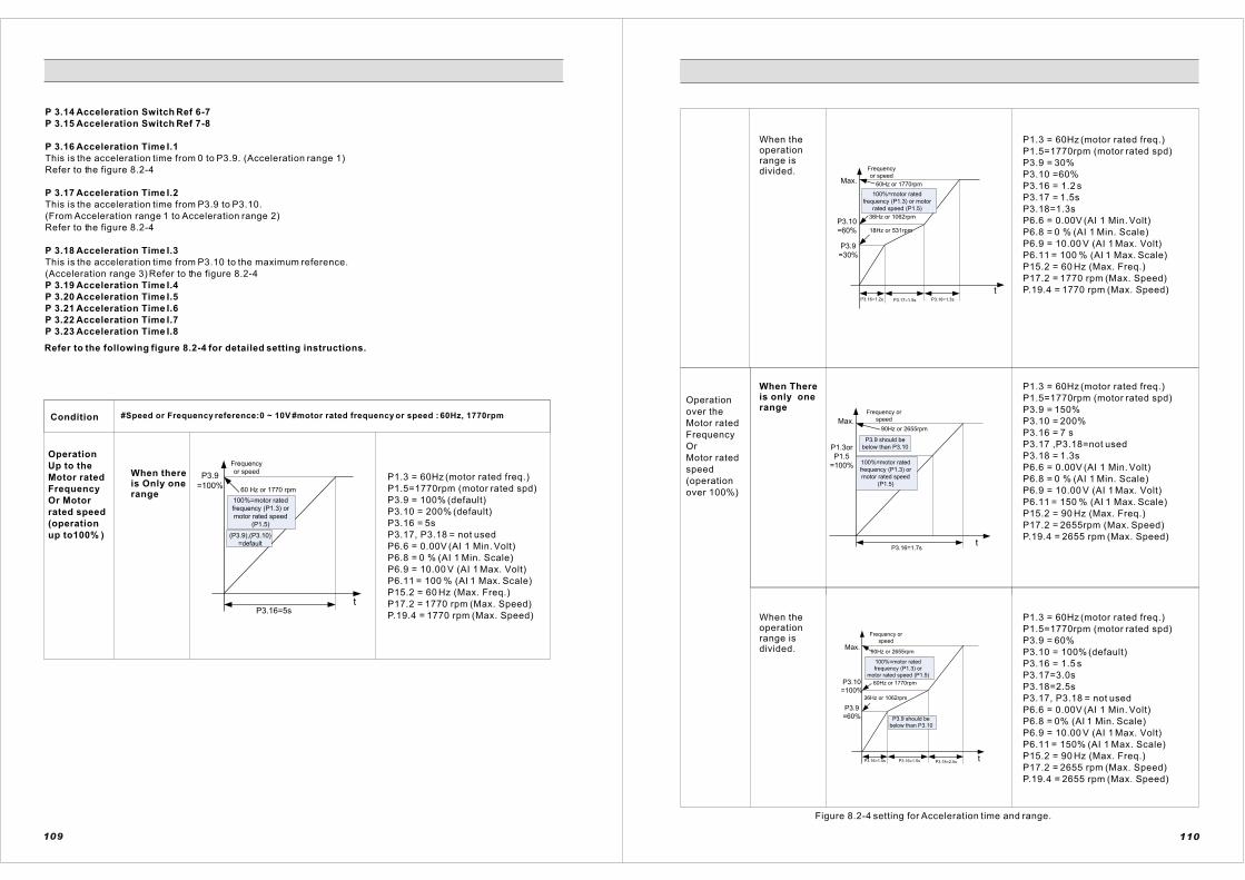
P 3.14 Acceleration Switch Ref 6-7
P 3.15 Acceleration Switch Ref 7-8
P 3.16 Acceleration Time I.1
This is the acceleration time from 0 to P3.9. (Acceleration range 1)
Refer to the figure 8.2-4
P 3.17 Acceleration Time I.2
This is the acceleration time from P3.9 to P3.10.
(From Acceleration range 1 to Acceleration range 2)
Refer to the figure 8.2-4
P 3.18 Acceleration Time I.3
This is the acceleration time from P3.10 to the maximum reference.
(Acceleration range 3) Refer to the figure 8.2-4
P 3.19 Acceleration Time I.4
P 3.20 Acceleration Time I.5
P 3.21 Acceleration Time I.6
P 3.22 Acceleration Time I.7
P 3.23 Acceleration Time I.8
Refer to the following figure 8.2-4 for detailed setting instructions.
Frequency
or speedP3.9
=100%60 Hz or 1770 rpm
100%=motor rated
frequency (P1.3) or
motor rated speed
(P1.5)
(P3.9),(P3.10)
=default
P3.16=5st
Condition #Speed or Frequency reference:0 ~ 10V #motor rated frequency or speed : 60Hz, 1770rpm
Operation
Up to the
Motor rated
Frequency
Or Motor
rated speed
(operation
up to100% )
When thereis Only onerange
P1.3 = 60Hz (motor rated freq.)
P1.5=1770rpm (motor rated spd)
P3.9 = 100% (default)
P3.10 = 200% (default)
P3.16 = 5s
P3.17, P3.18 = not used
P6.6 = 0.00V (AI 1 Min. Volt)
P6.8 = 0 % (AI 1 Min. Scale)
P6.9 = 10.00 V (AI 1 Max. Volt)
P6.11 = 100 % (AI 1 Max. Scale)
P15.2 = 60 Hz (Max. Freq.)
P17.2 = 1770 rpm (Max. Speed)
P.19.4 = 1770 rpm (Max. Speed)
109
Max.
P3.10
=60%
P3.9
=30%
t
60Hz or 1770rpm
36Hz or 1062rpm
18Hz or 531rpm
P3.16=1.2s P3.17=1.5s P3.18=1.3s
Frequency
or speed
100%=motor rated
frequency (P1.3) or motor
rated speed (P1.5)
When theoperationrange isdivided.
P1.3 = 60Hz (motor rated freq.)
P1.5=1770rpm (motor rated spd)
P3.9 = 30%
P3.10 =60%
P3.16 = 1.2 s
P3.17 = 1.5s
P3.18=1.3s
P6.6 = 0.00V (AI 1 Min. Volt)
P6.8 = 0 % (AI 1 Min. Scale)
P6.9 = 10.00 V (AI 1 Max. Volt)
P6.11 = 100 % (AI 1 Max. Scale)
P15.2 = 60 Hz (Max. Freq.)
P17.2 = 1770 rpm (Max. Speed)
P.19.4 = 1770 rpm (Max. Speed)
Operation
over the
Motor rated
Frequency
Or
Motor rated
speed
(operation
over 100%)
When Thereis only onerange
P1.3 = 60Hz (motor rated freq.)
P1.5=1770rpm (motor rated spd)
P3.9 = 150%
P3.10 = 200%
P3.16 = 7 s
P3.17 ,P3.18=not used
P3.18 = 1.3s
P6.6 = 0.00V (AI 1 Min. Volt)
P6.8 = 0 % (AI 1 Min. Scale)
P6.9 = 10.00 V (AI 1 Max. Volt)
P6.11 = 150 % (AI 1 Max. Scale)
P15.2 = 90 Hz (Max. Freq.)
P17.2 = 2655rpm (Max. Speed)
P.19.4 = 2655 rpm (Max. Speed)
Max.
P1.3or
P1.5
=100%
tP3.16=1.7s
90Hz or 2655rpm
P3.9 should be
below than P3.10
Frequency or
speed
100%=motor rated
frequency (P1.3) or
motor rated speed
(P1.5)
Max.
P3.10
=100%
P3.9
=60%
t
90Hz or 2655rpm
60Hz or 1770rpm
36Hz or 1062rpm
P3.16=1.5s P3.16=1.5s P3.18=2.5s
Frequency or
speed
100%=motor rated
frequency (P1.3) or
motor rated speed (P1.5)
P3.9 should be
below than P3.10
When theoperationrange isdivided.
P1.3 = 60Hz (motor rated freq.)
P1.5=1770rpm (motor rated spd)
P3.9 = 60%
P3.10 = 100% (default)
P3.16 = 1.5 s
P3.17=3.0s
P3.18=2.5s
P3.17, P3.18 = not used
P6.6 = 0.00V (AI 1 Min. Volt)
P6.8 = 0% (AI 1 Min. Scale)
P6.9 = 10.00 V (AI 1 Max. Volt)
P6.11 = 150% (AI 1 Max. Scale)
P15.2 = 90 Hz (Max. Freq.)
P17.2 = 2655 rpm (Max. Speed)
P.19.4 = 2655 rpm (Max. Speed)
Figure 8.2-4 setting for Acceleration time and range.
110

P 3.24 Acceleration Time II
When DI Function is set to [14] Acc./Dec Switching, the value of Acceleration Time II is applied to the
Acceleration time from zero speed (or frequency) to the rated speed (or frequency) as DI receives the switching
signal.
P 3.25 Deceleration Time Range
[0] X 1 secretary
Use this option when the deceleration time is between 0 and 300 [s].
[1] X 10 sec
Use this option when the deceleration time is over 300 and goes up to 3000 [s].
(The deceleration time should be over 300.)
P 3.26 Deceleration Switch Ref 1-2
This is the frequency or speed reference that determines deceleration range 1
Refer to the figure 8.2-5
P 3.27 Deceleration Switch Ref 2-3
This is the frequency or speed reference that determines deceleration range 2
Refer to the figure 8.2-5
P 3.28 Deceleration Switch Ref 3-4
P 3.29 Deceleration Switch Ref 4-5
P 3.30 Deceleration Switch Ref 5-6
P 3.31 Deceleration Switch Ref 6-7
P 3.32 Deceleration Switch Ref 7-8
P 3.33 Deceleration Time I.1
This is the deceleration time from Max. reference to P3.27. (Deceleration range 3)
Refer to the figure 8.2-5
P 3.34 Deceleration Time I.2
This is the deceleration time from P3.27 to P3.26. (Deceleration range 2)
Refer to the figure 8.2-5
P 3.35 Deceleration Time I.3
This is the deceleration time from P3.26 to 0. (Deceleration range 1)
Refer to the figure 8.2-5
P 3.36 Deceleration Time I.4
P 3.37 Deceleration Time I.5
P 3.38 Deceleration Time I.6
P 3.39 Deceleration Time I.7
P 3.40 Deceleration Time I.8
Refer to the following figure 8.2-5 for detailed setting instructions.
111
“
“ ”
”
Condition #Speed or Frequency reference:0 ~ 10V #motor rated frequency or speed : 60Hz, 1770rpm
Operation
Up to t he
Motor rated
FrequencyOr
Motor rated
speed
(operation
up to100% )
When thereis Only onerange
Frequency or
speed
60Hz or 1770rpm
100%=motor rated
frequency (P1.3)or motor
rated speed (P1.5)
(P3.9),(P3.10)
=default
Max.
P3.33=5st
P1.3 = 60Hz (motor rated freq.)
P1.5 = 1770rpm (motor rated spd)
P3.26 = 100% (default-)
P3.27 = 200% (default)
P3.33 = 5s
P3.34, P3.35 = not used
P6.6 = 0.00V (AI 1 Min. Volt)
P6.8 = 0 % (AI 1 Min.Scale)
P6.9 = 10.00 V (AI 1 Max. Volt)
P6.11 = 100 % (AI 1 Max.Scale)
P15.2 = 60 Hz (Max. Freq.)
P17.2 = 1770 rpm (Max. Speed)
P.19.4 = 1770 rpm (Max.Speed)
60Hz or 1770rpmMax.
P3.35=1.3s P3.34=1.5s P3.33=1.2s
P3.27=60%
P3.26=30%
t
Frequency or
speed
100%=motor rated
frequency (P1.3)or motor
rated speed (P1.5)
When theoperationrange isdivided.
P1.3 = 60Hz (motor rated freq.)
P1.5 = 1770rpm (motor rated spd)
P3.26 = 30%
P3.27 = 60%
P3.33 = 1.2 s
P3.34 = 1.5s
P3.35 = 1.3s
P6.6 = 0.00V (AI 1 Min. Volt)
P6.8 = 0 % (AI 1 Min.Scale)
P6.9 = 10.00 V (AI 1 Max. Volt)
P6.11 = 100 % (AI 1 Max.Scale)
P15.2 = 60 Hz (Max. Freq.)
P17.2 = 1770 rpm (Max. Speed)
P.19.4 = 1770 rpm (Max. Speed)
Max. 90Hz or 2655rpm
P3.9 should be
below thanP3.10
60Hz or
1770rpm
36Hz or
1062rpm
P3.27
=100%
P3.26
=60%
P3.35=2.5s P3.34=3s P3.34=1.5s
t
Frequency or
speed
When theoperationrange isdivided.
P1.3 = 60Hz (motor rated freq.)
P1.5 = 1770rpm (motor rated spd)
P3.26 = 60%
P3.27 = 100%
P3.33 = 1.5 s
P3.34 = 3.0 s
P3.35 = 2.5 s
P6.6 = 0.00V (AI 1 Min. Volt)
P6.8 = 0% (AI 1 Min.Scale)
P6.9 = 10.00 V (AI 1 Max. Volt)
P6.11 = 150% (AI 1 Max.Scale)
P15.2 = 90 Hz (Max. Freq.)
P17.2 = 2655 rpm (Max. Speed)
P.19.4 = 2655 rpm (Max.Speed)
Figure 8.2-5 setting for Deceleration time and range
112
When thereis only onerange
P1.3=60Hz(motor rated freq)P1.5=1770rpm(motor rated spd)p3.26=150p3.27=200 default)p3.33=7sP3.17,P3.18=(not used)P6.6=0.00V(AI1VMin.Volt)P6.8=0 AI1Min .Scale)P6.9=10.00V(AI1V Max.Volt)P6.11=150 AI1 Max.Scale)P15.2=90Hz(Max.Freq)P17.2=2655rpm(Max.Speeq.)P19.4=2655rpm(Max.Speeq.)
Frequency or
speed90Hz or 2655rpm
(P3.9),(P3.10)
=default
Max.
P3.33=7st
60Hz or 1770rpm
P1.3
or
P1.5
=100
rpm
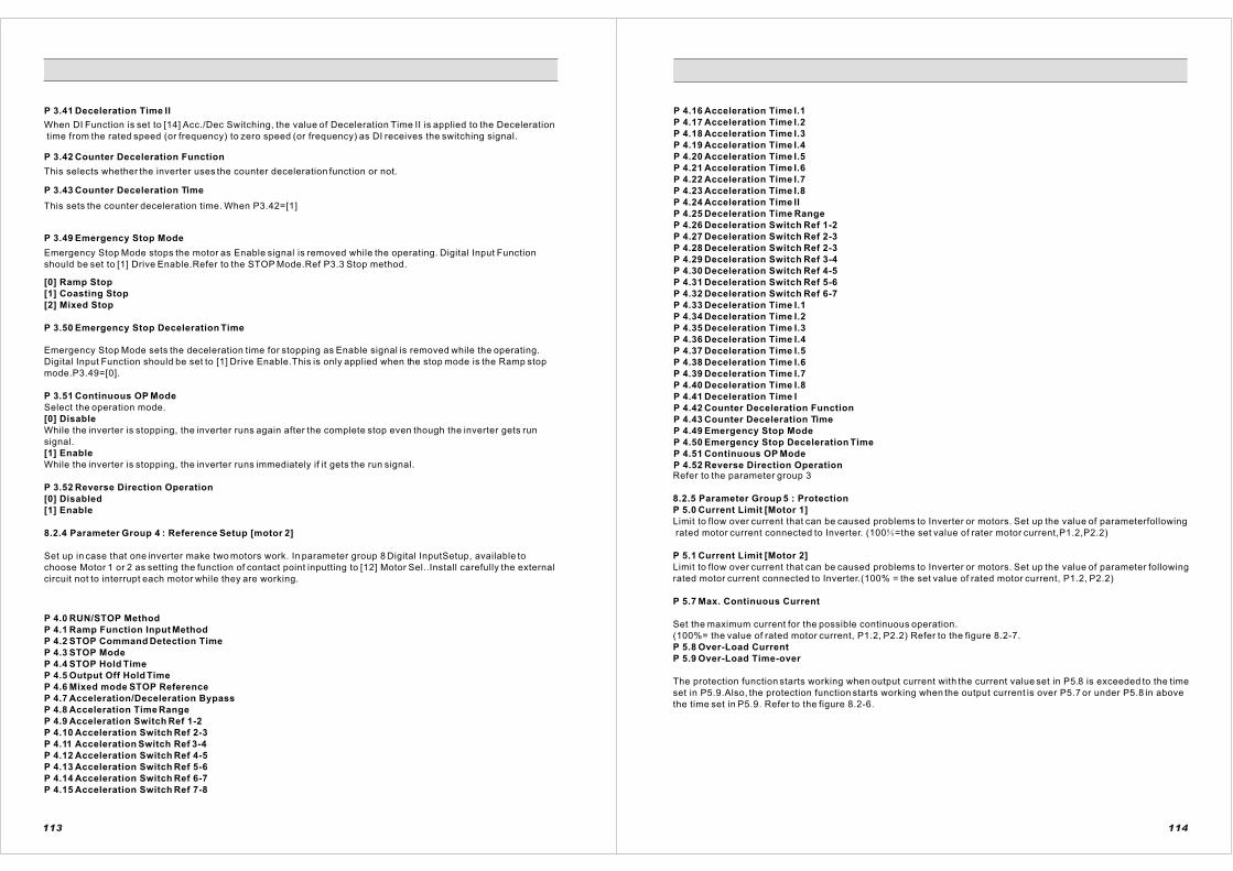
P 3.41 Deceleration Time II
When DI Function is set to [14] Acc./Dec Switching, the value of Deceleration Time II is applied to the Deceleration
time from the rated speed (or frequency) to zero speed (or frequency) as DI receives the switching signal.
P 3.42 Counter Deceleration Function
This selects whether the inverter uses the counter deceleration function or not.
P 3.43 Counter Deceleration Time
This sets the counter deceleration time. When P3.42=[1]
P 3.49 Emergency Stop Mode
Emergency Stop Mode stops the motor as Enable signal is removed while the operating. Digital Input Function
should be set to [1] Drive Enable.Refer to the STOP Mode.Ref P3.3 Stop method.
[0] Ramp Stop
[1] Coasting Stop
[2] Mixed Stop
P 3.50 Emergency Stop Deceleration Time
Emergency Stop Mode sets the deceleration time for stopping as Enable signal is removed while the operating.
Digital Input Function should be set to [1] Drive Enable.This is only applied when the stop mode is the Ramp stop
mode.P3.49=[0].
P 3.51 Continuous OP Mode
Select the operation mode.
[0] Disable
While the inverter is stopping, the inverter runs again after the complete stop even though the inverter gets run
signal.
[1] Enable
While the inverter is stopping, the inverter runs immediately if it gets the run signal.
P 3.52 Reverse Direction Operation
[0] Disabled
[1] Enable
8.2.4 Parameter Group 4 : Reference Setup [motor 2]
Set up in case that one inverter make two motors work. In parameter group 8 Digital InputSetup, available to
choose Motor 1 or 2 as setting the function of contact point inputting to [12] Motor Sel..Install carefully the external
circuit not to interrupt each motor while they are working.
P 4.0 RUN/STOP Method
P 4.1 Ramp Function Input Method
P 4.2 STOP Command Detection Time
P 4.3 STOP Mode
P 4.4 STOP Hold Time
P 4.5 Output Off Hold Time
P 4.6 Mixed mode STOP Reference
P 4.7 Acceleration/Deceleration Bypass
P 4.8 Acceleration Time Range
P 4.9 Acceleration Switch Ref 1-2
P 4.10 Acceleration Switch Ref 2-3
P 4.11 Acceleration Switch Ref 3-4
P 4.12 Acceleration Switch Ref 4-5
P 4.13 Acceleration Switch Ref 5-6
P 4.14 Acceleration Switch Ref 6-7
P 4.15 Acceleration Switch Ref 7-8
113
P 4.16 Acceleration Time I.1
P 4.17 Acceleration Time I.2
P 4.18 Acceleration Time I.3
P 4.19 Acceleration Time I.4
P 4.20 Acceleration Time I.5
P 4.21 Acceleration Time I.6
P 4.22 Acceleration Time I.7
P 4.23 Acceleration Time I.8
P 4.24 Acceleration Time II
P 4.25 Deceleration Time Range
P 4.26 Deceleration Switch Ref 1-2
P 4.27 Deceleration Switch Ref 2-3
P 4.28 Deceleration Switch Ref 2-3
P 4.29 Deceleration Switch Ref 3-4
P 4.30 Deceleration Switch Ref 4-5
P 4.31 Deceleration Switch Ref 5-6
P 4.32 Deceleration Switch Ref 6-7
P 4.33 Deceleration Time I.1
P 4.34 Deceleration Time I.2
P 4.35 Deceleration Time I.3
P 4.36 Deceleration Time I.4
P 4.37 Deceleration Time I.5
P 4.38 Deceleration Time I.6
P 4.39 Deceleration Time I.7
P 4.40 Deceleration Time I.8
P 4.41 Deceleration Time I
P 4.42 Counter Deceleration Function
P 4.43 Counter Deceleration Time
P 4.49 Emergency Stop Mode
P 4.50 Emergency Stop Deceleration Time
P 4.51 Continuous OP Mode
P 4.52 Reverse Direction OperationRefer to the parameter group 3
8.2.5 Parameter Group 5 : Protection
P 5.0 Current Limit [Motor 1]
Limit to flow over current that can be caused problems to Inverter or motors. Set up the value of parameterfollowing
rated motor current connected to Inverter. (100 =the set value of rater motor current,P1.2,P2.2)
P 5.1 Current Limit [Motor 2]
Limit to flow over current that can be caused problems to Inverter or motors. Set up the value of parameter following
rated motor current connected to Inverter.(100% = the set value of rated motor current, P1.2, P2.2)
P 5.7 Max. Continuous Current
Set the maximum current for the possible continuous operation.
(100%= the value of rated motor current, P1.2, P2.2) Refer to the figure 8.2-7.
P 5.8 Over-Load Current
P 5.9 Over-Load Time-over
The protection function starts working when output current with the current value set in P5.8 is exceeded to the time
set in P5.9.Also, the protection function starts working when the output current is over P5.7 or under P5.8 in above
the time set in P5.9. Refer to the figure 8.2-6.
114

ON
P5.31 P5.31 P5.31 P5.31 P5.31T<30s T<30s T<30 x 3 T<30s T<30s
Frequency
Or Speed
Fault 1
Counter 1Fault 2
Counter2
Fault 3
Counter 3
Fault 1
Counter 1
Fault 2
Counter 2Fault 3
Counter 3
Stopping Retry
If n > P5.30,
Retry doesn`t work
and you should
reset fault with a
hand
If there is no fault
after retrying, the
counter is reduced
1sec per every 30
sec
RUN
P 5.19 Open Phase Protection
The inverter generates a fault when the open phase happens.
[0] Disable : Not use the open phase protection function
[1] Enable : Use the open phase protection function
P 5.20 Supply Frequency
The frequency of Input Voltage
P 5.21 Built-in DB(Dynamic Brake)
Select whether using brake chopper or not inside of Inverter. Unless the brake
chopper is installed, set up [0] Disabled
[0] Disable
[1] Enable
P 5.23 DB Start voltage
P 5.24 DB Full Voltage
P 5.25 Over-Heating Fault[Action]
Select the Over Heat Function when the fault conditions occur.
[0] STOP: Stopping Inverter in the mode set in P3.3 or P4.3.
[1] E-STOP
[2] Ctrl_Off: Stopping Free-Run.
[3] IGNORE: Keeping operation of Inverter Warning.
[4] SPEED_DOWN
P 5.30 Auto-Restart Count
This is for the case when users want to keep operating even though a protection is still working. After the output is
broke, the inverter starts again automatically if the condition for restarting is qualified. This parameter sets the
numbers how many times the inverter allows to restart. Refer to the figure 8.2.-8.
P 5.31 Retry Delay Time
This sets the minimum stand-by time until restarting even though cancellation conditions are qualified after a fault
occurs. Refer to the figure 8.2.-7.
P 5.32 Auto Reset (Over Current)
Determines whether the inverter uses the Auto-Reset function or not when Over Current Protection is working.
[0] Disable
[1] Enable
P 5.33 Auto Reset (Over Voltage)
Determines whether the inverter uses the Auto-Reset function or not when Over Voltage Protection is working.
[0] Disable
[1] Enable
P 5.34 Auto Reset (Under Voltage)
Determines whether the inverter uses the Auto-Reset function or not when Over Voltage Protection is working.
[0] Disable
[1] Enable
Figure8.2-7.Auto Retry Function
116
“”
Current [A]
OL limit
P5.8
Max. conti.
current
P5.7
t_1 P5.9 t_2
Continuous
current
t
Figure 8.2-6 Set up overload
P 5.10 Over Load Fault [Action]
Select Stop function when Over Load Fault occurs.
[0] Normal Stop : Stopping Inverter in the mode set in P3.3 or P4.3.
[1] STOP
[2] Ctrl_OFF
[3] IGNORE: Keeping operation of Inverter Warning.
P 5.11 Over Current Trip
The Fault occurs when the output exceeds the Over Current trip level.
(100%= the value of rated motor current, P1.2, P2.2)
P 5.12 Zero-sequence Current trip
If the current addition of the three phases is less than the set value, the protection starts working.
P 5.13 Over Voltage Limiting Function
Select whether it uses the Over Voltage Limiting Function or not.
[0] Disable : Not use the over voltage limiting function
[1] Enable: Use the over voltage limiting function
P 5.14 Over Voltage Limit
Set the output voltage that controls the Over Voltage Limiting Function in normal status. This operates as only
setting in P5.13="[1] Enable" If the Over Voltage Limiting Function is working on deceleration, the deceleration
time gets slower than the set value.
P 5.15 Over Voltage Trip
Determine when to start the Over Voltage Function.
P 5.16 Under Voltage Compensation
Determines whether it compensate or not for the Under Voltage case.
[0] Disable : Not use the under voltage compensation function
[1] Enable : Use the under voltage compensation function
P 5.17 Under Voltage Compensation Limit
Determine the level of compensation for the Under Voltage case.
This operates as only setting in P5.16="[1] Enable".
When DC Link current is under the set value of the parameter, it prevents that the set value of DC Link current is
under the set value due to automatically adjusting output frequency or speed.
P 5.18 Under Voltage trip
Fault occurs if the inverter input voltage is below the Under Voltage Trip level.
115
error
error
error

P 5.37 Out of Control Auto Reset
The inverter can reset the functions with fault message when its status is out of control.
P 5.38 Out of Control Time
The inverter gives a fault when the time value of P5.39 is elapsed in out-ofcontrol status.
P 5.39 Out of Control Current
It is revised the amount of current in the state of out of control of Inverter.
100% of this parameter is the set value of Current Limit in P5.0 or P5.1.
As an example, when the set value of the rated motor current is 50[A] and the set value of Current Limit is 180%,
the current value is (50[A]x180%)x95%=85.5[A] with setting in P5.38 as 95% in the state of the out of control of
Inverter.
In case that P1.6 Control Mode is [0] V/F Freq or [1]V/F Speed.
If the output frequency is fewer than 5% of the rated motor frequency and the output current is generated over the
value set in P5.38 and these conditions are continued over the set time, Control Disable Fault occurs.
In case that P1.6 Control Mode is S/L or Vector Control.
If the standard value of speed and real value of speed have a difference, the output current is generated over the
value set in P5.38 and this condition is continued over the time set in P5.37, Control Disable Fault occurs.
P5.40 Over Temperature Trip
If output frequency of inverter exceeds by 45Hz while operating, overheat fault occurs when temperature on the
heat sink is evaluated over set value in P 5.40. If output frequency of inverter is less than 45Hz, the overheated
detection temperature of inverter can be changed as output current and output frequency in P5.40.
P5.41 Over Current Trip
8.2.6 Parameter Group 6 : Analog Input
P 6.0 Analog Reference Source
This case is only suitalole for P6.1(AI.1) .P6.15(AI.2).P6.29(AI.3).P6.43(AI.4).P6.57(AI.5)[1]Standard 1(r10
or[2]standarad 2(r2)
[0] Disable
Not use the Analog Input Terminals.
[1] AI 1
When Analog Input Function is set to [1] AI 1 in P6.1, the order value which is input to analog input terminal is
used as operation order signal.
[2] AI 2
When Analog Input Function is set to [1] AI 2 in P6.1, the order value which is input to analog input terminal is
used as operation order signal.
P 6.1 Analog Input 1 Function (Analog Input Function)
Selects the function of AI.1
[0] Disable
[1] AI 1
P 6.2 Analog Input 1 Type
Select the signal that is connected to AI.1 in analog input terminals.
[0]0-10(5)V
[1]-10~+10V: The direction of rotation is determined by polarity.
[2]4-20mA
[3]0-20mA
P 6.4 Analog Input 1 Filter Time Constant
Set the filtering time constant of the Analog Input reference. (For AI.1)
P 6.5 Analog Input 1 Offset adjustment
Set the Offset value of the Analog Input reference. (For AI.1)
P 6.6 Analog Input 1 min Voltage
P 6.7 Analog Input 1 min Current
P 6.8 Analog Input 1 Minimum
P 6.9 Analog Input 1 max. Voltage
P 6.10 Analog Input 1 max. Current
P 6.11 Analog Input 1 Maximum
Refer to the Figure 8.2-8.
117
P6.11
P6.8
P6.6
P6.7
0V0mA4mA
P6.9
P6.10
10V
20mA
Frequency
Or Speed
100%=rated motor speed
Or Rated frequency set value
Analog
input
P 6.12 Analog Input 1 Inversion
Determine whether the Analog Input reference from AI.1 is inverted or not.
[0] Disabled
[1] Enable
P 6.13 Analog Input 1 Discreteness
Divide steps up to the maximum frequency, and they have same output in the same steps. Overall, it is non-
continuous, but it can have the same output in the same step.
Figure 8.2-8 Setting the Analog Input Scale
0V0mA4mA
1-step
2-step
3 -step
4-step
5-step
6-step
7-step
8 -step16-step32-step64-step
128 --step
10V
20mA
Max speedMax Freq .
Anal oginput
Figure 8.2-9 Setting the Analog Input Step
118

P 6.14 Analog input 1 Dead-Zone
This is the zone that the inverter is not operating. If the analog input reference is smaller than the value of P6.6
or P6.7, the inverter does not generate the output even though the "RUN" signal comes in. Refer to the figure
8.2-10.
Frequency
or speed
Analog iuput
terminal reference
<P6.6 or P6.7
Analog input
terminal reference
P6.6 or P6.7
RUNON
Figure 8.2-10 The Dead-Zone of Analog Input.
P 6.15 Analog Input 2 Function
P 6.16 Analog Input 2 Type
P 6.18 Analog Input 2 Filter Time Const
P 6.19 Analog Input 2 Offset adjustment
P 6.20 Analog Input 2 min Voltage
P 6.21 Analog Input 2 min Current
P 6.22 Analog Input 2 Minimum
P 6.23 Analog Input 2 max. Voltage
P 6.24 Analog Input 2 max. Current
P 6.25 Analog Input 2 Maximum
P 6.26 Analog Input 2 Inversion
P 6.27 Analog Input 2 Discreteness
P 6.28 Analog input 2 Dead-Zone
Refer to the parameters from P6.1 to P6.14
P 6.29 Analog Input 3 Function
P 6.30 Analog Input 3 Type
P 6.32 Analog Input 3 Filter Time Const
P 6.33 Analog Input 3 Offset adjustment
P 6.34 Analog Input 3 min Voltage
P 6.35 Analog Input 3 min Current
P 6.36 Analog Input 3 Minimum
P 6.37 Analog Input 3 max. Voltage
P 6.38 Analog Input 3 max. Current
P 6.39 Analog Input 3 Maximum
P 6.40 Analog Input 3 Inversion
P 6.41 Analog Input 3 Discreteness
P 6.42 Analog input 3 Dead-Zone
Set the parameters when the option card is installed to your inverter.
Refer to the parameters from P6.1 to P6.14
119
P 6.43 Analog Input 4 Function
P 6.44 Analog Input 4 Type
P 6.46 Analog Input 4 Time Const
P 6.47 Analog Input 4 Offset Adjustment
P 6.48 Analog Input 4 min Voltage
P 6.49 Analog Input 4 min Current
P 6.50 Analog Input 4 Minimum
P 6.51 Analog Input 4 max. Voltage
P 6.52 Analog Input 4 max. Current
P 6.53 Analog Input 4 Maximum
P 6.54 Analog Input 4 Inversion
P 6.55 Analog Input 4 Discreteness
P 6.56 Analog input 4 Dead-Zone
Set the parameters when the option card is installed to your inverter.
Refer to the parameters from P6.1 to P6.14
P 6.57 Analog Input 5 Function
P 6.58 Analog Input 5 Type
P 6.59 Analog Input 5 Filter
P 6.60 Analog Input 5 Filter Time Const
P 6.61 Analog Input 5 Offset Adjustment
P 6.62 Analog Input 5 min Voltage
P 6.63 Analog Input 5 min Current
P 6.64 Analog Input 5 Minimum
P 6.65 Analog Input 5 max. Voltage
P 6.66 Analog Input 5 max. Current
P 6.67 Analog Input 5 Maximum
P 6.68 Analog Input 5 Inversion
P 6.69 Analog Input 5 Discreteness
P 6.70 Analog input 5 Dead-ZoneSet the parameters when the option card is installed to your inverter.
Refer to the parameters from P6.1 to P6.14
8.2.7 Parameter Group 7 : Process PID Control
PID can control processes by the amount of flowing water, airflow, pressure and etc.
PID Process Controller is added to the outside of speed control loop, so it can realize multi-functions
without using separate PID Controller or PLC.
Process PID Controller can be used by selecting [2] PID Process Control of P 3.1
Ana. Input
Panel
Set value
AI.1
AI.5
AI.1
AI.5
+P
I
D
Reference Ref. Mode
Reference1or
Reference2
Feedback 1orFeedback 2
Upper Limit
Lower Li mitLower Limit
Upper Li mit
Speed Ref.
Actualvalue
Figure 8.2-11. PID Control
120

P 7.0 PID Control Mode
[0] Disable
NOT use PID Function
[1] Process PID Control
This applies to the systems that are controlled by temperature, pressure, amount of water, height of water,
amount of wind and etc. Only forward operation is available in this control mode.
[2] Compensation PID Control
This is a PID Control for general purposes. In this mode, forward and reverse operations are available.
[3] Free Function PID
P 7.1 Reference Mode
Selects a reference input method when PID operation is used.
[0] Keypad
Set the reference of Process PID Controller by KEYPAD.
The range is from -100% to +100%.
[1] Fixed Value by Parameter Setting
[2] Analog Input Ref1
The reference of Process PID Controller uses the analog input value.
Use [1] Reference 1(r1) set in the analog input function of the parameter group 6.
[3] Analog Input Ref2
Use[2] Reference 2(r2) set in the analog input function of the parameter group 6.
[4] Free Function
P 7.2 Fixed Set-Point [Parameter]
The value in [1] of P7.1
P 7.3 Feedback Mode
Set the Analog input terminals of Feed back.
AI.1 and AI.2 can be selected by user's convenience. The input range is 0-10[V] or 0-20[mA] or 4-20[mA].
A option card is needed to use for AI.3 through AI.5.
[0] Ai1 feedback
Parameter Group 6.0: When [4] Feedback 1 of Analog Input function is set, F1 is only used for Feed back signal.
[1] AI 2 feedback
Parameter Group 6.0: When [5] Feedback 2 of Analog Input function is set, F2 is only used for Feed back signal.
[2] Free Function
Parameter group6.0:Both [4]feedback1(f1)and[5]feedback2(f2)Were set ,the two is used to feedback
signal.
P 7.4 Reference Sign Change
P 7.5 Feedback Sign Change
Change to opposite sign for reference of PID and feedback signal. (+ -> - and - -> +)
P 7.6 Control Period
Set the PID control Periods.
P 7.7 Proportional Gain
Set the proportional Gain for the PID Controller.
P 7.8 Integration Time
Set the integration Time for PID Controller.
The integrator is effective to remove the errors for the steady input, but it makes the whole system unstable. To
make the system stable, use the Proportion and Integration controller. If a user increases the proportional gain,
and decreases the integration time, the response gets faster, but the system is unstable. . If a user decreases
the proportional gain, and increases the integration time, the response get slower. This is the time that takes to
the 100% output level when there is 100% error between reference and the actual value.
P 7.9 Differential Time Constant
Set the differential time constant.
P 7.10 Feed-forward Gain
Set the gain that generates proportional output to the setting value.
121
P 7.11 Zero-Shift Factor 1
This is used to reduce the over shoot in transient response of PID output. If this parameter is 100%, there could
be over shoot for the PID Gain. In that case, reduce the value of this parameter to reduce the over shoot.
P 7.12 Proportional Gain 2
P 7.13 Integration Time 2
P 7.14 Differentiator Time Constant 2
P 7.15 Feed-Forward Gain 2
P 7.16 Zero-Shift Factor 2
Refer to the P7.7 to P7.11
P 7.17 Output Inversion
This reverses the PID Output.
P 7.18 Integrator Lower Limit
P 7.19 Integrator Upper Limit
Set the lower and upper limit of the integrator.
P 7.20 Output Lower Limit
Set the lower limit of Integrator output and PID Controller output.
Set in percentage (%) of the maximum operating speed.
P 7.21 Output Upper Limit
Set the Upper limit of Integrator output and PID Controller output.
Set in percentage (%) of the maximum operating speed.
P 7.22 Output Scale
Adjust the output scale of the PID output.
P 7.23 Intergrator Ini Value
[0] Speed Set Value
[1] Torque Set Value
[2] torque Offset
[3] Torque Limit
P 7.24 Auto RUN/STOP
When the Auto Stop Delay time is elapsed with the condition of that PID output is below the Output Lower Limit
(P7.0=[1], the inverter stops automatically.
P 7.25 Auto STOP Delay Time
When output value is kept for the time that is set in P7.25 under output lower limit (P 7.20), the inverter is a
utomatically stopped.
P 7.26 Auto START Error Condition
When the number of PID errors that is set in P7.25 Auto Start Error condition is occurred, the inverter restarts
automatically.
P 7.27 Set Point Function
P 7.28 Feedback Function
8.2.8 Parameter Group 8 : Digital Input
Refer to the chapter 4 for the location of terminals.
P 8.0 Run/Stop Control
Set the function of DI1 and DI2.
[0] 1. FWD/2. REV
DI 1 -> FWD, DI 2 -> REV
DI 1 : Run signal & Forward
DI 2 : Run signal & Reverse
The first entering signal will have the priority.
[1] 1. RUN/2. DIR
DI 1 ->RUN, DI 2 -> DIR
DI 1 : Run signal.DI 2 : Open Forward Close Reverse
122
“ ”

P 8.1 DI 3 Function(teminal9)
P 8.2 DI 4 Function(timinal10)
P 8.3 DI 5 Function(timinal12)
P 8.4 DI 6 Function(timinal13)
P 8.5 DI 7 Function(timinal14)
P 8.6 DI 8 Function(timinal15)
It sets the Functions for Digital Input Terminals.
[0] None
Using the contact point input terminal is prohibited or is not.
[1] Drive En. (Drive Enable)
The signal is used for inverter operation ready.
[2] Multi-Step 0
Use the signal for Multi-Step 0.
[3] Multi-Step 1
Use the signal for Multi-Step 1.
[4] Multi-Step 2
Use the signal for Multi-Step 2.
[5] Multi-Step 3
Use the signal for Multi-Step 3.
[6] Fault Reset
Use the signal for releasing the faults.
[7] JOG
Use the signal for JOG run
[8] AI_REF_Active
In case of taking the Analog input signal from DI terminal, the Analog input signal is disregarded when the signal
[7] is taken in the set terminal.
[9] AI_Loc_REMOTE (AI_Local / Remote)
Use the signal for Local or Remote selection.
[10] Ext. Fault A (External Fault A)
Use the signal for external fault input.
[11] Ext. Fault B (External Fault B)
Use the signal for external fault input.
[12] Motor Sel. (Motor Selection)
Use the signal for motor selection.
Open = Select motor 1
Close = Select motor 2
[13] MB BRAKE STATE
Use the signal for activating the external Magnetic Brake.
[14] Accel/Decel (Acceleration/Deceleration Switching)
Use the signal for selecting the Acc./Dec. time 1 or 2.
[15] Ref_ Tuning [INC] (Reference Increment)
[16] Ref_ tuning [DEC] (Reference Decrement)
If a signal enters to the terminal, the reference value is increased or decreased. And then, if there is no signal,
the speed is continued. If a signal reenters to the terminal, the reference value is increased or decreased. The
speed re-operated after stopped is same speed as before stopped. If the power is turned off and then turned on
again, the speed is back the initial reference speed.
[17] Acc/Dec_Byp (Accel/Decel Bypass)
If a signal enters to the terminal, controller ignores the Acc./Dec. time.
[18] PID Cntl_Enable (PID Control Enable)
This decides whether PID is used or not by the terminal. This option can be used when P7.0(PID Control Mode)
is selected.
If PID is not used, the inverter receives references by the set condition of P3.0 and P3.1
[19]AUTO_PID (AUTO PID Mode)
This is the same as P7.23, and this is set by terminals.
[20]PID_Gain (PID Gain Selection)
If this terminal is activated, The gain constants of P7.7~P7.10 are used.
If the terminal is not activated, the gain constants of P7.12~P7.15 are used.
123
[21] RST_PID_INT (PID Integrator Reset)
This makes the output of integrator to zero.
[22] Trq_Ref Opt_Bypass
[23] Torque_Sign
[24] Torque_Output_Zero
[25] Timer_RUN Enable
[26] Slave_RUN Status
[27] Sync_Ctrl_Option_Bypass
[28] Flying_Start
[29] Disable Profibus
P 8.7 DI 9 Function
P 8.8 DI 10 Function
P 8.9 DI 11 Function
P 8.10 DI 12 Function
P 8.11 DI 13 Function
P 8.12 DI 14 Function
P 8.13 DI 15 Function
P 8.14 DI 16 FunctionThis is only used as installing option board.
P 8.15 Blank Time after Motor change
This is a waiting time when the motor is changed from Motor 1 to Motor 2 or from Motor 2 to Motor 1 by the terminal
function of [12] Motor Selection.
P 8.16 Reference Up/Down Time
This is the Acc./Dec. time for the terminal function of [15] Reference Increment and [16] Reference decrement.
P 8.17 Start Delayed JOG Detection
Set up the time that is delayed to recognize the JOG signal to run the Inverter.
After recognizing JOG signal, the operation is delayed as set time.
P 8.18 RUN Delay Time
Set up he time that is delayed to recognize the RUN signal to run the Inverter.
After recognizing RUN signal, the operation is delayed as set time.
P 8.19 Tmr_RUN Time
8.2.9 Parameter Group 9 : Multi-Step Reference [Motor 1]
These parameters set the multi-step speed and jogging speed for Motor 1.
P 9.0 JOG Reference
Set the Jogging reference in percentage of the motor rated speed.
P 9.1 P 9.15: Multi Step.1 Ref Multi Step.15 Ref
These parameters are used for the speed reference when the multi-step operation is used. If P9.16 is [0]Hz, set the
demanded frequency as each step. If P9.16 is [1]%, set the percentage(%) for the rated motor speed(frequency). If
there is no any multi-stage speed signal, the motor is operated with the reference of the analog or the minimum speed
1 2 3 4 5 6 7 8 9 10 11 12 1 3 14 15
Multi-step 0 ON X ON X ON X ON X ON X ON X ON X ON
Multi-step 1 X ON ON X X ON ON X X ON ON X X ON ON
Multi-step 2 X X X ON ON ON ON X X X X ON ON ON ON
Multi-step 3 X X X X X X X
Step
Input
124
ON ON ON ON ON ON ON ON

P 9.16 Unit Selection
[0] Percent [%]
[1] Frequency [Hz]8.2.10 Parameter Group 10 : Multi-Step Reference [Motor 2]
Set in case of operating two motors with one Inverter. Select Motor 1 or 2 with setting the contact function to
"[12] Motor Sel." in Group 8 "Digital Input Setup."
Install carefully external circuit to prevent that Motor 1 and 2 are not interrupted each other.
P 10.0 JOG Reference
P 10.1~P 10.15: Multi Step.1 Ref ~ Multi Step.7 Ref.
P 10.16 Unit Selection
Refer to the parameter group 9.
8.2.11 Parameter Group 11 : Analog Output Configuration
These parameters are related to Analog Output.
P 11.0 Analog Output 1 selection
Set the function of Analog output 1. Use the terminal number 17 and 18 on Control Board..
[0] Frequency (Output Frequency)
[1] Motor Speed
[2] Output Current (Motor Current)
[3] Drive Output Voltage
[4] Torque (Actual Torque)
[5] Power Out (Output Power)
[6] DC_L Volt (DC_Link Voltage)
[7] Free_Func Output
[8] Trim 0 mA
[9] Trim 4 mA
[10] Trim 20 mA
P 11.1 Analog Output 1 Type
Select the range of output signal from Analog output 1 terminal.
[0] 0 20mA
[1] 4 20mA
P 11.2 Analog Output 1 Adjustment 0 mA
First set P11.0 to [7] Trim 0mA, and then, adjust the value of this parameter until the output current becomes
0mA. This is for fine tuning.
P 11.3 Analog Output 1 Adjustment 4 mA
First set P11.0 to [8] Trim 4mA, and then, adjust the value of this parameter until the output current becomes
4mA. This is for fine tuning.
P 11.4 Analog Output 1 Adjustment 20 mA
First set P11.0 to [9] Trim 20mA, and then, adjust the value of this parameter until the output current becomes
20mA. This is for fine tuning.
P 11.5 Analog Output 1 Output at 20mA
Set the value of Analog output selection of P11.0 when the analog output is 20mA.
[0] Output Frequency = 100% = P1.1
[1] Motor Speed = 100% = P1.5
[2] Motor Current = 100% = P1.2
[3] Motor Voltage = 100% = P1.1
[4] Torque
[5] Power Output = 100% = P1.0
[6] DC Link Voltage
P11.6 A0.1 signal invesion
[0] disable
[1] enable
Use only when a option board is installed.
This is about parameter related to analog output 2, 3 (AO2, AO3).
Refer to P11.0 to P11.6
125
8.2.12 Parameter Group 12 : Digital Output
P 12.0 DO 1 Function
P 12.1 DO 2 Function
P 12.2 DO 3 Function
Select the Function of Digital Output.
[0] Disable / Aux_SW_Ctlr
Not use the Digital Output Function.
[1] Drive Ready
It is activated when the inverter operation is ready.
[2] Fault Out [A]
It is activated when a fault occurs.(Aterminal NO)
[3] Fault Out [B]
It is activated when a fault occurs. (Bteminal NC)
[4] DM_Brake (Motor Brake)
If the conditions of Brake control of Motor 1 meet the requirements, it is activated or inactivated.
[5] RUN / STOP STATUS
It is activated when inverter is operating.
[6] WARNING (Warning Status)
It is activated when a warning occurs.
[7] Direction
It is activated when reverse signal enters.
[8] JOG State (Jog Input State)
It is activated when Jogging signal enters.
[9] OV/OC/UV Limit (OV/OC/UV Limiting Function)
It is activated when Over Voltage limiting function or Over Current limiting Function is running.
[10] Free Function
P 12.3 DO 4 Function
P 12.4 DO 5 Function
P 12.5 DO 6 Function
P 12.6 DO 7 Function
P 12.7 DO 8 Function
Refer to P12.0~ P12.2
Option Board is needed to use these extra terminals.
8.2.13 Parameter Group 13 : Motor Brake Control
Set up the condition for controlling a brake, thronge DO terminal,when the brake is installed to a motor.
Use the contact output terminal set in [4] Motor Brake [5]AUxDM_Brake in the contact output function of the parameter 12.
P 13.0 B1 Locked State UP_ Reference
P 13.1 B1 Locked State DOWN_ Reference
P 13.2 B1 Brake OPEN Current
P 13.3 B1 Start Delay Time
P 13.4 B1 Brake Close Speed Set
P 13.5 B1 Brake Open Torque Build Time
1. Output Speed (Frequency) > P13.0 or P 13.1
2. Output Current > P13.2
3. Taking time after inputting RUN signal > P13.3
It is the taking time of which a brake is physically opened completely after entering a signal that opens the brake.
Apply an approximate value because this value is not correct in general.
If an output speed (frequency) is below the set value of this parameter, the contact output signal for controlling the
brake is off, and it lets the brake be closed.
126

Time>P13.5 set valueCurrent >P13.2 set value
Frequency orspeed
P13.3
DI.01DI.02
RUNON
ONOFF
Signal on (motor
break open)
Closing of signal of motor brake opening = closingDI.02DI.02
DI.01DI.02
RUN
ON
ONOFF
stop
OFF
speed<P13.4
Frequency orspeed
P13.0 orP13. 1
Start to increase thespeed (freq uency) of
motor
Figure 8.2-12 Motor Brake On-signal Figure8.2-13 Motor Brake Off-signal
P 13.6 B2 Locked State UP_Reference
P 13.7 B2 Locked State DOWN_Reference
P 13.8 B2 Brake OPEN Current
P 13.9 B2 Start Delay Time
P 13.10 M2 Brake Open Torque Build Time
P 13.11 M2_Brk_OPEN_Torque_Build_Time B2_Trq_Tm
It is the parameter when motor 2 is applied. Refer to P 13.0 ~ P 13.4
8.2.14 Parameter Group 14 : Auto Tuning Configuration
It is the parameter that sets necessary details for Auto Tuning.
P 14.0 Motor tuning Condition
It is a precondition for auto tuning a motor.
[1] Free Rotor: In the state that the motor has no any load or motor is available to open.
[2] Locked Rotor: In the state that the motor has a load or motor is unavailable to open.
P 14.1 Excitation Slip Frequency
Set up a slip frequency for motor tuning while the motor is stalled. Mark this with the percentage of a rated
slip frequency.
P 14.2 Min. Tuning Speed
Set up the minimum tuning speed in case of operating Speed Tuning
P 14.3 Max. Tuning Speed
Set up the maximum tuning speed in case of operating Speed Tuning
P 14.4 High Frequency Excitation Frequency
P 14.5 High Frequency Excitation Current
P 14.6 Starting Excitation Current
P 14.7 Low Speed Excitation Flux
8.2.15 Parameter Group 15 : V/F Control [Motor 1]
These are the V/F Control parameters for Motor 1
127
P 15.0 Torque Compensation
When V/F Control is used, generating torque could be weak. This parameter sets up the Torque Compensation
Method to in low frequency range for Motor 1.
[0] Manual
Manual Torque compensation selection
The output voltage is generated for compensation depending on the following parameters: P15.6, P15.7, P15.8,
P15.9, P15.10, and P15.11
[1] Auto
Automatic Torque Compensation selection (Recommended)
The output voltage for compensating torque is generated automatically depending on the load. In this case, only
excitation current is generated. The output current is increased if the load is increased. The parameters that are
related to the Manual torque compensation would be ignored excepting P 15.11 Maximum output voltage.
P 15.1 Min. Output Frequency
Set the minimum operating frequency
P 15.2 Max. Output Frequency
Set the maximum operating frequency
P 15.3 Torque Compensation Flux Current
Set up the Flux Current at DC(0 Hz) if P1.6=[1] V/F Speed Control or P15.0=[1]
Auto Compensation is used
P 15.4 Torque Compensation Time Const
Sets up the Torque compensation time constant if P1.6=[1] V/F Speed Control or P15.0=[1] Auto Compensation is
used
P 15.5 Speed Detection Time Constant
Sets up the time constant for detecting a motor speed if P1.6=[1] V/F Speed Control is used.
P 15.6 V/F Pattern
Set up the output voltage curve for the inverter output frequency
[0] Linear V/F Curve
It is used for the application of a constant torque. The inverter output voltage, from the speed of zero to the field
weakening point, changes in proportion to the output frequency. Refer to the Figure 8.2-19.
[1] Square V/F Curve
The output voltage, from the speed of zero to the field weakening point, changes into a square-law reduced curve for
the output frequency. It is used for the square-law reduced load like a fan or pump and etc. Refer to the Figure 8.2-19.
[2] Custom V/F Curve
The user's random curve can make a V/F curve appointing three points by user's own desire. Refer to the Figure
8.2-15.
[3] Free Function
P 15.7 Zero Frequency Voltage
Set up the output voltage at 0 Hz.
You can use it only when a manual torque compensation (P15.0 = [0]) or the V/F Frequency Control mode (P1.6 = [0]).
P 15.8 Mid. Frequency
Set up the mid-point frequency when using a user's random curve
You can use it only when a manual torque compensation (P15.0 = [0]) or the V/F Frequency Control mode (P1.6 = [0]).
voltage
Max.
voltage
Mid. voltage
Zero freq volt
user
linear
square
Mid. frequency Max. voltage Freq frequency
Fi eld weak ening
Figure 8.2-14 V/F Pattern
128

P 15.9 Mid. Frequency Voltage
Set up the output voltage at the mid point frequency when using the user's random curve. You can use it only
when a manual torque compensation (P15.0= [0]) or the V/F Frequency Control mode (P1.6 = [0]).
P 15.10 Max Voltage Frequency
Set up the frequency of which the maximum voltage is generated. You can use it only when a manual torque
compensation (P15.0 = [0]) or the V/F Frequency Control mode (P1.6 = [0]).
P 15.11 Max output Voltage
Set up the inverter output voltage in a frequency range of field weakening operation.
You can use it only when a manual torque compensation (P15.0 = [0]) or the V/F Frequency Control mode
(P1.6 = [0]).
P 15.12 Voltage Limiter
If this is enabled, the output voltage is limited by the value of P15.11
[0] Disable
The output voltage can be generated as long as the output voltage allows the input voltage. Limit is eliminated.
[1] Enable
The output voltage does not generate output more than the value set in P15.11 Max Output Voltage.
P 15.14 Square Curve Voltage Compensation
Compensate the output voltage to the percentage of the rated voltage on decelerating.
Torque compensation is only available to use in manual. (P15.0=[0]Manual)
P 15.15 Start DC Brake [Time]
Set up the time that generates braking current when starting When this parameter is set to 0, there will be no
braking current when starting.
P 15.16 Start DC Brake [Blank time]
Set up the acceleration time of braking current when starting. In case that there is braking current during the
high-speed rotation, inverter can generate the excitation current without an inverter trip for the set time.
P 15.17 Start DC Brake [Current]
Set up the amount of braking current to output when starting. (100% = P1.2)
P 15.18 Stop DC Brake [Time]
Set up the time that generates the braking current when stopping.
The set time is the sum total of 1 sec. for DC brake starting and time for DC brake hold. If the time sets less than
1 sec, only P15,21 occurs. There will be no braking current if this is set to 0.
P 15.19 Stop DC Brake Blanking Time [STOP]
Set up the acceleration time of the braking current when stopping
In case that the braking current is generated during the high-speed rotation, inverter can generate the excitation
current without an inverter trip during the set time.
P 15.20 Stop DC Brake Hold Current [STOP]
DC brake current occurs and set up the amount of DC braking current to output when stopping in P15.21.
P 15.21 Stop DC Brake Starting Current [STOP]
Set up the amount of the DC braking current when stopping. (100% = P1.2)
Occur for 1 second after the speed(frequence) order value of inverter is zero.
Figure 8.2-15 Set up DC Brake
(100%)=P1.2
Start DC brake
current =P15.7
Start DC brake
blanking time=P15.16
Start DC
brak ing t ime
=P15.16
DI.01DI.02
RUN ON
OFF STOP
(100%)=P1.2Stop DC brake
current=P15.21
(100%)=P1.2
STOP DC braking
hold t ime =P15.21
Stop bla nking
time=P15.19
Stop DC
brak ing t ime
=P15.18
1s
t
Figure 8.2-15 Set up DC Brake
129
P 15.22 CC Proportional-Gain
Set up the Proportional Gain that is used for the current controller
P 15.23 CC Integral-Gain Scale
Set up the Integral Gain that is used for the current controller
P 15.24 Stabilization Time Const
Set up the stabilization time constant for the stabilization controller.
The stabilization controller can reduce the resonance of motor or other unstable problems, which is automatic-
ally detected by the stabilization controller.
P 15.25 Stabilization Gain
Set up the Gain of the stabilization controller
P 15.26 Stabilization Limit
This sets the upper limit of control output for the stabilization controller. If the resonance of motor or other unstable
problems is not reduced, increase this value to remove the problems.
P 15.27 Unity Current Range: Freq
Set up the frequency of which the current controller starts to change in the range of filed weakening operation. It is set
automatically if you operate the auto-tuning function. This is used when the operation is in high speed over the rated
frequency, and this parameter is for controlling smooth current in high speed range.
Current
Current
limit
Const torque area
Field weakearea
Const power area
Const (power x speed) area
t
Current
limit
Figure 8.2-16 Operating unite current range
P 15.28 Over Current Control Gain (Acceleration)
This is applied when the motor is accelerating and in constant speed.
P 15.29 Over Current Control Gain (Deceleration)
This is applied when the motor is decelerating.
The controller reduces the frequency a little bit if the output current exceeds the current limit while accelerating or
decelerating or in constant speed. Then, it keeps increasing the output frequency trying not to exceed the current limit.
P15.28 and P15.29 determine the slope when the controller lowers the current.
8.2.16 Parameter Group 16 : V/F Control [Motor 2]
These are the V/F Control parameters for Motor 2
P 16.0 Torque Compensation
P 16.1 Min. Output Frequency
P 16.2 Max. Output Frequency
P 16.3 Torque Compensation Flux Current
P 16.4 Torque compen sation time
P 16.5 Speed detection time
P 16.6 V/F Pattern
P 16.7 Zero Frequency Voltage
P 16.8 Mid. Frequency
P 16.9 Mid. Frequency Voltage
P 16.10 Max Voltage Frequency
P 16.11 Max output Voltage
P 16.12 Voltage Limiter
P 16.14 Square Curve Voltage Compensation
P 16.15 Start DC Brake Time
P 16.16 Start DC Brake Blank time
P 16.17 Start DC Brake Current
P 16.18 Stop DC Brake Time
P 16.19 Stop DC Brake Blank Time
P 16.20 Stop DC Brake Current
P 16.21 Stop DC Brake Frequency
P 16.22 CC P-Gain
P 16.23 CC I-Gain Scale
P 16.24 Stabilization Time Const
P 16.25 Stabilization Gain
130
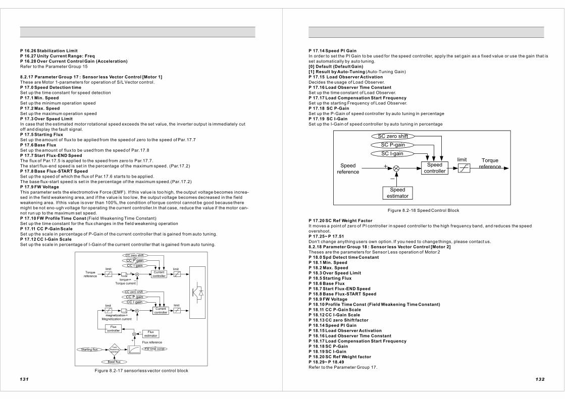
P 16.26 Stabilization Limit
P 16.27 Unity Current Range: Freq
P 16.28 Over Current Control Gain (Acceleration)
Refer to the Parameter Group 15
8.2.17 Parameter Group 17 : Sensor less Vector Control [Motor 1]
These are Motor 1-parameters for operation of S/L Vector control.
P 17.0 Speed Detection time
Set up the time constant for speed detection
P 17.1 Min. Speed
Set up the minimum operation speed
P 17.2 Max. Speed
Set up the maximum operation speed
P 17.3 Over Speed Limit
In case that the estimated motor rotational speed exceeds the set value, the inverter output is immediately cut
off and display the fault signal.
P 17.5 Starting Flux
Set up the amount of flux to be applied from the speed of zero to the speed of Par.17.7
P 17.6 Base Flux
Set up the amount of flux to be used from the speed of Par.17.8
P 17.7 Start Flux-END Speed
The flux of Par.17.5 is applied to the speed from zero to Par.17.7.
The start flux-end speed is set in the percentage of the maximum speed. (Par.17.2)
P 17.8 Base Flux-START Speed
Set up the speed of which the flux of Par.17.6 starts to be applied.
The base flux-start speed is set in the percentage of the maximum speed.(Par.17.2)
P 17.9 FW Voltage
This parameter sets the electromotive Force (EMF). If this value is too high, the output voltage becomes increa-
sed in the field weakening area, and if the value is too low, the output voltage becomes decreased in the field
weakening area. If this value is over than 100%, the condition of torque control cannot be good because there
might be not eno-ugh voltage for operating the current controller.In that case, reduce the value if the motor can-
not run up to the maximum set speed.
P 17.10 FW Profile Time Const (Field Weakening Time Constant)
Set up the time constant for the flux changes in the field weakening operation
P 17.11 CC P-Gain Scale
Set up the scale in percentage of P-Gain of the current controller that is gained from auto tuning.
P 17.12 CC I-Gain Scale
Set up the scale in percentage of I-Gain of the current controller that is gained from auto tuning.
CC P gain
CC I gain
FW time const
Base flux
Starting flux
Current
controller
Flux
controller Flux
estimator
CC P gain
CC I gain
Current
controller
Field
Weakening
operation
limit
limitlimit
limitTorque
reference
Flux reference
CC zero shift
torque >
Torque current
CC zero shift
megnetization >
Megnetization current
Figure 8.2-17 sensorless vector control block
131
P 17.14 Speed PI Gain
In order to set the PI Gain to be used for the speed controller, apply the set gain as a fixed value or use the gain that is
set automatically by auto tuning.
[0] Default (Default Gain)
[1] Result by Auto-Tuning (Auto-Tuning Gain)
P 17.15 Load Observer Activation
Decides the usage of Load Observer.
P 17.16 Load Observer Time Constant
Set up the time constant of Load Observer.
P 17.17 Load Compensation Start Frequency
Set up the starting Frequency of Load Observer.
P 17.18 SC P-Gain
Set up the P-Gain of speed controller by auto tuning in percentage
P 17.19 SC I-Gain
Set up the I-Gain of speed controller by auto tuning in percentage
SC zero shift
SC I-gain
Speed
controller
limitSpeed
reference
Speed
estimator
Torque
reference
SC P-gain
Figure 8.2-18 Speed Control Block
P 17.20 SC Ref Weight Factor
It moves a point of zero of PI controller in speed controller to the high frequency band, and reduces the speed
overshoot.
P 17.25~ P 17.51
Don't change anything users own option. If you need to change things, please contact us.
8.2.18 Parameter Group 18 : Sensor less Vector Control [Motor 2]
Theses are the parameters for Sensor Less operation of Motor 2
P 18.0 Spd Detect time Constant
P 18.1 Min. Speed
P 18.2 Max. Speed
P 18.3 Over Speed Limit
P 18.5 Starting Flux
P 18.6 Base Flux
P 18.7 Start Flux-END Speed
P 18.8 Base Flux-START Speed
P 18.9 FW Voltage
P 18.10 Profile Time Const (Field Weakening Time Constant)
P 18.11 CC P-Gain Scale
P 18.12 CC I-Gain Scale
P 18.13 CC zero Shift factor
P 18.14 Speed PI Gain
P 18.15 Load Observer Activation
P 18.16 Load Observer Time Constant
P 18.17 Load Compensation Start Frequency
P 18.18 SC P-Gain
P 18.19 SC I-Gain
P 18.20 SC Ref Weight factor
P 18.29~ P 18.49
Refer to the Parameter Group 17.
132

8.2.19 Parameter Group 19 : Vector Control 1 [Motor 1]
These are Motor 1- parameters for sensor vector control operation.
P 19.0 Number of Encoder Pulse
Set up the number of encoder pulse that is attached to an electric motor
P 19.1 Inversion of PG Direction
When a motor is running forward, this function makes the A or B phase go in advance. If the connection of A and
B phase is switched, or U, V and W phase are switched, this parameter can change the order of phase in
software without disconnect the real wires.
P 19.2 Speed Detect time Constant
Set up the time constant for detecting the motor rotation speed from encoder
P 19.3 Min. Speed
Set up the minimum operation speed
P 19.4 Max. Speed
Set up the maximum operation speed
P 19.5 Over speed Limit
In case that the motor rotation speed measured from encoder exceeds the set point, the inverter output is
immediately cut off and display a fault signal.
P 19.7 Starting Flux
Set up the amount of flux to be applied from the speed of zero to the speed set in Par.19.9
P 19.8 Base Flux
Set up the amount of flux to be applied from the speed set in Par.19.10
P 19.9 Start Flux-END Speed
The flux set in Par.19.7 is applied from the speed of zero to the speed set in Par.19.9. Set the start flux-end
speed in percentage of the maximum operation speed. (P19.4)
P 19.10 Base Flux-START Speed
Set up the speed that the flux of Par.19.8 starts to be applied
Set the base flux-start speed in percentage of the maximum operation speed
P 19.11 FW Voltage
This parameter sets the electromotive Force (EMF). If this value is too high, the output voltage becomes
increased in the field weakening area, and if the value is too low, the output voltage becomes decreased in the
field weakening area. If this value is over than 100%, the condition of torque control cannot be good because
there might be not enough voltage for operating the current controller.
In that case, reduce the value if the motor cannot run up to the maximum set speed.
P 19.12 FW Profile Time Constant
Set up the time constant for the flux change in the range of field weakening operation.
P 19.13 CC P-Gain (Current Control)
Set up the P-Gain of current controller by auto tuning in the percentage
P 19.14 CC I-Gain (Current Control)
Set up the I-Gain of current controller by auto tuning in the percentage
P 19.15 CC Ref Weight Factor(Current Control)
It moves a point of zero of PI controller in current controller to the high frequency band, and reduces the
overshoot of output current.
133
CC zero shift
CC P-gain scale
CC I-gain scale
Current
controller
CC zero shift
CC P-gain scale
CC I-gain scale
limit
limitlimit
limit
FC P-Gain Scale
FC I-Gain Scale
Torque ->
Torque
Current
Torque
reference
Load Comp
Load Comp Time
Load
compensator
Magnetization->
Magnetization
current
Flux
Controller
Flux
estimator
Flux reference
FW Time ConstField
weakening
operation
Basic Flux
Starting Flux
Current
Controller
Figure 8.2-19 vector control block
P 19.16 FC P-gain (Flux Control)
Set up the P-Gain of flux controller by auto tuning in percentage
P 19.17 FC I-Gain (Flux Control)
Set up the I-Gain of flux controller by auto tuning in percentage
P 19.18 Max. Field Current
Set up the limit for the maximum field current when starting
P 19.19 Speed PI Gain Selection
You can set up auto tuning in order to get PI Gain automatically to be used for speed controller
[0] Default Setting
[1] Result by Auto-Tuning
P 19.20 Load Observer
Set up the existence of torque compensation for a rapid load change
[0]= Disabled
[1] =Enable
P 19.21 Load Observer Time Constant
Set up the time constant for the torque compensation when there is a load change
P 19.22 SC Proportional Gain (Speed Control)
Set up the P-Gain of speed controller by auto tuning in percentage
P 19.23 SC Integral Gain (Speed Control)
Set up the I-Gain of speed controller by auto tuning in percentage
P 19.24 SC Ref Weight Factor(Speed Control)
It moves a point of zero of PI controller in speed controller to the high frequency band, and reduces the speed
overshoot.
134

CC Zero Shift
CC P-Gain Scale
CC I-Gain Scale
Speed
Controller
limit
Speed
reference
Speed of Motor
Torque reference
Figure 8.2-20 speed vector control block
8.2.20 Parameter Group 20 : Vector Control [Motor 2]
These are Motor 2- parameters for sensor vector control operation.
P 20.0 Number of Encoder Pulse
P 20.1 Inversion of PG Direction
P 20.2 Speed Detect time Constant
P 20.3 Min. Speed
P 20.4 Max. Speed
P 20.5 Over speed Limit
P 20.6 Flux Excitation Time
P 20.7 Starting Flux
P 20.8 Base Flux
P 20.9 Start Flux-END Speed
P 20.10 Base Flux-START Speed
P 20.11 FW Voltage
P 20.12 FW Profile Time Const
P 20.13 CC Proportional Gain (Current Control)
P 20.14 CC Integral Gain (Current Control)
P 20.15 CC Ref Weight Factor (Current Control)
P 20.16 FC P-gain (Flux Control)
P 20.17 FC I-Gain (Flux Control)
P 20.18 Max. Field Current
P 20.19 Speed PI Gain Selection
P 20.20 Load Observer Activation
P 20.21 Load Observer Time Constant
P 20.22 SC P-Gain (Speed Control)
P 20.23 SC I-Gain (Speed Control)
P 20.24 SC Ref Weight factor(Speed Control)
P 20.25~P20.41
Refer to the Parameter Group 19.
8.2.21 Parameter Group 21 : Motor 1 Parameter
These are the parameters that are automatically formed by Motor 1 auto-tuning
P 21.0 Stator Resistance 1
Set up the stator resistance 1 of a motor
P 21.1 Stator Resistance 2
Set up the stator resistance 2 of a motor
P 21.2 Rotator Resistance
Set up the rotator resistance of a motor
P 21.3 Stator Inductance
Set up the rotator stator rotator inductance of a motor
P 21.4 Rotator Indmctance
135
P 21.5 Leakage Inductance
Set up the leakage inductance of a motor
P 21.6 Inertia Time Constant
Set up the rotational inertia of a motor
P 21.7 Iron Loss Compensation
An iron loss impacts on the efficiency of control in the high-speed section. It can reduce controlling efficiency due to
the compensation for excessive loss or lack of loss. You can improve its function through adjusting the amount of iron
compensation.
P21.8 Biscos Damping Efficient
8.2.22 Parameter Group 22 : Motor 2 Parameter
These are the parameters that are automatically formed by Motor 2 auto-tuning.
P 22.0 Stator Resistance 1
P 22.1 Stator Resistance 2
P 22.2 Rotator Resistance
P 22.3 Stator Inductance
P 22.4 Rotor Inductance
P 22.5 Leakage Inductance
P 22.6 Rotational Inertia
P 22.7 Iron Loss Compensation
P 22.8 Biscos Damping Efficient
Refer to the Parameter Group 21
8.2.24 Parameter Group 24 : Monitor Setup
P 24.0 LCD Idle Time
A power of a keypad's backlight is cut off in case of the passage of a set time
P 24.1 LCD Contrast
Adjust the luminosity of a keypad's window
P 24.2 Key Repetition Time
The reaction time of a keypad's button
P 24.3 Speed Monitor Selection
[0] Calculation
The motor rotation speed that is displayed on a keypad indicates the calculated speed.
[1] Pulse Generator
The motor rotation speed that is displayed on a keypad indicates the actual rotation speed gained from encoder.
P 24.4 Speed Detection time Constant
In case of that the Speed Monitor Selection is set to Encoder, and this sets up the filtering time when measuring a
motor speed from encoder.
P 24.5 Monitor Filter Time Constant
Set the Filtering Time for the Keypad display values
P 24.6 Previous Run Direction
[0] Forward (Upward)
[1] Reverse (Downward)
P 24.7 Previous Speed Set
P 24.8 Previous Frequency Set
P 24.9 Previous Torque Set
P 24.10 Previous PID Set
P 24.12 Default Monitor Item
When inputting the main power to the Inverter, set the monitor items displayed initially on the keypad.
[0] Dc_Bus Voltage
[1] Line Voltage
[2] Line Frequency
[3] Line Current
[4] Active Power
[5] Reactive Power
[6] Power Factor
P 24.13 Left/Right Button Speed Set [Hz]
P 24.14 Left/Right Button Speed Set [rpm]
P 24.16 RS485 Station ID
136

9.1 warning
State Indication Specific ationType
WarningERR[Warning]*)These are onlyappliedto VDC PWM
W1 Under Volt UnderIf DC_Link Voltage is lower than theUnder-Voltage
AR2 DisableAnalog Reference 2 is not chosen in theAnalog Input Function of P6.1, P6.15 and P6.29.
Voltage Limit (P.5.18), the warning occurs.
W2 Over Volt[S] Over Voltage1If DC_Link Voltage exceeds theOver-Voltage limit (P.5.14), thewarning occurs (Software manages).
W3 Over Volt[H] Over Voltage2It happens when there is a detection ofOver Voltage by hardware.
W4 Sensor Error Sensor ErrorIt happens when there is a problem ofcurrent sensor & circuit..
W5 Over Load Over Load
This occurs if the output current satisfies the over-load condition of P5.8 and P5.9. If P5.10=[1] ignore, it doesn't occur.
W6 ZeroSeq. CurrZero sequence current
There is a detection of current leakage that exceeds P15.12 (ZC Trip).
W7 Over_Temp Over Temperature It happens when the temperature of heat sink of inverter exceeds 90.
W8 Device_Short Device ShortIt happens when there is a problem with aswitching device of inverter.(P5.40)
W9 Drv. DisableVD DriveDisable
It happens if there is no Enableinput signal from the digital inputterminal when Digital Input function is set to Drive Enable.
W10 AR1 Disable AR1 DisableAnalog Reference is not chosen in the Analog Input Function of P6.1, P6.15and P6.29.
W11 AR2 Disable
W12 Pre-Charging AF1 DisableAnalog Feedback 1 is not chosen in theAnalog Input Function of P6.1, P6.15 and P6.29.
W13 ReverseVD_13 AF2 DisableAnalog Feedback 2 is not chosen in theAnalog Input Function of P6.1, P6.15 and P6.29.
W14 Drive Cal.Drive CalibrationDisorder
It occurs after parameter initialization ofchanging switching Frequency. Execute by [0] Drive Calibration of Auto Tuning.
W15 ReverseVD_15 AR3 DisableAnalog Reference 3 is not chosen in theAnalog Input Function of P6.1, P6.15 and P6.29.
137
9.Protection
State Indication Specific ationType
W16 Drv_Cooling Drive Cooling
Once the inverter gets over-heated, the controller waits until the temperaturegoesdown above75?. Then, it continues operating.
W17 Tuning_Stop Auto TuningFailure
This means that Auto-tuning is not completed well. Any operation cannot beused with this warning. Turn-off the mainpower and then, turn it on again to use theoperation that does not need auto-tuning(etc. V/F). The drive Calibration must be executed. Reset the system to operateagain.
W18 M_Brk_not_Op Motor Brake not
When motor brake is used,MotorBrake=[4] this warning tells that the cond ition for.opening the motor brake is not qualified. In
Open this case, the speed is not accelerated.
W19 Ext_Fault External FaultThis tells that inverter gets the external fault signal when it is stopped.[10]Extemalfault(A)or[11]Extemal fault(B)
W20 Acc/Dec_BypV/F Accel/DecelBypass Error
Acceleration and deceleration time can be prohibited when V/F control is used. Over-Current Fault can be caused. If[17]Accel/Decel Bypass, the terminalfunction, is usedand V/F control is used, this warning can be generated. In V/F control, If frequency is changed withoutAccel.or Decel slop, the over-current canoccur.
W21 Low_OV_Limit Over Voltage Limit It happens when there is a setting errorin OV limit value.
W23 Slave Error Slave ErrorIt happens when there is an error fromslaves.
*)W24 Line_Seq_Err Line Sequence Err Line sequence error of VDC PWMconverter
*)W25 Line_UV Line Under Voltage It happens when there is Under Voltage.
*)W26 Line_Disconnection Line Unbalance It happens when there is Unbalanceinput
*)W27 LineOver-Voltage
Line ConnectionTest No fulfillment
It happens when there is Test Nofulfillment.
W28 Line Unbalance
W29 Line_ConnectionCheck
138
Voltage
W22 Syn Com_Errr

W30 Profibus Error
W31 UV Limiting
W32 OV Limiting
W33 OC Limiting
W34 OT Limiting
W35 Warning Logic 1
W36 Warning Logic 2
W37 Warning Logic 3
State
State
Indication
Indication
Specific ation
Specific ation
Type
Type
9.2 Errors
Parameter ErrERR[Pxx.xx]ParameterCombinationErrERR[Parameter]
ParameterCorruption
ParameterDamage
A flash memory of parameter is damaged.
kW / V/ A Mismatch
Output power,Voltage SettingErr
Setting error of rated output, rated voltage, and rated current of the motor
Hz/rpmMismatch
FrequencySetting Err
Setting error of Frequency,Speed, and number of poles of the motor
JumperSetting
Inverter Capacity Setting Err
Setting error of checking inverter power
ERR[Pxx.xx]ParameterSetting Err
A number of the parameter is indicated when there is aparameter setting error (Example: ERR[P2.1])
139
State Indication SpecificationType
Control FaultERR[Control]
F1 Over Load Over Load
It happens when output current ofinverter meets Over Load condition of P.5.7, P.5.8.
F2 Over Curr.OverCurrent [S]
It happens when output current ofinverter exceeds the set value ofP.5.9. (Software manages.)
F3 Over Curr.(H)OverCurrent [H]
A state of Over Current by hardware
F4 Zero Seq Curr.Zero-sequencecurrent [S]
It happens when Zero-phase-sequence current exceeds the set value of P5.12.
F5ZeroSeq Curr(H).
Zero-sequencecurrent [H]
A detection of Zero-phase-sequence current by hardware
F6 Under Current Under Current
It happens when output current ofinverter meets the condition of P.5.5, P.5.6 and so the current is unusually low.
F7 Over_Volt Over Voltage [S]
It happens when DC_Link voltage of the inside of inverter exceedsthe set value of P.5.15.(Software manages.)
F8 Over_Volt(H) Over Voltage [H]It happens when there is a detection of Over Voltage by hardware.
F9 Under_Volt Under Voltage
It happens when DC_Link voltage ofthe inside of inverter is lower than the set value of P.5.18. In case ofusing S/L Vector Control, it also happens when the connectionsbetween motor and inverter are cut.
F10 Over Speed Over-speedingMotor
It happens when the motor's rotatingspeed exceeds the speed that is set to P17.2(P.18.2, P.19.4, P.20.).
F11 Out of Ctrl Out of Control
It happens when a control conditionis not good due to internal and external factors; when a brake is not released; when a load is extremelybig; when an input signal does not gointo the encoder.
F21 Over_Temp OverheatedInverter
If the output frequency exceeds by45Hz and the heat sink exceedstemperature by set in P 5, 40, thefault occurs. If the output frequencyis less than 45Hz, overheat detectionvalue of inverter is changed by the output current and output frequency.It's necessary to keep watching theoutput frequency, current and temperature when a fault occurs.
F22 Device_Short IGBT/MOTORDevice_Short
It happens when there is a problem with a switching device of inverter.
9.3Fault
140

State Indication Specific ationType
F23Charging Err
Initial ChargeFault
It happens when you fail incharging the DC_link afteryou turn on the power.
F24Brake Damage
Dynamic Brake Chopper (DBR)Damage
It happens when DC_link voltage does not go up due to a problemof built-in Brake Chopper after youturn on the power. And it alsohappens when over current occurs or a device is damaged while Brake Chopper is at work.
F25 Ext_FaultSignal Inputof ExternalFault
It happens when a Fault signal is inputted from external device.
F26 Zero_CurrentFault ConnectionError of gate drive voltage
It happens when time passes theset time of P5.3 with no current inthe condition that P5.2=Enabled.
F27 Open Phase Open phaseFault
It happens when one of phases is broken or cut.
F28 Motor LockCapacitor BankDamage
It happens when there is a fault incapacitor bank.
F29 Keypad_Error Keypad Error It happens when keypad is notconnected well.
F30 Sync_Com_Err SynchronousCom. Error
It happens when synchronouscommunication has an error.
*)F31 Line_UVLine UnderVoltage
It happens when input is low.
*)F32 Line_Open Line UnbalanceIt happens when input is notstable.
*)F33 Line SequenceChange
Line OverVoltage
It happens when input is over the rated voltage.
F34 Line Over Voltage
F35 LineUnbalance
F36 Profibus Error
F37 Fault_Logic 1
F38 Fault_Logic 2
141
State Indication Specific ationType
F39Master_Emergency
F41Wrong Conn.
Motor ConnectionFault
It happens when a connection between inverter and motor is separated.
AutoTuningFaultERR[Tuning]
F42High_Freq Res
Motor TuningError 1
It happens when the gained valuefrom a process of Motor Tuninghas errors.
F43High_Freq Ind
Motor TuningError 2
It happens when the gained valuefrom a process of Motor Tuning haserrors.
F44 Stator Res [Rs] Motor TuningError 3
It happens when the gained valuefrom a process of Motor Tuning haserrors.
F45 Rotor Res [Rs] Motor TuningError 4
It happens when the gained valuefrom a process of Motor Tuning haserrors.
F46 Stator Ind [Ls] Motor TuningError 5
It happens when the gained valuefrom a process of Motor Tuning haserrors.
F47 Rotor Lnd [Lr] Motor TuningError 6
It happens when the gained valuefrom a process of Motor Tuning haserrors.
F48 Inertia [Jm] Motor TuningError 7
It happens when the gained valuefrom a process of Motor Tuning haserrors.
F49 Motor StallMotor is in a stall status
Auto Tuning fails because a motor is stalled.
F50 Tn_Time_OverAuto TuningTime Over
It happens when Auto Tuning timeis over.
10. Troubleshooting
Condition Check items Management
Whenthereis norotationof motor
Inverteroutputdoes notoccur.
Does the input voltageof inverter work properly
Check the input voltageof inverter (L1, L2, L3)
Is the KEYPAD of inverter on
Call anage when inverterdoes not get turned on, eventhough a contact of KEY PADis OK
Is the operation mode & Reference of inverter properly set?
Check a set value of parameter
Is an operation signal inputted tothe inverter
Check if an operation signal isproperly inputted
142
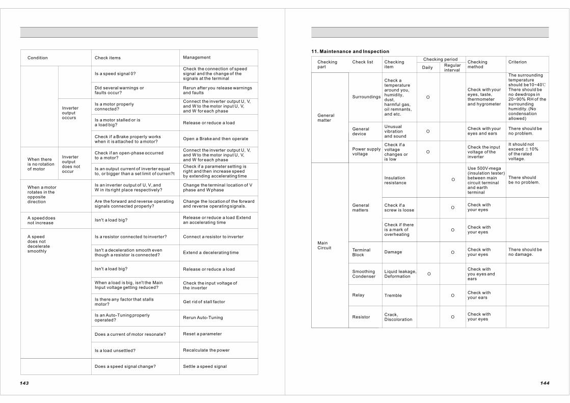
Condition Check items Management
Is a speed signal 0? Check the connection of speed signal and the change of thesignals at the terminal
Did several warnings orfaults occur?
Rerun after you release warnings and faults
Inverteroutputoccurs
Is a motor properlyconnected?
Connect the inverter output U, V,and W to the motor input U, V,and W for each phase
Is a motor stalled or isa load big? Release or reduce a load
Check if a Brake properly workswhen it is attached to a motor?
Open a Brake and then operate
When thereis no rotation of motor
Inverteroutputdoes notoccur
Check if an open-phase occurred to a motor?
Connect the inverter output U, V,and W to the motor input U, V,and W for each phase
Is an output current of inverter equal to, or bigger than a set limit of curren?t
Check if a parameter setting isright and then increase speed by extending accelerating time
When a motor rotates in the oppositedirection
Is an inverter output of U, V, and W in its right place respectively?
Change the terminal location of Vphase and W phase
Are the forward and reverse operatingsignals connected properly?
Change the location of the forwardand reverse operating signals.
A speed does not increase
Isn't a load big? Release or reduce a load Extendan accelerating time
A speeddoes notdeceleratesmoothly
Is a resistor connected to inverter? Connect a resistor to inverter
Isn't a deceleration smooth even though a resistor is connected?
Extend a decelerating time
Isn't a load big? Release or reduce a load
When a load is big, isn't the MainInput voltage getting reduced?
Check the input voltage of the inverter
Is there any factor that stallsmotor?
Get rid of stall factor
Is an Auto-Tuning properly operated?
Rerun Auto-Tuning
Does a current of motor resonate? Reset a parameter
Is a load unsettled? Recalculate the power
143
Does a speed signal change? Settle a speed signal
11. Maintenance and Inspection
Checkingpart
Check list Checkingitem
Checking period
DailyRegularinterval
Checkingmethod
Criterion
Generalmatter
Surroundings
Check a temperaturearound you,humidity,dust,harmful gas, oil remnants, and etc.
Check with your eyes, taste,thermometerand hygrometer
The surroundingtemperatureshould be10~40There should be no dewdrops in 20~90% RH of thesurroundinghumidity. (No condensationallowed)
Generaldevice
Unusualvibrationand sound
Check with your eyes and ears
There should be no problem.
Power supplyvoltage
Check if a voltagechanges oris low
Check the input voltage of the inverter
It should not exceed 10%of the rated voltage.
MainCircuit
Generalmatters
Insulationresistance
Use 500V-mega(insulation tester) between maincircuit terminaland earth terminal
There shouldbe no problem.
Check if a screw is loose
Check with your eyes
Check if thereis a mark ofoverheating
Check with your eyes
TerminalBlock
DamageCheck with your eyes
There should be no damage.
SmoothingCondenser
Liquid leakage,Deformation
Check with you eyes and ears
Relay TrembleCheck with your ears
ResistorCrack,Discoloration
Check with your eyes
O
O
O
O
O
O
O
O
O
144
O

Checkingpart
Check list Checkingitem
Checking period
DailyRegularinterval
Checkingmethod
Criterion
Cooling FanVibration,abnormalsound
Check with your ears
CoolingWater System
Dust, dirt Check with your eyes
WireDeformed, Check withStripped your eyes
InverterOutput
The 3 phase-output
Multi-meterVoltmeter
The 3-phase output has to be equal foreach phase.
Motor Vibration
Tightening It should be fine.
Output Currentof inverter
The 3-phase output has to be equal foreach phase.
Overheating Cooling FANcondition
There should be no disorder.
Main Circuit
ControlCircuit
OperationProtectivecircuit
Operate of your own accord
There should be no problem.
Connection Tightening Check with your eyes and hands
There should be no problem.
KEYPADIndication,workingcondition
Check with your eyes and hands
There should be no problem.
O
O
O
O
O
145 146
O
O
O
O

A. Closed Loop Application (Vector Control) Operation Procedure
146
R
S
T
MCCB
440Vac
M1 fuse 1
fuse 2
fuse 3
Reactor
(optional)
RFI
(optional)
TC1
RC1
220VacL1 L2 L3
+
-
Voltage
Reference
0~10V
5kO 2w
NO
1
2
3
4
5
6
7
8
9
10
11
12
13
14
15
16
17
18
19
20
21
22
23
24
25
26
Current
Reference
0(4)~20mAM2FWD
REV
R1
R3
R6
MS0
MS1
MS2
-
+
DO1
DO2
DO3
DO1.A
DO1.B
DO1.C
DO2.A
DO2.B
DO2.C
Vref.COM
Vref.+10V
AI 1.P
AI 1.N
AI 2.P
AI 2.N
DI.01
DI.04
DI.03
DI.02
DI.COM
DI.COM
DI.05
DI.06
DI.07
DI.08
AO1.N/DI.COM
AO.P
DO3.OC
DO3.24V
Brake
control
unitBrake
Use when brake
control is needed
U V W
M
22kW,440V,38.9A
60Hz 1770rpm 4pole
R-R+
THR
DBR
Brake chopper
(optional)
TC1
RC1
TC1
RC1
R1
R1 R2 R3 R4 R5 R6M2 GM1
fuse 1
fuse 2
fuse 3
R1
R2
R3
R4
THR R1DO
2DO
1
DO
3 R5
FWD REV 1N 2N 3N 4N 5N 7N6N MS0 MS1 MS2
1N 2N 3N 4N 5N 7N6NFWD REV
1N
2N3N
4N5N
7N 6N
2N
4N 6N
4N
AP
AN
BP
BN
Option
board
encoder
1000ppr
Use when applying vector control
(recommandation)
Line drive type1000ppr 24V
Refer to the
appendix A.2
connecting
*)Vin Reference + Multi Step Use
Refer to the chap. 7.4.3, item 1.
*) Iin Reference + Multi Step Use
Refer to the chap. 7.4.3, item 2.
L2 L3
description
Voltage reference group
10Vdc supply terminal
Analog input 1 terminal
0~10V use as volt. ref.
Analog input 2 terminal
0(4)~20mAuse as cur. Ref.
Forword run
Reverse run
Drive enable
External fault input
Digital input group
Fault reset
Mult-step 0
Mult-step 1
Mult-step 2
Digital input group
Analog output 0(4)~20mA
Digital output 3-open collector
Digital output +24V
Brake control
Fault output
speed
1
2
3
4
5
6
7
ON
DI.06 DI.07 DI.08
ON
ON ON
ON
ON ON
ON ON
ON ON ON
OFF OFF
OFFOFF
OFF
OFF OFF
OFF
OFF
HP vector
control
inverter
Master
controlfuse Thermal
relay
Main
power Brake
Use this when brake
control is needed
Ramp
ready
inverter
FaultFault
resetinverter
ready
Fault
resetMain sequence
diagram
Operation&mult-step
sequence diagram
speed
1
2
3
4
5
6
7
ON
DI.06 DI.07 DI.08
ON
ON ON
ON
ON ON
ON ON
ON ON ON
OFF OFF
OFFOFF
OFF
OFF OFF
OFF
OFF
Hoist brake have to be operated
with using by the brake control
relay of inverter .
(in case of PLC control , using
brake control relay makes safety
increase.)
A
Meter
Range 0~100A
Analog output 0(4)~20mA
terminal
147

A.2 Connecting Encoder to Option Board
P
N
A+
A-
B+
B-
NO.
105
106
107
108
AP
AN
BP
BN
Encoder Input
Voltage
(Table A.1)
Terminal
Line Drive E ncoder Option Board
NO.
105
106
107
108
terminal
AP
AN
BP
BN
P
N
A+
B+
Open col lec tor (NPN) enc ode Option board
Enc oder input Voltage
(Tab le A .1)
(1) Line Drive EncoderFor Line Drive Encoder, over 1024PPR is recommended. (24V)
(2) Open Collector (NPN) Encoder
Encoder
24V
15V
5V
S1 Dip-Switch Setting
1
OFF
ON
ON
2
OFF
OFF
ON
3
OFF
ON
ON
4
OFF
OFF
ON
S1 Dip-SwitchSetting
148
NO.
105
106
107
108
AP
AN
BP
BN
P
N
A+
B+
Terminal
Open collector (NPN) encodeOption board
Encoder input Voltage
(Table A.1)
(3) Open Collector (PNP) Encoder
NO.
105
106
107
108
AP
AN
BP
BN
P
N
A+
B+
Encoder input Voltage(Table A.1)
Terminal
Option boardOpen collector (NPN) encode
(4) Voltage Output Encoder
149

(5) Complemented Type Encoder
P
N
A+
B+
NO.
105
106
107
108
AP
AN
BP
BN
Terminal
Open collector (NPN) encode Option board
Encoder input Voltage
(Table A.1)
A.3 Motor Spec. and Setting of Closed Loop Control
Rated specification of the motor
RatedPower
R a t e dVoltage
22 kW
440 V
RatedCurrent
RatedFrequency
38.9 A
60 Hz
Rated Speed
Pole
1770rpm
4pole
Setting orderParameter Group D : Program Control
(1) Selecting Program
Parameter name Set Value DescriptionPar.Number
1 P 0.1 Program Boot Key 1 [1] Standard II Selecting software
2 P 0.2 Program Boot Key 2 [1] Standard II Selecting software
3 P0.3 Program Boot Key 3 Selecting software
Main Page [5] Initialize
4 M[5]-[1] "System Reset" Reset the inverter system
[1] Standard II
150
(2) Setting parameters for motor spec.
Setting orderParameter Group 1 : Control Setup[Motor 1]
Par.Number Parameter name Set Value Description
1 P 1. 0 Motor Rated Power 22 kW Rated Power of motor
2 P 1. 1 Motor Rated Voltage 440 V Rated Voltage of motor
3 P 1. 2 Motor Rated Current 38.9 A Rated Current of motor
4 P 1. 3 Motor Rated Frequency 60 Hz Rated Frequency of motor
5 P 1. 4 Number of Poles 4 Pole Number of Pole
6 P 1. 5 Motor Rated Speed 1770 rpm Rated Speed of motor
(3) Setting of motor Control Method (An encoder should be installed to the motor)When a Brake is not installed to the motor or it can be released while auto-tuning
Setting orderParameter Group1 : Control Setup[Motor 1]
Par.Number Parameter name Set Value Description
1 P 1. 6 Control Method[3] Vector SpeedControl
Vector Speed Control
Parameter Group 14 : Auto Tuning Configuration : Setting of Auto-Tuning
2 P14.0Motor TuningCondition
[0] Free Motor is not in stall condition.
Parameter Group 19 : Vector Control 1
3
4 M3-[2]
Execute the "Motor Tuning" (Refer to chapter 7.3)
Execute the "Speed Tuning" (Refer to chapter 7.3)
Move to "Chapter A.4 Speed reference and setting of Digital input"
When a brake is installed to the motor and it cannot be opened while auto-tuning(Auto Tuning = [2] Speed Tuning cannot be executed in this case)
Setting orderParameter Group1 : Control Setup[Motor 1]
Par.Number Parameter name Set Value Description
P 1. 61 Control Method[3] = Vector Speed Control
Vector Speed Control
Parameter Group 14 : Auto Tuning Configuration : Auto-Tuning Setting
2 P14.0Motor TuningCondition
[1] = Locked Motor is in stall condition
Setting orderParameter Group1 : Control Setup[Motor 1]
Par.Number Parameter name Set Value Description
3 M3-[1] Execute the "Motor Tuning" ( Refer to the chapter 7.3)
151
M3-[1]

Parameter Group 19 : Vector Control [Motor 1]
4 P19.19 Speed PI Gain [0] = Default Gain
Use Default values for PIGain of Speed ControlLoop P19.22, P19.23 can be adjusted for user's desire.
A.4 Speed Reference and Setting of Digital Input
This is the setting method to compose the system using analog input and Digital input like figure A-1 Basic Design. In this case, HPVFV inverter recognizes the Analog input as a speed reference if the multi-step digital input is not detected. If there is one or more multistep digital input is detected, the inverter automatically recognizes it as the speed reference.
(1) Parameter setting for Voltage (0[-10]~10V) reference + Multi-Step speed reference
Setting order
1
2
Parameter Group1 : Control Setup[Motor 1]
P 3. 0RUN/STOPMethod
[0] = Terminal RUN/STOP with DI.01 andDI.02
Par.Number Parameter name Set Value Description
P 3. 1 Reference Method [0] = TerminalUse Analog or Digital input forspeed or frequency reference
Parameter Group 6 : Analog Input Setup : Setting for Analog input
3
4
5
P 6. 0
P 6. 1
P 6. 2
Reference Mode
Analog Input 1 Function
Analog Input 1 Type
[1] = r1 only
[1] = reference 1
[0] = 0~10V
Use only r1 for analog input
Use r1 for Ai1
The type of speed reference Use0 ~ 10 V
Parameter Group 8 : Digital Input Setup : Setting for Digital input
6
7
8
P 8.0
P 8.1
P 8.2
RUN/STOP
DI.03 Function
DI.04 Function
[0] = FWD-DI.01REV - DI.02
[1] = Drive Enable
[9] = External Fault A Set DI.04 function to "External Fault A"
Set DI.03 function to "Drive Enable"
Setting digital input forRUN/STOP
Move to "chapter A.5 Setting of Digital output and Analog output"
9
10
11
12
P 8.3
P 8.4
P 8.5
P 8.6
DI.05 Function
DI.06 Function
DI.07 Function
DI.08 Function [4] = Multi Step 2
[3] = Multi Step 1
[2] = Multi Step 0
[5] = Fault Reset
Set DI.08 function to "multi step 2"
Set DI.07 function to "multi step 1"
Set DI.06 function to "multi step 0"
Set DI.05 function to "Fault Reset"
152
(2) Parameter setting for current(0[4]~20mA) input reference + Multi-step reference
Settingorder
Parameter Group1 : Control Setup[Motor 1]
Par.Number Parameter name Set Value Description
1
2
P 3. 0
P 3. 1
RUN/STOP Method
Reference Method
[0] = Terminal
[0] = Terminal
RUN/STOP with DI.01 andDI.02
Use Analog or Digital input forspeed or frequency reference.
Parameter Group 6 : Analog Input Setup : Setting for Analog input
3
4
6
P 6. 0
P 6. 15
P 6. 16
Reference Mode [1] = r1 only Use only r1 for analog input
Parameter Group 8 : Digital Input Setup : Setting for Digital input
P 8.0 RUN/STOP[0] = FWD DI.01REV DI.02
Setting digital input forRUN/STOP
7
8
9
10
11
12
P 8.1
P 8.2
P 8.3
P 8.4
P 8.5
P 8.6
DI.03 Function
DI.04 Function
DI.05 Function
DI.06 Function
DI.07 Function
DI.08 Function
[1] = Drive Enable
[10] = External Fault A
[6] = Fault Reset
[2] = Multi Step 0
[3] = Multi Step 1
[4] = Multi Step 2Set DI.08 function to "multi step 2"
Set DI.07 function to "multi step 1"
Set DI.06 function to "multi step 0"
Set DI.05 function to "Fault Reset"
Set DI.04 function to "ExternalFault A"
Set DI.03 function to "Drive Enable"
A.5 Setting of Digital Output and Analog Output
Settingorder
Parameter Group1 : Control Setup[Motor 1]
Par.Number Parameter name Set Value Description
Figure A-1 This is the setting method for digital output composition like basic design
1
2
P 11.0
P 11.1
AO 1 Output Selection [2] = Motor Current Set the Analog Output to"Motor Current"
[0] = 0~20mA
[1] = 4~20mA
Set the Analog Output range to"0~20mA"
Set the Analog Output range to"4~20mA"
5
153
AI.2 FunctionAI 2 Func
AI.2 TypeAI 2 Func
1
3
[0] Diisabled[1] Analog_In
[0] 0~10(5)V [1] -10~10V[2] 4~20mA [3] 0~20mA
AO.1 TypeAo1 Type
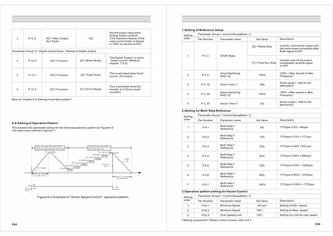
Set the output value when Analog Output is 20mA. (The maximum display of theused current meter in designis 100A, so set this to100)
3 P 11.5 AO.1 Max_OutputAo1 Scale
100
Parameter Group 12 : Digital Output Setup : Setting for Digital Output
4 P 12.0
P 12.1
P 12.2
5
6
DO 1 Function
DO 2 Function
DO 3 Function
[4] = Motor Brake
[2] = Fault Out A
[1] = Drive ReadyThis is activated when the inverter is in "Drive ready"condition.
This is activated when Faultoccurs. (A contact)
The Digital Output 1 is set to "brake control" (Refer to chapter 7.4.6)
Move to "chapter A.6 Setting of operation pattern"
A.6 Setting of Operation Pattern
This explains the parameter setting for the following operation pattern as Figure A-2.The basic input method is figure A-1.
A na l og re f e re nc e0~ 10V or 0(4)~20mA
Contact point input MS 0,MS 1,MS 2= OFF
Contact point input MS 0,MS 1,
MS 2= mo re t ha n1 ON
10s
P17.2= 1770rpm
A c ce l. tim e=P 3.16
P 17.2=60rpm
s pe e d1N
speed2N
spe ed3N
speed4N
speed5N
speed6N
speed7N
P 9.1=5%(88rpm)
P9.2= 10% (177rpm)
P9.3=30% (531rpm)
P9.4=50% (885rpm)
P9.5=70% (1239 rpm)
P9.6= 80% (1416rpm)
P9.7= 100 %(1770rpm)
Free -run
sto p
Ramp
stop
Run ON
stopDI.01
DI.02
OFF
D e c e l. time =P3.33
t12s
Figure A-2 Example of "Vector Speed Control" operation pattern.
154
1.Setting of Reference Setup
1 P 3. 3 STOP Mode
[0] = Ramp Stop Inverter controls the output untilthe motor stops completely after RUN signal is OFF.
Settingorder
Parameter Group1 : Control Setup[Motor 1]
Par.Number Parameter name Set Value Description
[1] = Free-Run StopInverter cuts off the outputimmediately as RUN signalis OFF.
2 P 3. 9Accel.SwitchingRef[1-2]
100%100% = Max. Speed or Max.Frequency
3 P 3. 16 Accel.Time I 1 10sAccel range 1 refer to thedescription
4
5
P 3. 26
P 3. 33
Decel.SwitchingRef[1-2]
Decel.Time I 1 12sDecel range 1 refer to thedescription
100% = Max. speed or Max.Frequency100%
2.Setting for Multi Step Reference
Settingorder
Parameter Group1 : Control Setup[Motor 1]
Par.Number Parameter name Set Value Description
1
2
3
4
5
6
7
P 9.1
P 9.2
P 9.3
P 9.4
P 9.5
P 9.6
P 9.7
Multi Step 1 Reference
Multi Step 1 Reference
Multi Step 1 Reference
Multi Step 1 Reference
Multi Step 1 Reference
Multi Step 1 Reference
Multi Step 1 Reference
5%
10%
30%
50%
70%
80%
100%
1770rpm X 5% = 88rpm
1770rpm X 10% = 177rpm
1770rpm X 30% = 531rpm
1770rpm X 50% = 885rpm
1770rpm X 70% = 1239rpm
1770rpm X 80% = 1416rpm
1770rpm X 100% = 1770rpm
3.Operation pattern setting for Vector Control
Settingorder
Parameter Group1 : Control Setup[Motor 1]
Par.Number Parameter name Set Value Description
1
2
3
P18.1
P18.2
P18.3
Minimum Speed
Over Speed Limit
Minimum Speed
60 rpm
100
125
Setting for Min. Speed
Setting for Max. Speed
Setting for Limit for over speed
<Setting completed!> If Brake control is used, refer to A.7
155

A.7 Setting the Brake Control Parameters Using Digital Output
This explains the related parameters when the brake is controlled using digital output as figure A-3 and A-4 like thebasic design of Figure A-1.
P13 .0 or P13.1
speed >0.6 Hz or 18 rpmcurrent >3.9 A
Fr eque ncy or
speed
t
Motor brake releasingsignal ON=open
0.3s
P13 .3RUNON
DI.01DI.02
DO.2
ONOFF
t
RUN
ON
ON
OFF
OFF
STOP DI.01
DI.02
DO.2
MO TOR Brake resealing signal OFF
speed <1.2Hz or 36rpm
P 13.4
Fr equen cy orspeed
Figure A-3 Brake open signal Figure A-4 Brake close signal
Settingorder
Parameter Group1 : Control Setup[Motor 1]
Par.Number Parameter name Set Value Description
1 P12. 1 DO.2 Function [4] = Motor Brake Set DO.2 to "motor brake"
Parameter Group 13 : Magnetic Brake Control : setting for motor brake control
2
3
4
P13.0
P13.1
P13.2
B1 Locked state Up_Ref
B1 Locked stateDown_Ref
B1 Open Current
Speed or frequency reference when digital output is ON.(60Hz,1770rpm) X 1% = 0.6Hz,18rpm
1%
1%
10%
The speed or frequency reference is kept for the set value of time.The time should be set dependingon the elapsed time until the brakeis opened completely after digital output is ON.
5 P13.3 B1 Open Response Time 0.3s
6
7
P13.4 B1 Close Reference 2%
Speed or frequency reference when digital output is OFF.(60Hz,1770rpm) X 2% = 1.2Hz, 36rpm
This is delay time until contactpoint output is turned into 'on',after inputting the operatingsignal. At this time, output current must be more than set value in P13.2
P13.5B1 Brake Open TorqueBuild Time
0.2s
<Digital output setting is completed for brake control>
156
B. Wiring Diagram for Crane ApplicationB.1 Hoist Motion (380V~460V / 5.5~200kW)
3phase power
supply
380~460V
50/60Hz
or 525~690V
50/60Hz
MCCB MCfuse ACL
RIF
filter
R
S
T
L1
L2
L3
M Internal
cooling fan
1k~10k 0.5W
Shield
cable
Overload relay trip contact
Braking resisitor unit1 2
P B
R1 R2
U
V
W
M
motor
1 10Vref
2 +10Vref:10Vdc
3 Vin1/Lin2+
4 Lin1-
5 Vin2/Lin2+
6 Lin2-
DI1
DI2
DI3
DI4
DI5
COM
DI6
DI7
DI8
COM
Multi-
function
contact
input
Shield
cable
Forward run/stop
Reverse run/stop
spare
External fault
Fault reset
Multi-step speed setting1
21
22
23
24
26
25
DO1.A
DO1.B
DO1.C
DO2.A
DO2.B
DO2.C
AC 1A/250V
DC 1A30V
AC 1A/250V
DC 1A30VFault contact
output
Brake contact output
(open&clsose)
Ready
relay
IC:max 1A
0(4)~20mA
17
18
20
19
24Vout
DC3
7
8
9
10
11
12
13
14
15
16
Multi-function analog
output
-10~10V 2mA
(output current)
Multi-step speed setting2
Multi-step speed setting3
Shield
cable
157
Do=NoSignal 38.9Ax10 =3.9A

B.2 Hoist Motion (380V~460V / 250~400kW)
MCCB MCfuse ACL
RFI
Filter
R
S
T
L1
L2
L3
MInternal
cooling
fan
1k~10k 0.5W
Shield
cable
Shield
cable
Overload relay
trip contact
Braking
resistor
unit
(option)
P
R
1
R
2
U
V
W
M
motor
1 10Vref
2 +10Vref:10Vdc
3 Vin1/Lin2+
4 Lin1-
5 Vin2/Lin2+
6 Lin2-
DI1
DI2
DI3
DI4
DI5
COM
DI6
DI7
DI8
COM
Multi-
function
contact
input
Shield
cable
Forward run/stop
Reverse run/stop
spare
External fault
Fault reset
Multi-step speed setting 1
21
22
23
24
26
25
DO1.A
DO1.B
DO1.C
DO2.A
DO2.B
DO2.C
AC 1A/250V
DC 1A30V
AC 1A/250V
DC 1A30VFault contact output
Brake contact iutput
(open &close)
Ready
relay
IC:max 1A
0(4)~20mA
1
7
1
8
20
19
24Vout
DC
3
7
8
9
10
11
12
13
14
15
16
Multi-function analog
-10~10V 2mA
(output current)
3 4
1 2
PP0
BBBraking
unit
(option)
Fuse FuseOverload relay
trip contact
Braking
resistor
unit
(option)
P
34
12
P P0
B B
R+ R-
Multi-step speed setting 2
Multi-step speed setting 3
158
B.3 Traversing & Traveling Motion (380V~460V / 5.5~200kW)
3phase power
supply
380~460V
50/60Hz
or 525~690V
50/60Hz
MCCB MCfuse ACL
RIF
filter
R
S
T
L1
L2
L3
M Internal
cooling fan
1k~10k 0.5W
Shield
cable
Overload relay trip contact
Braking resisitor unit1 2
P B
R1 R2
U
V
W
M
motor
1 10Vref
2 +10Vref:10Vdc
3 Vin1/Lin2+
4 Lin1-
5 Vin2/Lin2+
6 Lin2-
DI1
DI2
DI3
DI4
DI5
COM
DI6
DI7
DI8
COM
Multi-
function
contact
input
Shield
cable
Forward run/stop
Reverse run/stop
spare
External fault
Fault reset
Multi-step speed setting1
21
22
23
24
26
25
DO1.A
DO1.B
DO1.C
DO2.A
DO2.B
DO2.C
AC 1A/250V
DC 1A30V
AC 1A/250V
DC 1A30VFault contact
output
Brake contact output
(open&clsose)
Ready
relay
IC:max 1A
0(4)~20mA
17
18
20
19
24Vout
DC3
7
8
9
10
11
12
13
14
15
16
Multi-function analog
output
-10~10V 2mA
(output current)
Multi-step speed setting2
Multi-step speed setting3
Shield
cable
159
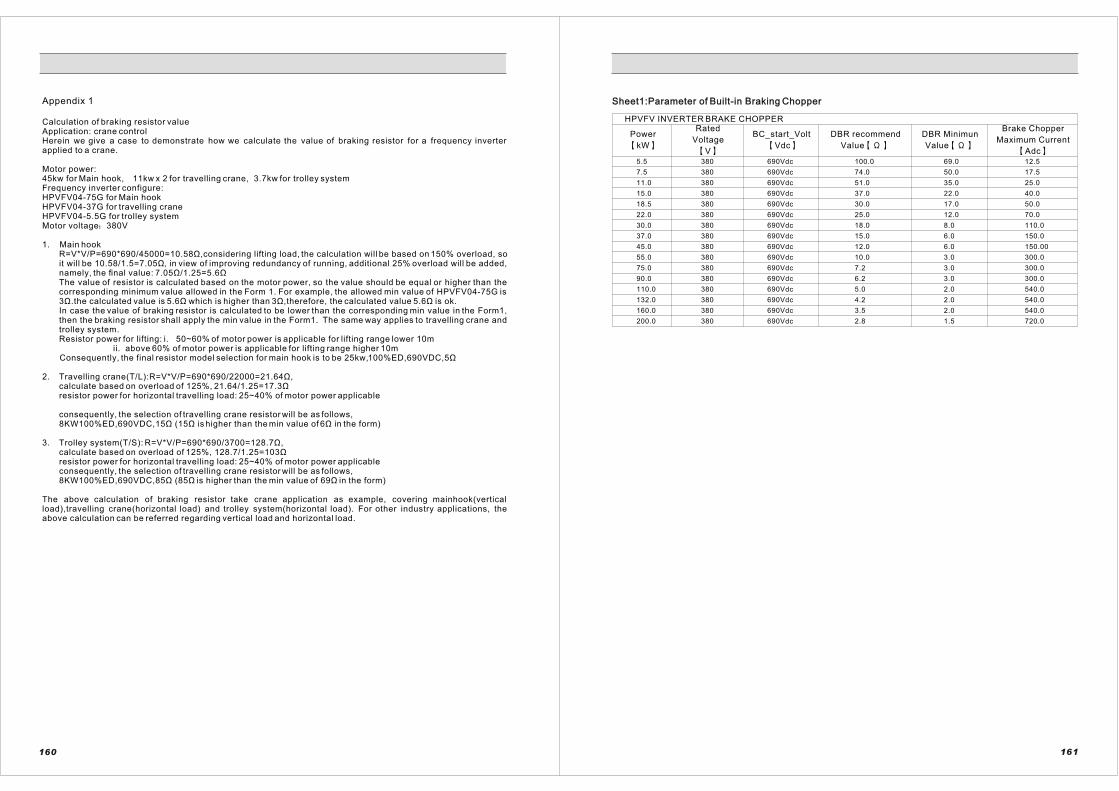
160 161
Appendix 1
Calculation of braking resistor value Application: crane control Herein we give a case to demonstrate how we calculate the value of braking resistor for a frequency inverter applied to a crane.
Motor power:45kw for Main hook, 11kw x 2 for travelling crane, 3.7kw for trolley systemFrequency inverter configure:HPVFV04-75G for Main hookHPVFV04-37G for travelling craneHPVFV04-5.5G for trolley systemMotor voltage 380V
1. Main hook R=V*V/P=690*690/45000=10.58Ù,considering lifting load, the calculation will be based on 150% overload, soit will be 10.58/1.5=7.05Ù, in view of improving redundancy of running, additional 25% overload will be added,namely, the final value: 7.05Ù/1.25=5.6ÙThe value of resistor is calculated based on the motor power, so the value should be equal or higher than thecorresponding minimum value allowed in the Form 1. For example, the allowed min value of HPVFV04-75G is3Ù.the calculated value is 5.6Ù which is higher than 3Ù,therefore, the calculated value 5.6Ù is ok.In case the value of braking resistor is calculated to be lower than the corresponding min value in the Form1, then the braking resistor shall apply the min value in the Form1. The same way applies to travelling crane andtrolley system.Resistor power for lifting: i. 50~60% of motor power is applicable for lifting range lower 10m ii. above 60% of motor power is applicable for lifting range higher 10m
Consequently, the final resistor model selection for main hook is to be 25kw,100%ED,690VDC,5Ù
2. Travelling crane(T/L):R=V*V/P=690*690/22000=21.64Ù,calculate based on overload of 125%, 21.64/1.25=17.3Ùresistor power for horizontal travelling load: 25~40% of motor power applicable
consequently, the selection of travelling crane resistor will be as follows,8KW100%ED,690VDC,15Ù (15Ù is higher than the min value of 6Ù in the form)
3. Trolley system(T/S): R=V*V/P=690*690/3700=128.7Ù,calculate based on overload of 125%, 128.7/1.25=103Ùresistor power for horizontal travelling load: 25~40% of motor power applicable consequently, the selection of travelling crane resistor will be as follows,8KW100%ED,690VDC,85Ù (85Ù is higher than the min value of 69Ù in the form)
The above calculation of braking resistor take crane application as example, covering mainhook(vertical load),travelling crane(horizontal load) and trolley system(horizontal load). For other industry applications, theabove calculation can be referred regarding vertical load and horizontal load.
Sheet1:Parameter of Built-in Braking ChopperSheet1:Parameter of Built-in Braking Chopper
HPVFV INVERTER BRAKE CHOPPER
Power
kW
Rated
Voltage
V
BC_start_Volt
Vdc
DBR recommend
Value
DBR Minimun
Value
Brake Chopper
Maximum Current
Adc5.5
7.5
11.0
15.0
18.5
22.0
30.0
37.0
45.0
55.0
75.0
90.0
110.0
132.0
160.0
200.0 380
380
380
380
380
380
380
380
380
380
380
380
380
380
380
380 690Vdc
690Vdc
690Vdc
690Vdc
690Vdc
690Vdc
690Vdc
690Vdc
690Vdc
690Vdc
690Vdc
690Vdc
690Vdc
690Vdc
690Vdc
690Vdc
100.0
74.0
51.0
37.0
30.0
25.0
18.0
15.0
12.0
10.0
7.2
6.2
5.0
4.2
3.5
2.8 1.5
2.0
2.0
2.0
3.0
3.0
3.0
6.0
6.0
8.0
12.0
17.0
22.0
35.0
50.0
69.0 12.5
17.5
25.0
40.0
50.0
70.0
110.0
150.0
150.00
300.0
300.0
300.0
540.0
540.0
540.0
720.0