39352E D9124 O&I Guide -...
64
D9124 EN Operation & Installation Guide Addressable 24 VDC Control Panel
Transcript of 39352E D9124 O&I Guide -...

D9124
ENOperation & Installation Guide
Addressable 24 VDCControl Panel

Bosch Security Systems | 11/03 | 39352E
EN | 2D9124 | Operation & Installation Guide |
NoticeThe material and instructions covered in this guide werecarefully checked for accuracy and are presumed to bereliable. However, Bosch Security Systems assumes noresponsibility for inaccuracies and reserves the right tomodify and revise this guide without notice.
It is our goal at Bosch Security Systems to alwayssupply accurate and reliable documentation. If adiscrepancy is found in this documentation, please maila photocopy of the corrected material to:
Bosch Security Systemsc/o Technical Marketing Department130 Perinton ParkwayFairport, NY 14450-9199 USA
© 2003 Bosch Security Systems, Fairport, NY USA. Allrights reserved.
Notice
Documentation ConventionsType Styles Used in this DocumentThe following type styles identify important items andobjects described in this guide.
Bold text - Indicates an important fact to note.
Italicized text - Refers to another part of this document oranother document entirely. It can also symbolize namesof user-created records.
Courier text - Indicates text that appears on theRemote Programming Software (RPS), command center,keypad, or an internal printer.
[CAPITALIZED TEXT] - Indicates the name of aspecific key to press.
Warnings, Cautions, and Important NotesThis document contains the following formattedwarnings, cautions, and important notes concerning theinstallation and/or programming of the unit.
Warning Notice – Warns of the possibility ofphysical damage to the operator and/orequipment. Used when there is an increaserisk of physical damage to the operator(severe injury or death) or equipment (as indestruction of physical components).
Caution Notice – Cautions the operatorabout physical damage to the programand/or equipment.
Important Note – Heed these notes forsuccessful operation and programming.Helpful tips and/or shortcuts can beincluded here.

EN | 3D9124 | Operation & Installation Guide |
Bosch Security Systems | 11/03 | 39352E
Contents
Contents
1. Introduction ............................................................... 71.2 Related Documents ................................................ 71.3 Document Organization ........................................ 71.4 FCC Rules ................................................................ 71.4.1 Part 15 ....................................................................... 71.4.2 Part 68 ....................................................................... 71.5 UL/NFPA Notices ................................................... 82. Overview ................................................................... 92.1 Specifications .......................................................... 92.2 Standard Features .................................................. 92.2.1 Protective Points ..................................................... 92.2.2 Communicator ......................................................... 92.2.3 24 VDC Outputs ..................................................... 92.2.4 Time and Date ......................................................... 92.2.5 Event Logger ............................................................ 92.2.6 Skeds (Scheduled Events) ................................. 102.2.7 Local Printer ........................................................... 102.2.8 EMI/Lightning Transient Protection ................. 102.2.9 Programming .......................................................... 102.2.10 Other Features ...................................................... 102.3 New Features in D9412G/D7412G ................ 102.3.1 Introduction ............................................................. 102.3.2 Ground Fault Detect ............................................ 102.3.3 Added Feature When Using Ground Fault
Detect ...................................................................... 102.3.4 NetCom Function .................................................. 103. Installation ............................................................... 113.1 Before You Begin .................................................. 113.1.1 Become Familiar with the Literature ................ 113.1.2 Become Familiar with the Components .......... 113.1.3 Determine the Battery Requirements .............. 113.2 Mounting the D9101 Enclosure ........................ 113.2.1 Flush Mounting ...................................................... 133.2.2 Surface Mounting ................................................. 133.3 Safety ....................................................................... 133.3.1 D9124 and High Voltage .................................... 133.3.2 Ground the System First ..................................... 133.3.3 Safety Precautions While Handling High
Voltage ..................................................................... 133.3.4 Safety Precautions While Handling
Batteries .................................................................. 133.4 Connecting the Earth Ground ........................... 143.4.1 Wire Connections to Earth Ground Stud ...... 143.4.2 Ground Fault Detect Enable .............................. 143.5 Installing the D1601 Transformer ..................... 153.6 Connecting the 120 VAC Power Input ........... 153.7 Installing Battery Shelves and Transformer
Cover ........................................................................ 163.8 Mounting the Components ................................. 163.8.1 D9100 Accessory Module Carrier .................... 163.8.2 Control Panel ......................................................... 163.8.3 Additional Modules ............................................... 16
3.9 Connecting Cables Between D9124 SystemComponents ........................................................... 17
3.10 Wiring Additional Modules ................................. 183.11 Turning on the Power ........................................... 184. Command Centers and Annunciation
Devices .................................................................... 194.1 Descriptions ............................................................ 194.1.1 D1255 and D1255R Command Centers ....... 194.1.2 D1256 Fire Command Center .......................... 194.1.3 D1257 Remote Fire Annunciator ......................204.2 Installing Command Centers and
Annunicators ..........................................................204.3 D1256/D1257 Specifications ........................... 215. Indicating Circuit (24 VDC Horns/Strobes/
Bells) ........................................................................235.1 Description ..............................................................235.2 Operation ................................................................235.3 Silence Switch ......................................................236. ZONEX, Addressable Points ..............................256.1 Description ..............................................................256.1.1 POPEX/POPIT Configurations ..........................256.2 Connecting the Additional D8125 Module ....256.3 Selecting POPIT Point Assignments ...............276.3.1 POPIT Labels .........................................................276.3.2 Program Record Sheet ........................................276.4 Installing POPITs ...................................................286.4.1 Routing the Data Cable ......................................286.4.2 Connect POPITS to the Data Cable ...............286.4.3 Connecting the D291S and D291M
Addressable Smoke Detector Bases ...............286.5 Connecting Data Loops to Terminals
on the Motherboard ..............................................286.6 Wiring the POPIT Sensor Loop ........................296.6.1 POPIT Displays ......................................................296.7 Central Station Reports ......................................306.7.1 BFSK Reporting ....................................................306.7.2 Modem IIIa2 Reporting .......................................307. Power Supplies ...................................................... 317.1 D9412GLTB, Command Center, and
Modules ................................................................... 317.1.1 Primary Power ........................................................ 317.1.2 Secondary Power .................................................. 317.2 24 VDC Initiating and Indicating Devices ......347.2.1 Primary Power ........................................................347.2.2 Secondary Power ..................................................348. Power Outputs .......................................................358.1 Auxiliary ....................................................................358.1.1 12 V Auxiliary Power from
D9412GLTB Terminal 1 ......................................358.1.2 24 VDC Power from Motherboard
Terminal 5 ................................................................358.2 Alarm Power Output for Indicating Circuits ...358.2.1 24 VDC Output Terminals 7 and 9 ..................358.2.2 Alarm Power Output Responses .......................35
Bosch Security Systems | 11/03 | 39352E
EN | 4D9124 | Operation & Installation Guide | Contents
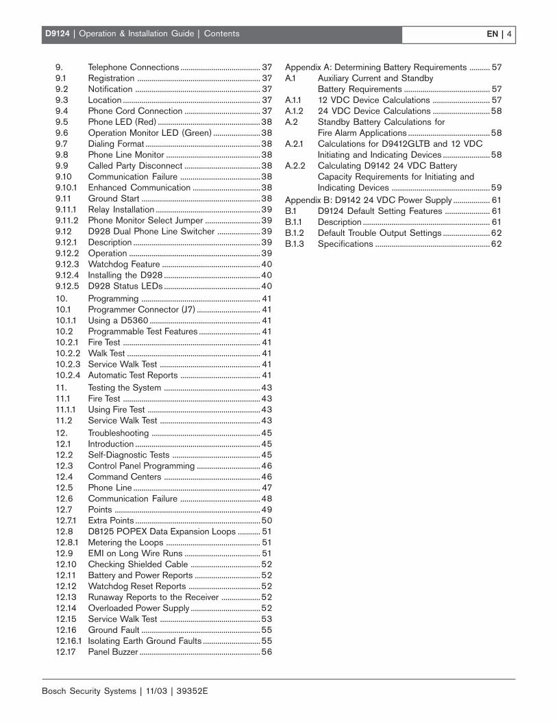
9. Telephone Connections ....................................... 379.1 Registration ............................................................ 379.2 Notification ............................................................. 379.3 Location ................................................................... 379.4 Phone Cord Connection ..................................... 379.5 Phone LED (Red) ..................................................389.6 Operation Monitor LED (Green) .......................389.7 Dialing Format ........................................................389.8 Phone Line Monitor ..............................................389.9 Called Party Disconnect .....................................389.10 Communication Failure .......................................389.10.1 Enhanced Communication .................................389.11 Ground Start ..........................................................389.11.1 Relay Installation ...................................................399.11.2 Phone Monitor Select Jumper ...........................399.12 D928 Dual Phone Line Switcher .....................399.12.1 Description ..............................................................399.12.2 Operation ................................................................399.12.3 Watchdog Feature ................................................409.12.4 Installing the D928 ...............................................409.12.5 D928 Status LEDs ...............................................4010. Programming .......................................................... 4110.1 Programmer Connector (J7) ............................... 4110.1.1 Using a D5360 ...................................................... 4110.2 Programmable Test Features .............................. 4110.2.1 Fire Test ................................................................... 4110.2.2 Walk Test ................................................................. 4110.2.3 Service Walk Test ................................................. 4110.2.4 Automatic Test Reports ....................................... 4111. Testing the System ...............................................4311.1 Fire Test ...................................................................4311.1.1 Using Fire Test .......................................................4311.2 Service Walk Test .................................................4312. Troubleshooting .....................................................4512.1 Introduction .............................................................4512.2 Self-Diagnostic Tests ...........................................4512.3 Control Panel Programming ...............................4612.4 Command Centers ...............................................4612.5 Phone Line .............................................................. 4712.6 Communication Failure .......................................4812.7 Points .......................................................................4912.7.1 Extra Points .............................................................5012.8 D8125 POPEX Data Expansion Loops ........... 5112.8.1 Metering the Loops .............................................. 5112.9 EMI on Long Wire Runs ..................................... 5112.10 Checking Shielded Cable ..................................5212.11 Battery and Power Reports ................................5212.12 Watchdog Reset Reports ...................................5212.13 Runaway Reports to the Receiver ...................5212.14 Overloaded Power Supply ..................................5212.15 Service Walk Test .................................................5312.16 Ground Fault ..........................................................5512.16.1 Isolating Earth Ground Faults ............................5512.17 Panel Buzzer ...........................................................56
Appendix A: Determining Battery Requirements .......... 57A.1 Auxiliary Current and Standby
Battery Requirements .......................................... 57A.1.1 12 VDC Device Calculations ............................ 57A.1.2 24 VDC Device Calculations ............................58A.2 Standby Battery Calculations for
Fire Alarm Applications ........................................58A.2.1 Calculations for D9412GLTB and 12 VDC
Initiating and Indicating Devices .......................58A.2.2 Calculating D9142 24 VDC Battery
Capacity Requirements for Initiating andIndicating Devices ................................................59
Appendix B: D9142 24 VDC Power Supply .................. 61B.1 D9124 Default Setting Features ...................... 61B.1.1 Description .............................................................. 61B.1.2 Default Trouble Output Settings .......................62B.1.3 Specifications ........................................................62
EN | 5D9124 | Operation & Installation Guide |
Bosch Security Systems | 11/03 | 39352E
Contents
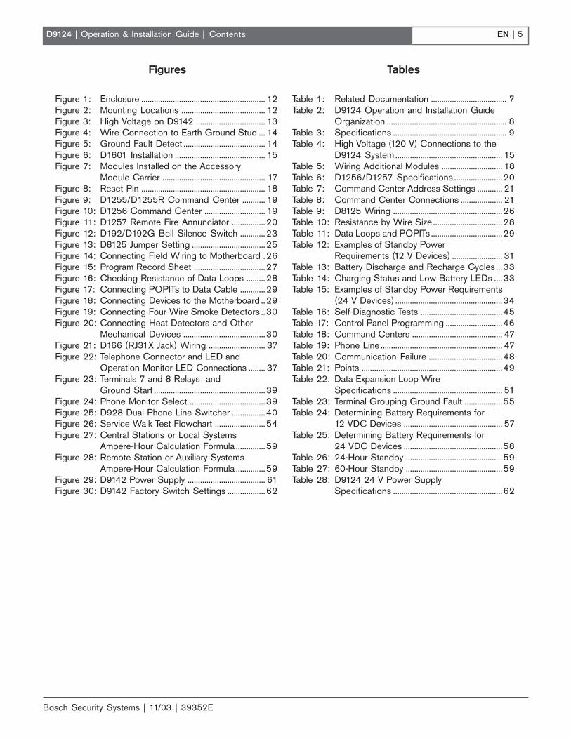
Figures
Figure 1: Enclosure ........................................................... 12Figure 2: Mounting Locations ........................................ 12Figure 3: High Voltage on D9142 ................................. 13Figure 4: Wire Connection to Earth Ground Stud ... 14Figure 5: Ground Fault Detect ....................................... 14Figure 6: D1601 Installation ........................................... 15Figure 7: Modules Installed on the Accessory
Module Carrier ................................................. 17Figure 8: Reset Pin ........................................................... 18Figure 9: D1255/D1255R Command Center ........... 19Figure 10: D1256 Command Center ............................. 19Figure 11: D1257 Remote Fire Annunciator ................20Figure 12: D192/D192G Bell Silence Switch ............23Figure 13: D8125 Jumper Setting ...................................25Figure 14: Connecting Field Wiring to Motherboard .26Figure 15: Program Record Sheet ..................................27Figure 16: Checking Resistance of Data Loops .........28Figure 17: Connecting POPITs to Data Cable ............29Figure 18: Connecting Devices to the Motherboard ..29Figure 19: Connecting Four-Wire Smoke Detectors ..30Figure 20: Connecting Heat Detectors and Other
Mechanical Devices .......................................30Figure 21: D166 (RJ31X Jack) Wiring ........................... 37Figure 22: Telephone Connector and LED and
Operation Monitor LED Connections ........ 37Figure 23: Terminals 7 and 8 Relays and
Ground Start .....................................................39Figure 24: Phone Monitor Select ....................................39Figure 25: D928 Dual Phone Line Switcher ................40Figure 26: Service Walk Test Flowchart ........................54Figure 27: Central Stations or Local Systems
Ampere-Hour Calculation Formula ..............59Figure 28: Remote Station or Auxiliary Systems
Ampere-Hour Calculation Formula ..............59Figure 29: D9142 Power Supply ..................................... 61Figure 30: D9142 Factory Switch Settings ..................62
Tables
Table 1: Related Documentation .................................... 7Table 2: D9124 Operation and Installation Guide
Organization ......................................................... 8Table 3: Specifications ...................................................... 9Table 4: High Voltage (120 V) Connections to the
D9124 System................................................... 15Table 5: Wiring Additional Modules ............................. 18Table 6: D1256/D1257 Specifications .......................20Table 7: Command Center Address Settings ............ 21Table 8: Command Center Connections .................... 21Table 9: D8125 Wiring ....................................................26Table 10: Resistance by Wire Size .................................28Table 11: Data Loops and POPITs ..................................29Table 12: Examples of Standby Power
Requirements (12 V Devices) ........................ 31Table 13: Battery Discharge and Recharge Cycles ...33Table 14: Charging Status and Low Battery LEDs ....33Table 15: Examples of Standby Power Requirements
(24 V Devices) ...................................................34Table 16: Self-Diagnostic Tests .......................................45Table 17: Control Panel Programming ...........................46Table 18: Command Centers ........................................... 47Table 19: Phone Line .......................................................... 47Table 20: Communication Failure ...................................48Table 21: Points ...................................................................49Table 22: Data Expansion Loop Wire
Specifications .................................................... 51Table 23: Terminal Grouping Ground Fault ..................55Table 24: Determining Battery Requirements for
12 VDC Devices ............................................... 57Table 25: Determining Battery Requirements for
24 VDC Devices ...............................................58Table 26: 24-Hour Standby ..............................................59Table 27: 60-Hour Standby ..............................................59Table 28: D9124 24 V Power Supply
Specifications ....................................................62

Bosch Security Systems | 11/03 | 39352E
EN | 6D9124 | Operation & Installation Guide | Contents
Notes:

EN | 7D9124 | Operation & Installation Guide |
Bosch Security Systems | 11/03 | 39352E
1. IntroductionThis guide addresses the operation and installation ofthe D9124 (D9412GLTB) Control Panel only, andshould not be used in conjunction with other panelsincluding the D9112B1 and D9112LTB-EX.
1.2 Related DocumentsA comprehensive list of all documents (with partnumbers) directly related to the D9124 Control Panel isprovided in Table 1. Throughout this manual, referencesare made to these documents. If it is necessary to obtainone (or more) of these documents, please contact BoschSecurity Systems Technical Support and request thedocument by its corresponding part number.
1.3 Document OrganizationThis document is divided into twelve sections and twoappendices as summarized in Table 2.
1. Introduction
Table 1: Related Documentation
Document Name Part NumberLiterature Pack
D9124 Operation & Installation Guide(this document)
39352
D9412G/D7412G Program EntryGuide
47775
D9124 Program Record Sheet 50098D9124 Release Notes 50097D1256 Fire System User’s Guide 71-06991-000SIA Information Booklet on SecurityAlarm Systems
71-05834-000
Technogram: Smoke DetectorsCompatible with the D9000/D7000Series Control/Communicators
33284
ZONEX Labels 74-04252-000ZONEX Labels 74-04252-003Point Chart Label* 79-06660-000
RPS Operations Manual 38849D6600 Computer Interface Manual 39963
* A Point Chart Label is required for fire systems withverification points. You must install the point chart label forfire or combined fire/burglary systems using verificationpoints.
Use the Program Record Sheet to gather the informationyou need to fill out the Point Chart Label. Install the labelinside the enclosure door. To avoid smearing your entrieson the chart, use the label’s peel off backing to press thelabel in place.
1.4 FCC Rules1.4.1 Part 15
This equipment was tested and complies with the limitsfor a Class B digital device, pursuant to Part 15 of theFederal Communication Commission (FCC) rules.These limits are designed to provide reasonableprotection against harmful interference in a residentialinstallation.
This equipment generates, uses, and can radiate radiofrequency energy; and if not installed in accordancewith the instructions, may cause harmful interference toradio communications. There is no guarantee thatinterference will not occur in a particular installation. Ifthis equipment does cause harmful interference to radioor television reception, which can be determined byturning the equipment on and off, the user is encouragedto try to correct the interference by one or more of thefollowing measures:
1. Reorienting or relocating the receiving antenna2. Increasing the separation between the equipment
and the receiver3. Connecting the equipment into an outlet on a
circuit different from that to which the receiver isconnected
4. Consulting the dealer or an experienced radio/TVtechnician for help
1.4.2 Part 68
This equipment complies with Part 68 of FCC rules.The label contents include the FCC registration numberand Ringer Equivalence Number (REN). If requested,this information must be provided to the telephonecompany.
The Bosch Security Systems D9124 24 VDCAddressable Fire System is registered for connection tothe public telephone network using an RJ38X or RJ31Xjack.
The REN determines the number of devices that can beconnected to the telephone line. Excessive devices onthe telephone line can result in one or more of thosedevices not ringing in response to an incoming call. Inmost, but not all areas, the sum of the RENs should notexceed five. To confirm the number of devices you canconnect to the line (as determined by the RENs) for thecalling area, contact the telephone company.
If the D9124 System harms the telephone network, thetelephone company will notify you or the customer assoon as possible. Also, you will be advised of your rightto file a complaint with the FCC.

Bosch Security Systems | 11/03 | 39352E
EN | 8D9124 | Operation & Installation Guide | 1. Introduction
Table 2: D9124 Operation and Installation Guide Organization
Section Description1 Introduction – Information about the structure and contents of this guide (this section).2 Overview – Overview of the 9124 Control Panel, including operational specifications, standards, and new features.3 Installation – Guide to the installation of the system with references to detailed instructions in later sections.4 Command Centers/Annunciation Devices – Describes the available command centers and their installation, wiring,
programming, and operation.5 Indicating Circuit – Information on available 24 VDC horns, bells, and strobes.6 ZONEX, Addressable Points – Information on the ZONEX points and their parameters including the installation,
wiring, and testing of POPEX modules and POPITs.7 Power Supplies – Information on supervision of the primary and secondary power supplies with instructions on
choosing and connecting secondary supplies.8 Power Outputs – Information on the available output power and the terminal connections required to use that power.9 Telephone Connections – Information on connecting the phone line(s) and programming the control panel for
reporting over the phone line(s).10 Programming – Instructions on programming the control panel.11 Testing the System – Description of and instructions for the Fire Test and the Service Walk Test.12 Troubleshooting – Solutions to a variety of commonly encountered problems.Appendix DescriptionA Determining Battery Requirements – Worksheets for determining the total power required, battery life, and standby
current requirements for common system applications including NFPA 72 Fire Alarm Applications.B D9142 24 VDC Power Supply – Description and specifications for the D9142 power supply including information
on battery supervision and status reporting.
The telephone company might make changes in itsfacilities, equipment, operations, or procedures that canaffect the operation of the equipment. If this happens,the telephone company will provide advance notice inorder for you to make the necessary modifications inorder to maintain uninterrupted service.
If you have trouble with the D9124 Control Panel,contact Bosch Security Systems Customer Service forrepair and/or warranty information. If the trouble iscausing harm to the telephone network, the telephonecompany might ask you remove the equipment from thenetwork until the problem is resolved. Do not makerepairs yourself; doing so voids your warranty.
This equipment cannot be used on public coin serviceprovided by the telephone company. Connection toParty Line service is subject to state tariffs. (Contactyour state public utilities commission for information.)
FCC Registration Number: AJ9MUL-46532-AL-ERinger Equivalence: 0.1BService Center in USA: National Repair Center
130 Perinton ParkwayFairport, NY 14450(585) 223-4220
1.5 UL/NFPA Notices
UL Listed for NFPA 72 Central Station, Local (non-coded), Auxiliary, Remote Station (DACT), Household
Fire Warning Systems. The D9124 System was approvedby FM, NYC-MEA, and CSFM.
The D9124 System is also listed for certificated centralstation (DACT) Grade B and Grade C burglaryapplications. Grade B systems require a local bell. TheD1255 Command Center must meet the UL CentralBurglary requirements.
All references to NFPA and related requirements arebased on compliance with the 1993 edition of NFPA 72,National Fire Alarm Code. Since installationspecifications are nearly always based upon a specificedition of a standard which was legally adopted by theAuthority Having Jurisdiction (AHJ), earlier editions ofNFPA standards generally apply. Consult theappropriate AHJ for confirmation.
Installation limits fall under the jurisdiction of the localauthority.
Initiating Circuits
The list below identifies the types of initiating circuitsthe control panel is approved for and theirabbreviations:
• Automatic (A)
• Manual (M)
• Waterflow (W)
• Sprinkler Supervisory (SS)

EN | 9D9124 | Operation & Installation Guide |
Bosch Security Systems | 11/03 | 39352E
2. Overview2.1 Specifications
2.2 Standard Features2.2.1 Protective Points
As shipped, the Bosch Security Systems D9124Addressable 24 VDC System provides eight on-boardpoints built into the control panel. On-board points 7and 8 support a 24 V power supply and notificationcircuits, and are not for other uses. As shipped, thecontrol panel can support 119 added Point of ProtectionInput Transponders (POPITs). If you use an additionalD8125 Point of Protection Expander (POPEX) Module,another 119 points can be added for a maximum total of246 (8+119+119).
2. Overview
Each point requires an addressable device for individualannunciation such as the D462, D291S, D291M, or aPOPIT. Each point is programmed separately withoptions to custom-fit the protection to your installation.Point programming parameters determine the system’sresponse to open and shorted conditions on the sensorloop.
2.2.2 Communicator
The D9124 Addressable 24 VDC System uses a built-indigital communicator to send reports to the receiver. Upto four receiver phone numbers can be programmed.You can program the control panel to send reports toprimary, backup, and duplicate phone destinations. Thecontrol panel transmits reports in Modem or BFSKformat. Use the Modem format to provide full systeminformation to the receiver.
The D9124 System connects to two D166 RJ31X (orRJ38X) jacks for phone line seizure. Connection to thejacks complies with FCC regulations for using thepublic telephone network. The D9124 System uses thebuilt-in D928 Dual Phone Line Switcher to supervisetwo phone lines.
2.2.3 24 VDC Outputs
The D9124 Control Panel provides a 24 VDC powersupply rated at 4 A. The operating voltage range of thisoutput is between 18.9 VDC and 28 VDC. All BoschSecurity Systems 24 V indicating devices are compatiblewith this power supply. For other indicating andinitiating devices, refer to the manufacturer’s InstallationInstructions . Verify the devices’ minimum operatingvoltage is equal to or greater than 18.9 VDC and themaximum operating voltage is equal to or less than28 VDC.
24 V indicating and initiating devices with aminimum operating voltage less than18.9 VDC or a maximum operating voltagegreater than 28 VDC can be damaged orfail to operate.
2.2.4 Time and Date
You need a D1255 Command Center or the D5500 RPSto set the time and date.
2.2.5 Event Logger
The D9124 System stores up to 1000 system events andevent modifiers in its Event Log. Event modifiers addinformation about an event to the log. Some events arealways followed by a modifier. For example, the D9124systems adds at least two items to the log each time itreports a phone line failure or keypad failure. It sendsthe event name and then an event modifier showing thenumber of the failed device.
Table 3: Specifications
Primary: 16.5 VAC/24 VACSecondary for Panel: Two 12 VDC, 7 Ahsealed lead-acid rechargeable batteriesor one (or two) 12 VDC, 17.2 Ah sealedlead-acid rechargeable batteries.
Voltage Input(Power Supply)
Secondary for Devices: Two 12 VDC,7 Ah to 38 Ah sealed lead-acidrechargeable batteries.Idle: 200 mAD9412GLTB
CurrentRequirements
Transmitting: 500 mA
All external connections are powerlimited except battery terminals.24 VDC Power Supply: 4 A maximum.24 VDC Power Output (from D9142)Terminals 5, 7, and 9 (motherboard):1.8 A maximum at 24 VDC per terminal.Combined 24 VDC outputs not toexceed 4 A total.
Power Outputs
12 VDC Power Output from Terminal 1(motherboard) and D9412GLTBTerminal 3: 1.4 A maximum at 12 VDCper terminal. Combined 12 VDC outputsnot to exceed 1.4 A total.Connection: RJ31X or RJ38X jack caninterface with the D9124.
TelephoneConnections
Two Telco Lines: Bosch SecuritySystems D928 Dual Phone Line Moduleprovided for two phone line service.Supervision supplied by the controlpanel.Operating Temperature:0°C to +50°C (+32°F to +122°F)
EnvironmentalConsiderations
Relative Humidity: 5% to 85% at +30°C(+86°F) non-condensing

Bosch Security Systems | 11/03 | 39352E
EN | 10D9124 | Operation & Installation Guide | 2. Overview
All events and their modifiers are stored even if theD9124 System does not send a report for them. You canview the log at a D1256 Fire Command Center, print itlocally using the D9131A Parallel Printer Interface and aparallel printer, or upload it to a D5500 RemoteProgramming Software (RPS).
2.2.6 Skeds (Scheduled Events)
The Skeds feature of the D9124 System uses the controlpanel’s internal clock and calendar. Each Sked isprogrammed for a time and either a day of the weekschedule or a date of the year schedule. You can changethe time a Sked occurs if it is programmed for timeediting and if a D1255/D1255R Command Center isconnected to the system. Editing functions are notavailable with a D1256 Command Center.
2.2.7 Local Printer
The D9124 System can print events recorded on astandard parallel printer using the D9131A ParallelPrinter Interface. The D9131A uses an 80-character printformat that includes the time, date, account number,event, point number, and point text. The 80-characterformat also provides system status information.
2.2.8 EMI/Lightning Transient Protection
The D9124 System maintains Bosch Security Systems’high level of quality and field dependability. Its designsignificantly reduces electromagnetic interference andmalfunction generally caused by lightning.
2.2.9 Programming
Use the Bosch Security Systems D5200 Programmer orthe D5500 RPS to program the D9124 System. Refer tothe D9124 Release Notes for the required product handlersfor the D5200 Programmers. See Section 10.0Programming for parameters. The D9124 System comesfrom the factory with a partial program already loaded.Therefore, you need to complete this program for theD9124 System to function. Copy the program from anew D9124 System. Save and lock the copied program inyour D5200 or RPS.
2.2.10 Other Features
The D9124 System includes the following programmablefeatures:
• Supervision of AC (primary power), battery(secondary power), Auxiliary Power Outputs,ZONEX and Serial Device Interface (SDI) buses,Central Processing Unit (CPU), up to three printers,and telephone lines
• Automatic System Test Reports• Remote access for programming, diagnostics, and
log uploads using the Bosch Security SystemsD5500 RPS
• Fire alarm verification and programmable alarmoutput
2.3 New Features in D9412G/D7412G2.3.1 Introduction
The D9412G is intended to eventually replace theD9412 and D9112; the D7412G will eventually replacethe D7412 and D7212. The suffix “G” indicates thecontrol panel’s ability to detect ground fault conditions.All other software feature sets available in the 9000Series Control Panels remain the same in the D9412G/D7412G.
2.3.2 Ground Fault Detect
For the D9412G/D7412G to detect ground faultconditions, the earth ground terminal on the controlpanels were electrically isolated from all otherterminals. A ground fault detect enable switch (S4) wasadded to the control panel and located under Terminal10, Earth Ground. For more information on theoperation of this function, see Section 3.4.2 Ground FaultDetect Enable.
2.3.3 Added Feature When Using Ground FaultDetect
When Ground Fault Detect is enabled (S4 closed), Points1 to 8 can be used for non-powered fire-initiatingdevices like heat detectors, four-wire smoke detectors,and pull stations.
A D125B Powered Loop Interface or a D129 Dual ClassA Interface Module is no longer required whenconnecting non-powered fire-initiating devices to Points1 through 8.
2.3.4 NetCom Function
The D6600 NetCom System supports data networkcommunications. NetCom allows the D6600 Receiver toconnect to various network topologies, specificallyethernet and token ring, and to process messages to andfrom most networks using TCP/IP protocols.Connection to a data network can be implemented usingthe COM4 and/or a COM1 connection from the D6600Receiver to the D6680 Network Adapter. Reports fromalarm control panels through phone lines or ethernetand token ring data networks can be sent to the D6600receiver and onto the central station automationsoftware and/or the network printer using LAN orWAN. Alarm control panels can be monitored on thenetwork for their status.

EN | 11D9124 | Operation & Installation Guide |
Bosch Security Systems | 11/03 | 39352E
3. Installation3.1 Before You Begin3.1.1 Become Familiar with the Literature
Before you install the D9124 Addressable 24 VDCSystem, be familiar with the operation of RPS and withthe literature provided in the literature pack (see Table 1for a list of this literature).
3.1.2 Become Familiar with the Components
The D9124 Addressable 24 VDC System is shipped toyou in three separate packages.
• Package one includes the D9412GLTB ControlPanel.
• Package two includes the D9101 Enclosure.
• Package three includes the D9100 Accessory ModuleCarrier, D1601 Transformer, transformer enclosure,and literature pack.
The components are included with your D9124Addressable 24 VDC System are:
• One D9412GLTB Control Panel (without terminalblocks)
• One D9101 enclosure assembly
• One D9100 Accessory Module Carrier including:
- One D8125 POPEX Module
- Two D192C or D192G Indicating CircuitSupervision Modules
- One literature pack
- One D928 Dual Phone Line Switcher Module(with cables)
- One D1256 Fire Command Center
- One D9142 24 VDC power supply
- One D1601 hard-wired dual (16.5 VAC/24 VAC)secondary transformer
- One motherboard
- One wiring harness
- One extra wiring harness for D8125 POPEXModule
- Two 560 Ω resistors (for D192C or D192GModules)
- Two D161 dual modular telephone cords
- One D162 dual modular telephone cord
3. Installation
3.1.3 Determine the Battery Requirements
You also need two D126 12 V, 7 Ah batteries or one (ortwo) D1218 12 V, 17.2 Ah or 18.0 Ah batteries forstandby power for the D9412GLTB, command centers,and modules.
When connecting two D1218 Batteries tothe control panel, both must have the samecapacity (use two 17.2 Ah batteries or two18 Ah batteries).
Two additional batteries (D126 12 V, 7 Ah) are neededto provide standby 24 V power for the 24 V devicesconnected to the D9124 System. If more than7 Ah capacity is needed, use a UL Listed enclosure foradditional batteries. Mount the battery enclosure next tothe D9124. Use conduit to connect the two enclosures.These batteries are not provided, but are available fromBosch Security Systems (also contact Bosch SecuritySystems for other enclosures and power supplies). SeeAppendix A: Determining Battery Requirements forinformation about meeting minimum batteryrequirements.
All battery lead connections are not powerlimited.
Use only sealed lead/acid batteries. Thepower supplies in the D9124 system aredesigned to operate with sealed lead/acidbatteries. Using other types of batteries cancause damage to the D9124 system powersupplies.
3.2 Mounting the D9101 EnclosureWhen attaching the enclosure to a surface, use mountinghardware capable of supporting at least 33.6 kg (74 lbs.)of equipment. You may need to mount a plywood sheeton the wall to support the weight of the control paneland batteries.
The enclosure door is removable. To makemounting the D9124 system easier, openthe door and slide it up and off the hinges.
The enclosure door has a lock and can be tampered. Thesmoke-gray window in the enclosure door has a differentlock to see the D1256 Fire Command Center displayand access the keypad without opening the enclosure.The window lock uses the same key as the BoschSecurity Systems manual pull stations.
The enclosure can be flush or surface mounted. SeeFigures 1 and 2.

Bosch Security Systems | 11/03 | 39352E
EN | 12D9124 | Operation & Installation Guide | 3. Installation
Figure 1: Enclosure
* Measurements include enclosure thickness.1 - Back of enclosure (inside view)Mounting holes and knockout pattern:
2 - Knockout3 - Mounting hole
94.8 cm(37.32 in.)
59.6 cm(23.47 in.)
7.6 cm(3 in.)
91.8 cm(36.12 in.)
56.2 cm(22.12 in.)
*91.8 cm(36.12 in.)71.3 cm(28.06 in.)
60.5 cm(23.81 in.)
0
4.9 cm1(.93 in.)
27.9 cm(11.00 in.)
34.1 cm(13.48 in.)
03.0 cm(1.18 in.)
7.8 cm(3.06 in.)
14.1 cm(5.56 in.)
42.1 cm(16.56 in.)
48.4 cm1(9.06 in.)
*56.2 cm(22.12 in.)
1
2
2
3
3
2
Figure 2: Mounting Locations
1 - Additional module mounting locations (use D138mounting brackets)
2 - Control panel mounting hinge3 - Mounting flange4 - Module carrier mounting hinge5 - Module carrier mounting flange
6 - Battery shelf7 - Mounting flange8 - Transformer mounting location9 - Earth ground stud
*
*
*
*
*
*
*
*
*
1
6
7
6
7
8 9
5
4
3
2

EN | 13D9124 | Operation & Installation Guide |
Bosch Security Systems | 11/03 | 39352E
3. Installation
3.2.1 Flush Mounting
1. Cut and frame an opening measuring 56.75 cm x92.25 cm x 7.75 cm (22.25 in. x 36.25 in. x 3 in.) toaccept the enclosure base box. See Figure 1.
2. Remove the door from the enclosure.
3. Remove the necessary knockouts for externalconnections. See Figure 1.
4. Mount the enclosure in the framed opening using allfour mounting holes.
5. Run the necessary wiring throughout the premisesand pull the wires into the enclosure. A singleknockout is provided at the top right side of theenclosure. If you punch other holes, do not let theminterfere with the component mounting locations.
3.2.2 Surface Mounting
1. Remove the door from the enclosure.
2. Remove the necessary knockouts for externalconnections. See Figure 1.
3. Mount the enclosure in the desired location usingall four mounting holes.
4. Run the necessary wiring throughout the premisesand pull the wires into the enclosure. A singleknockout is provided at the top right side of theenclosure. If you punch other holes, do not to letthem interfere with the component mountinglocations.
3.3 Safety3.3.1 D9124 and High Voltage
The D9124 System connects directly to a20 A, dedicated, single-phase circuitbreaker. The high voltages at theseconnections are extremely dangerous. Onlylicensed electricians should make or servicethese connections.
3.3.2 Safety Precautions While Handling HighVoltage
High voltage is present at the AC powerinput terminals, Fuse F1, and connector J8located in the lower right corner of theD9142 power supply (see Figure 3).
Always use the dedicated circuit breaker toremove 120 VAC before removing the coversto the fuse or terminal block. Cover the fuseand terminals after making connections ortesting these connections.
3.3.3 Ground the System First
Be sure to ground the system beforecompleting any wiring (see Section 3.4Connecting the Earth Ground).
3.3.4 Safety Precautions While Handling Batteries
Wear rubber gloves and safety goggleswhile connecting batteries together. Mixingbatteries of different capacities or mixingbatteries from multiple manufacturers is notrecommended.
Unplug the D9142 battery connector J7before attaching or removing wires at theD9142 power supply terminals.
Refer to battery manufacturer instructionsfor further information about batteries andapplicable safety precautions.
Figure 3: High Voltage on D9142
1 - XFRM2 - J83 - F14 - J5
5 - DANGER! 120 VAC6 - Metal Oxide Varistor (MOV). Attach MOV across
HOT and GND of 110 V power input.
7 - To 120 VAC8 - High voltage source
1 2 3H O T N E U T G N D
1
2
3
4
6 7
8
5
Bosch Security Systems | 11/03 | 39352E
EN | 14D9124 | Operation & Installation Guide | 3. Overview
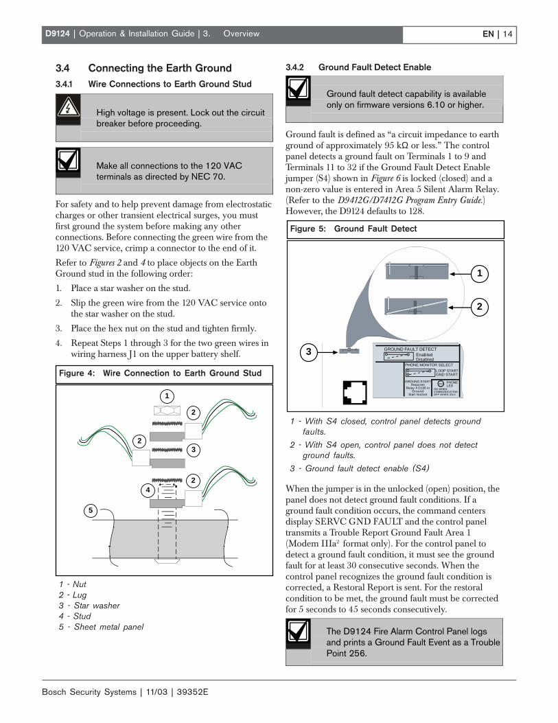
3.4 Connecting the Earth Ground3.4.1 Wire Connections to Earth Ground Stud
High voltage is present. Lock out the circuitbreaker before proceeding.
Make all connections to the 120 VACterminals as directed by NEC 70.
For safety and to help prevent damage from electrostaticcharges or other transient electrical surges, you mustfirst ground the system before making any otherconnections. Before connecting the green wire from the120 VAC service, crimp a connector to the end of it.
Refer to Figures 2 and 4 to place objects on the EarthGround stud in the following order:
1. Place a star washer on the stud.
2. Slip the green wire from the 120 VAC service ontothe star washer on the stud.
3. Place the hex nut on the stud and tighten firmly.
4. Repeat Steps 1 through 3 for the two green wires inwiring harness J1 on the upper battery shelf.
3.4.2 Ground Fault Detect Enable
Ground fault detect capability is availableonly on firmware versions 6.10 or higher.
Ground fault is defined as “a circuit impedance to earthground of approximately 95 kΩ or less.” The controlpanel detects a ground fault on Terminals 1 to 9 andTerminals 11 to 32 if the Ground Fault Detect Enablejumper (S4) shown in Figure 6 is locked (closed) and anon-zero value is entered in Area 5 Silent Alarm Relay.(Refer to the D9412G/D7412G Program Entry Guide.)However, the D9124 defaults to 128.
When the jumper is in the unlocked (open) position, thepanel does not detect ground fault conditions. If aground fault condition occurs, the command centersdisplay SERVC GND FAULT and the control paneltransmits a Trouble Report Ground Fault Area 1(Modem IIIa2 format only). For the control panel todetect a ground fault condition, it must see the groundfault for at least 30 consecutive seconds. When thecontrol panel recognizes the ground fault condition iscorrected, a Restoral Report is sent. For the restoralcondition to be met, the ground fault must be correctedfor 5 seconds to 45 seconds consecutively.
The D9124 Fire Alarm Control Panel logsand prints a Ground Fault Event as a TroublePoint 256.
1 - Nut2 - Lug3 - Star washer4 - Stud5 - Sheet metal panel
Figure 4: Wire Connection to Earth Ground Stud
1
2
32
4
5
2
Figure 5: Ground Fault Detect
1 - With S4 closed, control panel detects groundfaults.
2 - With S4 open, control panel does not detectground faults.
3 - Ground fault detect enable (S4)
GROUND FAULT DETECTEnabledDisabled
PHONELED
RED
ON WHENCOMMUNICATINGOFF WHEN IDLE
LOOP START
PHONE MONITOR SELECT
GROUND STARTRequires
Relay # D136 inGround
Start Socket
GND START
1
3
2

EN | 15D9124 | Operation & Installation Guide |
Bosch Security Systems | 11/03 | 39352E
3.0 Installation
3.5 Installing the D1601 Transformer
Only route AC conduit into the enclosurehousing the D1601 Transformer.
The D1601 is a 120 VAC, 16.5 V/24 VAC dualsecondary transformer. It is the primary power supplyfor the control panel and initiating devices of the D9124System. Install the transformer in the lower left cornerof the D9101 enclosure (see Figure 6).
If the 120 VAC cabling for the transformer isalready installed, make sure the dedicatedcircuit breaker for the system is off and routethe 120 VAC cables away from thetransformer mounting studs.
To install the D1601 Transformer:
1. Remove the hardware taped to the side of thetransformer. Do not leave any part of the plastic bagor tape behind.
2. Place the star washers over the transformer studs inthe lower left corner of the D9101 enclosure (seeFigure 4).
3. Place the transformer over the star washers on thefour transformer mounting studs. Make sure thetransformer cables are routed up as shown in Figure6.
4. Place the washers over the transformer mountingbrackets.
5. Place the nuts over the washers and tighten securelyinto place.
3.6 Connecting the 120 VAC Power InputOnly use a licensed electrician to make 120 VACconnections to the D9124 System. The electrician shouldmake all connections conforming to NEC 70 andconnect the D9124 System to a suitable groundconnection.
To connect the 120 VAC service to the D9124:
1. If the 120 VAC cabling is already installed, go toStep 5. If the 120 VAC cabling is not alreadyinstalled, go to Step 2.
2. Make sure the incoming high voltage (120 VAC)from the D9124 is disconnected.
Turn off the circuit breaker before connectingthe 120 VAC to the system. Leaving thecircuit breaker on can cause injury or deathby electrocution.
3. Remove the knockout cover on the lower left side ofthe D9101 Enclosure and install the appropriatehardware for connection to conduit.
4. Pull the 120 VAC power wires through the conduithardware installed in the knockout, and into thetransformer enclosure.
5. Refer to Section 3.4 Connecting the Earth Ground.Using appropriate hardware, connect wires to theflying leads from connector J1 as shown in Table 4.
6. After the AC power is tied in, install the red metaloxide varistor across the HOT and GND Terminalsof the 110 VAC Power Input of the D9142.
Table 4: High Voltage (120 V) Connections to theD9124 System
Wire From 120 V Service Connect to D9124 System OnGreen Ground stud below D1601White White (on J1)Black Black (on J1)
Figure 6: D1601 Installation

Bosch Security Systems | 11/03 | 39352E
EN | 16D9124 | Operation & Installation Guide | 3. Installation
3.7 Installing Battery Shelves andTransformer Cover
Battery and transformer cables route through notches inthe upper battery shelf and the right side of thetransformer cover. The mounting hardware for thebattery shelf is taped to the shelf. The mountinghardware for the transformer cover is taped to the cover.
To route cables and install the hardware:
1. Insert the connector for wire harness J1 into theupper battery shelf so that the leads hang down fromthe bottom of the shelf.
2. Loosely screw the four screws (provided with eachshelf) into the four shelf mounting holes. See Figure2 for locations.
3. Route the cable connected to the transformer up,and the battery cables down through the notch atthe back of the upper battery shelf. All wireconnections to J1 stay below the battery shelf.
4. Push the upper battery shelf back into place andalign the four holes in the shelf with the screws. Slipthe shelf down over the screws. Do not tighten thescrews yet.
5. Install the bottom battery shelf by loosely drivingthe screws into the mounting flanges, slipping theshelf over the screws, and tightening the screws.
6. Replace the protective cover over the transformerwhile routing the battery cables through the notchon the right side of the transformer enclosure cover.Make sure the shrink wrapped circuit breaker isoutside the notch so it hangs over the lower batteryshelf.
7. Plug the transformer cable into J8 located on thelower left-hand side of the D9142 power supply.
8. Inspect the notch in the battery shelf to verify thetransformer and battery cables route through andhave not slipped outside of the notch as you tightenthe screws on the battery shelf.
9. Verify the covers are securely installed over fuse F1and TB1, and connector P8 is plugged into J8 on theD9142 power supply.
3.8 Mounting the Components3.8.1 D9100 Accessory Module Carrier
The D9100 Accessory Module Carrier includes thefollowing installed modules:
• One D8125 POPEX Module• Two D192C or D192G Indicating Circuit
Supervision Modules• One D928 Dual Phone Line Switcher• One motherboard• One D9142 24 VDC power supply
The D9142 was modified to be compatiblewith the ground fault capability of aD9412GLTB. The modified D9142 unit canbe identified by lot number 0200C or higher.The lot number is located in theupper right-hand corner of the control panel.
The Accessory Module Carrier also includes a D1256Fire Command Center. The right-hand side of thecarrier faceplate has three cutaway sections (see Figure7). The one nearest the D1256 allows you to see theD928 LEDs. The next two provide easy access to thealarm switches on the D192C or D192G Modules.
The wiring harness is assembled at the factory, andterminal blocks only need to be snapped into place inthe designated locations on the D9412GLTB.
Hang the accessory module carrier on the threemounting hinges shown in Figure 2. Then secure thethree screws attached in the bottom three mountingholes.
3.8.2 Control Panel
Hang the control panel on the two mounting hingesshown in Figure 2. Secure the screw attached to the panelin the mounting flange.
3.8.3 Additional Modules
The D9101 enclosure provides four locations formounting additional modules like the D192C or D192GBell Circuit Supervision Module, D125B Powered LoopInterface, D129 Dual Class A Initiating Module, orD8130 Release Modules on D138 mounting brackets.See Figure 2 for mounting locations.
Additional modules affect standby batterycalculations. Due to increased power consumption, youmight need to increase the size of the standby batteriesattached to the D9412GLTB or D9142 power supply. SeeAppendix A: Determining Battery Requirements todetermine the type and number of batteries you need foryour application.
Additional D8125 POPEX Module. If you areinstalling an additional D8125 POPEX Module, installit in the D9100 Accessory Carrier Module (Figure 7) asdescribed in Section 6.2 Connecting the Additional D8125Module.

EN | 17D9124 | Operation & Installation Guide |
Bosch Security Systems | 11/03 | 39352E
1 - D1256 Command Center 6 - D192C/G #12 - Cutaways for D192C/G Modules 7 - D192C/G #23 - Cutaway for D928 8 - D8125 POPEX #1 slot (module installed)4 - D192C/G Indicating Circuit Supervision Modules 9 - D8125 POPEX #2 slot (optional)
5 - D928 Dual Phone Line Switcher 10 - D9142 power supply
Figure 7: Modules Installed on the Accessory Module Carrier
Q
Q
Q
1 2 3 4 5 6 7 8 9 10 11 12 13 14 15 16 17 18 19 20 21 22 23 24 25 26
POPEX 1
D9124 LTB Accessory Module Carrier
Maximum 24VDC output on terminals 5, 7 & 9is 4 Amps.
Maximum 12VDC output on terminal 1 is:
240 mA for single POPEX systems 400 mA for dual POPEX systems.
The D8124G2 system is delivered with asingle D8125 POPEX installed (71points). Itcan be expanded with one additional POPEXfor a total of 134 system points.
POPEX 2
CIRCUIT 1 CIRCUIT 2SILENCE
UP
DOWN
NORMAL
Signaling CircuitDisable Switches
Signaling circuits must beterminated with 560 ý 2 wattEOL resistors, RadionicsPart Number 15-03130-005.
19 20 21 22 23 24 25 2611 12 13 14 15 16 17 18
Q
Q
Q
POPEX 1
D9124 LTB Accessory Module Carrier
Maximum 24 VDC output on terminals 5, 7,and 9 is 4 A.
Maximum 12 VDC output on terminal 1 is: 240 mA for single POPEX systems 400 mA for dual POPEX systems.
The D8124G2 system is delivered with asingle D8125 POPEX installed (71 points). Itcan be expanded with one additional POPEXfor a total of 134 system points.
POPEX 2
CIRCUIT 1 CIRCUIT 2SILENCE
UP
DOWN
NORMAL
Signaling CircuitDisable Switches
Signaling circuits must be terminated with560 Ω 2 W EOL resistors Bosch SecuritySystems (P/N: Number 15-03130-005).
19 20 21 22 23 24 25 2611 12 13 14 15 16 17 18
1 2
3
4
5 6 7
89
10
3.9 Connecting Cables Between D9124System Components
Before you start, review Section 3.3 Safety.
Do not turn AC power on until instructed todo so.
1. Make sure the dedicated AC power source is off. Forinformation about power specifications, refer toSection 7.0 Power Supplies.
2. Connect the four terminal blocks to their locationson the D9412GLTB, making sure each terminalblock clicks firmly into place.
3. Connect the flat ribbon cable between connector J4on the D928 and connector J2 on the D9412GLTB.For more information about the D928, see Section 9.0Telephone Connections.
Do not force the cable in the wrong way. Theends of the flat ribbon cable are keyedso they only plug in one way.
4. If this is a communicating fire system, plug one endof a D161 (20 cm [8 in.]) or D162 (5 cm [2 in.])modular phone cord into J1 on the D928. Plug theother end into the RJ31X (D166) for the primaryphone line and then plug one end of a D161 orD162 phone cord into J2 on the D928. Plug theother end into the RJ31X (D166) for the secondaryphone line.
5. Connect flying lead P1 into J1 (in the upper batteryshelf).
6. Verify transformer cable P8 is connected to J8 onthe lower left side of the D9142 power supply.
3. Installation

Bosch Security Systems | 11/03 | 39352E
EN | 18D9124 | Operation & Installation Guide | 3. Installation
3.10 Wiring Additional ModulesTable 5 shows additional modules you can install withthe D9124 System, and where to connect module cablesto the D9124 System. Connect additional modules(except for D8125 POPEX Modules) to the D9124System as shown in Table 5. Refer to the module’sInstallation Instructions for remote device wiring. Table 5shows only the connections to the D9124 System.
Route cables above the D9100 Accessory ModuleCarrier to locations on the D9412GLTB. Space isprovided at the right side of the accessory modulecarrier to route cables around and below the accessorycarrier to destinations on the motherboard and theD9142 power supply. Use wire ties to bundle multiplecables.
Do not pass cables through the D9100Accessory Module Carrier. The carrier isdesigned to protect enclosed modules fromEMI or other interference that can affectmodule operation. Route all additionalmodule cables around the outside of theAccessory Module Carrier.
3.11 Turning on the PowerBefore turning on the power, lock the Reset Pin (Figure8) on the D9412GLTB. Locking the Reset Pin disablesthe D9124 System. The panel ignores the commandcenters and points while disabled. After power isconnected, CALL FOR SERVICE appears in commandcenter displays while the reset pin is locked down.
1. Lock the Reset Pin on the D9412GLTB (Figure 8).
2. Connect the two sets of batteries. Refer to Installingthe 12 V Standby Source Batteries and Installing the 24V Standby Source Batteries in Section 7.0 PowerSupplies.
3. Turn the AC power on. The batteries begin tocharge, even though the D9412GLTB is stilldisabled. The yellow LED on the D9412GLTBilluminates if the batteries require charging.
Figure 8: Reset Pin
1 - Reset pin locked (closed)2 - Reset pin normal (open)
PERIPHERAL DEVICE CONNECTIONS
Operation MonitorPulses When Normal
Flickers When RingingSolid When Held In Reset
RED
YELLOW
GREEN
BLACK
32POWER +
DAT BUS A
DATA BUS B
COMMON
31
30
29
Reset PinDisable All Except Battery
Charging And Local Programming
GRN
1
2
Table 5: Wiring Additional Modules
D9124 Terminals D125BTerminal
D127Terminal
D129Terminal
D192C/GTerminal
D8129Terminal
D8130Terminal
Motherboard TB1 1 (12 VDC) - 8 6 AUX AUX 3Motherboard TB1 2 (COM) 4 and 10 1 and 3 8 COM GND 1Motherboard TB1 3 (Data Out) - - - - - -Motherboard TB1 4 (Data In) - - - - - -Motherboard TB1 5 (Switched 24 VDC) 1 - - - - -Motherboard TB1 6 (COM) 5 - 7 - - -
D9412GLTB TB2/3 Points 1 to 6 2 and/or 3 - 5 and/or 9 SUPV ZONE - 4D9412GLTB TB1 6 (Alarm Output) - 9 or 10 - ALARM TRIG - 2
D9412GLTB ZONEX OUT - - -- ZN1 OUT or
ZN2 OUT
EN | 19D9124 | Operation & Installation Guide |
Bosch Security Systems | 11/03 | 39352E
4. Command Centers andAnnunciation Devices
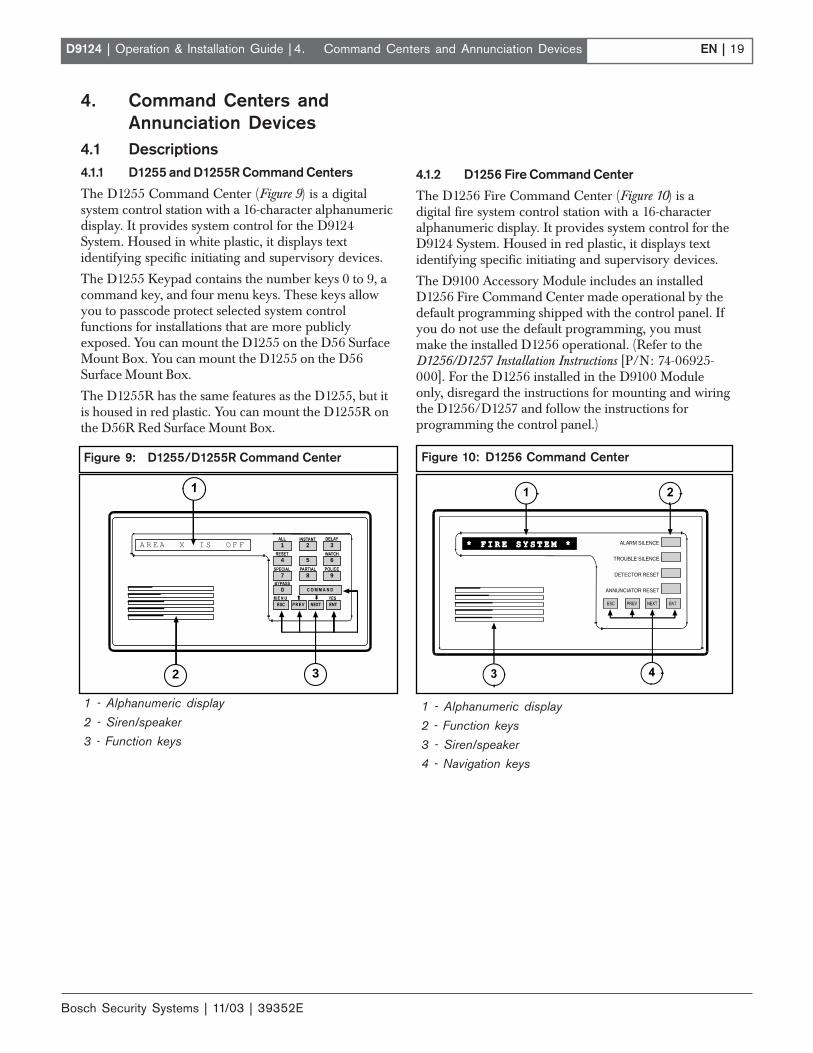
4.1 Descriptions4.1.1 D1255 and D1255R Command Centers
The D1255 Command Center (Figure 9) is a digitalsystem control station with a 16-character alphanumericdisplay. It provides system control for the D9124System. Housed in white plastic, it displays textidentifying specific initiating and supervisory devices.
The D1255 Keypad contains the number keys 0 to 9, acommand key, and four menu keys. These keys allowyou to passcode protect selected system controlfunctions for installations that are more publiclyexposed. You can mount the D1255 on the D56 SurfaceMount Box. You can mount the D1255 on the D56Surface Mount Box.
The D1255R has the same features as the D1255, but itis housed in red plastic. You can mount the D1255R onthe D56R Red Surface Mount Box.
4. Command Centers and Annunciation Devices
1 - Alphanumeric display
2 - Siren/speaker3 - Function keys
Figure 9: D1255/D1255R Command Center
0
8 9
32
5 6
7
4
A R E A X I S O F F 1
32
4.1.2 D1256 Fire Command Center
The D1256 Fire Command Center (Figure 10) is adigital fire system control station with a 16-characteralphanumeric display. It provides system control for theD9124 System. Housed in red plastic, it displays textidentifying specific initiating and supervisory devices.
The D9100 Accessory Module includes an installedD1256 Fire Command Center made operational by thedefault programming shipped with the control panel. Ifyou do not use the default programming, you mustmake the installed D1256 operational. (Refer to theD1256/D1257 Installation Instructions [P/N: 74-06925-000]. For the D1256 installed in the D9100 Moduleonly, disregard the instructions for mounting and wiringthe D1256/D1257 and follow the instructions forprogramming the control panel.)
1 - Alphanumeric display
2 - Function keys3 - Siren/speaker4 - Navigation keys
Figure 10: D1256 Command Center
ALARM SILENCE
TROUBLE SILENCE
DETECTOR RESET
ANNUNCIATOR RESET
Radionics
Bosch Security Systems | 11/03 | 39352E
EN | 20D9124 | Operation & Installation Guide |
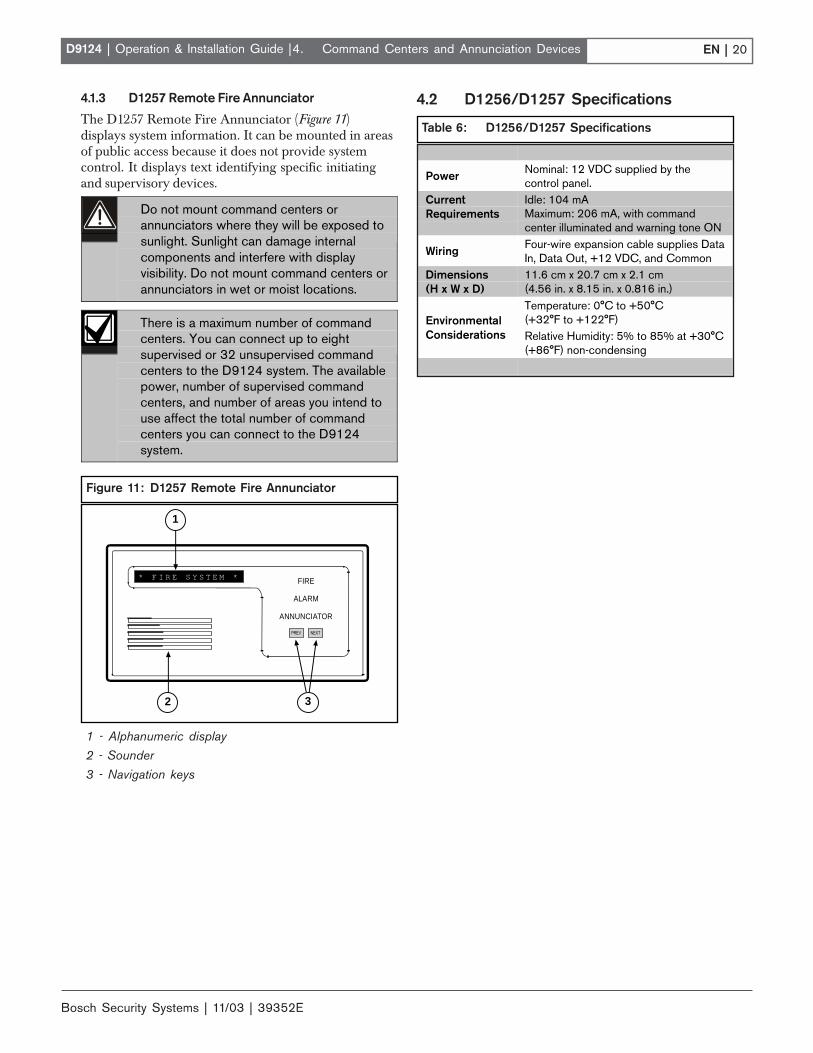
4.1.3 D1257 Remote Fire Annunciator
The D1257 Remote Fire Annunciator (Figure 11)displays system information. It can be mounted in areasof public access because it does not provide systemcontrol. It displays text identifying specific initiatingand supervisory devices.
Do not mount command centers orannunciators where they will be exposed tosunlight. Sunlight can damage internalcomponents and interfere with displayvisibility. Do not mount command centers orannunciators in wet or moist locations.
There is a maximum number of commandcenters. You can connect up to eightsupervised or 32 unsupervised commandcenters to the D9124 system. The availablepower, number of supervised commandcenters, and number of areas you intend touse affect the total number of commandcenters you can connect to the D9124system.
4. Command Centers and Annunciation Devices
1 - Alphanumeric display2 - Sounder3 - Navigation keys
Figure 11: D1257 Remote Fire Annunciator
FIRE
ALARM
ANNUNCIATOR
* F I R E S Y S T E M *
Radionics
32
1
Table 6: D1256/D1257 Specifications
Power Nominal: 12 VDC supplied by thecontrol panel.
CurrentRequirements
Idle: 104 mAMaximum: 206 mA, with commandcenter illuminated and warning tone ON
Wiring Four-wire expansion cable supplies DataIn, Data Out, +12 VDC, and Common
Dimensions(H x W x D)
11.6 cm x 20.7 cm x 2.1 cm(4.56 in. x 8.15 in. x 0.816 in.)Temperature: 0°C to +50°C(+32°F to +122°F)Environmental
Considerations Relative Humidity: 5% to 85% at +30°C(+86°F) non-condensing
4.2 D1256/D1257 Specifications

EN | 21D9124 | Operation & Installation Guide |
Bosch Security Systems | 11/03 | 39352E
4. Command Centers and Annunciation Devices
4.3 Installing Command Centers andAnnunicators
A four-wire flying lead is required for the data andpower connections between the D1255, D1255R, D1256,and motherboard. They come with a wiring assemblyconsisting of four color-coded flying leads and a female,four-pin connector plug at one end.
1. Using a small, flat-bladed screwdriver, gently push inthe two bottom tabs of the command centerenclosure cover. As you push back the tabs, lift thecommand center cover away from the base.
2. Set the address settings as shown in Table 7. Forsupervised command centers, assign only one toeach address.
3. Turn the command center over and plug in thewiring connector through the opening in the back ofthe enclosure base.
4. Mount the command center base in the desiredlocation and secure it using the mounting holesinside the enclosure base.
5. Replace the cover. Align and insert the top two tabsof the enclosure cover into the top two tab slots ofthe enclosure base. Hold the top edges of theenclosure cover and base in position. Push the tabsinward and press the enclosure and cover togetheruntil the cover snaps into place.
6. Press each key on the keypad toward the top of thecommand center to ensure proper alignment andoperation of each key through the mating keypadfaceplate openings.
7. Install the locked cover according to the instructionsprovided.
The remote command centers have lockablecovers. Protect remote command centerswith a locked cover such as the SafetyTechnology’s 6550 Wide Body KeypadProtector.
8. Connect the flying leads of the wiring assembly(provided) to the wires from the panel (see Table 8).
Table 7: Command Center Address Settings
AddressSwitch
1 2 3 4 5 6 7 81 ON OFF ON OFF ON OFF ON OFF2 ON ON OFF OFF ON ON OFF OFF3 ON ON ON ON OFF OFF OFF OFF4 Leave ON – Do not use5 Encoding Tone ON/OFF6 Leave ON – Factory Test
Switching the green and yellow wires affectsother command centers.
Incorrectly connecting the green wire fromthe command center to the motherboardTerminal 4 and the yellow wire to Terminal 3,causes other command centers connectedto the control panel to go blank and/orsound random tones.
You can connect a maximum of 4.6 km (15,000 ft.) of22 AWG (0.8 mm) wire for all command centers andprinter modules combined to the data bus, Terminal3, and Terminal 4 on the motherboard. You can connectparallel wire runs from the D9124 System to eachdevice, run wire device to device, or combine the two.However, limit the individual wire runs to commandcenters to 0.61 km (2000 ft.).
Extra power is needed for more commandcenters and annunciators. The D1255,D1255R, D1256, and D1257 each draw104 mA when idle. Each draws 206 mA withthe back lighting for the keys illuminated andthe sounder activated. Review Section 7.0Power Supplies and Appendix A.1 AuxiliaryCurrent and Standby Battery Requirementsto determine the total power outputrequirements for your system.
You might need to add one or more UL Listed powersupplies for the number of command centers you wantto use.
D9124 and the additional power suppliesmust share COMMON.
When using an additional power supply topower command centers, the common fromthe additional power supply must connect toboth command centers' common and thecommon on the D9412GLTB board.A stand-alone power supply powering anydevice connected to the D9124 must alsobe connected to a common terminal on theD9124.
Wire Color Motherboard TerminalRed 1 +12 VDCBlack 2 CommonYellow 3 Serial Data OutGreen 4 Serial Data In
Table 8: Command Center Connections

Bosch Security Systems | 11/03 | 39352E
EN | 22D9124 | Operation & Installation Guide |
Notes:
4. Command Centers and Annunciation Devices

EN | 23D9124 | Operation & Installation Guide |
Bosch Security Systems | 11/03 | 39352E
5. Indicating Circuit (24 VDCHorns/Strobes/Bells)
5.1 DescriptionThe D192C or D192G Indicating Circuit Modulesupervises the wiring from the control panel to remotealarm indicating devices like horns, strobes, and bells.Wiring is supervised for open, shorted, or groundedcircuit faults.
Signaling devices must:
• be polarized (DC).
• match the voltage rating of the alarm power supply(D9142).
• not exceed the current rating of the alarm powersupply (D9142).
• not exceed 1.8 A on motherboard Terminals 7 or 9when combined.
Total output power for the D9124 systemmust not exceed 4 A. The total output powerfor auxiliary power (Terminal 5) and 24 VDCindicating circuits (Terminals 7 and 9) mustnot exceed 4 A. Exceeding 4 A overloads theD9142 power supply. See A.1.2Calculations for 24 VDC Devices todetermine total output requirements.
5.2 OperationDuring normal operation, the indicating circuit issupervised for incorrectly installed devices, opens,shorts, and grounds. If any of these conditions aredetected, the control panel indicates a Trouble conditionat the command center. You can program the controlpanel to report the condition to the central station.
When the control panel detects an alarm, the alarmoutput circuit triggers the D192C or D192G to supplycircuit power from the power supply.
To provide supervision, install the 560 Ω, 2 W EOLresistor (P/N: 15-03130-005) beyond the last indicatingdevice. Two resistors are supplied in the literaturepackage.
5. Indicating Circuit (24 VDC Horns/Strobes/Bells)
5.3 Silence SwitchThe D192C or D192G has a toggle switch to disable thefire alarm indicating devices while you test the controlpanel (Figure 12). When this switch is toggled up in theSILENCE position, the D192C or D192G presents ashort circuit to Point 7, causing a Trouble response.
Figure 12: D192/D192G Bell Silence Switch

Bosch Security Systems | 11/03 | 39352E
EN | 24D9124 | Operation & Installation Guide |
Notes:
5. Indicating Circuit (24 VDC Horns/Strobes/Bells)

EN | 25D9124 | Operation & Installation Guide |
Bosch Security Systems | 11/03 | 39352E
6. ZONEX, Addressable Points6.1 DescriptionYou can use POPIT Modules to provide up to 238off-board points, bringing the total number of points theD9124 System can monitor to 246. Each off-board pointrequires a POPIT Module.
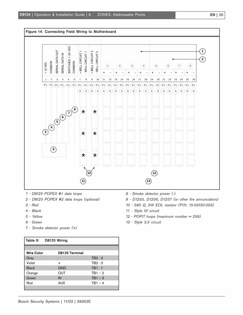
POPITs connect to supervised two-wire data expansionloops run from POPIT to POPIT throughout thepremises (Figure 14). Data expansion loops connect tothe motherboard. The motherboard connects to thePOPEX Module. POPEX Modules connect to the pointbus on the control panel.
You can connect up to four data expansion loops to oneD8125 input at the motherboard. Data Loops 1 to 4connect to the D8125 POPEX 1 input on themotherboard (Terminals 11 through 18). Data Loops 5 to8 connect to the D8125 POPEX 2 input at themotherboard (Terminals 19 through 26).
If a POPIT is disconnected from the expansion loop, atrouble message appears immediately. See the D9412G/D7412G Program Entry Guide for programming options.
Placing a short on the data expansion loop generates aPT Bus Trouble Report. The control panel sees all pointson the shorted expansion loop as shorted and respondsaccording to point programming. The fire pointsrespond locally as a Trouble condition and transmitMissing Fire Reports if programmed during thiscondition.
POPIT Modules monitor their sensor loops for threeconditions: Loop Normal, Loop Open, and LoopShorted. They report these three conditions to thecontrol panel.
The D9124 uses point programming to interpret thesensor loop information reported by the POPITs andmakes the appropriate system response. Initiationdevices connect to each POPIT. The POPIT sensorloop can supervise an unlimited number of initiationdevices. Certain applications can limit the number ofinitiation devices. Consult the appropriate NFPAstandards.
The POPIT comes in a tampered enclosure (D9127T) oran untampered enclosure (D9127U).
Verify the proper setting of motherboard jumpers:Make sure the jumpers above Terminals 18 to 24 on themotherboard are in the D8125 position (Figure 13).
6.1.1 POPEX/POPIT Configurations
With the D8125 POPEX Module, you can:
• use D8125 POPEX 1, data loops 1 to 4 (Terminals11 to 18) on the motherboard (Figure 14).
• install a maximum of 119 POPITs (Points 9 to 127).
• use Points 7 and 8 for power supply and initiationcircuit supervision. POPITs are not required forthese functions.
With an additional D8125 POPEX Module, you can:
• use D8125 POPEX 2, data loops 5 to 8 (Terminals19 to 26) on the motherboard (see Figure 14).
• install an additional 119 POPITs (Points 129 to 247)for a maximum of 238 POPITs in the system.
6.2 Connecting the Additional D8125Module
1. Mount the module to a D138 mounting bracket,using only the three screws provided.
2. Mount this assembly in the empty slot next to theother modules on the Accessory Module Carrier.Use the orientation of the other modules as a guide.See Figure 2.
3. Connect the clip-on end of the extra wiring harnessto the far right connector ( J5) on the motherboard.
4. Connect the hanging wires to the D8125 Module asshown in Table 9.
6. ZONEX, Addressable Points
Figure 13: D8125 Jumper Setting
1 - Jumpers set in the D8125 position.
J9
17 18 19 20 21 22 23 24 25 26
J9 J8 J7 J 1 2 J11 J 1 0
P5
1
Bosch Security Systems | 11/03 | 39352E
EN | 26D9124 | Operation & Installation Guide | 6. ZONEX, Addressable Points
Table 9: D8125 Wiring
Wire Color D8125 TerminalGray - TB2 - 2Violet + TB2 - 3Black GND TB1 - 1Orange OUT TB1 – 2Green IN TB1 – 3Red AUX TB1 – 4
Figure 14: Connecting Field Wiring to Motherboard
S S S S
P L P L P L P L P L P L P L P L P L P L P L P L P L P L P L P L P L P L P L P L P L P L P L P L
S S S S S S S S SS S SS S S S
+ - + - + - + - + - + - + - + -
8654321 7
* *
* *
* *
P LP L
1 2 3 4 5 6 7 8 9 10 11 12 13 14 15 16 17 18 19 20 21 22 23 24 25 26
1
2
34
56
87
9
11
10
13
12
1 - D8125 POPEX #1 data loops 8 - Smoke detector power (-)2 - D8125 POPEX #2 data loops (optional) 9 - D1255, D1256, D1257 (or other fire annunciators)3 - Red 10 - 560 Ω, 2W EOL resistor (P/N: 15-03130-005)4 - Black 11 - Style W circuit
5 - Yellow 12 - POPIT loops (maximum number = 238)6 - Green 13 - Style 3.5 circuit7 - Smoke detector power (+)

EN | 27D9124 | Operation & Installation Guide |
Bosch Security Systems | 11/03 | 39352E
6.3 Selecting POPIT Point AssignmentsOff-board points are numbered 9 to 127 and 129 to 247.
The D9124 System reserves points 128 to248 for internal use to supervise the dataloops.
You must connect POPITs for points 129 to 247 to theexpansion loops connected to D8125 POPEX #2.
Addresses for each POPIT assign the module to a pointnumber. POPIT address settings are in Section 6.3.1POPIT Labels and the Point Assignments section of theD9124 Program Record Sheet (Figure 15).
6.3.1 POPIT Labels
Four sheets of peel-off POPIT labels are supplied withthe D9124 System. Use the sheet marked Vertical Grid forD8125 POPEX #1 for points 9 to 127. Use the sheetmarked Vertical Grid for D8125 POPEX #2 for points 129to 247.
Each label has two parts. Place the smaller part(containing only the point number) on the POPITterminal block. Place the larger part (containing addresssettings) on the POPIT cover. Set the addresses andcover the POPIT.
Do not program two POPITs for the same point number.After you program all the points, perform a Fire Test orService Walk Test. See Section 11.0 Testing the System forinstructions. If a point does not test properly, check theprogramming for a duplicated address.
6. ZONEX, Addressable Points
6.3.2 Program Record Sheet
Column One: Contains the address settings for thePOPITs. Addresses are numbered 0 to 6, left to right.Set addresses whose number appears in the ON position.Set addresses with a dash (-) in the OFF position (Figure15).
Column Two: Contains the translation of the pointnumber into the D8112 ZONEX format. See Point/UserFlag in the 9000MAIN Module of the D9412G/D7412GProgram Entry Guide for an explanation of this feature.
Column Three: Contains the point number as itappears at the command centers.
Column Four: Contains the point index. See the PointIndex Module in the D9412G/D7412G Program EntryGuide for an explanation of the point index.
Column Five: Shows the area to which the point isassigned.
Column Six: Shows the Debounce Count for the point.See P### Debounce in the Point Assignments Module ofthe D9412G/D7412G Program Entry Guide.
Column Seven: Shows the BFSK report code, thepoint number reported for this point when the controlpanel is using the BFSK format.
Column Eight: Contains the text displayed atcommand centers for the point. The text is transmittedto the receiver when the control panel is using theModem IIIa2 format.
Figure 15: Program Record Sheet
D9412G/D7412G | Program Record Sheet | RADXPNTS Handler EN | 24
RADXPNTS Handler Default values are shown in ( ) or in bold
Point Assignments (001 through 040)POPIT Switch
SettingTrans-lation
Point#
PointIndex
AreaAssign
DebounceBFSK/Relay
Custom Point Text
100 001 (3) _ _ (1) ___ (2) _____ (1) ____ P1 FIRE ___________________
200 002 (1) _ _ (1) ___ (2) _____ (2) ____ P2 PANIC ___________________
300 003 (25) _ _ (1) ___ (2) _____ (3) ____ P3 DELAY ___________________
400 004 (13) _ _ (1) ___ (2) _____ (4) ____ P4 FOLLOW ___________________
500 005 (7) _ _ (1) ___ (2) _____ (5) ____ P5 INSTANT ___________________
600 006 (7) _ _ (1) ___ (2) _____ (6) ____ P6 INSTANT ___________________
700 007 (7) _ _ (1) ___ (2) _____ (7) ____ P7 INSTANT ___________________
800 008 (7) _ _ (1) ___ (2) _____ (8) ____ P8 INSTANT ___________________

Bosch Security Systems | 11/03 | 39352E
EN | 28D9124 | Operation & Installation Guide | 6. ZONEX, Addressable Points
6.4 Installing POPITsEach POPIT comes with an installation card. Youshould be familiar with the POPIT installation cardbefore attempting to install POPITS.
6.4.1 Routing the Data Cable
The two-wire data expansion loop connects POPITModules assigned to a single D8125 POPEX. You canconnect up to four data loops to one D8125 at themotherboard. Data Loops 1 to 4 connect to D8125POPEX #1. Data Loops 5 to 8 connect to D8125POPEX #2 (Figure 14).
Total resistance of the D8125 POPEX DataLoops cannot exceed 60 Ω regardless ofwire gauge or distance used. To estimateresistance, refer to Table 10.
To determine total resistance, tie the ends of the D8125POPEX Data Loops together to eliminate POPITresistance (Figure 16). After measuring resistance, untiethe ends of the D8125 POPEX Data Loops.
Electromagnetic interference (EMI) maycause problems. If you suspect EMI isa problem, refer to Section 12.9 EMI onLong Wire Runs.
Figure 16: Checking Resistance of Data Loops
1 - POPIT 3 - 60 Ω maximum2 - Ohmmeter 4 - Short ends together (testing only)
Ω
1
23
4
Table 10: Resistance by Wire Size
Wire SizeAWG mm
Ω per 305 m (1000 ft.)
12 2.3 1.6214 1.8 2.5816 1.5 4.0918 1.2 6.5120 1.0 10.4022 0.8 16.50
6.4.2 Connect POPITS to the Data Cable
You do not need to wire POPIT Modules in any orderon the motherboard D8125 POPEX Data ExpansionLoop. An address setting on each POPIT (Section 6.3Selecting POPIT Point Assignments) identifies the point ofprotection, regardless of its physical location on the datacable. POPIT Modules must be mounted at least 7.6 cm(3 in.) apart and using at least 15.2 cm (6 in.) of wire.This prevents the tamper magnets from interfering witheach other.
Connect POPIT Modules to the data loop in parallel.Do not T-tap POPIT Data Loops together (Figure 17).
1. Connect the positive (+) data terminal from onePOPIT to the positive (+) data terminal on the nextPOPIT.
2. Connect the negative (-) data terminal from onePOPIT to the negative (-) data terminal on the nextPOPIT.
3. Repeat Steps 1 and 2 to connect all POPITs on thesame D8125 POPEX Data Loop.
6.4.3 Connecting the D291S and D291MAddressable Smoke Detector Bases
To prevent damage to the POPEX module,wire smoke detector bases when the datacable is disconnected from the motherboard.Before connecting detector wiring to thecontrol panel, meter each wire to ground tocheck for continuity, and meter betweeneach wire for continuity. You should have nogrounds or shorts between any of the wires.Put the detector heads on after you havemetered all the wiring (Figure 18).
Before beginning the installation, refer to theOperation and Installation Guides for thesedetectors.
6.5 Connecting Data Loops to Terminalson the Motherboard
D8125 POPEX modules must have theirown data expansion loops. The motherboardprovides two sets of D8125 POPEX DataLoops. POPIT modules assigned to D8125POPEX #1 cannot be placed on the D8125POPEX #2 Data Loop. Limit the data loopsreturning to the motherboard to a maximumof four data loop runs for each POPEX youinstall. See Table 11.

EN | 29D9124 | Operation & Installation Guide |
Bosch Security Systems | 11/03 | 39352E
6. ZONEX Addressable Points
Table 11: Data Loops and POPITs
D8125 POPEX #1 D8125 POPEX #2Data Loops 1 to 4 Data Loops 5 to 8Points 9 to 127 Points 129 to 247
1 - D9127U/T 4 - POPIT switch block (typically up to 119 places)2 - POPIT sensor loop (typically up to 119 places) 5 - To motherboard D8125 POPEX data loop3 - 33 kΩ EOL resistor (typically up to 119 places) 6 - Up to 119 POPITs
Figure 17: Connecting POPITs to Data Cable
5
(-)(+)
1 1 1
6
(–)(+)
2 3 2 3 32
444
6.6 Wiring the POPIT Sensor LoopPOPIT Modules monitor their sensor loops for threeconditions: Loop Normal, Loop Open, and LoopShorted. They report these three conditions to theD9124 System.
The D9124 System uses point programming to interpretthe sensor loop information reported by the POPITsand make the appropriate system response.
Terminate all POPIT sensor loops with a 33 kΩ EOLresistor, Bosch Security Systems Model D106F, suppliedwith each POPIT Module. See Figures 19 and 20.
6.6.1 POPIT DisplaysFor a list of D1255, D1256, and D1257 displays, refer tothe User’s Guide provided with the command center orfire alarm annunciator.
Figure 18: Connecting Devices to the Motherboard
+-
+-
+-
+-
+-
+-
+-
+-
12
3
4
5
6
7
7
66
1
1 - Motherboard 3 - Common 5 - Data loop negative 7 - To next2 - Switched + 24 VDC 4 - Data loop positive 6 - D291M/D291S base
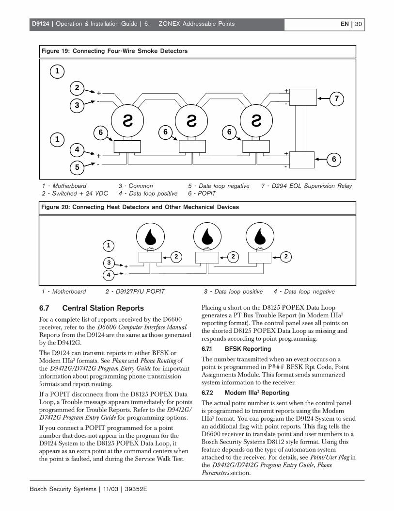
Bosch Security Systems | 11/03 | 39352E
EN | 30D9124 | Operation & Installation Guide | 6. ZONEX Addressable Points
1 - Motherboard 2 - D9127P/U POPIT 3 - Data loop positive 4 - Data loop negative
Figure 20: Connecting Heat Detectors and Other Mechanical Devices
+-
1
2 2 23
4
6.7 Central Station ReportsFor a complete list of reports received by the D6600receiver, refer to the D6600 Computer Interface Manual.Reports from the D9124 are the same as those generatedby the D9412G.
The D9124 can transmit reports in either BFSK orModem IIIa2 formats. See Phone and Phone Routing ofthe D9412G/D7412G Program Entry Guide for importantinformation about programming phone transmissionformats and report routing.
If a POPIT disconnects from the D8125 POPEX DataLoop, a Trouble message appears immediately for pointsprogrammed for Trouble Reports. Refer to the D9412G/D7412G Program Entry Guide for programming options.
If you connect a POPIT programmed for a pointnumber that does not appear in the program for theD9124 System to the D8125 POPEX Data Loop, itappears as an extra point at the command centers whenthe point is faulted, and during the Service Walk Test.
Placing a short on the D8125 POPEX Data Loopgenerates a PT Bus Trouble Report (in Modem IIIa2
reporting format). The control panel sees all points onthe shorted D8125 POPEX Data Loop as missing andresponds according to point programming.
6.7.1 BFSK Reporting
The number transmitted when an event occurs on apoint is programmed in P### BFSK Rpt Code, PointAssignments Module. This format sends summarizedsystem information to the receiver.
6.7.2 Modem IIIa2 Reporting
The actual point number is sent when the control panelis programmed to transmit reports using the ModemIIIa2 format. You can program the D9124 System to sendan additional flag with point reports. This flag tells theD6600 receiver to translate point and user numbers to aBosch Security Systems D8112 style format. Using thisfeature depends on the type of automation systemattached to the receiver. For details, see Point/User Flag inthe D9412G/D7412G Program Entry Guide, PhoneParameters section.
Figure 19: Connecting Four-Wire Smoke Detectors
+
-
+
-
+-
+-
1
1
2
3
4
5
6 6 6
7
6
1 - Motherboard 3 - Common 5 - Data loop negative 7 - D294 EOL Supervision Relay2 - Switched + 24 VDC 4 - Data loop positive 6 - POPIT

EN | 31D9124 | Operation & Installation Guide |
Bosch Security Systems | 11/03 | 39352E
7. Power Supplies7.1 D9412GLTB, Command Center, and
Modules7.1.1 Primary Power
Primary (AC) Power Circuit
A 16.5 VAC/24 VAC dual secondary transformer (BoschSecurity Systems Model D1601) is the primary powersource. The AC power circuit provides 1.9 A of rectifiedAC power. The control panel reserves 500 mA of thispower for internal operations, leaving 1.4 A for powereddevices.
Transient suppressors and spark gaps protect the circuitfrom power surges. This protection relies on the groundconnection at Terminal 10. Make sure Terminal 10 isconnected to a proper ground. See Section 3.4 Connectingthe Earth Ground.
AC Power Failure
The system indicates an AC power failure when thepower at Terminals 1 and 2 is missing. The AC FailTime program item sets the number of minutes ACmust be missing before the control panel acknowledgesthe failure and the number of minutes after the powerreturns before the control panel acknowledges therestoral of power.
You can program AC Fail Time from 1 second to 90minutes. The Bosch Security Systems default sets ACFail Time at 82 seconds.
7.1.2 Secondary Power
Two 12 V, 7 Ah (up to 14 Ah) sealed lead-acidrechargeable batteries (D126) or two 12 V, 17.2 or 18 Ah(up to 34.4 or 36 Ah) sealed lead-acid rechargeablebatteries (D1218) supply secondary power for the controlpanel, the command centers, auxiliary and alarmoutputs, and powers the system during interruptions inprimary (AC) power.
When connecting two D1218 Batteries tothe control panel, both must have the samecapacity (use two 17.2 Ah batteries or two18 Ah batteries).
In applications where the supervision of two batteries isrequired, you must use a D113 Battery SupervisionModule.
Only use lead-acid batteries. The chargingcircuit is calibrated for lead-acid batteries.Do not use gel-cell or nicad batteries.
Choosing the Right Batteries to Meet 12 VRequirements
To determine the correct battery size connecting to thesystem, you must know the amount of current the 12 Vdevices draw from the D9412GLTB. You also must knownumber of hours the batteries are expected to last. Referto 12 VDC Device Calculations in Appendix A: DeterminingBattery Requirements for worksheets of the actualcalculations that must be performed to determine thecurrent draw for your installation and the UL andNFPA standby battery requirements for yourapplication.
Dual batteries are required for fire applications.
Table 12 contains examples of the impact of adding 12 Vdevices while meeting UL and NFPA requirements forfire detection systems.
Table 12 is for illustrative purposes only. Youmust perform actual calculations todetermine the requirements for yourinstallation and application.
7. Power Supplies
Table 12: Examples of Standby Power Requirements (12 V Devices)
Battery or Power Supply RequirementsSystem Includes Column BTotal (mA)
Column CTotal (mA) 24-Hour Standby 60-Hour Standby
D9124 only 562 874 One D1218Additional power supply andbatteries
D9124 + command center 668 1080 Two D1218sAdditional power supply andbatteries
D9124 + command center +119 POPITs
1025 1556 Two D1218sAdditional power supply andbatteries
D9124 + D8125 + 238POPITs + command center
1430 2080Additional power supply andbatteries
Additional power supply andbatteries
Bosch Security Systems | 11/03 | 39352E
EN | 32D9124 | Operation & Installation Guide |
Installing the 12 V Standby Source Batteries
When connecting two batteries, connect them inparallel. Before handling the batteries, see Section 3.1Safety for important information.
1. Place the batteries on the bottom shelf. The longerset of leads from the battery harness connects to thebattery on the right side of the battery shelf.
2. Connect the black negative wires from the batteryharness to the negative terminals on the batteries.
3. Connect the red wires from the battery harness tothe positive terminals on the batteries.
High-current arcs are possible. The positive(red) battery lead and Terminal 5 can createhigh-current arcs if shorted to other terminalsor the enclosure. Use caution when workingwith the positive lead and Terminal 5. Alwaysdisconnect the positive (red) lead from thebattery before removing it from Terminal 5.
Adding Additional Power Supply and Batteries
D8132 boosts battery backup. Adding aD8132 Battery Charger Module supportsadditional batteries of up to 36 Ah capacity,if required.
In applications where the supervision of twobatteries is required, you must use a D113Battery Supervision Module.
Use the D8132 Battery Charger Module to connect twoadditional batteries for a total of four. The control panelplus any connected D8132 Modules and AUX powersupplies must be on the same AC circuit for dischargingevenly if AC power fails. The number of D8132Modules is determined by the number of availableoutlets on the same circuit. See Table 15 for batterystandby time calculations.
Replacing the Battery
Replace batteries every 3 to 5 years under normal use.Exceeding the maximum output ratings causes heavydischarges. Routine heavy discharges can lead topremature battery failure. Record the date of installationdirectly on the battery.
Battery Supervision
When battery voltage drops to 13.8 VDC, the yellowCharging Status LED lights. When the battery drops to12.1 VDC, the red Low Battery LED lights and thecontrol panel, if programmed for power supervision,transmits a Battery Low Report in the Radionics’Modem IIIa2 Communication Format. It transmits aTrouble ZN 9 Report in the BFSK format.
If the battery is missing or shorted, the red Low BatteryLED flashes at the same rate as the green OperationMonitor LED. If the control panel is programmed forpower supervision, it transmits a Battery Missing Reportin the Modem IIIa2 format, or Trouble ZN 9 Report inthe BFSK format.
When battery voltage returns to 13.7 VDC, the LowBattery LED goes out. If the control panel isprogrammed for power supervision, it transmits aBattery Restoral Report in the Radionics’ Modem IIIa2
Communication Format or Restoral ZN 9 Report in theBFSK format. At 13.9 VDC, the Charging Status LEDgoes out.
Investigate low battery reports immediately. Ifprimary (AC) power is off and the dischargecontinues, the control panel becomesinoperative when the battery voltage dropsbelow 10.2 VDC.
Battery Charging Circuit
The float voltage for the battery charging circuit is13.5 VDC to 13.9 VDC at a maximum current of 1.4 A.If float voltage drops below 13.5 VDC, the ChargerLED illuminates.
Loss of AC Load Shed Relay protectsbatteries. During an AC power loss, thebatteries supply all power to the D9124control panel. If the battery voltage fallsbelow 10.2 V during an AC power loss, aload shed relay isolates the battery from thecontrol panel and disables the control panel.Load shed protects the battery from beingdamaged by deep discharge. When ACpower restores, the load shed relay resetsand battery voltage is again available.
Overcharge load shed with AC present. Ifmore than 1.4 A of current draw from thecontrol panel is detected, the control panelshuts down. Remove all loads to the controlpanel and disconnect AC power. Add a newbattery and reconnect AC power.
Reset the control panel by momentarily placing theReset pin in the disable position (Figure 8). The red LowBattery LED continues flashing until you reset thecontrol panel.
A shorted battery condition is created by a shorted cellinside the battery or by a short on Terminals 4 and 5. Ashorted battery may generate Watchdog Reset Reports.
See Table13 for the battery discharging and rechargingcycles. Table 14 identifies and defines the ChargingStatus and Low Battery LEDs.
7. Power Supplies

EN | 33D9124 | Operation & Installation Guide |
Bosch Security Systems | 11/03 | 39352E
7. Power Supplies
Table 13: Battery Discharge and Recharge Cycles
Discharge Cycle Recharge CycleFloat Voltage (VDC) Indication Float Voltage (VDC) Indication13.9 • Battery is fully charged.
• Charging Status LED is off.AC is on. • Load Shed relay resets.
• Battery charging begins.• Battery Trouble and AC Restoral
Reports sent.13.8 • Charging Status LED is on. 13.7 • Battery Restoral Report sent.
• Low Battery LED is off.12.1 • Battery Trouble and AC Fail
Reports, if programmed.• Low Battery LED is on.
13.9 • Charging Status LED is off.• Battery is fully charged.
10.2 • Battery Load Shed(processing continues if ACpresent.)
Table 14: Charging Status and Low Battery LEDs
Type LED Color LED State IndicatesYellow Shows the charging status of the battery.Yellow Off Battery is fully charged.
If the battery is missing, shorted, or reversed, the Charging Status LED isoff. The red Low Battery LED is flashing.
ChargingStatusLED
Yellow On Battery float charge is below 13.8 VDC. If AC is present, the battery ischarging.Combined current draw from all outputs exceeds 1.4 A (normal underalarm conditions for non-fire systems when sirens of bells draw more than1.4 A).If the LED illuminates regularly for extended periods or does not go out,check the current draw for devices connected to the power outputs. SeeSection 8.0 Power Outputs for instructions.
Red Shows the battery condition.Red Off Battery is fully charged.Red On Battery voltage is below 12.1 VDC. LED goes off when voltage reaches
13.7 VDC.
LowBatteryLED
Red Flashes (same rateas Green LED)
Battery is missing or shorted. (Green LED is the Operation Monitor LED.)

Bosch Security Systems | 11/03 | 39352E
EN | 34D9124 | Operation & Installation Guide | 7. Power Supplies
7.2 24 VDC Initiating and IndicatingDevices
7.2.1 Primary Power
The D1601 is a 120 VAC, 16.5 V/24 VAC dualsecondary transformer, which is the primary powersupply for the control panel and initiating devices of theD9124. See Section 3.5 Installing the D1601 Transformerfor more information about installing the D1601.
7.2.2 Secondary Power
Secondary power for the alarm indicating devices (suchas bells, horns, and strobes) is supplied by two D12612 V, 7 Ah sealed lead-acid rechargeable batteries or upto two external D1218 12 V, 17.2 or 18 Ah sealed lead-acid rechargeable batteries (or larger) in a separateenclosure.
When connecting two D1218 Batteries tothe control panel, both must have the samecapacity (use two 17.2 Ah batteries or two18 Ah batteries).
Replace batteries every 3 to 5 years under normal use.Use only lead acid batteries.
Choosing the Right Batteries to Meet 24 VRequirements
The correct size of batteries connected to the systemdepends on the amount of current the devices draw fromthe power supply and the standard you are meeting.Table 15 contains examples of the amount of current the24 VDC devices can draw, depending on the batteryAmpere-hours you installed and the amount of standbytime you need. The calculations for Table 15 includecurrent requirements for 5 minutes of bell time at theend of the standby period.
For example, if you have 7 Ah of battery capacity (twoD126 batteries installed) and you need to provide24 hours of standby time, the 24 VDC devices maydraw no more than 0.135 A. In addition to the 0.135 Aof continuous current drawn, you can also attach up to 3A of indicating devices (bells for up to 5 minutes) to theBell Circuit terminals on the motherboard.
The maximum standby current cannot exceed 1.5 A, themaximum bell current cannot exceed 3 A, and the totalcurrent cannot exceed 4 A. See Section A.1.2 24 VDCDevice Calculations for more information.
Installing the 24 V Standby Source Batteries
See Section 3.3 Safety before installing batteries.
1. Place the batteries on the top battery shelf.
2. Connect the black negative wires from batteryharness P7 to the negative terminals on the batteries.
3. Connect the red wires from battery harness P7 tothe positive terminals on the batteries.
4. Plug battery harness P7 into Connector J7 on theD9142 power supply.
D9142 24 VDC Power Supervision
The float charge voltage for the battery charging circuitis 27.6 VDC. When the float charge drops to a lowbattery condition, or when the batteries are removed, thered LED on the power supply illuminates. The D9142sends a Tbl Point 8 Report to the receiver, Point 8displays a trouble at the command center. Investigatelow battery reports immediately.
Circuit Protection
The power supply limits current output to 4 A. It isprotected against reversed battery polarity, thermaloverload, and current overload with a self-resettingcurrent limited circuit.
Table 15: Examples of Standby Power Requirements (24 V Devices)
24-Hour Standby 60-Hour Standby 72-Hour StandbyBatteryAmp-Hours
Current(A)
Recharge Time(Hrs.)
Current(A)
Recharge Time(Hrs.)
Current(A)
Recharge Time(Hrs.)
7 0.136 10 0.030 12 0.012 1212 0.322 10 0.105 12 0.075 1214 0.397 11 0.135 12 0.100 1217.2 0.517 13 0.183 14 0.140 1424 0.771 18 0.286 18 0.225 1836 1.219 34 0.467 27 0.376 2638 1.294 37 0.497 29 0.401 28
EN | 35D9124 | Operation & Installation Guide |
Bosch Security Systems | 11/03 | 39352E
8. Power Outputs8.1 Auxiliary
All external connections at the D9124motherboard are power limited.
8.1.1 12 V Auxiliary Power from D9412GLTBTerminal 1
The D9124 supplies 1.4 A at 10.2 VDC to 14 VDC topower auxiliary devices. A self-resetting circuit breakerprotects the circuit against shorts. Devices powered fromthis output must operate within a range of 10.2 VDC to14 VDC.
8.1.2 24 VDC Power from Motherboard Terminal 5
Use Terminal 5 to power smoke detectors or otherdevices reset by interrupting power. Performing adetector reset from the command center momentarilyinterrupts 24 VDC power to Terminal 5 to reset thesmoke detectors.
Power Output Depends on Standby TimeRequirements
If your standby requirements call for 24-hour standbytime, the D9142 power supply provides up to 0.136 A atTerminal 5 on the motherboard with 3 A of bell currentavailable for 5 minutes of alarm after a 24-hour periodof AC power loss. To increase this output, use largercapacity batteries (up to 38 Ah) in an additionalenclosure (see Table 15).
If your application requires 60 hours of standby time,the D9142 provides 0.030 A of standby current atTerminal 5 on the motherboard. Also, 3 A of bellcurrent is available for 5 minutes of alarm after a60-hour period of AC power loss. To increase thisoutput, use larger capacity batteries (up to 38 Ah) in anadditional enclosure (see Table 15).
See Section A.1.2 24 VDC Device Calculations for moreinformation about standby time and available poweroutput.
Total output power for the D9124 mustnot exceed 4 A. The total output power forauxiliary power (Terminal 5), and the 24 VDCindicating circuits (Terminals 7 and 9) mustnot exceed 4 A. Exceeding 4 A overloads theD9142 power supply. See A.1.2 24 VDCDevice Calculations for more information.
Verification/Sensor Reset Relay
Relay B is Terminal 7 on the D9412GLTB board.Terminal 7 on the D9412GLTB controls the output atTerminal 5 on the D9124 motherboard. When Relay B isenergized for detector reset or alarm verification, powerto Terminal 5 of the D9124 is interrupted.
See Area Parameters A# Verify Time, Point Indexes, andRelay Parameters A# Reset Sensors in the D9412G/D7412GProgram Entry Guide for instructions on programmingverification/reset relays and points.
Pressing [DETECTOR RESET] activates verification/reset relays for 5 seconds. The control panel ignores theverification/reset points while the relay activates.
8.2 Alarm Power Output for IndicatingCircuits
8.2.1 24 VDC Output Terminals 7 and 9
Each Alarm Power Output Terminal (7 and 9) on themotherboard provides 24 VDC, 1.8 A maximum ofalarm power output for bells, sirens, piezo fire sounders,and electronic horns and strobes. Current calculations inTable 15 are based on a 3 A maximum.
Total output power for the D9124 mustnot exceed 4 A. The total output power forauxiliary power (Terminal 5), and the 24 VDCindicating circuits (Terminals 7 and 9) mustnot exceed 4 A. Exceeding 4 A overloads theD9142 power supply. See A.1.2 24 VDCDevice Calculations for more information.
8.2.2 Alarm Power Output Responses
Programming in the Bell Parameters, Point IndexCodes, Point Assignments, and Relay Parametersdetermines the responses of Terminals 7 and 9. See theD9412G/D7412G Program Entry Guide for programminginstructions.
Relay A is Terminal 6 on the D9412GLTB. Terminal 6on the D9412GLTB controls the output at Terminals 7and 9 on the D9124 motherboard. Energizing Relay Aprovides power to Terminals 7 and 9 on themotherboard. The default program sets Relay A for A#Fire Bell. There is no need to reprogram the relay.
8. Power Outputs

Bosch Security Systems | 11/03 | 39352E
EN | 36D9124 | Operation & Installation Guide | 8. Power Outputs
Notes:
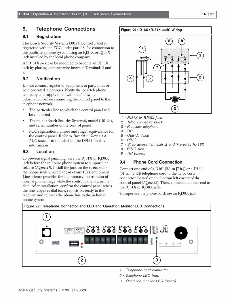
EN | 37D9124 | Operation & Installation Guide |
Bosch Security Systems | 11/03 | 39352E
9. Telephone Connections9.1 RegistrationThe Bosch Security Systems D9124 Control Panel isregistered with the FCC under part 68, for connection tothe public telephone system using an RJ31X or RJ38Xjack installed by the local phone company.
An RJ31X jack can be modified to become an RJ38Xjack by placing a jumper wire between Terminals 2 and7.
9.2 NotificationDo not connect registered equipment to party lines orcoin-operated telephones. Notify the local telephonecompany and supply them with the followinginformation before connecting the control panel to thetelephone network:
• The particular line to which the control panel willbe connected
• The make (Bosch Security Systems), model (D9124),and serial number of the control panel
• FCC registration number and ringer equivalence forthe control panel. Refer to Part 68 in Section 1.4FCC Rules or to the label on the D9124 for thisinformation
9.3 LocationTo prevent signal jamming, wire the RJ31X or RJ38Xjack before the in-house phone system to support lineseizure (Figure 21). Install the jack on the street side ofthe phone switch, wired ahead of any PBX equipment.Line seizure provides for a temporary interruption ofnormal phone usage while the control panel transmitsdata. After installation, confirm the control panel seizesthe line, acquires dial tone, reports correctly to thereceiver, and releases the phone line to the in-housephone system.
9.4 Phone Cord ConnectionConnect one end of a D161 (2.1 m [7 ft.]) or a D162(61 cm [2 ft.]) telephone cord to the Telco cordconnector located on the bottom left corner of thecontrol panel (Figure 22). Then, connect the other end tothe RJ31X or RJ38X jack.
To supervise the phone cord, use an RJ38X jack.
9. Telephone Connections
Figure 21: D166 (RJ31X Jack) Wiring
1 - RJ31X or RJ38X jack2 - Telco connector block3 - Premises telephone4 - TIP5 - Outside Telco6 - RING7 - Strap across Terminals 2 and 7 creates RF38X8 - RING (red)9 - TIP (green)
4 5 8
4 5 8
4 5 8
1
1
1
T1TRR1
2 7
5
4 6
8
2
3
1
9
7
1 - Telephone cord connector2 - Telephone LED (red)
3 - Operation monitor LED (green)
Figure 22: Telephone Connector and LED and Operation Monitor LED Connections
PHONELED
RED
ON WHENCOMMUNICATINGOFF WHEN IDLE
GRN
ENABLE
DISABLE
1211 13 1514 16 1817 19 2120 22
GROUND STARTRequires
Relay # D136 inGround
Start Socket
1
2 3

Bosch Security Systems | 11/03 | 39352E
EN | 38D9124 | Operation & Installation Guide |
9.5 Phone LED (Red)The red Phone LED lights when the control panel seizesthe phone line, and remains lit until the control panelreturns the phone line. See Figure 22 for the location ofthe red LED.
9.6 Operation Monitor LED (Green)The green Operation Monitor LED indicates the centralprocessing unit (CPU) is working. When the CPU isoperating normally, the LED flashes 0.5 second on, 0.5second off.
The green LED also serves as a ring indicator. The LEDis located on the lower right side (see Figure 22). Whenthere is ring voltage on the phone line (the phone isringing), the green LED flickers at a faster rate for theduration of each ring. Ring voltage must reach aminimum of 45 VAC before the system detects it.
9.7 Dialing FormatYou can program the system to use DTMF or pulsedialing. See Phone Parameters in the D9412G/D7412GProgram Entry Guide.
9.8 Phone Line MonitorThe control panel has a built-in phone line monitor thattests the phone line for voltage. If the D928 Dual PhoneLine Switcher is used to connect two phone lines to thecontrol panel, the control panel monitors both lines. Thenormal voltage on a telephone line is approximately48 VDC (24 VDC for some phone systems). The phoneline monitor senses trouble when the voltage on the linefalls below 3.0 VDC.
If the monitor senses trouble, it starts a programmablephone line trouble timer, which continues to run as longas the monitor senses trouble. It resets to zero when thecontrol panel senses a normal line. If the timer reachesthe delay time in the Phone Supervision program item,it begins a phone line trouble response. Programmingdetermines what the response is. See Phone Parameters inthe D9412G/D7412G Program Entry Guide.
Any time the D9412G/D7412G uses the phone line tomake a call or is on-line with RPS, it ceases to monitorthe phone line during this process. Once the phone lineon the D9412G/D7412G is no longer in use, it beginsonce again to monitor the phone line.
Bad line may test OK. The telephone line monitor usesvoltage levels to test the phone line status. In someinstances, a given telephone line can be out of servicewithout affecting the voltage on the line. The phone linemonitor can not recognize this trouble condition.
9.9 Called Party DisconnectTelephone companies provide “called party disconnect”to allow the called party to terminate a call. The calledparty must go on hook (hang up) for a fixed intervalbefore a dial tone is available for a new call. Thisinterval varies with telephone company equipment.D9124 firmware allows for “called party disconnect” byadding a 35-second “on hook” interval to the dial tonedetect function. If the control panel does not detect adial tone in 7 seconds, it puts the phone line on hook for35 seconds to activate “called party disconnect,” goes offhook and begins a seven-second dial tone detect. If nodial tone is detected, the panel dials the number anyway.Each time the number is dialed, the control panelrecords this as an attempt.
9.10 Communication FailureAfter ten attempts to reach the receiver, the controlpanel goes into communication failure. The controlpanel clears any reports in its phone buffer and aCOMM FAIL RTE # event is generated, which appearsin the display at command centers. A trouble soundercan be programmed to annunciate at the commandcenters.
One hour after the COMM FAIL RTE # is generated,the control panel attempts to send this event, ifprogrammed. If the COMM FAIL RTE # event is theonly event in the queue and cannot reach the centralstation, the command centers do not turn on the troublesounder again.
If the D928 Dual Phone Line Switcher is used, theD9124 makes a total of ten attempts before going intocommunication failure.
9.10.1 Enhanced Communication
The D9124 Control Panel transmits events over the SDIbus to a D9133TTL-E Network Interface Module. Formore information on enhanced communicationscapabilities, refer to RADXAUX1 in the D9412G/D7412GProgram Entry Guide.
9.11 Ground StartSome telephone systems require a momentary groundinput to initiate dial tone. To interface with a groundstart system, insert a D136 plug-in relay into the GNDSTART socket and set the Phone Monitor Select jumperto the GND START position.
Do not use ground start in NFPAapplications. You cannot use ground starttelephone systems for NFPA central stationprotective signaling or remote stationapplications.
Connect Terminal 10 to an earth ground so the groundstart phone systems operate properly on the D9124.
9. Telephone Connections

EN | 39D9124 | Operation & Installation Guide |
Bosch Security Systems | 11/03 | 39352E
9. Telephone Connections
9.11.1 Relay Installation
Power down the system before inserting the D136 relayinto the GND START socket. The relay socket is in thelower left corner as shown in Figure 23. The plug-inrelay is shorter than the socket it plugs into. It can beinstalled in either the left or right end of the socket.
Do not rely on relay labelling. Do not rely on thelabelling to install D136 relays. Check for the side withthree pins. The three pins go on the top side of thesocket.
Incorrect insertion does not damage therelay or the control panel, not the relatedcircuits do not function properly. Do notinsert a ground start relay if the ground startjumper is in the loop start position (seeFigure 24).
9.11.2 Phone Monitor Select Jumper
The Phone Monitor Select jumper is above the Telcoconnector point at the lower left corner of the controlpanel. Set it in the ground start position (Figure 24).
9.12 D928 Dual Phone Line Switcher9.12.1 Description
The optional D928 Dual Phone Line Switcher lets thecontrol panel transmit reports over two separate phonelines. The control panel monitors both lines. If a signalis generated and the control panel senses a line is bad, itattempts to use the other phone line to send themessage. If trouble is detected, the control panel keepsthe faulty phone line in memory.
Set the ring count above 2 on answering machines.The control panel RPS line monitor feature may notoperate correctly if an answering machine with a ringcount of less than two is connected to a phone line usedby the D928 Module.
Two phone lines are required in UL Listed fireapplications.
9.12.2 Operation
See Phone in the D9412G/D7412G Program Entry Guidefor phone supervision and reporting options. Set theTwo Phone Lines prompt to YES to use the D928.
When the D928 is installed, the control panel alternatesbetween Phone Line 1 and Phone Line 2 to send its firstreport. For example, on day one the control panelattempts to first communicate on Phone Line 1. On daytwo, the panel switches and attempts to communicate onPhone Line 2.
Any time the control panel resets or powers down/up,the next reported event always attempts to call out onPhone Line 1 first.
If Phone Line 2 is not in service on Day 2, the controlpanel switches to the primary phone line to send thereport.
With the D928 Dual Phone Line Switcher installed, thecontrol panel uses two phone lines (primary andsecondary) to dial up to four phone numbers.
Figure 23: Terminals 7 and 8 Relays and GroundStart
1 - Top2 - Left3 - Bottom4 - Gnd Start5 - SW Aux6 - ALT alarmNote: The D136 relays are inserted with the threepins towards the top side.
1
2
3
65
4
Figure 24: Phone Monitor Select
1 - Loop start position 2 - Ground start position
GROUND FAULT DETECTEnabledDisabled
LOOP
PHONE MONITOR SELE
GROUND STARTRequires
Relay # D136 inGround
Start Socket
GND1
2

Bosch Security Systems | 11/03 | 39352E
EN | 40D9124 | Operation & Installation Guide | 9. Telephone Connections
When using a primary and backup device within aRoute Group #, the control panel makes two attemptson the primary phone line using the Primary Device #as programmed. If these two attempts fail, the controlpanel switches to the secondary phone line using theBackup Device # as programmed. This patterncontinues for a total of ten attempts. After tenunsuccessful attempts, the control panel generates aComm Fail event for the given Route Group #.
9.12.3 Watchdog Feature
The D928 watchdog circuit monitors the control panel’sCPU for proper operation. If the CPU fails, the buzzeron the D928 sounds, as does the sounder on the controlpanel. This sounder cannot be reset when the CPU fails.The D928 stops sounding only when the control panelCPU returns to normal operation.
9.12.4 Installing the D928
Mounting
Mount the D928 on the lower right side of the enclosureusing the screws provided with the switcher.
Wiring
The D928 has two flying leads. The green lead monitorsAC power. The black lead provides surge protection forthe two incoming phone lines. The black lead is also theground reference for the AC LED.
1. Connect the green lead from D928 to Terminal 1.2. Connect the black lead from D928 to Terminal 9.
Phone Connections
1. Plug one end of the ribbon cable (provided with theD928) into J4 on the D928. Plug the other end intothe accessory connector on the control panel.
2. Plug one end of the D162 (61 cm [2 ft.]) phone cord,provided with the D928, into J3 on the D928. Plugthe other end into Telco on the control panel.
3. Plug one end of a D161 (2.1 m [7 ft.]) or D162 (61 m[2 ft.]) phone cord into J1 on the D928. Plug theother end into the RJ31X or RJ38X for the primaryphone line.
4. Plug one end of a D161 or D162 phone cord into J2on the D928. Plug the other end into the RJ31X orRJ38X for the secondary phone line.
9.12.5 D928 Status LEDs
Four LEDs, mounted on the front edge of the D928Module, show the status of AC power for the controlpanel, status of the two phones lines, andcommunication failure (Figure 25). When programmedand operating normally, only the green AC power statusLED is lit.
AC Power LED
The green AC Power Status LED lights when there isAC power at Terminals 1 and 2 on the control panel.
1 - Connect to ACCESSORY CONNECTOR withribbon cable.
2 - Green to Terminal 13 - Black to Terminal 94 - AC Power LED (green)5 - Phone jack to primary phone line - RJ31X6 - Primary Fail LED (yellow)
7 - Phone jack to secondary phone line8 - Secondary Fail LED (yellow)9 - Phone jack to TELCO Connector10 - Communications Fail LED (yellow)
11 - Buzzer
Figure 25: D928 Dual Phone Line Switcher
+
+
1
4
3
2
5
6
7
8
9
10
11

EN | 41D9124 | Operation & Installation Guide |
Bosch Security Systems | 11/03 | 39352E
10. Programming1. If you have not created a control panel program,
review the D9412G/D7412G Program Entry Guide andcopy the control panel or use the default record toavoid erasing the default program for the D9124.
2. Make sure you have all the required accessorymodules installed for the features you want to use.
3. Load the D5500 RPS onto a PC and create aprogram for your D9124 System. Refer to the RPSOperations Manual for complete information on usingthe D5500 RPS.
4. Record your program choices on the D9124 ProgramRecord Sheet and fill in the Point Chart Label.
10.1 Programmer Connector (J7)10.1.1 Using a D5360
To connect and disconnect a local PC for programmingthe control panel using the D5500 RPS:
1. Connect the D5360 to your PC serial port. TheD5360 has a DB-9 female serial connector. If thisdoes not fit your PC, you need an adapter.
2. Connect the supplied connector cord (modular toMolex) from the D5360 to the programmerconnector port ( J7) on the control panel.
3. Lock the Reset Pin (Figure 8).
SDI Troubles are reported after 30 secondsif the Reset Pin is not locked and the D5200Programmer remains connected.
4. Perform the desired programming function (send orreceive program).
If you send a program to the control panel,the control panel sends a Prog Access OKReport 10 seconds after you exit the handleror when you disconnect the programmer.Program the Diagnostic Reports prompt inRouting YES to send this report.
5. Disconnect the programmer.
6. Unlock the Reset Pin to accept the programmingchanges and reset the control panel. Note that thecontrol panel on-board buzzer sounds for 1 secondwhenever the control panel resets.
10.2 Programmable Test FeaturesSee Section 11.0 Testing the System for information onoperating these test features.
10.2.1 Fire Test
The Fire Test lets one person perform a Fire Testwithout assistance. This test:
• Reports to the receiver when you start/end the test.
• Annunciates local sounders without sending reportsto the receiver.
• Automatically resets smoke detectors. You need notpress [SENSOR RESET] to reset sensors aftertesting each device.
• Prints a record of each alarm test response when alocal printer is installed.
Fire Test suppresses alarms and troubles. Allalarm and trouble reports to the receiver aresuppressed when Fire Test is in progress.
Make sure the Sensor Reset is enabled when you areusing the Fire Test. Fire Test is described in Section 11.0Testing the System and in the User’s Guide provided withthe D1255 and D1255R Command Centers.
10.2.2 Walk Test
The Walk Test tests points that turn on and off as part ofan intrusion system. This test is performed in the samemanner as the Fire Test.
10.2.3 Service Walk Test
The Service Walk Test tests all points and is performedin the same manner as the Fire Test.
10.2.4 Automatic Test Reports
The D9124 can generate automatic Test Reports, whichare used to test the phone lines. NFPA 72 CentralStation and remote station standards require you to senda Test Report at least once every 24 hours.
Refer to Section 2.2.6 Skeds for programming Test Reportschedules. See S## Function Code Selection Number 9–TestReport in the D9412G/D7412G Program Entry Guide forprogramming requirements. You can defer the testreport if the control panel generates a report other thanthe Automatic Test Report. Use the additional parameterS## DEFER TEST to postpone the test until the nextscheduled test report.
Program the Test Report to send additional system eventinformation. See Expand Test Rpt in the Phone section ofthe D9412G/D7412G Program Entry Guide for moreinformation.
See Section 9.12 D928 Dual Phone Line Switcher fordetails on phone line failure reports.
10. Programming

Bosch Security Systems | 11/03 | 39352E
EN | 42D9124 | Operation & Installation Guide | 10. Programming
When setting test times, a D1255 orD1255R Command Center is required to setthe control panel clock and calendar. Seethe C-Time/Date section of the SecuritySystem User's Guide supplied with thecommand center for operating instructions.

EN | 43D9124 | Operation & Installation Guide |
Bosch Security Systems | 11/03 | 39352E
11. Testing the System11.1 Fire TestTest fire points to confirm they function properly. Youcan review untested points at the command center tohelp pinpoint any problems.
Upon initiation, the Fire Test tests the fire alarm outputand activates the command center fire sounder for 2seconds. The AC disables for 4 minutes to test thesystem’s battery power. If the battery cannot maintainthe system for the 4-minute period, the command centerappears to go dead. At the end of the 4-minute period,AC returns to the system and the control panel restores.A message is sent to the receiver upon initiation andcompletion of the Fire Test.
During the Fire Test, no alarms are sent to the centralstation.
If there is no activity on the system for 20 minutes, thesystem automatically exits from the Fire Test and sends arestoral message to the receiver.
11.1.1 Using Fire Test
1. Press [ESC] on the D1256 Command Center toenter the menu.
2. Press [NEXT] repeatedly until you reach the FIRETEST ? prompt and then press [ENT].
The display shows ### PTS TO TEST.
3. Activate the detection devices one at a time to faulteach point.
As you activate each point, your command centershows the point text for 60 seconds and rings the firesounders for 2 seconds. This verifies the detectiondevice is working properly. The D9124 Systemautomatically resets smoke detectors.
When a resettable point (such as a smoke detector) isfaulted, the display shows SENSOR RESETTING for5 seconds. During this time power is removed fromsmoke power relays.
Activating a point more than once does notincrement the test count. The command center emitsa brief tone and displays the point text each timeyou fault the point allowing you to test multipledevices assigned to one point.
4. When all 24-hour points are tested, 0 PTS TOTEST appears. Press [ESC]. The displaymomentarily shows ALL PTS TESTED beforereturning to idle text.
5. During the Fire Test you can see the points thatremain untested. When point text appears, press[ESC].
6. When the display shows ### PTS TO TEST press[ESC].
7. VIEW UNTESTED ? appears. Press [ENT].
8. The display shows ### PTS UNTESTED. Press[NEXT] to see a list of the points that are not yettested. Continue pressing [NEXT] to scroll throughthe list.
9. Press [ESC] to resume the Fire Test. ### PTSUNTESTED appears.
10. Press [ESC]. The display shows ### PTS TOTEST and you can resume testing points.
11. Press [ESC] twice to end the Fire Test.
Automatic time-out returns the system to idletext. If there is no point or command centeractivity for 20 minutes, the Fire Test endsautomatically and the D9124 System sendsa restoral message to the receiver. Thecommand center returns to idle text.
11.2 Service Walk TestThe Service Walk Test differs from the standard WalkTest. POPITs whose addresses are set for a pointnumber not programmed in the control panel appear inthe Service Walk Test.
The Service Walk Test is only available atcommand centers with a panel-wide scope.Refer to the Command Center sections inthe D9412G/D7412G Program Entry Guidefor a description of command center scope.
Fire and other 24-hour points do not transmitreports to the receiver during the ServiceWalk Test.
To perform a Service Walk Test:
1. Choose a command center with panel-wide scope toconduct the test. Be certain the display shows theidle disarmed text.
2. Press [MENU] to enter the Function List, or press[9] [9] [ENT] to show the first item in the ServiceMenu.
3. Press [NEXT] to step through the menu items untilSERVICE WALK? appears in the display.
4. Press [ENT]. If you programmed Service Walk Testaccess to be restricted by authority level, ENTERPASSCODE appears in the display.
11. Testing the System
Bosch Security Systems | 11/03 | 39352E
EN | 44D9124 | Operation & Installation Guide |
5. Enter a passcode assigned an authority level withaccess to the Service Walk Test function. Then press[ENT].
6. When 246 PTS TO TEST appears, test the firstdetection device.
As you fault the detection devices, the commandcenter emits a short tone, briefly displays the pointtext for the point tested, and returns to the points totest display.
Extra Points display default text. If youincorrectly set the addresses on a POPIT toa point number that is not in your controlpanel program, the default text for that pointnumber (POINT ###) displays when youfault the point. The D9124 Program RecordSheet shows the default text for all points.
Faulting the point a second time produces the toneand displays the point text, but does not reduce thePts to Test count.
7. During the Service Walk Test, view the points thatremain untested by pressing [ESC] when point textappears.
11. Testing the System
8. When the display shows ### PTS TO TEST, press[ESC].
9. VIEW UNTESTED ? appears. Press [ENT].
10. When ### PTS UNTESTED appears, press[NEXT] to see a list of the points that were not yettested. Continue pressing [NEXT] to scroll throughthis list.
11. To resume the Service Walk Test, press [ESC].
12. When the display shows ### PTS UNTESTED,press [ESC].
13. ### PTS TO TEST appears and you can resumetesting points.
14. Press [ESC] twice to end the Service Walk Test.After testing the last point, the display shows 0 PTSTO TEST. Press[ ESC]. The display momentarilyshows ALL PTS TESTED before returning to idletext.
Automatic time-out returns the system to idle text. Ifthere is no point or command center activity for20 minutes, the Walk Test ends automatically and theD9124 System sends a restoral message to the receiver.The command center returns to idle text.

EN | 45D9124 | Operation & Installation Guide |
Bosch Security Systems | 11/03 | 39352E
12. Troubleshooting12.1 IntroductionUse this guide to help troubleshoot problems with theD9124 Control Panel. To prevent problems fromoccurring, read the preceding sections and the D9412G/D7412G Program Entry Guide to verify the control panelis correctly installed and programmed.
12.2 Self-Diagnostic TestsD9124 Control Panel performs a series of self-diagnostictests of hardware, software, and programming at start upand reset.
12. Troubleshooting
Buzzer sounding is normal at start-up: The on-boardbuzzer, located on the lower right corner of the controlpanel, sounds as the D9124 performs self-diagnostic testsat start up and reset. These tests take less than 2 seconds.If all tests complete successfully, the buzzer turns off.The control panel continues periodic internal testingduring normal operation. If a fault is detected duringtesting, the buzzer sounds.
Table 16 identifies system problems that display duringself-diagnostic tests and describes how to troubleshootthem.
Table 16: Self-Diagnostic Tests
Problem Diagnosis SolutionCALL FOR SERVICE appears inthe command center display. Nobuzzer sounds at the commandcenter.
A command center stopped receivingdata from the control panel.
Check the wiring for opens, grounds, or shorts.
COMM FAIL ROUTE # appears incommand center displays.
The control panel made tenunsuccessful attempts to report to thereceiver.
• See Section 12.6 Communication Failure.• Press [ESC] to silences the buzzer. The
display clears when communication restores(such as the receiver acknowledging areport).
PANEL BROKEN appears in thedisplays of all command centers,the command center buzzer sounds,and the green Operation MonitorLED stops flashing or is off.
A hardware or software problemoccurred.
Pressing [ESC] does not silence the buzzer.Return the control panel to Bosch SecuritySystems for repair. See Section 3. Installation forinformation on installing a working control panel.
PARAM FAIL alternates with theidle text at the command centers,the command center buzzer sounds,the green Operation Monitor LEDcontinues flashing, and the controlpanel sends a Bad Param CksumReport to the receiver.
The program is corrupted. Pressing [ESC] might silence the buzzer.Silencing the buzzer does not correct theproblem. The corrupted copy of the program inthe control panel must be replaced. Load a newcopy of the complete program. The displays clearwhen the control panel is reset after loading anew program. See Section 10. Programming.
SERVC AC FAIL appears in thecommand center displays.
AC power was interrupted atTerminals 1 and 2.
Press [ESC] to silence the buzzer. Restoringpower clears the display.
Note: Program the control panel to send an ACFail Report to the receiver.
SERVC BATT LOW appears in thecommand center displays.
Battery voltage at Terminals 4 and 5fell below 12.1 VDC.
• See Section 12.11 Battery and PowerReports for probable causes and remedies.
• Press [ESC] to silence the buzzer. Thedisplay clears when battery voltage reaches13.7 VDC.
SERVC BATT MSING appears inthe command center displays.
The control panel cannot detect abattery at Terminals 4 and 5.
Press [ESC] to silence the buzzer. Restoring thebattery clears the display.
Note: Program the control panel can to send aBattery Missing Report to the receiver.

Bosch Security Systems | 11/03 | 39352E
EN | 46D9124 | Operation & Installation Guide |
12.3 Control Panel ProgrammingBecome familiar with the basic operation of the D5200 programmer before attempting to program the control panel(see the D5200 Operation Manual).
Table 17 identifies problems that can occur at the control panel and describes how to troubleshoot them.
12. Troubleshooting
Table 16: continued
Problem Diagnosis SolutionSERVC GND FAULT appears incommand center displays.
The control panel detected an earthground fault.
Follow the steps in Section 12.16.1 IsolatingGround Faults. See also Connecting Earth Groundin the D9412G/D7412G Operation and InstallationGuide.
SERVC KEY PAD appears at othercommand centers connected to thecontrol panel, and the control paneltransmits an SDI Failure Report tothe receiver.
The control panel lost contact witha supervised command center.
Press [ESC] to silence the buzzer. The displaysclear when contact with the missing commandcenter restores.
SERVC 9210 #n appears at theother command centers connectedto the control panel and the controlpanel transmits an SDI Failure ##Report to the receiver.
The control panel lost contact witha D9210B Access InterfaceModule.
Check the wiring for opens, grounds, or shorts.
SERVC PH LINE #1 (SERVCPH LINE #2) appears incommand center displays.
The control panel detected a phoneline fault.
See Section 12.5 Phone Line. Also, refer to PhoneLine Monitor in the Telephone Connections sectionin the D9412G/D7412G Operation and InstallationGuide for a complete description.
SERVC PRINTER appears incommand center displays.
The control panel lost contact witha supervised printer.
Press [ESC] to silence the buzzer. The displaysclear when contact with the missing printer restores.
Table 17: Control Panel Programming
Problem Diagnosis SolutionThe programmer is not correctlyconnected to the control panel.
• Verify the data/power cord is plugged into thecommunicator port on the D5200.
• Verify the data/power cord is plugged securelyinto the control panel programmer connector.
• Check each conductor in the data/power cordfor continuity.
The programmer displays PLUG INPANEL when you press [SEND] or[RECEIVE].
AC induction through theon-board point sensor loops, theDATA bus, or the ZONEX bus.
• Verify a proper earth ground at Terminal 10.• Disconnect on-board point sensor loops, data
bus(Terminals 30 and 31), and ZONEX bus(Terminals 25 to 28).
After plugging in the programmer,the control panel transmits SDITrouble Reports for supervised SDIdevices (such as command centersand printer interface modules). AllSDI devices stop operating.
The control panel handler was notentered within 30 seconds ofplugging in the programmer.
• Enter the control panel handler within 30seconds of plugging in the programmer.
• Once the SDI reports are generated, sendingor receiving a handler or disconnecting theprogrammer returns the SDI devices to normaloperation.

EN | 47D9124 | Operation & Installation Guide |
Bosch Security Systems | 11/03 | 39352E
12.4 Command CentersTable 18 identifies problems that can occur at command centers and describes how to troubleshoot them.
12.5 Phone LinePhone line problems that are not corrected can choose the control panel to go into communications failure. TheD9124 can be programmed to monitor one or two phone lines. Refer to the D9412G/D7412G Program Entry Guide forprogramming instructions.
If the phone line monitor is enabled, SERVC PHONE LINE #1 (#2 if two lines are used) appears in the commandcenter display when the control panel detects a problem on the phone line.
Table 19 identifies problems that can occur with phone lines and describes how to troubleshoot them.
12. Troubleshooting
Table 18: Command Centers
Problem Diagnosis Solution• More than one command
center has the samesupervised address.
• Use a supervised address in one command center only or usea different supervised address for each command center.
Command centers showerratic behavior. Forexample, the pip thatconfirms you pressed akey echoes.
• Data connections (yellowand green wires) on one ormore command centers arereversed, or only one wireis connected.
• Verify the yellow and green data wires are correctly connectedon all command centers.
NO AUTHORITYdisplays at thecommand center whenyou enter yourpasscode to perform afunction.
• Check the User Interface section of the program to be sure thefunction is enabled for the authority level assigned to thepasscode in the Passcode Worksheet section of the program.
• Check the Passcode Worksheet section of the programconfirm the passcode is assigned to the area where you areattempting to perform the function.
• Check the Passcode Worksheet section of the program to seeif the passcode is restricted by a user window.
• Check the Area Parameters section of the program confirm thearea in which you are attempting to perform the function isturned on.
Table 19: Phone Line
Problem Diagnosis SolutionSERVC PH LINE #1(or #2 if two lines areused) appears in thecommand centerdisplay.
The control panel phone linemonitor detects a phone line asfaulted.
• Verify the telephone cord is correctly connected to the phonejack and the control panel.
• Verify the Ground Start Jumper is in the correct position.• If using a ground start phone line, verify a D136 relay is
correctly installed in the Ground Start Relay socket.• Verify the phone jack (RJ31X or RJ38X) is wired correctly. The
incoming phone line must be wired to Terminals 4 and 5. Thein-house phone system must be wired to Terminals 1 and 8.
• Verify all telephones are on-hook. Leaving a telephone on holdafter the other party hangs up creates an off-hook condition.Verify there are no phones are on hold.
• If completing the previous steps does not restore the phoneline, meter the line. If your readings are below 3.0 VDC,contact your telephone company repair service.

Bosch Security Systems | 11/03 | 39352E
EN | 48D9124 | Operation & Installation Guide | 12. Troubleshooting
12.6 Communication FailureThe control panel goes into communication failure after ten unsuccessful attempts to reach the receiver. Check Table19 in Section 12.5 Phone Line to verify there is no problem with the phone lines at the installation. If the phone linesare good, monitor the lines (preferably at the receiver) for the symptoms shown in Table 20.
Table 20: Communication Failure
Problem Diagnosis SolutionThe line rings but theD6500/D6600 Receiver does notpick up. The Ring Indicator LED onthe line card does not light. Youcannot hear the ring with aheadset at the receiver location.
Line is not ringing at thereceiver.
• Verify the lines are correctly connected to thereceiver.
• Verify correct prefixes and phone numbers for thereceiver are programmed into the control panel.
• If completing the previous steps does not correctthe problem, contact your telephone company repairservice.
The control panel cannot call outwhen all 246 points are faulted.
The total current draw is toomuch for the control panel.
Put the command centers on a separate power supplyfor the maximum current draw from points in alarm.
The line rings but the receiverdoes not pick up. The RingIndicator LED on the line cardlights. You can hear the ring withtest set at the receiver location.
Line card in the receiver may befaulty.
Review the receiver manuals for troubleshootingprocedures.
• Calls are not reaching thereceiver.
• Verify the correct prefixes and phone numbers forthe receiver are programmed into the control panel.
• Confirm the phone lines are not shorted betweenthe phone company's equipment and the receiver byplacing a call to the number for the receiver. If youhear the line ring and the ring detector does notlight, or if you hear a busy signal and the green OnLine (OL) indicator is not lit, call the phone companyfor service.
The control panel reaches a busysignal for all ten attempts to reachthe receiver.
• The receiver's call load istoo great.
• Additional line cards and phone lines might beneeded for the receiver.
The receiver answers the call andprovides an acknowledgment tone,but the communicator does nottransmit reports.
The receiver is not producingthe correct acknowledgmenttone.
Verify the receiver is producing a 1400 Hz, 2300 Hz, orModem IIIa2 acknowledgment tone.
The control panel does notconnect to the central station.
The D136 relay used for groundstart phone systems is insertedincorrectly.
Insert the D136 relay in the GND START socketcorrectly. Also, ensure the phone line is connected andthe phone jack is wired properly. Refer to Section 9.11.1Relay Installation for instructions.
• The receiver is notcompatible with the panel’stransmission format.
• Make sure the receiver is compatible with the formatthe control panel is using (either BFSK or Radionics’Modem IIIa2 Communications Format). See Phone inthe D9412G/D7412G Program Entry Guide.
• The D6500 Receiver requires MPU and Line CardEPROM revision 8.00 or higher, or use the D6600Receiver.
The receiver answers the call andprovides an initial handshakeacknowledgment, but does notacknowledge the panel’s reporttransmission with a kiss-offacknowledgment.
• Noisy phone lines areinterfering with reporttransmission.
• Try making a voice call to the receiver on the line toverify the noisy condition. It might be necessary tohave the phone company check the lines.

EN | 49D9124 | Operation & Installation Guide |
Bosch Security Systems | 11/03 | 39352E
12. Troubleshooting
12.7 PointsIf the switches on a POPIT are set incorrectly, it can create both missing and extra points. When a missing point isfound, perform a Service Walk Test to search for extra points. See the Owner’s Manual for test instructions.
Table 21 identifies problems with points and describes how to troubleshoot them.
Problem Diagnosis Solution• POPIT is not connected or
incorrectly connected to thedata expansion loop.
• Verify a POPIT Module programmed for the missing pointnumber is connected to the data expansion loop of thecorrect ZONEX Module. Points 9 to 127 connect toZONEX Module 1. Points 129 to 247 connect toZONEX Module 2.
• Meter each POPIT to verify the polarity of the dataexpansion loop. Voltage should be 9 VDC to 13 VDC ateach POPIT.
• D8128D OctoPOPIT isinstalled at the last addresson the ZONEX bus.
• Install a D8125 POPEX and D9127 POPITs for points121 to 127 on ZONEX 1 and for points 241 to 247 onZONEX 2.
• Sensor loop switch (1 to 8)is turned off on OctoPOPIT.
• If the sensor loop switch on an OctoPOPIT is turned offfor a programmed point, the point reports as missing.
Point appears as missing atthe command centers and inreports to the receiver.
• POPIT is not programmedcorrectly.
• Verify the switches on the POPIT are set for the missingPOPIT number. Incorrectly set switches can cause bothmissing and extra POPITs.
• Performing a Service Walk Test to search for extra pointscan help diagnose the problem.
Problem with data expansionloop.
See the troubleshooting information in Section 12.8 D8125POPEX Data Expansion Loosp.
Points intermittently appearas missing. Points areerratic. Debounce Count parameter set
at 1. If an off-board point is intransition between normal andfaulted conditions as the panelscans it, it appears as missing.
• Leave the Debounce Count at the default of 2.• Decreasing the Debounce Count to 1 can cause points
to appear as missing. Increasing the Debounce Countcan cause missed alarms.
One or more points remain introuble or alarm with alldevices connected to thesensor loops normal.
• The sensor loop is open,shorted, or grounded.
• Remove the sensor loop from the control panel or POPITand meter it for continuity. There should be no more than100 Ω resistance, plus the value of the EOL resistor onthe wires. If you meter less resistance than the value ofthe EOL resistor, check the wiring for shorts.
• Opens, shorts, or groundscause troubles or alarmsdepending on pointprogramming.
• With the wires for the loop removed, meter them forcontinuity to ground. A ground before the EOL resistoron an on-board point’s sensor loop is interpreted as ashort. A ground on a sensor loop for a POPIT point isinterpreted as an open.
• The Sensor Reset waspressed when the alarm ortrouble was generated.
• No action is required because during a sensor reset thecontrol panel ignores input from all points in the samearea that was programmed for sensor reset.
Faulted points do notgenerate alarms or troublesas programmed.
• Two points are programmedwith the same address.
• Points programmed with the same address do notfunction correctly. Confirm there are no duplicated pointaddresses.
Table 21: Points
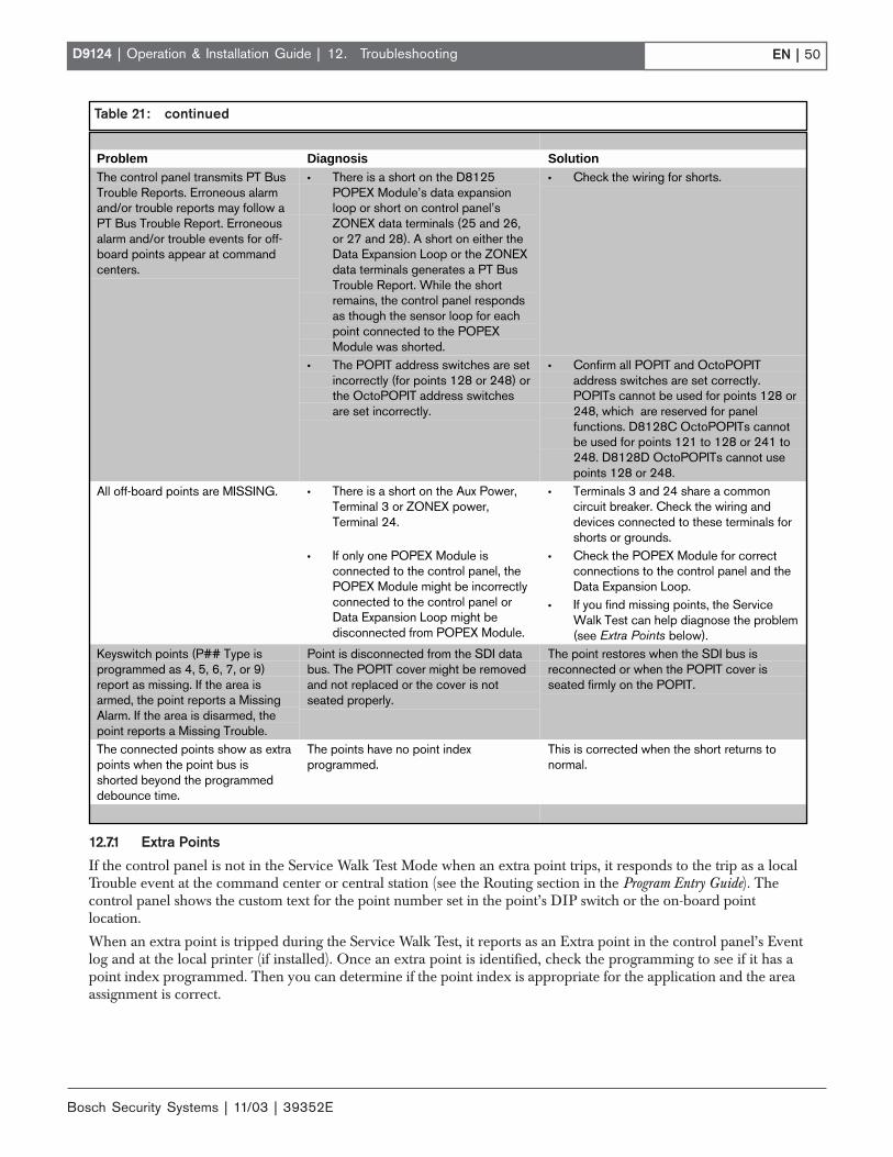
Bosch Security Systems | 11/03 | 39352E
EN | 50D9124 | Operation & Installation Guide |
12.7.1 Extra Points
If the control panel is not in the Service Walk Test Mode when an extra point trips, it responds to the trip as a localTrouble event at the command center or central station (see the Routing section in the Program Entry Guide). Thecontrol panel shows the custom text for the point number set in the point’s DIP switch or the on-board pointlocation.
When an extra point is tripped during the Service Walk Test, it reports as an Extra point in the control panel’s Eventlog and at the local printer (if installed). Once an extra point is identified, check the programming to see if it has apoint index programmed. Then you can determine if the point index is appropriate for the application and the areaassignment is correct.
12. Troubleshooting
Table 21: continued
Problem Diagnosis Solution• There is a short on the D8125
POPEX Module’s data expansionloop or short on control panel’sZONEX data terminals (25 and 26,or 27 and 28). A short on either theData Expansion Loop or the ZONEXdata terminals generates a PT BusTrouble Report. While the shortremains, the control panel respondsas though the sensor loop for eachpoint connected to the POPEXModule was shorted.
• Check the wiring for shorts.The control panel transmits PT BusTrouble Reports. Erroneous alarmand/or trouble reports may follow aPT Bus Trouble Report. Erroneousalarm and/or trouble events for off-board points appear at commandcenters.
• The POPIT address switches are setincorrectly (for points 128 or 248) orthe OctoPOPIT address switchesare set incorrectly.
• Confirm all POPIT and OctoPOPITaddress switches are set correctly.POPITs cannot be used for points 128 or248, which are reserved for panelfunctions. D8128C OctoPOPITs cannotbe used for points 121 to 128 or 241 to248. D8128D OctoPOPITs cannot usepoints 128 or 248.
• There is a short on the Aux Power,Terminal 3 or ZONEX power,Terminal 24.
• Terminals 3 and 24 share a commoncircuit breaker. Check the wiring anddevices connected to these terminals forshorts or grounds.
All off-board points are MISSING.
• If only one POPEX Module isconnected to the control panel, thePOPEX Module might be incorrectlyconnected to the control panel orData Expansion Loop might bedisconnected from POPEX Module.
• Check the POPEX Module for correctconnections to the control panel and theData Expansion Loop.
• If you find missing points, the ServiceWalk Test can help diagnose the problem(see Extra Points below).
Keyswitch points (P## Type isprogrammed as 4, 5, 6, 7, or 9)report as missing. If the area isarmed, the point reports a MissingAlarm. If the area is disarmed, thepoint reports a Missing Trouble.
Point is disconnected from the SDI databus. The POPIT cover might be removedand not replaced or the cover is notseated properly.
The point restores when the SDI bus isreconnected or when the POPIT cover isseated firmly on the POPIT.
The connected points show as extrapoints when the point bus isshorted beyond the programmeddebounce time.
The points have no point indexprogrammed.
This is corrected when the short returns tonormal.

EN | 51D9124 | Operation & Installation Guide |
Bosch Security Systems | 11/03 | 39352E
12.8 D8125 POPEX Data Expansion LoopsElectromagnetic interference (EMI), excessiveresistance, or intermittent grounds, shorts, or opens onthe data expansion loop can cause erratic or intermittentfunctioning of points. If EMI is a problem, see Section12.9 EMI on Long Wire Runs.
AC induction on the data expansion loops must be lessthan 1.0 VAC. If EMI is not suspected as the cause ofthe problem, follow the procedure in Section 12.8.1 tofind the source of problems on the data expansion loop.You can also use the Zonex Point Identification ValidationProcess (P/N: 43049) for a detailed procedure andworksheets to identify and validate all points.
12.8.1 Metering the Loops
Before performing the following procedure to meter thedata expansion loops, check Table 22 to verify thecorrect gauge wire was used for the length of the dataexpansion loops.
When metering the loop, monitor it long enough toobserve an intermittent problem.
To meter the data expansion loop without connectedPOPITs:
1. Disconnect the loop from the POPEX Module.
2. Twist the positive and then the negative wirestogether at each POPIT location so the positive andnegative wires are continuous to the last POPITlocation.
3. At the last POPIT location, twist the end of thepositive wire to the negative wire to form onecontinuous loop.
4. Meter the loop for continuity from the point whereit connects to the POPEX Module. Resistance forthe entire loop must be less than 60 Ω. If there is nocontinuity, find and repair the open on the loop.
5. Still metering for continuity, untwist the negativeand positive wires at the last POPIT location. If themeter does not show an open condition, find andrepair the short on the loop.
6. Twist the positive and negative wires at the lastPOPIT location together.
7. Meter the loop for continuity to Terminal 10 (earthground). If there is continuity, find and remove theforeign ground on the loop.
8. Meter the loop to Terminal 10 for AC voltage. ACinduction on data expansion loops must be less than1 VAC. Try using shielded cable to reduce ACinduction if the AC voltage exceeds 1 VAC.
12.9 EMI on Long Wire RunsEMI can cause problems on long wire runs for serialdevices such as command centers and POPITs. Usingshielded cable reduces the effect of this interference.Some potential sources of noise on a long wire runinclude:
• Radio or television transmitter site
• Amateur radio operator’s transmitter site
• Computer network system
• Heavy machinery (large electrical motors)
• PBX telephone system
• High voltage electrical equipment or transformerssuch as arc welders, certain medical and dentalequipment, and so on
• Public service office using radio communications(fire department and police department, and so on)
• Close proximity to electrical lines, telephonecabling, or fluorescent lighting fixtures
There are many other possible sources of noise. If noiseis a problem, use shielded wire. Connect the drain wirefrom the shielded cable to Terminal 10 on the controlpanel.
The drain wire must have continuity from the controlpanel to the last device on the wire run. If the cable iscut to install devices between the last device and thecontrol panel, make sure you reconnect the drain wire toinsure continuity to the last device.
If continuity is not maintained between the controlpanel and the last device, the shielded cable canaggravate potential noise problems rather than eliminatethem. Connecting the drain wire to ground at other thanTerminal 10 on the control panel can also produceproblems. Do not connect the drain wire to any otherground source.
12. Troubleshooting
Table 22: Data Expansion Loop Wire Specifications
Maximum Length of all Data Expansion Loops CombinedAWG Length in meters (feet)22 548 (1800)20 881 (2890)18 1402 (4600)16 2231 (7320)14 3551 (11,650)

Bosch Security Systems | 11/03 | 39352E
EN | 52D9124 | Operation & Installation Guide | 12. Troubleshooting
12.10 Checking Shielded CableIf improperly installed, shielded cable can createproblems rather than solve them.
To check shielded cable for proper installation:
1. Remove the drain wire for the shield from Terminal10.
2. Meter the drain wire for continuity to Terminal 10(earth ground). If there is continuity, find andremove the foreign ground on the drain wire.
3. Reconnect the drain wire to Terminal 10.
4. Meter the shield at the far end of the cable (lastPOPIT location on data expansion loops) forcontinuity to a ground reference. If there is nocontinuity, find and repair the open in the shield.Solder and tape all connections.
12.11 Battery and Power ReportsYou can program the control panel to transmit bothBattery and AC Power Status Reports (see the D9412G/D7412G Program Entry Guide).
If Battery or AC Power Reports are a problem:
1. Make sure the control panel power supply is notoverloaded. Review Section 7.0 Power Supplies andSection 12.14 Overloaded Power Supply.
2. Verify there is at least 16.5 VAC on Terminals 1 and2. The outlet the transformer is plugged into shouldmeter between 110 VAC and 120 VAC.
3. Confirm the output for the transformer connected toTerminals 1 and 2 is rated for 16.5 VAC and at least40 VA.
4. Disconnect the transformer from Terminals 1 and 2and meter the battery at Terminals 3 and 4. A fullycharged battery shows approximately 13.8 V.
5. Make sure the battery is a 12 V sealed lead-acidtype. It should be rated at 7 Ah or greater,depending on the NFPA classification of theinstallation.
6. If it takes longer than 60 seconds to detect a missingbattery, make sure there is a good earth groundconnection. Also make sure there are no externaldevices that can induce voltage.
12.12 Watchdog Reset ReportsThe control panel sends a Watchdog Reset Reportwhenever the control panel CPU is interrupted andrestarts its normal operating sequence. The on-boardbuzzer sounds briefly during the Watchdog Reset. Thecontrol panel returns to normal operation immediatelyafter resetting.
The most common cause of CPU interruption andWatchdog Reset Reports is static discharge to thecontrol panel. Static discharges may also corrupt thecontrol panel's program. The D9124 displays PARAMFAIL at the command centers and sends a ParamCksum Fail Report if the program is corrupted.
Shorting Terminals 3, 6, 7, 8, 24, or the programmingconnector to ground can also cause a Watchdog Reset.Remove the short to continue normal operation.
A single isolated Watchdog Reset Report does not meanthe control panel must be replaced. If experiencingfrequent reports, contact Bosch Security SystemsCustomer Service for help.
Touch Terminal 10 first: If the on-board buzzer soundsbriefly when the control panel is first touched, any staticcharge being carried is being discharged to the controlpanel. The control panel can generate Watchdog Resetand/or Param Fail events. Always touch Terminal 10(control panel’s earth ground connection) beforebeginning work on the control panel.
12.13 Runaway Reports to the ReceiverUsing D8128 or D8128A instead of the D8128DOctoPOPIT Module can cause Runaway Reports to thereceiver on AC failure. Make sure you replace all D8128or D8128A OctoPOPITS with the D8128D Module.
12.14 Overloaded Power SupplyIf the load on the control panel's power supply exceedscapacity, it follows a routine to protect itself and thebattery. The control panel sends reports to the centralstation at several points during this routine.
Keep in mind the AC power remains at Terminals 1 and2 throughout the scenario that follows:
• The control panel operates normally with a goodbattery, AC is present at Terminals 1 and 2, andauxiliary power load is under 1.4 A.
• The combined load on Terminals 3, 6, 7, 8, 24, and32, accessory connector, and programmingconnector exceeds and remains above 1.4 A. Devicefailure or premises wiring ground faults may causethe increased load.
• The yellow Charging Status LED turns on,indicating the control panel is drawing on thebattery to support the increased load.
• The battery begins to drain. When voltage drops to12.1 V, the control panel sends a Low Battery Reportand turns on the red Low Battery LED.
• When the battery drops to 10.2 V, the control paneldisconnects it to protect it from deep discharge.

EN | 53D9124 | Operation & Installation Guide |
Bosch Security Systems | 11/03 | 39352E
12. Troubleshooting
• If AC is still present, the control panel removespower to Terminals 3, 6, 7, 8, 24, and 32, and theprogramming connector to protect its power supply.The green Operation Monitor LED turns off, but thecontrol panel continues operating.
• The control panel sends Battery Missing, Pt BusTrouble, and SDI Failure Reports.
• If a D928 Module is connected, it begins sounding.• After approximately 60 seconds, the control panel
attempts to return to normal operation by returningpower to Terminals 3, 6, 7, 8, 24, and 32, and theprogramming connector.
• If the overload condition is still present, the controlpanel removes power.
• The control panel attempts to return to normaloperation approximately every 60 seconds.
• The cause of the overload is removed. Thecombined load on Terminals 3, 6, 7, 8, 24, 32,accessory connector, and the programmingconnector remains below 1.4 A.
• With the overload removed, the control panelreturns power to Terminals 3, 6, 7, 8, 24, 32, and theprogramming connector. The control panel sends PtBus Restoral and SDI Restoral Reports.
• If a D928 Module is connected, it stops sounding.• If the battery voltage is below 8.4 V, the control
panel does not reconnect it. The battery must bereplaced.
• When the battery reaches 13.7 V, the control panelsends a Battery Restore Report and turns off the redLow Battery LED.
• When the battery reaches 13.9 V, the control panelturns off the yellow Charging Status LED.
12.15 Service Walk TestThe Service Walk Test differs from the standard WalkTest. POPITs whose switches are set for a point numbernot programmed in the control panel appear in theService Walk Test.
The Service Walk Test lets a user walk test all 246 points(246 PTS TO TEST also appears in the D9124 eventhough there are a maximum of 75 points available)from a panel-wide command center, regardless of thepoint index type. Service Walk Tests can also be initiatedby account-wide or area-wide command centers, but onlytests those points within the scope of the commandcenter that initiated the function. The Service Walk Testdoes not test points in areas currently armed.
Fire and other 24-hour points do not transmitreports to the receiver during the ServiceWalk Test.
To perform a Service Walk Test:
1. Choose a command center to conduct the test. Makesure the display shows the idle disarmed text.
2. Press [MENU] to enter the Function List. Continuepressing [NEXT] until you reach the SERVICEWALK ? prompt.
3. Press [ENT] or [99] followed by [ENT] to open theService Menu to access the Service Walk Test.
The D9124 does not include the Service Walk Testin the Service Menu. Therefore, the D9124 musthave the Service Walk Test function enabled in theFunction List to access the Service Walk Test.
4. When ### PTS TO TEST appears on the display,test the first detection device.
As detection devices are faulted, the commandcenter emits a brief tone and shows the point text ofthe point tested for 60 seconds. After 60 seconds,the display returns to the points to test message.
Extra Points display default text: If the switcheson a POPIT are set incorrectly to a point numbernot in the program for the control panel, the defaulttext for that point number (PT ###) appears whenthe point is faulted. The Program Record Sheet showsthe default text for all points.
Faulting the point a second time produces the toneand displays the point text but does not reduce thePTS TO TEST count.
5. During the Service Walk Test, press [ESC] when thepoint text appears to see the points that remainuntested. The display shows ## PTS TO TEST.
6. Press [ESC]. VIEW UNTESTED ? appears.
7. Press [ENT]. The display shows ## PTSUNTESTED.
8. Press [NEXT] to see a list of the points not yet beentested. Press [NEXT] to scroll through this list.
9. Press [ESC] to resume the Service Walk Test.
10. When ## PTS UNTESTED appears, press [ESC].
11. The display shows ## PTS TO TEST. You canresume testing points.
12. Press [ESC] twice to end the Service Walk Test.
13. After testing the last point, 0 PTS TO TEST*displays. Press [ESC]. The display momentarilyshows ALL PTS TESTED before returning to idletext.
*The Service Walk Test, when performed on a D9124,cannot show 0 points to test because it cannotphysically connect to the second POPEX Module(used for points 129 to 247).
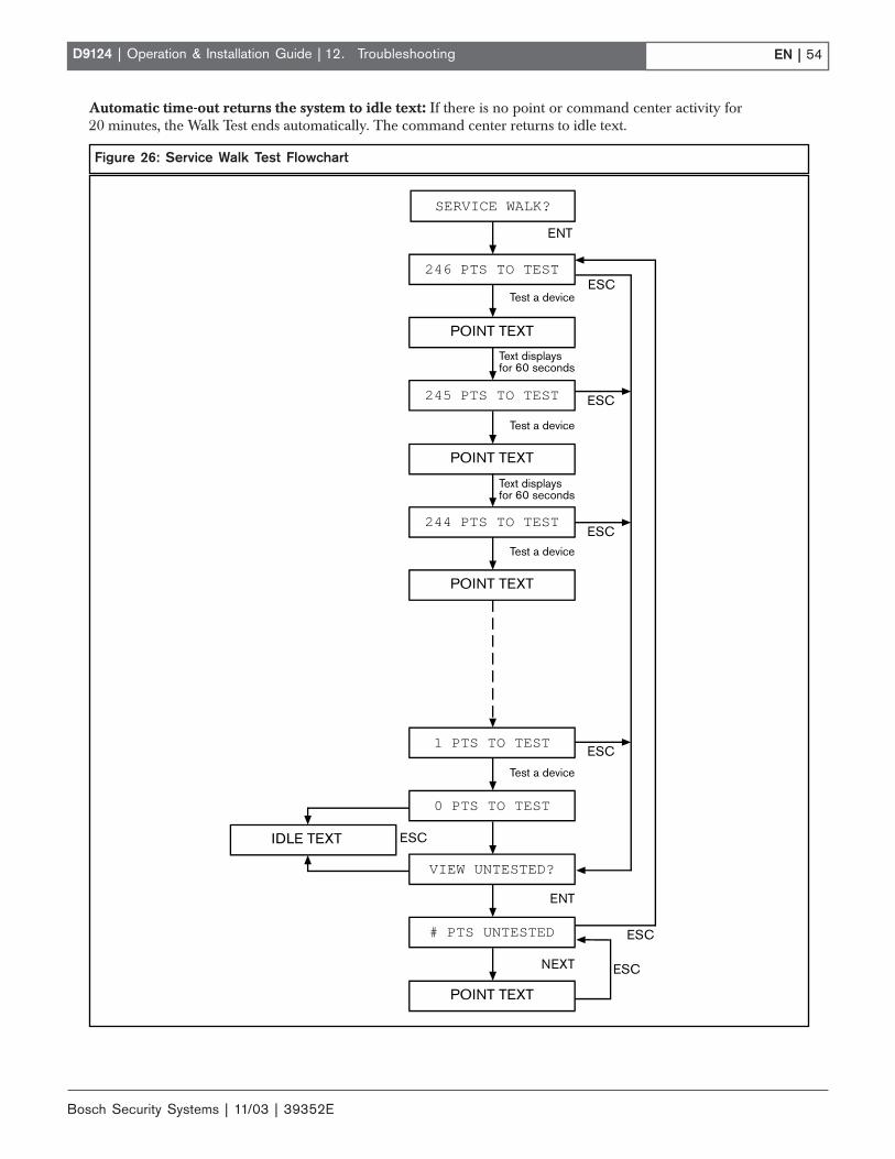
Bosch Security Systems | 11/03 | 39352E
EN | 54D9124 | Operation & Installation Guide | 12. Troubleshooting
Automatic time-out returns the system to idle text: If there is no point or command center activity for20 minutes, the Walk Test ends automatically. The command center returns to idle text.
Figure 26: Service Walk Test Flowchart
SERVICE WALK?
POINT TEXT
246 PTS TO TEST
245 PTS TO TEST
POINT TEXT
244 PTS TO TEST
POINT TEXT
1 PTS TO TEST
IDLE TEXT
0 PTS TO TEST
# PTS UNTESTED
POINT TEXT
VIEW UNTESTED?
NEXT ESC
ENT
ESC
ESC
ESC
Test a device
Test a device
Text displaysfor 60 seconds
ESC
ESC
ESC
Test a device
Text displaysfor 60 seconds
Test a device
ENT

EN | 55D9124 | Operation & Installation Guide |
Bosch Security Systems | 11/03 | 39352E
12.16 Ground FaultIf a D9124 System detects a ground fault, considered ahigh impedance fault to earth ground of approximately100 kΩ or less, the control panel’s command centershows SERVC GND FAULT. Use the followingprocedure as a general guideline in identifying andisolating the cause of the earth ground fault.
Read the following procedure carefullybefore trying to identify the cause of theground fault.
12.16.1 Isolating Earth Ground Faults
Terminals 6 and 7 are not energized.Terminal 8 is energized.
To isolate earth ground faults:
1. With this safety measure in mind, first verify theground fault is, or is not on the battery terminals(Terminals 4 and 5). Use a digital voltmeter (DVM)and a 13-in. jumper wire. As a reference point, whena D9124 Control Panel is not in a ground faultcondition, a voltage reading between Terminals 9and 10 is 6.5 VDC to 6.8 VDC.
2. Place the DVM on a DC volts scale. Connect thepositive (red) lead of the DVM to Terminal 10 (earthground) and negative (black) lead to Terminal 9(common) of the control panel.
Stop if voltage reading is between13.70 VDC and 13.88 VDC.
3. This voltage reading means the ground fault can bein one of the control panel power circuits such as theBattery, or Aux.
Remove both battery wires from Terminals 4 and 5simultaneously. If the voltage across Terminals 9 and10 changes to 6.5 VDC to 6.8 VDC (indicating anormal reading), the ground fault is on the batterywire(s). Locate and remove the ground fault.
4. If the voltage across Terminals 9 and 10 stillmeasures between 13.70 VDC and 13.88 VDC,reconnect the battery wire(s) back to Terminals 4and 5 and go to Step 5.
12. Troubleshooting
Stop if voltage across Terminals 9 and 10reads 0 VDC.
5. This voltage reading indicates the ground fault is onany of the control panels’ common terminals.Remove both battery wires from Terminals 4 and 5.If the voltage across terminals 9 and 10 changes to6.5 VDC to 6.8 VDC, the ground fault is on thisbattery is negative side. Locate and remove theground. If voltage across Terminals 9 and 10 doesnot change, reconnect both battery wires toTerminals 4 and 5 and go to Step 6.
6. With the DVM still connected between Terminals 9and 10, use Table 23 to determine which terminalgrouping has the ground fault.
Terminals 6 and 7 are not energized.Terminal 8 is energized.
7. Once the voltage is determined, remove the wire(s)from the terminals listed and verify the voltage onTerminals 9 and 10 is approximately 6.5 VDC to6.8 VDC. If the voltage does not measure withinthis range after removing the suspected wire,continue to check the remaining wires connected tothe terminal group.
If voltage at Terminals 9and 10 is:
Ground fault is on Terminal:
0 VDC 4, 9, 12, 15, 18, 21, 23(D9412G only), and/or 29, 6and/or 7
approximately 1.7 VDC 6 and/or 7approximately 2.5 VDC 11, 13, 14, 16, 17, 19, 20,
and/or 22,approximately 7.0 VDCfluctuating
30 and/or 31
approximately 7.6 VDCfluctuating
1 and/or 2
approximately 11 VDCto12 VDC
25 (D9412G/D7412G only),26 (D9412G only), and/or 28(see Step 5)
approximately 13.8 VDC 3, 5, 8, 24 (D9412G only),and/or 32
Table 23: Terminal Grouping Ground Fault
Bosch Security Systems | 11/03 | 39352E
EN | 56D9124 | Operation & Installation Guide |
8. Verify the wire removed has an earth ground shortby disconnecting the DVM and switching the DVMto read ohms. Attach the red lead of the DVM to theend of the wire that was removed (making sure theconnection is on the conductor of the wire and notthe jacket). Attach the black lead of the DVM toTerminal 10 of the control panel. If there is an earthground short, the reading can range between 0 kΩand 95 kΩ.
9. Continue troubleshooting the field wiring toeliminate the ground. Begin the process by startingin the middle of the wire run and checking whichside of the wire run has the earth ground short. Aknown earth ground is needed for the test.
10. Once the earth ground fault is isolated, remove theground, repair the wire, or replace the wire.
11. If the voltage reading represents a ground fault onTerminals 25, 26, or 28, the ground fault conditionmight physically be on either the ZONEX bus,POPIT bus, or an input point on an OctoPOPIT orPOPIT.
12. Troubleshooting
To isolate the ground fault in this scenario:
- Disconnect the positive and negative leads to thebattery or batteries.
- Connect the jumper wire from Terminal 10 toTerminal 9 for approximately 5 seconds.
- Points with a ground fault on the input loopchange to an open state while Terminals 9 and 10are shorted. Do not keep the jumper wire onTerminals 9 and 10 for longer than 10 seconds.Only use this procedure to track down groundfault conditions.
12.17 Panel BuzzerBeginning with version 6.3 and higher, the control panelon-board buzzer pulses 1 second on, 1 second off if asupervised command center no longer responds to pollsfrom the control panel. The buzzer is silenced when thesupervised command center begins responding to pollsagain or by pressing [COMMAND 4] from anoperational command center.
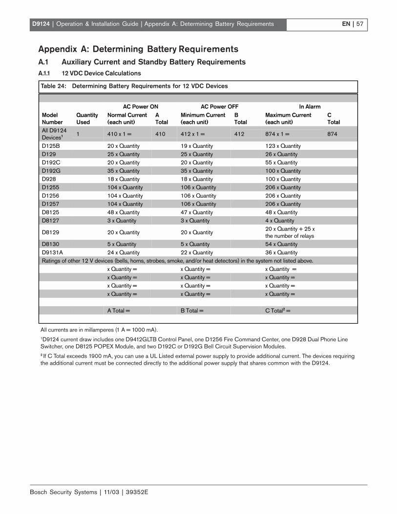
EN | 57D9124 | Operation & Installation Guide |
Bosch Security Systems | 11/03 | 39352E
Appendix A: Determining Battery Requirements
Appendix A: Determining Battery RequirementsA.1 Auxiliary Current and Standby Battery RequirementsA.1.1 12 VDC Device Calculations
Table 24: Determining Battery Requirements for 12 VDC Devices
AC Power ON AC Power OFF In AlarmModelNumber
QuantityUsed
Normal Current(each unit)
ATotal
Minimum Current(each unit)
BTotal
Maximum Current(each unit)
CTotal
All D9124Devices1 1 410 x 1 = 410 412 x 1 = 412 874 x 1 = 874
D125B 20 x Quantity 19 x Quantity 123 x QuantityD129 25 x Quantity 25 x Quantity 26 x QuantityD192C 20 x Quantity 20 x Quantity 55 x QuantityD192G 35 x Quantity 35 x Quantity 100 x QuantityD928 18 x Quantity 18 x Quantity 100 x QuantityD1255 104 x Quantity 106 x Quantity 206 x QuantityD1256 104 x Quantity 106 x Quantity 206 x QuantityD1257 104 x Quantity 106 x Quantity 206 x QuantityD8125 48 x Quantity 47 x Quantity 48 x QuantityD8127 3 x Quantity 3 x Quantity 4 x Quantity
D8129 20 x Quantity 20 x Quantity20 x Quantity + 25 xthe number of relays
D8130 5 x Quantity 5 x Quantity 54 x QuantityD9131A 24 x Quantity 22 x Quantity 36 x QuantityRatings of other 12 V devices (bells, horns, strobes, smoke, and/or heat detectors) in the system not listed above.
x Quantity = x Quantity = x Quantity =x Quantity = x Quantity = x Quantity =x Quantity = x Quantity = x Quantity =x Quantity = x Quantity = x Quantity =
A Total = B Total = C Total2 =
All currents are in millamperes (1 A = 1000 mA).1D9124 current draw includes one D9412GLTB Control Panel, one D1256 Fire Command Center, one D928 Dual Phone LineSwitcher, one D8125 POPEX Module, and two D192C or D192G Bell Circuit Supervision Modules.2 If C Total exceeds 1900 mA, you can use a UL Listed external power supply to provide additional current. The devices requiringthe additional current must be connected directly to the additional power supply that shares common with the D9124.

Bosch Security Systems | 11/03 | 39352E
EN | 58D9124 | Operation & Installation Guide |
A.1.2 24 VDC Device Calculations
A.2 Standby Battery Calculations for FireAlarm Applications
Calculate Standby Battery and AuxiliaryCurrent first. You must calculate totals forcolumns B and C in the appropriate (12 V or24 V devices) chart in Section A.1 AuxiliaryCurrent and Standby Battery Requirementsbefore you can complete the followingcalculations.
A.2.1 Calculations for D9412GLTB and 12 VDCInitiating and Indicating Devices
Central Station or Local Systems (24-Hour Standby)
Central station or local systems require 24 hours ofstandby plus 5 minutes of alarm operation at the end ofthe 24-hour period. A single battery is sometimesadequate for central station systems, but you must installtwo batteries to meet the basic standby requirements fora local system installation. You must use battery amperehour (Ah) calculations to verify compliance. Theformula in Figure 27 includes the calculation for5 minutes of alarm operation at the end of the 24-hourperiod, and a 10% contingency factor allowing for thedepletion of battery capacity with age.
Remote Station or Auxiliary Systems(60-Hour Standby)
Remote station or auxiliary systems require 60 hours ofstandby plus 5 minutes of alarm operation at the end ofthe 60-hour period. A UL Listed power supply withadditional batteries installed in a separate D9109 orD9109G enclosure may be required in the D9124 Systemto meet the basic standby requirements for a remotestation or auxiliary system installation. You must usebattery ampere hour (Ah) calculations to verifycompliance. The formula in Figure 28 includes thecalculation for 5 minutes of alarm operation at the endof the 60-hour period, as well as a 10% contingencyfactor allowing for depletion of battery capacity withage.
Ampere-Hour Calculation Formulas
Use totals from Section A.1.1 Calculations for 12 VDCDevices (currents in millamperes).
The total Ah requirements must not exceed the Ahcapacity of:
Two D126 Batteries = 14 Ah (14000 mAh)
Two D1218 Batteries = 34.4 Ah (34400 mAh) if using17.2 Ah batteries and 36 Ah (36000 mAh) if using 18Ah batteries
Appendix A: Determining Battery Requirements
AC Power ON AC Power OFF In AlarmModelNumber
QuantityUsed
Normal Current(each unit)
ATotal
Minimum Current(each unit)
BTotal
Maximum Current(each unit)
CTotal
(mA x Quantity) (mA x Quantity) (mA x Quantity)x Quantity = x Quantity = x Quantity =x Quantity = x Quantity = x Quantity =x Quantity = x Quantity = x Quantity =x Quantity = x Quantity = x Quantity =x Quantity = x Quantity = x Quantity =x Quantity = x Quantity = x Quantity =x Quantity = x Quantity = x Quantity =x Quantity = x Quantity = x Quantity =
A Total = B Total = C Total* =
Table 25: Determining Battery Requirements for 24 VDC Devices
* C Total must not be greater than 4.0 A (4000 mA).
When connecting two D1218 Batteries tothe control panel, both must have the samecapacity (use two 17.2 Ah batteries or two18 Ah batteries).

EN | 59D9124 | Operation & Installation Guide |
Bosch Security Systems | 11/03 | 39352E
Appendix A: Determining Battery Requirements
A.2.2 Calculating D9142 24 VDC Battery CapacityRequirements for Initiating and IndicatingDevices
Central Stations or Local Systems Require 24 HoursStandby
To determine 24-hour standby battery capacity, first usethe column labeled Column B, AC Power OFF (referto Tables 24 and 25) to calculate the total 24 VDCcurrent required. Next, use the column labeled Current(A) in Table 26 to select the row with the current equal toor larger than your calculated total from the chart,Column B. To the left of this current value is thebattery amp hour rating you need. This value alreadyfactors in a 5-minute bell current of 3 A at the end of the24-hour standby period. If your standby current isgreater than 1 A, subtract the current from the bellcurrent. For example, you require 1.294 A of standbycurrent so you need a 38 Ah battery, which recharges in37 hours. The maximum bell current is (4 A to 1.294 A)= 2.716 A of bell current.
60-Hour StandbyBattery A-Hours Current (A) Recharge Time (Hours)7 0.030 12
12 0.105 12
14 0.135 12
17.2 0.183 14
24 0.286 18
36 0.467 27
38 0.497 29
Table 27: 60-Hour Standby
24-Hour StandbyBattery A-Hours Current (A) Recharge Time (Hours)7 0.136 1012 0.322 1014 0.397 1117.2 0.517 1324 0.771 1836 1.219 3438 1.294 37
Table 26: 24-Hour Standby
Figure 28: Remote Station or Auxiliary Systems Ampere-Hour Calculation Formula
Total B Hours Total C Hours Contingency Total mAh( ____________ x 60) + ( ____________ x .083) + 10% = _________
Remote Stations or Auxiliary Systems Require60 Hours Standby
To determine 60-hour standby battery capacity use thecolumn labeled Column B, AC Power OFF (refer toTables 24 and 25) to calculate the 24 VDC currentrequired. Next, use the column labeled Current (A) inTable 27 and select the row where the current is equal toor larger than your calculated total from the chart,Column B. To the left of this current value is thebattery amp rating you need. This value already factorsin a 5-minute bell current of 3 A at the end of the 60-hour standby period.
Recharge batteries within 48 hours after the fully-charged batteries are subjected to a single dischargecycle.
Figure 27: Central Stations or Local Systems Ampere-Hour Calculation Formula
Total B Hours Total C Hours Contingency Total mAh( ____________ x 24) + ( ____________ x .083) + 10% = _________

Bosch Security Systems | 11/03 | 39352E
EN | 60D9124 | Operation & Installation Guide | Appendix A: Determining Battery Requirements
Notes:

EN | 61D9124 | Operation & Installation Guide |
Bosch Security Systems | 11/03 | 39352E
Appendix B: D91422 24 VDC Power Supply
1 - Supervision relay configuration DIP switch 9 - Auxiliary power outputs
2 - AC power LED (green) 10 - Remote status LED connector3 - Power supply trouble LED (red) 11 - Covered 110 VAC connection4 - Power output status LED (green) 12 - Covered 110 VAC fuse F15 - Control panel output connector 13 - D1601 transformer connector
6 - Switched output selection jumpers 14 - 16.5 VAC 40 VA power to control panel7 - Switched output control 15 - Battery connector8 - Supervision relay output
Figure 29: D9142 Power Supply
1HOT
2NEUT
3GND
2FCUT
1N/O
3NO
4COM
5NC
6+ OUT1
7- OUT
9- OUT 2
8+ OUT 2
NO ACNO AC FUSENO DC
BAT TESTLOW BATT
S1
J3
J7
J8
XFRM
XFRM
J1
Off On J5
15
11
12
13
14
1
2
3
4
5
6
7 8 9 10
Appendix B: D9142 24 VDCPower Supply
B.1 D9142 Default Setting FeaturesB.1.1 Description
The D9142 is a supervised, 4 A, 24 V power supply thatcharges standby batteries and supplies power to auxiliarydevices.
The D9142 connects to a dedicated circuit breaker. The120 VAC input terminals on the D9142 are covered foradded safety. The D1601 transformer is fused with athermal non-resettable fuse. The transformer plugs intothe D9142 using an input/output cable and provides ACpower for the D9142 and a 16.5 VAC 40 VA output forpowering the control panel.
D9142 supervises all stages of power for detection incase of a fault.
You can select which trouble events activate asupervision relay output. The relay output allows for aremote indicator of general trouble with the D9142 ACpower, battery, or power output.
Battery Supervision
The D9142 offers low battery and missing batterysupervision for both batteries.
When the battery drops between 22 VDC and 24 VDCor the battery is disconnected, the red Low Battery LEDlights and the power supply triggers the Trouble Relayoutput.
When battery voltage returns between 24.2 VDC and26.5 VDC, the Low battery LED turns off. The D9142resets the Low Battery Trouble output.
D9142 Status LEDs
The LEDs on the left side of the D9142 (Figure 29)indicate the:
• green LED lights when AC power is connected andapplied to the D9142. Normally, this LED is on.
• red Power Supply Trouble LED lights when D9142senses trouble. Normally, this LED is off.
• green Power Output Status LED lights when poweroutput is powered on. The LED turns off when theoutput power is off.

Bosch Security Systems | 11/03 | 39352E
EN | 62D9124 | Operation & Installation Guide | Appendix B: D9142 24 VDC Power Supply
Table 28: D9124 24 V Power Supply Specifications
Power Input Nominal: 120 VAC, 60 Hz, 360 VAPower Outputs 24 V indicating and initiating devices with a minimum operating voltage greater than 18.9 VDC
or a maximum operating voltage less than 28 VDC can be damaged or fail to operate.One Output: 4 A maximumDC Output Voltage (AC applied): 22 VDC minimum, 28 VDC maximumDC Output Voltage (No AC): 18.9 VDC minimum, 27 VDC maximum
Low BatteryVoltage
Trouble Threshold: 22 VDC minimum, 24.1 VDC maximumRestoral Threshold: 24.2 VDC minimum, 26.5 VDC maximum
Load Shed Voltage Trouble Threshold: 18.9 VDC minimum, 20.5 VDC maximumVoltage Restoral Threshold: 23.1 VDC minimum, 24.7 VDC maximum
AC Line Fuse F1 Type 3 AG: 4 A, 250 V Slow Blow. Bosch Security Systems (P/N: 57-01338-004)SupervisionOutput Relay
Form C, rated for 2 A @ 12 or 24 VDC
EnvironmentalConsiderations
Operating Temperature: 0°C to +50°C (+32°F to +122°F)Relative Humidity: 5% to 85% at +30°C (+86°F) non-condensing
Batteries Use the following 12 V sealed lead/acid batteries: 7 Ah, 12 Ah, 14 Ah, 17.2 Ah, 24 Ah, 36 Ah,or 38 Ah
B.1.2 Default Trouble Output Settings
Five trouble conditions can activate the relay. See theSupervision Relay Configuration DIP Switch (S1) on theD9142 (Figure 29).
NO AC: 120 VAC power failure annunciation. Do notuse for 24 V fire applications. The D9124 Control Panelprovides this function.
NO AC FUSE: Fuse F1 failure.
NO DC: Power output failure due to grounds or shortson the output circuit.
BATT TEST: Causes fault if battery test circuit fails.
LOW BATTERY: Battery voltage low or batterymissing.
The factory settings are shown in Figure 30.
B.1.3 Specifications
Figure 30: D9142 Factory Switch Settings
ON OFF
NO AC
NO AC FUSE
NO DCBATT TESTLOW BATT
S1

EN | 63D9124 | Operation & Installation Guide |
Bosch Security Systems | 11/03 | 39352E
Notes:

Bosch Security Systems130 Perinton ParkwayFairport, NY 14450-9199 USAwww.boschsecurity.usCustomer Service: (800) 289-0096Technical Support: (888) 886-6189
© 2003 Bosch Security Systems39352E