3920 iDOME INSTALLATION AND OPERATION COHU, INC ...
38
6X-1026E 1 Installation and Operation Manual COHU, INC. ELECTRONICS DIVISION 3920 SERIES iDOME CAMERA/POSITIONER SYSTEM Figure 1. iDome www.cohu-cameras.com [email protected] June 21, 2012 Technical Manual 6X-1026E www.cohu-cameras.com/content/contactus
Transcript of 3920 iDOME INSTALLATION AND OPERATION COHU, INC ...
6X-1026E 1
INSTALLATION AND OPERATION
3920 iDOME
Installation and Operation ManualCOHU, INC. ELECTRONICS DIVISION
3920 SERIESiDOME CAMERA/POSITIONER SYSTEM
Figure 1. iDome
www.cohu-cameras.com
June 21, 2012Technical Manual 6X-1026E
www.cohu-cameras.com/content/contactus

6X-1026E2
INSTALLATION AND OPERATION 3920 iDOME
TABLEOF CONTENTS
LIST OF TABLES
LIST OF FIGURES
FIG. TITLE PAGE
1 iDome 1
2 Model Number Interpretation Diagram 4
3 Dimensions, 3920 5
4 Basic Mounting Configurations 6
5 Model 8540B Test Stand 7
6 Type CTC-29 Cable, Test/ Setup, Wiring Diagram 8
7 Typical RS-232 to RS-422 Converter 8
8 Type CTC-33 Cable, 9200 Control Panel Connection 9
9 Quick Disconnect Assemby 10
10 Wall Mount Arm 10
11 Arm Dimensions 11
12 Typical Pole Mount 12
13 iDome Quick Disconnect Mounting 13
14 Strap Wrench 14
15 Pole Mount Dimensions 14
16 Mast Arm Mount 14
17 Intreconnection Diagram, iDome to Local Control Panel 15
18 Interconnection Diagram, iDome to Equipment Cabinet 16
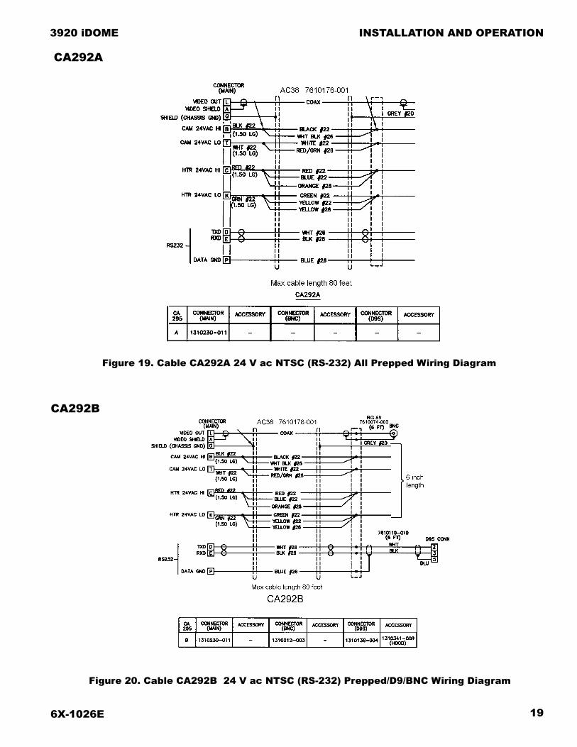
19 Cable CA-292A 24 Vac (RS-232) All Prepped Leads 19
20 Cable CA-292B 24 Vac (RS-232) Prepped/D9/BNC 19
21 Cable CA-293A 24 Vac (RS-422) All Prepped Leads 20
22 Cable CA-293B 24 Vac (RS-232) Prepped/D9/BNC 20
23 Cable CA-293M 115 Vac (RS-422) RJ-45/Prepped/BNC 21
24 Cable CA-295E 115 V ac (RS-422), All Prepped Leads 22
25 Cable CA-295F 115 Vac (RS-422) Plug, Prepped, BNC 22
26 Cable CA-295G 115 Vac (RS-422) Plug, 422-232, BNC 23
27 Cable CA-295H 115 Vac (RS-232) Single AMP Connector 23
28 Cable CA-295M 115 Vac (RS-232) Plug, RJ45, BNC 24
29 Cable CA-296A 115 V ac (RS-232), All Prepped Leads 25
30 Cable CA-296B 115 Vac (RS-232) Plug, Prepped, BNC 25
31 Cable CA-296C 115 Vac (RS-422) Plug, D9F, BNC 26
32 iDome Pin Layout and Functions 27
33 Typical About WinMPC Screen 29
34 Typical WinMPC Main Screen 29
35 Typical WinMPC Communications Setup Screen 30
36 iDome Maintenance Features 33
SECTION TITLE PAGE
1.0 GENERAL DESCRIPTION 3
1.1 Electrical Characteristics 3
1.2 Mechanical Characteristics 4
2.0 INSTALLATION 5
2.1 Installation Introduction 6
2.2 Equipment Supplied 9
2.3 Equipment Required But Not Supplied 12
2.4 Power Requirements 13
2.5 Pendant Mount Installation 16
2.6 Wall Mount Installation 16
2.7 Pole Mount Installation 17
2.8 Alternate Mounting Methods 17
2.9 Testing Cables 16
2.10 System Cabling Requirements 17
2.11 GUI Interface 26
3.0 OPERATION 30
3.1 Local Panel Control 30
3.2 Local Laptop PC Control 31
4.0 MAINTENANCE 31
4.1 Preventive Maintenance 31
5.0 SHIPPING AND STATIC DIS-CHARGE CONSIDERATIONS 32
5.1 Unpacking & Receiving Inspection 32
5.2 Preparation for Shipment & Storage 32
5.3 Static Discharge Protection 32
TABLE TITLE PAGE
1 Basic Mounting Arrangements 5
2 Required Cable Characteristics 14
3 Common System Cables Used 18
4 iDome Connector Functions 28
5 Communications Settings 28
6 Specifications 34

6X-1026E 3
INSTALLATION AND OPERATION
3920 iDOME
NOTE: This equipment has been tested and found to comply with the limits for a Class A Digital Device, pursuant to Part 15 of the FCC Rules. These limits are designed to provide reasonable protection against harmful interference when the equipment is operated in a commercial environment. This equipment generates, uses, and can radiate radio frequency energy and, if not installed and used in accordance with the instruction manual, may cause harmful interference to radio communica-tions. Operation of this equipment in a residential area is likely to cause harmful interference in which case the user will be required to correct the interferecne at his own expense.
CAUTION: Changes or modifications to this device not expressly approved by Cohu Electronics could void the user’s authority to operate the device.
This device complies with Part 15 of the FCC Rules. Operation is subjected to the following two conditions: (1) this device may not cause harmful interference and (2) this device must accept any interference received, including interference that may cause undesired operation.
1.0 GENERAL DESCRIPTION
The iDome series is an integrated camera/posi-tioner unit that integrates a high performance digital signal processing camera, pan-and-tilt, and control receiver for communications into one integrated package (figure 1).
Throughout this manual the entire assembly will typically be referred to as the “iDome.”
Specifications are contained in table 6 at the end of this manual and a model number interpretation diagram is provided in figure 2. This diagram can be used to interpret an existing model number. An iDome can be operated via either RS-232 or RS-422 communications depending on which pins of the connector are used. Thus there is no model number designation to reflect a choice for the com-munications mode.
WARNING
Two versions of the iDome operate from volt-ages that can be dangerous: model 3925 (115 V ac) and model 3923 (230 V ac). Use all appropriate care when installing and main-taining either of these versions of the iDome.
1.1 ELECTRICAL CHARACTERISTICS
The camera uses digital signal processing. It has an internal source ID generator. Integration control plus a built-in video storage card provides full color continuous video even at very low light levels.
The iDome speeds are variable with maximums of 250° per second for pan and tilt. Pan range is
a continuous 360 degrees while the tilt range is 0 to 90 degrees from the horizontal with auto-flip at the 90° point. There are 64 preset positions with a preset accuracy of 0.1 degree. When responding to standard pan-preset or manual control, the iDome can move with a pan speed of 250° per second.
This iDome will operate in temperature ranges from -34° to +74° C and with winds of up to 90 mph. The enclosure protects against salt, grime, dirt, and moisture.
The integrated receiver/driver, contained within the iDome, communicates using Cohu protocol mes-sages and will also control the digital DSP camera functions. All iDome functions are operable via either RS-232 or RS-422 serial communications.
The iDome is fully compatible with existing Cohu controllers. In case of power failure, all 64 preset positions are stored in nonvolatile memory.
Each iDome “address” within a surveillance sys-tem can be selected electronically from the Monitor-ing Center. There are no mechanical dip switches to set at the camera, and each unit responds to the central command only if addressed. This provides greater integration flexibility for the designer and more dynamic camera control for the operator
1.1.1 Control Software
WinMPCWinMPC Graphical User Interface (GUI) software
is available for setting the address and performing field tests when connected to a single camera. (It cannot be used to control more than one camera at

6X-1026E4
INSTALLATION AND OPERATION 3920 iDOME
Figure 2. Model Number Interpretation Diagram
MODEL NUMBER INTERPRETATION DIAGRAM
4 24 Vac5 115 Vac
5 NTSC 35X Day/Night EIS7 PAL Phase Adjust Line Lock8 PAL 35X Day/Night EIS
1 Cohu Protocol American Dynamics Pelco D Ultrak Vicon Javelin Kalatel Philips / Bosch2 NTCIP Protocol
0 Clear1 Smoked
PENDPOLEWALL
DSP color/mono 1/4 inchprogressive scan domecamera with zoom lens
Low Pressure IndicatorHeatersVariable Speed360° pan
Typical ProtocolSelections
EIS is Electronic Image Stabilization
392× — × × 0 × — ××××
POWER
SERIES
VIDEO
PROTOCOL
FEATURES
DOME
MOUNT
a time.) The WinMPC software can be obtained at no cost from either the Cohu-Cameras.com web site or by mail on CD.
CAMS
The CAMS software is intended for controlling multi-iDome systems when the Cohu MPC Master Control Panel is the central control “intelligence” for the system. All control and response commands among the various equipment in the system pass through the Master Control Panel.
NetCAMS
The NetCAMS software is intended for controlling multi-iDome systems when a Windows based PC is the central control “intelligence” for the system. All control and response commands among the vari-ous equipment in the system pass through the Net Cams Server.
1.2 MECHANICAL CHARACTERISTICS
Although the iDome is a single mechanical assem-bly for installation purposes, it actually consists of
two primary subassemblies inside the dome: (1) the camera and (2) the positioner.
All camera circuits are contained within a sealed and pressurized environmental dome housing having either a clear or a smoked window through which the camera lens views outside scenes.
This dome is fully covered by a sun shield spaced slightly away from the housing itself. This minimizes heat buildup due to sunlight. Vent holes at the top of the dome must be kept clear to maintain air flow. Figure 3 gives dimensions of the iDome.
The iDome is a sealed and pressurized (dry nitro-gen) unit intended for indoor or outdoor use under rain, snow, and other typical harsh weather condi-tions.
Communications circuits contained within the iDome are also protected from outdoor weather conditions.
A sealing type MS connector is used on the hous-ing and when mated with a similar MS type cable connector a good environmental seal is provided for the mating pins and sockets.

6X-1026E 5
INSTALLATION AND OPERATION
3920 iDOME
Figure 3. Dimensions, 3920 iDome
A single multiconductor cable is routed to the iDome location and then passed through the mount-ing pendant to provide for all signal, video, and op-erating power connections. Pin functions and layout are shown in figure 32.
2.0 INSTALLATION
This section of the manual provides general instructions about installation of the iDome using various mounting arrangements.
The actual installation should be performed by a qualified installation professional familiar with all the local requirements for proper installation.
Table 1. Basic Mounting Arrangements
MOUNTCONFIG. iDOME ARM POLE
BRACKET
Pendant •Wall • •Pole • • •
NOTE: Dot ( • ) designates items supplied for each mounting configuration.
6X-1026E6
INSTALLATION AND OPERATION 3920 iDOME
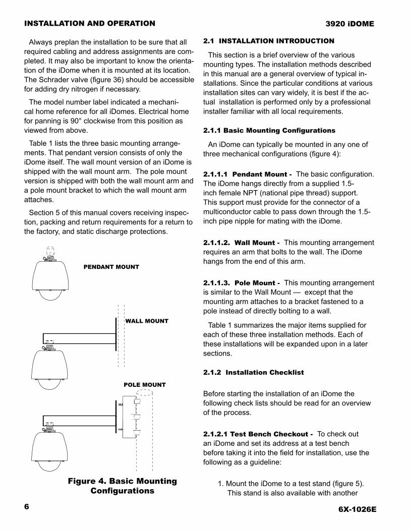
Figure 4. Basic Mounting Configurations
Always preplan the installation to be sure that all required cabling and address assignments are com-pleted. It may also be important to know the orienta-tion of the iDome when it is mounted at its location. The Schrader valve (figure 36) should be accessible for adding dry nitrogen if necessary.
The model number label indicated a mechani-cal home reference for all iDomes. Electrical home for panning is 90° clockwise from this position as viewed from above.
Table 1 lists the three basic mounting arrange-ments. That pendant version consists of only the iDome itself. The wall mount version of an iDome is shipped with the wall mount arm. The pole mount version is shipped with both the wall mount arm and a pole mount bracket to which the wall mount arm attaches.
Section 5 of this manual covers receiving inspec-tion, packing and return requirements for a return to the factory, and static discharge protections.
2.1 INSTALLATION INTRODUCTION
This section is a brief overview of the various mounting types. The installation methods described in this manual are a general overview of typical in-stallations. Since the particular conditions at various installation sites can vary widely, it is best if the ac-tual installation is performed only by a professional installer familiar with all local requirements.
2.1.1 Basic Mounting Configurations
An iDome can typically be mounted in any one of three mechanical configurations (figure 4):
2.1.1.1 Pendant Mount - The basic configuration. The iDome hangs directly from a supplied 1.5-inch female NPT (national pipe thread) support. This support must provide for the connector of a multiconductor cable to pass down through the 1.5-inch pipe nipple for mating with the iDome.
2.1.1.2. Wall Mount - This mounting arrangement requires an arm that bolts to the wall. The iDome hangs from the end of this arm.
2.1.1.3. Pole Mount - This mounting arrangement is similar to the Wall Mount — except that the mounting arm attaches to a bracket fastened to a pole instead of directly bolting to a wall.
Table 1 summarizes the major items supplied for each of these three installation methods. Each of these installations will be expanded upon in a later sections.
2.1.2 Installation Checklist
Before starting the installation of an iDome the following check lists should be read for an overview of the process.
2.1.2.1 Test Bench Checkout - To check out an iDome and set its address at a test bench before taking it into the field for installation, use the following as a guideline:
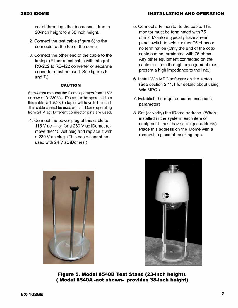
1. Mount the iDome to a test stand (figure 5). This stand is also available with another
PENDANT MOUNT
WALL MOUNT
POLE MOUNT
6X-1026E 7
INSTALLATION AND OPERATION
3920 iDOME
set of three legs that increases it from a 20-inch height to a 38 inch height.
2. Connect the test cable (figure 6) to the connector at the top of the dome
3. Connect the other end of the cable to the laptop. (Either a test cable with integral RS-232 to RS-422 converter or separate converter must be used. See figures 6 and 7.)
CAUTION
Step 4 assumes that the iDome operates from 115 V ac power. If a 230 V ac iDome is to be operated from this cable, a 115/230 adapter will have to be used. This cable cannot be used with an iDome operating from 24 V ac. Different connector pins are used.
4. Connect the power plug of this cable to 115 V ac — or for a 230 V ac iDome, re-move the115 volt plug and replace it with a 230 V ac plug. (This cable cannot be used with 24 V ac iDomes.)
5. Connect a tv monitor to the cable. This monitor must be terminated with 75 ohms. Monitors typically have a rear panel switch to select either 75 ohms or no termination (Only the end of the coax cable can be terminated with 75 ohms. Any other equipment connected on the cable in a loop-through arrangement must present a high impedance to the line.)
6. Install Win MPC software on the laptop. (See section 2.11.1 for details about using Win MPC.)
7. Establish the required communications parameters
8. Set (or verify) the iDome address (When installed in the system, each item of equipment must have a unique address). Place this address on the iDome with a removable piece of masking tape.
Figure 5. Model 8540B Test Stand (23-inch height). ( Model 8540A -not shown- provides 38-inch height)
6X-1026E8
INSTALLATION AND OPERATION 3920 iDOME
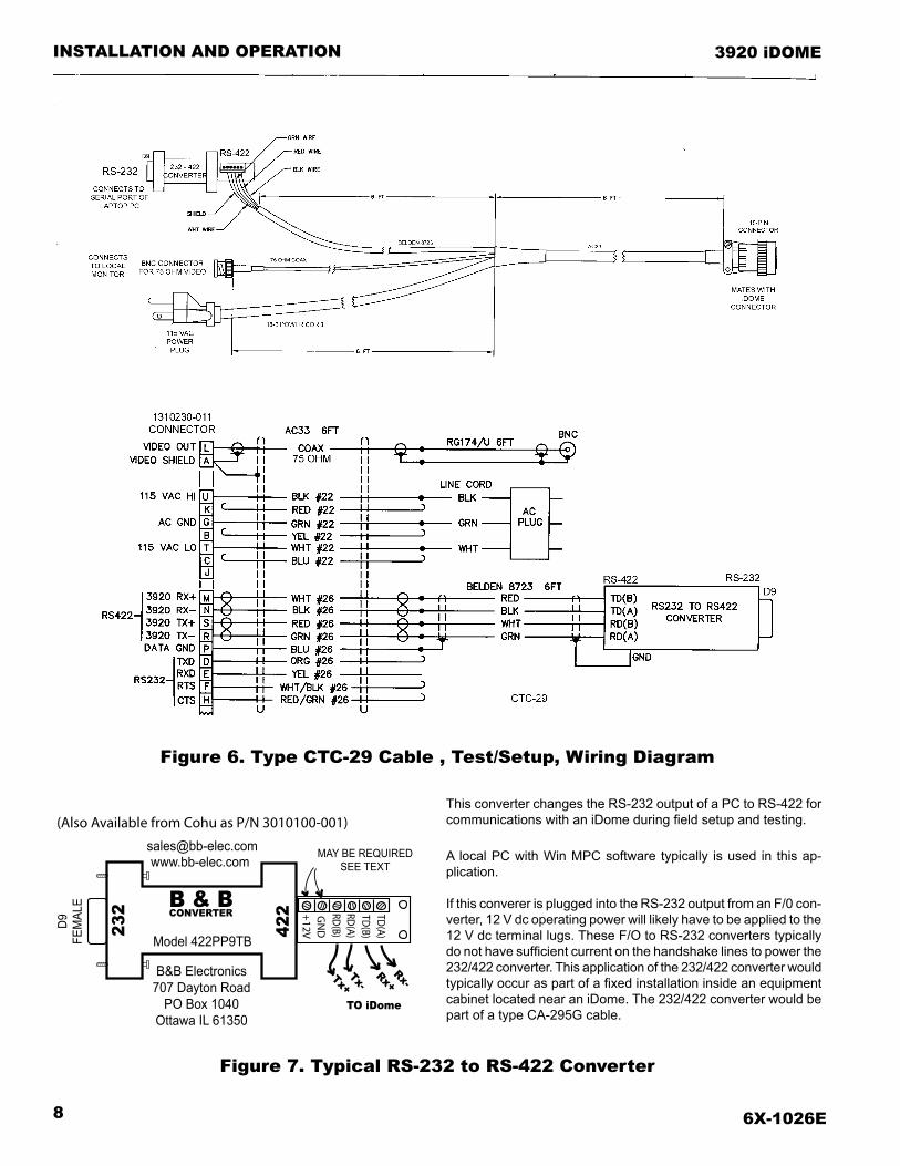
Figure 6. Type CTC-29 Cable , Test/Setup, Wiring Diagram
Figure 7. Typical RS-232 to RS-422 Converter
This converter changes the RS-232 output of a PC to RS-422 for communications with an iDome during field setup and testing.
A local PC with Win MPC software typically is used in this ap-plication.
If this converer is plugged into the RS-232 output from an F/0 con-verter, 12 V dc operating power will likely have to be applied to the 12 V dc terminal lugs. These F/O to RS-232 converters typically do not have sufficient current on the handshake lines to power the 232/422 converter. This application of the 232/422 converter would typically occur as part of a fixed installation inside an equipment cabinet located near an iDome. The 232/422 converter would be part of a type CA-295G cable.
232
D9FE
MAL
E B & B
Model 422PP9TB
B&B Electronics707 Dayton Road
PO Box 1040Ottawa IL 61350
+12VG
ND
RD(B)
RD(A)
TD(A)
TD(B)42
2CONVERTER
(Also Available from Cohu as P/N 3010100-001)
Rx-Rx+Tx+
Tx-
TO iDome
MAY BE REQUIREDSEE TEXT

6X-1026E 9
INSTALLATION AND OPERATION
3920 iDOME
Figure 8. Type CTC-33 Cable , 9200 Control Panel Connection, Test/Setup, Wiring Diagram
9. Verify proper operation of all the various functions controllable through the Win MPC menus.
10. Release the iDome for field installation after it has been determined all functions are working.
2.1.2.2. Field Installation Procedure - Use the following outline to become familiar with the steps required to install an iDome at its field location:
1. Route the cable to the mounting location of the iDome.
2. Route the cable through any mounting arms or brackets.
3. Remove the safety strap from the iDome quick disconnect fastener
4. Thread the nipple portion of the quick dis-connect into the mounting bracket or arm.
5. Route the cable down through this nipple and attach it to the iDome connector
6. Wrap the connector with self sealing waterproofing tape to ensure a long-term trouble free installation.
7. Attach the dome half of the quick discon-nect to the half mounted to the arm or other bracket. (If a particular orientation is required be sure to mount it correctly positioned.)
8. Attach the safety strap back to the other half of the quick disconnect.
9. Connect the laptop to the iDome at the junction box or equipment cabinet.
10. Verity (or set) the address and check all operations.
11. Release the iDome for service.
2.2 EQUIPMENT SUPPLIED
Depending on the mounting configuration, several variations of equipment can be supplied. Refer to table 1 for a list of the basic differences between models as they relate to mounting arrangements.

6X-1026E10
INSTALLATION AND OPERATION 3920 iDOME
Figure 9. Quick Disconnect Assembly
Figure 10. Wall Mount Arm
ARM
WALL
Route systemcable throughhole in wall
into Arm
Use weather-tight gasketbetween Arm and wall
1.5 NPTfor dome
quick disconnectadapter
6X-1026E 11
INSTALLATION AND OPERATION
3920 iDOME
2.2.1 PEND (Pendant Mount). See figure 9.
Pendant mounting is the most basic of the three mounting arrangements. The top half of a quick-dis-connect assembly is threaded into a site supplied 1.5-inch NPT mount.
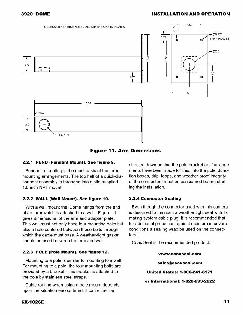
2.2.2 WALL (Wall Mount). See figure 10.
With a wall mount the iDome hangs from the end of an arm which is attached to a wall. Figure 11 gives dimensions of the arm and adapter plate. This wall must not only have four mounting bolts but also a hole centered between these bolts through which the cable must pass. A weather-tight gasket should be used between the arm and wall.
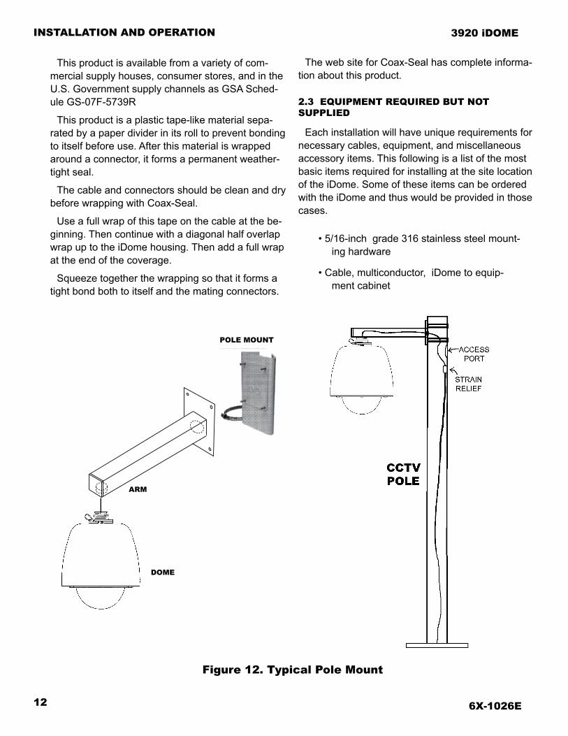
2.2.3 POLE (Pole Mount). See figure 12.
Mounting to a pole is similar to mounting to a wall. For mounting to a pole, the four mounting bolts are provided by a bracket. This bracket is attached to the pole by stainless steel straps.
Cable routing when using a pole mount depends upon the situation encountered. It can either be
directed down behind the pole bracket or, if arrange-ments have been made for this, into the pole. Junc-tion boxes, drip loops, and weather proof integrity of the connectors must be considered before start-ing the installation.
2.2.4 Connector Sealing
Even though the connector used with this camera is designed to maintain a weather tight seal with its mating system cable plug, it is recommended that for additional protection against moisture in severe conditions a sealing wrap be used on the connec-tors.
Coax Seal is the recommended product:
www.coaxseal.com
United States: 1-800-241-8171
or International: 1-828-293-2222
Figure 11. Arm Dimensions
O2.0
O0.375
(TYP 4 PLACES)
4.50
0.75
0.75
6.508.0
1.75
6.0
1.5 NPT
1.75
2.0
17.75
3.0
UNLESS OTHERWISE NOTED ALL DIMENSIONS IN INCHES
2.0
6X-1026E12
INSTALLATION AND OPERATION 3920 iDOME
This product is available from a variety of com-mercial supply houses, consumer stores, and in the U.S. Government supply channels as GSA Sched-ule GS-07F-5739R
This product is a plastic tape-like material sepa-rated by a paper divider in its roll to prevent bonding to itself before use. After this material is wrapped around a connector, it forms a permanent weather-tight seal.
The cable and connectors should be clean and dry before wrapping with Coax-Seal.
Use a full wrap of this tape on the cable at the be-ginning. Then continue with a diagonal half overlap wrap up to the iDome housing. Then add a full wrap at the end of the coverage.
Squeeze together the wrapping so that it forms a tight bond both to itself and the mating connectors.
The web site for Coax-Seal has complete informa-tion about this product.
2.3 EQUIPMENT REQUIRED BUT NOT SUPPLIED
Each installation will have unique requirements for necessary cables, equipment, and miscellaneous accessory items. This following is a list of the most basic items required for installing at the site location of the iDome. Some of these items can be ordered with the iDome and thus would be provided in those cases.
• 5/16-inch grade 316 stainless steel mount-ing hardware
• Cable, multiconductor, iDome to equip-ment cabinet
Figure 12. Typical Pole Mount
ARM
DOME
POLE MOUNT

6X-1026E 13
INSTALLATION AND OPERATION
3920 iDOME
• Connector sealing tape such as Coax Seal
• Junction box or equipment cabinet for sys-tem connections
• Power source
• RS-422 or RS-232 data interconnection as required
• Optional local control panel for mainte-nance and setup purposes
• Fiber optic or other type system intercon-nection
• Cables, at system interconnect cabinet
• Win MPC test and setup GUI
• Operating software for control — such as CAMS or NetCAMS GUI
2.4 POWER REQUIREMENTS
There are three versions of the iDome related to power:
• 115 V ac (Model 3925-xxxx-x)
• 230 V ac (Model 3923-xxxx-x)
• 24 V ac (Model 3924-xxxx-x)
The model number label is attached to the bottom of an iDome. (Electrical home for camera pan is 90° clockwise from this label viewed from above.)
At 120 V ac 60 Hz the iDome heaters draw 72 watts during cold weather when the thermostat has
Figure 13. iDome Quick Disconnect Mounting
Figure 14. Strap Wrench
See section 2.6 and figure 11
SafetyStrap
Sunshield(Camera Below)
Lock Bolt(2)
1.5 NPT Nipple

6X-1026E14
INSTALLATION AND OPERATION 3920 iDOME
Table 2. Required Cable Characteristics
Power for 115 and 230 V ac versions of the iDome use the same connector pins (“U” hot/high and “T” low/neutral). But a camera is never capable of being operated from both of these voltages. It will be wired for either 115 V ac or 230 V ac.
A third version of the Camera is wired for 24 V ac. Pins “B” (high) and “T” (low) are used to provide 24 V ac Camera operating power. If heaters are installed, a separate 24 V ac is applied to pins C (high) and K (low). This input will require that a minimum of 2.7 amps be available (65 watts).
Ac ground for 24 V ac in all cases is pin “G.”
Table 2 lists basic characteristics that are required for a typical multiconductor cable interconnected with the iDome Camera.
It should be noted that RG-59 coaxial cable is avail-able in many different versions with a great variety of characteristics, and many are not suitable for use with video. Always be sure to use RG-59/U with 100 percent copper conductors and at least 95% braid coverage.
The data conductors should be at least 26 gauge twisted pairs. With these data conductors it is desired to minimize capacitance loading and thus only an overall shield should be used — not individual shields over the twisted pairs.
Figure 15. Pole Mount Dimensions
Figure 16. Mast Arm Mount
them turned on. Otherwise power consumption is 27 watts with the stepper motors idle or 50 watts when they are active. Thus the maximum power draw at any one time is 122 watts at 120 V ac.
All electrical connections to and from the iDome are made through a single cable entering at the top.
CONDUCTORFUNCTION CHARACTERISTICS
VIDEO RG-59/U (75 ohm), 100 % copper conductor, 95% minimum braided shield
RS-422 DATA 2 pair, twisted with overall shield, and a data ground wire required. All 26 AWG min
POWER 3-conductor, 22 AWGNote: RS-232 requires only one pair of twisted wires with gnd.

6X-1026E 15
INSTALLATION AND OPERATION
3920 iDOME
Figure 17. Interconnection Diagram, iDome to a Typical Local Control Panel (optional)
FRONT OF TYPICAL LOCAL CONTROL PANEL
The power conductors should be as heavy a gauge as possible. Cohu cables use 22 gauge con-ductors for power. When high quality coaxial cable is being used, these power conductors can become the limiting factor for long cable runs with 115 V ac iDomes (and for the 24 V ac versions).
When the heaters turn on under thermostatic control during low ambient temperatures the voltage
drops at the iDome due to resistance in the wires. This voltage cannot be allowed to drop below the operating requirements of the iDome.
Power wiring of greater sizes reduces this voltage drop when heaters cycle on and off. When design-ing a custom installation it is best to perform a few Ohm’s Law calculations to determine what is the minimum allowable size for power wiring.
115 V ac iDomeoperating withRS-422 data
CABLECA295H
LINKS TOCENTRALCONTROLSTATION
NOTE: THE VIDEO LINEMUST BE TERMINATEDWITH 75 OHMS FOR PROPER OPERATION
NOTE: Use of this panel or a similar type panelis optional. They are used only when on-sitecontrol of an iDome is desired for setupand maintenance operations
115 V acPower
422or 232
6X-1026E16
INSTALLATION AND OPERATION 3920 iDOME
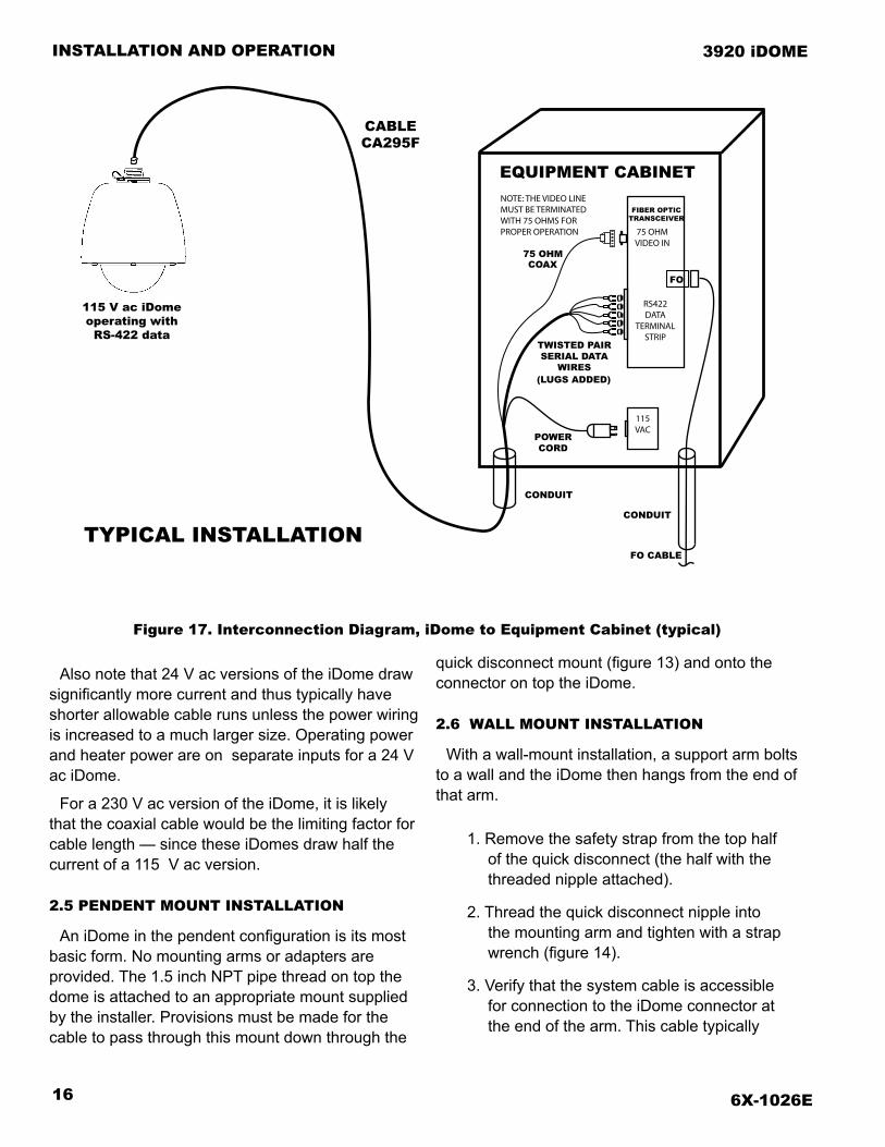
Figure 17. Interconnection Diagram, iDome to Equipment Cabinet (typical)
Also note that 24 V ac versions of the iDome draw significantly more current and thus typically have shorter allowable cable runs unless the power wiring is increased to a much larger size. Operating power and heater power are on separate inputs for a 24 V ac iDome.
For a 230 V ac version of the iDome, it is likely that the coaxial cable would be the limiting factor for cable length — since these iDomes draw half the current of a 115 V ac version.
2.5 PENDENT MOUNT INSTALLATION
An iDome in the pendent configuration is its most basic form. No mounting arms or adapters are provided. The 1.5 inch NPT pipe thread on top the dome is attached to an appropriate mount supplied by the installer. Provisions must be made for the cable to pass through this mount down through the
quick disconnect mount (figure 13) and onto the connector on top the iDome.
2.6 WALL MOUNT INSTALLATION
With a wall-mount installation, a support arm bolts to a wall and the iDome then hangs from the end of that arm.
1. Remove the safety strap from the top half of the quick disconnect (the half with the threaded nipple attached).
2. Thread the quick disconnect nipple into the mounting arm and tighten with a strap wrench (figure 14).
3. Verify that the system cable is accessible for connection to the iDome connector at the end of the arm. This cable typically
TYPICAL INSTALLATIONFO CABLE
POWERCORD
75 OHM
TWISTED PAIRSERIAL DATA
WIRES
NOTE: THE VIDEO LINEMUST BE TERMINATEDWITH 75 OHMS FOR PROPER OPERATION
COAX
115VAC
CABLECA295F
(LUGS ADDED)
FO
115 V ac iDomeoperating with
RS-422 data
CONDUIT
CONDUIT
75 OHMVIDEO IN
RS422DATA
TERMINALSTRIP
FIBER OPTICTRANSCEIVER
EQUIPMENT CABINET
6X-1026E 17
INSTALLATION AND OPERATION
3920 iDOME
must pass through the wall and into the arm.
4. Route the system cable out of the wall and into the back of the wall mount arm. Continue the cable through the arm and out the hole at the iDome mounting loca-tion.
5. Install a weather tight gasket between the arm and the surface of the wall.
6. Bolt the Arm to the wall.
7. Attach the cable plug to the iDome con-nector.
9. Orient the iDome properly and attach it to the other half of the quick disconnect mounted to the arm.
10. Reattach the safety strap.
11. Proceed to section 2.11.5, the checkout procedure.
2.7 POLE MOUNT INSTALLATION
A pole mount installation is similar to the wall mount installation except that the arm fastens to a bracket (figure 15) attached to the pole instead of directly to a wall.
1. Remove the safety strap from the top half of the quick disconnect (the half with the threaded nipple attached).
2. Thread the quick disconnect nipple into the mounting arm and tighten with a strap wrench (figure 14).
3. Verify that the system cable is accessible for connection to the iDome connector at the end of the arm. This cable typically must pass into the back of the pole mount and then into the arm - although various other cable routing configurations are possible.
4. Route the system cable through the mounting and out the hole at the iDome quick disconnect.
5. Provide for weather tight mounting at the pole mount bracket.
6. Bolt the Arm to the bracket.
7. Attach the cable plug to the iDome con-nector.
9. Orient the iDome properly and attach it to the other half of the quick disconnect mounted to the arm.
10. Reattach the safety strap.
11. Proceed to section 2.11.5, the checkout procedure.
2.8 ALTERNATE MOUNTING METHODS
Other mounting configurations are possible. For example, figure 16 shows a mount suitable for at-taching to an arm suspended over a roadway or other location. This mount straps to the arm and is threaded for 1.5 inch NPT mounting. Installing this arm mount requires the use of a strap tensioning tool.
2.9 TESTING CABLES
Two cables are available for test and setup pur-poses:
CTC-29 — A 115 V ac cable for connection to an RS-232 iDome
CTC-33 — A cable intended for use with a Cohu model 9200 control panel.
2.10 SYSTEM CABLING REQUIREMENTS
Table 3 lists typical cables available for use with the iDome. This table summarizes the characteris-tics of each cable. “Prepped” in the table indicates that the wire leads are stripped and pre tinned with solder for attachment to a terminal strip or similar device.
Note that some of these cables are listed for use with 115 V ac ntsc iDomes; however, certain of these 115 V ac cables can be used with a 230 V ac PAL version of the iDome. The 115 and 230 ver-sions of the iDome use the same pins on the con-

6X-1026E18
INSTALLATION AND OPERATION 3920 iDOME
Table 3. Common System Cables Used
nector for application of power. The cable drawings in this manual are noted as for 230 V ac use when this dual purpose cable usage is possible.
Be aware, though, that an iDome is internally wired for either 115 V ac OR 230 V ac — never for both voltages. (And a third version accepts only 24 V ac input power, but on different pins.)
Assembly/wiring diagrams for the cables are shown in figure 19 through figure 31.
A cable connected to the iDome usually routes to equipment in a nearby junction box or equipment cabinet from where another cable continues back to the system control station. Fiber optic cable is often used for this link back to a central location.
Pre-plan all system cabling for an installation. Be-fore an iDome is bolted in place, the cable from the junction box or cabinet must be available to attach to the iDome at its mounting location.
If a 115 V ac iDome is to be operated via its RS-422 pins on the connector then one of the five ver-sions of a type CA-295 cable should be used. These are shown in figures 24 through 28.
If a 115 V ac iDome is to be operated via its RS-232 pins on the connector then one of the three ver-
sions of a type CA-296 cable should be used. These are shown in figures 29 through 31. These cables are limited to a maximum length of 100 foot due to the use of RS-232 data communications over them.
Table 2 lists some basic characteristics required for the conductors in a typical cable.
Table 4 is a pin function list of the iDome connec-tor. This table shows pin U as the line (hot) input for 115 or 230 V ac. An iDome is internally wired for either 115 V ac or 230 V ac. Be sure to know which operating voltage an iDome requires before apply-ing power to a unit.
Also, iDomes operating from 24 V ac use pin B as the “high” input and pin “T” as the low input. Heater power for a 24 V ac iDome connects to pins “C” (high) and “K” (low). Heaters draw 65 watts each time they cycle on in cold weather.
This “high” and “low” designation for 24 V ac does not have the same relevance as it does for proper, safe wiring of 115 and 230 V ac wiring. With 24 V ac the designations serves just as a reference to which wire is being referred to.
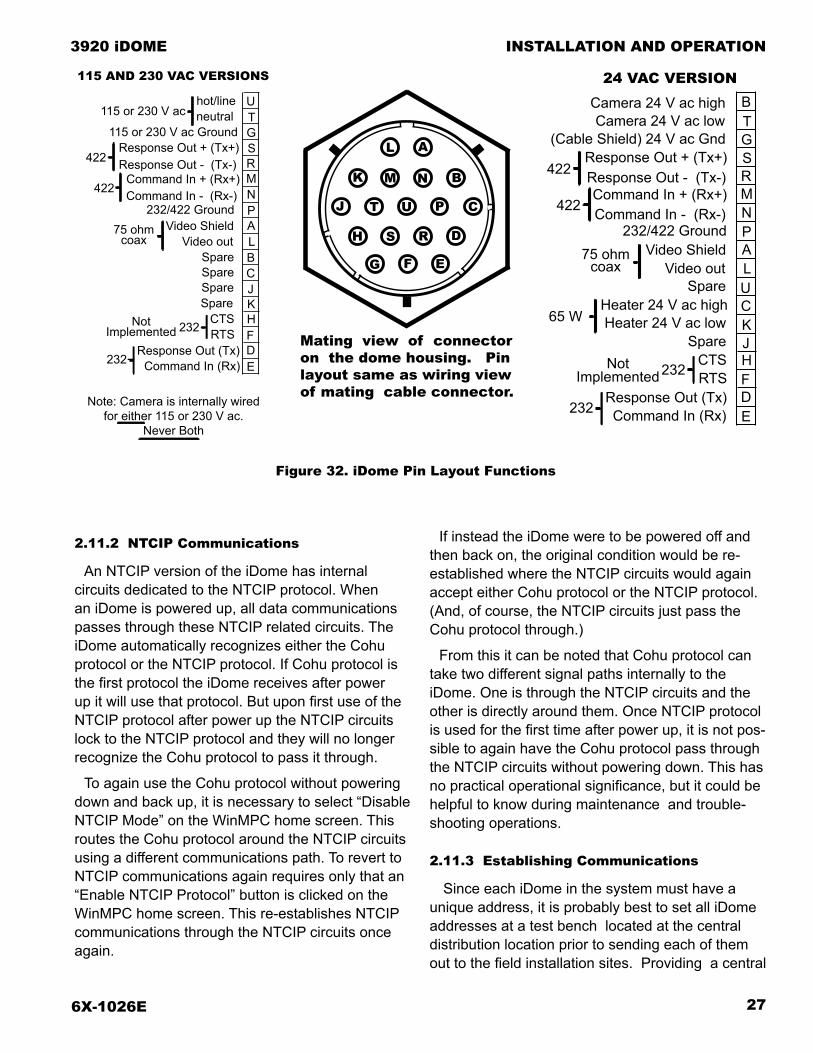
Figure 32 shows pin layout of the iDome connector and gives the function for each of the pins.
Text continued on page 21
Fig. Cable Model
iDomeModel
Basic Characteristic Camera Side Conn.(power/data/video)
System Side Connections
Power Data Video Distance Power Data Video19 CA-292A 3924 24 Vac RS-232 ntsc 80 feet single 18-pin MS style prepped prepped prepped
20 CA-292B 3924 24 Vac RS-232 ntsc 80 feet single 18-pin MS style prepped D9 F BNC
21 CA-293A 3924 24 Vac RS-422 ntsc 80 feet single 18-pin MS style prepped prepped prepped
22 CA-293B 3924 24 Vac RS-422 ntsc 80 feet single 18-pin MS style prepped 432/232 converter BNC
23 CA-293M 3924 24 V ac RS-422 ntsc 80 feed single 18-pin MS style prepped RJ-45 BNC
24 CA-295E 3925 115 Vac RS-422 ntsc 750 feet single 18-pin MS style prepped prepped prepped
25 CA-295F 3925 115 Vac RS-422 ntsc 750 feet single 18-pin MS style plug prepped BNC
26 CA-295G 3925 115 Vac RS-422 ntsc 750 feet single 18-pin MS style plug 422/232 converter BNC
27 CA-295H 3925 115 Vac RS-422 ntsc 750 feet single 18-pin MS style single AMP connector (for use with iControl)
28 CA-295M 3925 115 Vac RS-422 ntsc 750 feet single 18-pin MS style plug RJ-45 (Mavix) BNC
29 CA-296A 3925 115 Vac RS-232 ntsc 100 feet single 18-pin MS style prepped prepped prepped
30 CA-296B 3925 115 Vac RS-232 ntsc 100 feet single 18-pin MS style plug prepped BNC
31 CA-296C 3925 115)) Vac RS-232 ntsc 100 feet single 18-pin MS style plug D9 F BNC
Note: The following cables can also be used with 230 V ac (PAL) cameras: CA295 E, F, G, M and CA296 A, B, C — but any 115 V ac power plug will have to be replaced with a 230 volt plug.
6X-1026E 19
INSTALLATION AND OPERATION
3920 iDOME
Figure 19. Cable CA292A 24 V ac NTSC (RS-232) All Prepped Wiring Diagram
Figure 20. Cable CA292B 24 V ac NTSC (RS-232) Prepped/D9/BNC Wiring Diagram
CA292A
CA292B

6X-1026E20
INSTALLATION AND OPERATION 3920 iDOME
Figure 21. Cable CA293A 24 V ac NTSC (RS-422)All Prepped Wiring Diagram
Figure 22. Cable CA293B 24 V ac NTSC (RS-422) Prepped/422-232/BNC Wiring Diagram
CA293A
CA293B

6X-1026E 21
INSTALLATION AND OPERATION
3920 iDOME
Figure 23. Cable CA293M, Video BNC, 115 V ac Prepped Power Leads, RJ-45 RS-422 Data
CA293M
2.10.1 24 V ac RS-422 Cables
Figure 19 shows cable CA-292A. It is for a nearby iDome that can be used with RS-232 communica-tions. All leads at the system side are stripped and tinned for interconnections with the system equip-ment in a junction box or equipment cabinet.
Figure 20 shows cable CA-292B, also for use when an iDome is to operate with RS-232 com-munications. With this cable, the power leads are stripped and tinned, but a D9 female (socket) connector is attached to the data leads and a BNC connector to the video coax.
Figure 21 (CA-293A) is for RS-422 communica-tions with a 24 V ac iDome. All leads at the system end of the cable are stripped.
Figure 22 (CA-293B) is for use when the sys-tem side of the communications is RS-232 but the iDome must be communicated with using RS-422. This would occur when the iDome was some dis-tance away from the system interconnections where RS-232 was available.
Figure 23 (CA-293M) is for use with system control panels that have an RJ-45 port providing RS-422 communications. The 24 V ac power leads on this cable are stripped wires and the 75 ohm video coax is terminated with a BNC plug. Although this RJ-45 connector is the exact type used with Ethernet, the port provides RS-422.
2.10.2 115 V ac RS-422 Cables
Five cables are available for RS-422 communica-tions with iDomes operating from 115 V ac power. All but one of these cables can also be used with a 230 V ac (PAL) version of the iDome when the power connector is replaced with the proper 230 V ac version.
Cable CA-295H is the exception. It is for use with a model 9300 local control panel that operates only from 115 V ac. This is an optional panel used when local control near an installed iDome is desired.
Text continued on page 24
6X-1026E22
INSTALLATION AND OPERATION 3920 iDOME
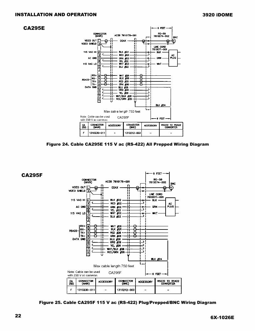
Figure 25. Cable CA295F 115 V ac (RS-422) Plug/Prepped/BNC Wiring Diagram
CA295F
Figure 24. Cable CA295E 115 V ac (RS-422) All Prepped Wiring Diagram
CA295E
6X-1026E 23
INSTALLATION AND OPERATION
3920 iDOME
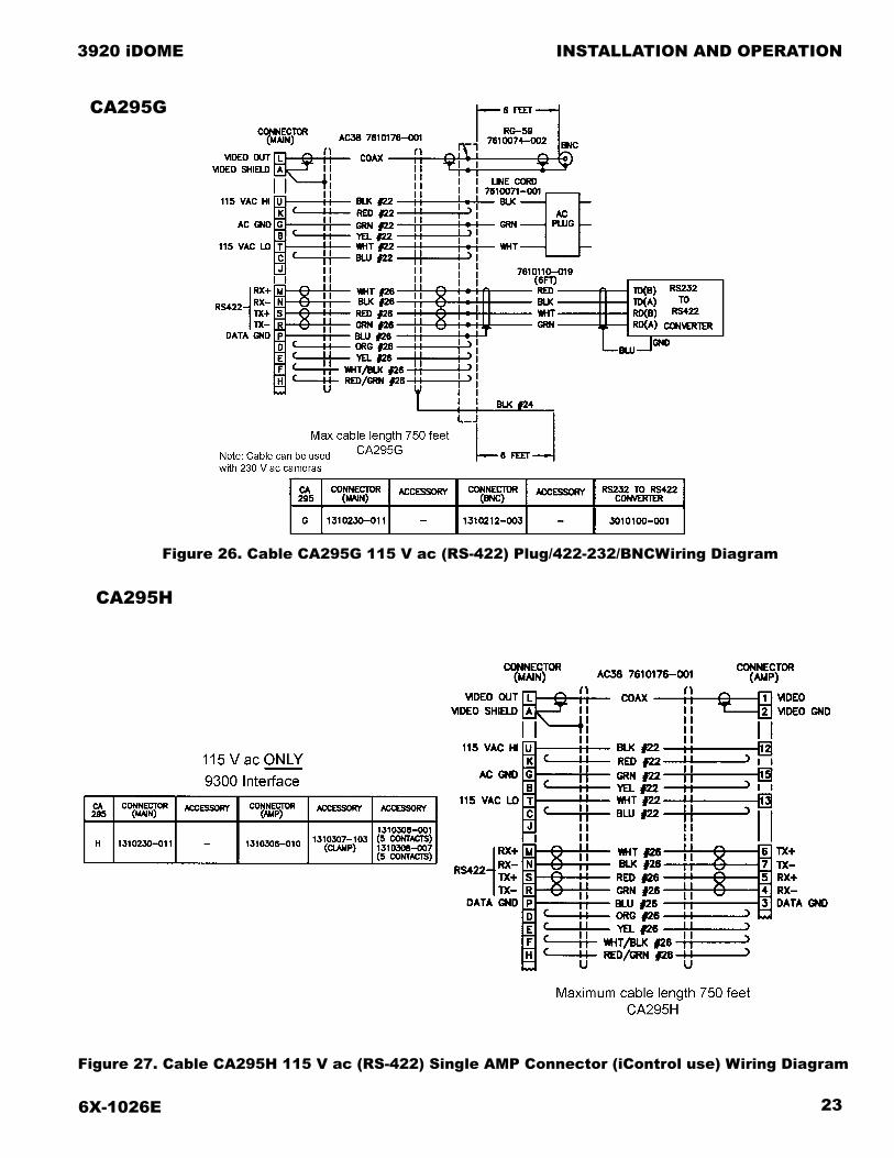
Figure 26. Cable CA295G 115 V ac (RS-422) Plug/422-232/BNCWiring Diagram
Figure 27. Cable CA295H 115 V ac (RS-422) Single AMP Connector (iControl use) Wiring Diagram
CA295G
CA295H

6X-1026E24
INSTALLATION AND OPERATION 3920 iDOME
Figure 28. Cable CA295M 115 V ac (RS-422) Plug/RJ45/(Mavix)/BNC Wiring Diagram
CA295M
Figures 24 through 28 show cables for RS-422 communications.
Figure 24 (CA-295E) has all stripped leads at the system end of the cable
Figure 25 (CA-295F) has a 115 V ac power plug and a BNC connector on the coax. Data leads are stripped. Note that if this cable were to be used with 230 V ac the existing power plug would have to be removed and discarded.
Figure 26 (CA-295G) has a 115 V ac power plug and a BNC connector on the coax. For the data leads, though, it has the RS-422 side of a 232/422 converter connected to them. The RS-232 side of the data converter is for the system interconnections and has a D9 female connector.
Figure 27 (CA-295H) has a single multipin con-nector at the system end of the cable for intercon-nection with a local control panel such as the Cohu model 9300 iControl. This cable is for use only with a 115 V ac iDome.
Figure 28 (CA-295M) has a 115 V ac power plug on the system side, an RJ-45 (Ethernet type) con-nector on the data leads, and a BNC connector on the video coax. The data leads are extended with six feet of CAT-5 cable for the RJ-45 connector.
2.10.3 115 V ac RS-232 Cables (100 foot max)
The following three cables are for cable runs of 100 foot or less. Be aware when planning an instal-lation that the cable run through conduit and other locations may become quite lengthy compared to the physical distance separating an iDome and junction box or equipment cabinet. Verify the actual cable pull length required.
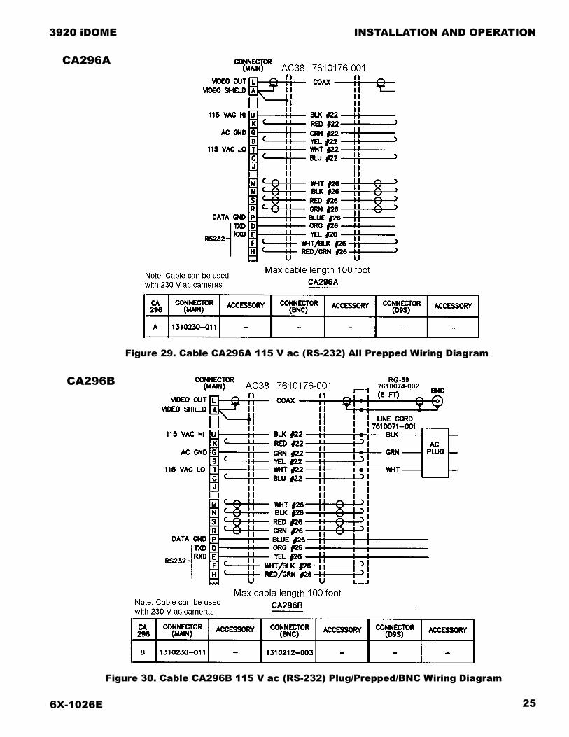
Figure 29 (CA-296A) has power, data, and coax leads stripped and tinned for connections with sys-tem equipment.
Figure 30 (CA-296B) has a 115 V ac power plug and BNC connector on the coax. Data leads are stripped and tinned.
Figure 31 (CA-296C) has a 115 V ac power plug, D9 female on the data leads, and a BNC connector on the coax.
6X-1026E 25
INSTALLATION AND OPERATION
3920 iDOME
Figure 29. Cable CA296A 115 V ac (RS-232) All Prepped Wiring Diagram
CA296A
Figure 30. Cable CA296B 115 V ac (RS-232) Plug/Prepped/BNC Wiring Diagram
CA296B

6X-1026E26
INSTALLATION AND OPERATION 3920 iDOME
Figure 31. Cable CA296C 115 V ac (RS-232) Plug/D9F/BNC Wiring Diagram
CA296C
2.11 GUI INTERFACE
As previously mentioned, several GUI interfaces are available for use with this iDome.
1. Win MPC is used to control a single iDome during installation or maintenance operations. This can be done either at a central shop facility or at the site location of the IDome.
2. CAMS is used to control multiple iDome systems when an MPC Master Control Panel is being used as the central control point.
3. NET Cams is used to control systems with multiple iDome when the central control is a Net Cams Server.
2.11.1 Win MPC Setup
CAUTION
Do not connect WinMPC to more than one iDome (or other addressable equipment) at a time. The address setting function of WinMPC will set the ad-dress of all equipment on a cable TO THE SAME ADDRESS - making the system inoperative.
When WinMPC (figure 33) is used to set up the iDome it must be isolated from all other iDomes in the system. This generally is no problem since the iDome setup is performed either at a test bench location or at the actual iDome site itself. If the ad-dress setting function of WinMPC were to be sent to multiple iDomes they would all have identical addresses programmed into their memory. Since all iDomes (and other addressable equipment) in a system must have a unique address, this would result in an inoperative system.
6X-1026E 27
INSTALLATION AND OPERATION
3920 iDOME
2.11.2 NTCIP Communications
An NTCIP version of the iDome has internal circuits dedicated to the NTCIP protocol. When an iDome is powered up, all data communications passes through these NTCIP related circuits. The iDome automatically recognizes either the Cohu protocol or the NTCIP protocol. If Cohu protocol is the first protocol the iDome receives after power up it will use that protocol. But upon first use of the NTCIP protocol after power up the NTCIP circuits lock to the NTCIP protocol and they will no longer recognize the Cohu protocol to pass it through.
To again use the Cohu protocol without powering down and back up, it is necessary to select “Disable NTCIP Mode” on the WinMPC home screen. This routes the Cohu protocol around the NTCIP circuits using a different communications path. To revert to NTCIP communications again requires only that an “Enable NTCIP Protocol” button is clicked on the WinMPC home screen. This re-establishes NTCIP communications through the NTCIP circuits once again.
Figure 32. iDome Pin Layout Functions
If instead the iDome were to be powered off and then back on, the original condition would be re-established where the NTCIP circuits would again accept either Cohu protocol or the NTCIP protocol. (And, of course, the NTCIP circuits just pass the Cohu protocol through.)
From this it can be noted that Cohu protocol can take two different signal paths internally to the iDome. One is through the NTCIP circuits and the other is directly around them. Once NTCIP protocol is used for the first time after power up, it is not pos-sible to again have the Cohu protocol pass through the NTCIP circuits without powering down. This has no practical operational significance, but it could be helpful to know during maintenance and trouble-shooting operations.
2.11.3 Establishing Communications
Since each iDome in the system must have a unique address, it is probably best to set all iDome addresses at a test bench located at the central distribution location prior to sending each of them out to the field installation sites. Providing a central
SR
BC
D
MN
K
E
FH
G
U
LA
T
JSpareSpare
Response Out + (Tx+)Response Out - (Tx-)
Command In - (Rx-)
Command In (Rx)
Command In + (Rx+)
Spare
232
RTS CTS
115 or 230 V ac Ground
hot/line neutral
SpareVideo out
Video Shield
115 or 230 V ac
422
422
75 ohmcoax
Response Out (Tx)
P232/422 Ground
115 AND 230 VAC VERSIONS
Note: Camera is internally wiredfor either 115 or 230 V ac.
Never Both
NotImplemented 232
SR
B
C
D
MN
K
E
FH
G
ULA
T
J
P
Heater 24 V ac lowSpare
Response Out + (Tx+)Response Out - (Tx-)
Command In - (Rx-)
Command In (Rx)
Command In + (Rx+)
Heater 24 V ac high
232
RTS CTS
(Cable Shield) 24 V ac Gnd
SpareVideo out
Video Shield
Camera 24 V ac low
422
422
75 ohmcoax
Response Out (Tx)
232/422 Ground
Camera 24 V ac high
232
24 VAC VERSION
NotImplemented
65 W
Mating view of connectoron the dome housing. Pinlayout same as wiring viewof mating cable connector.
A
N BMK
L
J T U P C
DRSH
G F E
6X-1026E28
INSTALLATION AND OPERATION 3920 iDOME
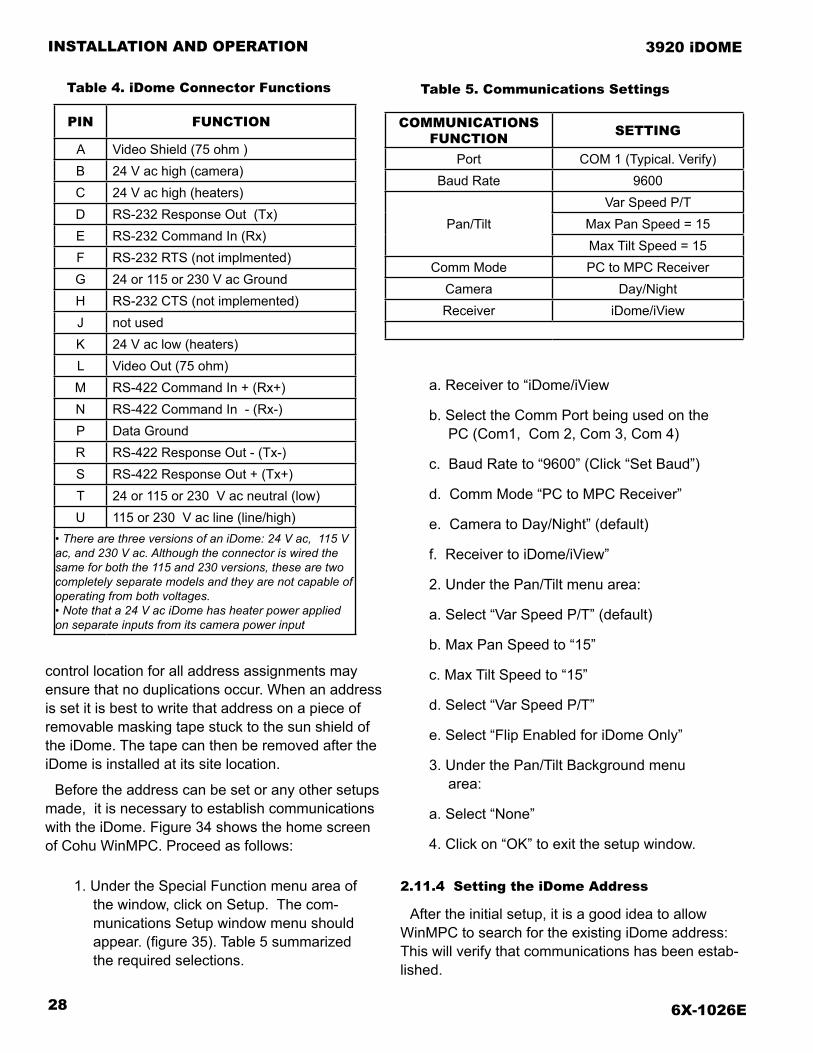
Table 5. Communications SettingsTable 4. iDome Connector Functions
control location for all address assignments may ensure that no duplications occur. When an address is set it is best to write that address on a piece of removable masking tape stuck to the sun shield of the iDome. The tape can then be removed after the iDome is installed at its site location.
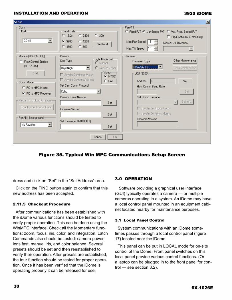
Before the address can be set or any other setups made, it is necessary to establish communications with the iDome. Figure 34 shows the home screen of Cohu WinMPC. Proceed as follows:
1. Under the Special Function menu area of the window, click on Setup. The com-munications Setup window menu should appear. (figure 35). Table 5 summarized the required selections.
a. Receiver to “iDome/iView
b. Select the Comm Port being used on the PC (Com1, Com 2, Com 3, Com 4)
c. Baud Rate to “9600” (Click “Set Baud”)
d. Comm Mode “PC to MPC Receiver”
e. Camera to Day/Night” (default)
f. Receiver to iDome/iView”
2. Under the Pan/Tilt menu area:
a. Select “Var Speed P/T” (default)
b. Max Pan Speed to “15”
c. Max Tilt Speed to “15”
d. Select “Var Speed P/T”
e. Select “Flip Enabled for iDome Only”
3. Under the Pan/Tilt Background menu area:
a. Select “None”
4. Click on “OK” to exit the setup window.
2.11.4 Setting the iDome Address
After the initial setup, it is a good idea to allow WinMPC to search for the existing iDome address: This will verify that communications has been estab-lished.
COMMUNICATIONSFUNCTION SETTING
Port COM 1 (Typical. Verify)Baud Rate 9600
Pan/TiltVar Speed P/T
Max Pan Speed = 15Max Tilt Speed = 15
Comm Mode PC to MPC ReceiverCamera Day/NightReceiver iDome/iView
PIN FUNCTION
A Video Shield (75 ohm )B 24 V ac high (camera)C 24 V ac high (heaters)D RS-232 Response Out (Tx)E RS-232 Command In (Rx)F RS-232 RTS (not implmented)G 24 or 115 or 230 V ac GroundH RS-232 CTS (not implemented)J not usedK 24 V ac low (heaters)L Video Out (75 ohm)M RS-422 Command In + (Rx+)N RS-422 Command In - (Rx-)P Data GroundR RS-422 Response Out - (Tx-)S RS-422 Response Out + (Tx+)T 24 or 115 or 230 V ac neutral (low)U 115 or 230 V ac line (line/high)
• There are three versions of an iDome: 24 V ac, 115 V ac, and 230 V ac. Although the connector is wired the same for both the 115 and 230 versions, these are two completely separate models and they are not capable of operating from both voltages.• Note that a 24 V ac iDome has heater power applied on separate inputs from its camera power input

6X-1026E 29
INSTALLATION AND OPERATION
3920 iDOME
Figure 33. Typical About WinMPC Screen
Figure 34. Typical Win MPC Main Screen
To do this click on the FIND button at upper left of the Cohu WinMPC (home) screen. A pop-up window will appear while WinMPC searches for all allowable camera addresses (0 to 223). The factory default setting is “1.”
CAUTION
WinMPC is intended to be connected to one iDome at a time. If it were to be connected into a system of iDomes and the address “Set” function used, all iDomes (or other equipment) in the system would have their identifications set to the same address.
If this is not the required address for this iDome, then change the address number to the required ad-
6X-1026E30
INSTALLATION AND OPERATION 3920 iDOME
dress and click on “Set” in the “Set Address” area.
Click on the FIND button again to confirm that this new address has been accepted.
2.11.5 Checkout Procedure
After communications has been established with the iDome various functions should be tested to verify proper operation. This can be done using the WinMPC interface. Check all the Momentary func-tions: zoom, focus, iris, color, and integration. Latch Commands also should be tested: camera power, lens fast, manual iris, and color balance. Several presets should be set and then reestablished to verify their operation. After presets are established, the tour function should be tested for proper opera-tion. Once it has been verified that the iDome is operating properly it can be released for use.
Figure 35. Typical Win MPC Communications Setup Screen
3.0 OPERATION
Software providing a graphical user interface (GUI) typically operates a camera — or multiple cameras operating in a system. An iDome may have a local control panel mounted in an equipment cabi-net located nearby for maintenance purposes.
3.1 Local Panel Control
System communications with an iDome some-times passes through a local control panel (figure 17) located near the iDome.
This panel can be put in LOCAL mode for on-site control of the Dome. Front panel switches on this local panel provide various control functions. (Or a laptop can be plugged in to the front panel for con-trol — see section 3.2).

6X-1026E 31
INSTALLATION AND OPERATION
3920 iDOME
A portable tv monitor must be connected to this panel for viewing scenes from the iDome video output.
Local controls on the panel provide iris, focus, zoom, pan, and tilt functions to operate the iDome.
This panel should be placed back to system mode after local control operations are completed; how-ever, the panel will automatically revert to system mode after 30 minutes in the event that the pushbut-ton switch is not used to revert to system operation.
3.2 Local Laptop PC Control
A laptop PC running WinMPC software can con-nect with an iDome to control a full range of func-tions including the setting of its address. The laptop can connect to an iDome in several ways.
1. It can connect through the RS-232 con-nector on the front of a Local Control Panel is such a panel is available at the iDome site.
2. It also can be cabled directly to the iDome interface connector using the CTC-29 test cable (figure 6). This cable uses a 232/422 converter so that the iDome RS-422 communications connec-tor pins are used.
3. A laptop could also be directly cabled to the RS-232 input pins of an iDome if de-sired. This cable for this would have to be constructed on site or special ordered.
4.0 MAINTENANCE
This maintenance section consists of two sections: troubleshooting and preventive maintenance. Figure 36 is a top view of the iDome showing various items related to maintenance operations.
For this illustration the 1.5-inch NPT nipple has been removed so that the 18-pin connector can be seen.
The quick-disconnect assembly an be rotated 1/4 turn to separate the two halves. Note that a safety strap connects the two halves so that the dome can-
not accidentally fall. When installing the top (nipple) half of this assembly the safety strap is temporarily removed so that it can be threaded into the female threads of the supporting device. Always be sure to immediately reattach this strap after the dome half of the assembly is attached. Also snug down the locking bolt that secures the two halves of the as-sembly from turning.
4.1 Preventive Maintenance
The iDome System contains no user serviceable components. If there is a problem with your system, it must be returned to Cohu for authorized servicing.
As well, there are some periodic maintenance routines that may be necessary, in order to provide optimum operation and product performance.
These procedures will generally only need to be performed on an as needed basis. However, it is recommended that a regular checkup (once every year or two) be performed to insure the following items are maintained.
1. Acrylic Window: The iDome acrylic win-dow may need to be cleaned of any grime that may accumulate over time, as would be expected of an outdoor device. If the picture quality of the iDome becomes af-fected by excessive grime on the acrylic window, clean with a mild, nonabrasive detergent and water with a soft cloth.
2. Dry Nitrogen Pressure: The iDome is a sealed and pressurized device that over time, may need to be repressurized with dry nitrogen. Low pressure can be sus-pected when the iDome low pressure message is displayed on the video signal (assuming the iDome alarm message is set to be enabled), and when internal moisture condensation is noticed on the interior of the iDome units acrylic window. If either one of these conditions is pres-ent, Cohu offers a lifetime “pressurization” warranty (Refer to Cohu’s Warranty State-ment). You may elect to send the unit into Cohu for repressurization of the dry
6X-1026E32
INSTALLATION AND OPERATION 3920 iDOME
nitrogen or elect to do so yourself. The iDome uses a standard Schrader valve to repressurize. Use only dry nitrogen for this purpose. Pressurize to 3.5 psi. A pressure relief valve releases pressure at 5 psig.
3. A visual check of the iDome units outer sunshield to insure the vent holes are not obstructed from allowing free air passage.
NOTE: The iDome System contains no user ser-viceable components. If there is a problem with your system, it must be returned to Cohu for authorized servicing.
5.0 SHIPPING AND STATIC DISCHARGE CONSIDERATIONS
This section covers both receiving inspection and shipping the Camera back to the factory. if neces-sary.
When working with an iDome that has been opened it is particularly necessary to observe all standard practices to avoid static discharge. Section 5.3 covers some of these practices.
5.1 UNPACKING AND RECEIVING INSPECTION
This iDome was thoroughly tested and carefully packed in the factory. Upon acceptance by the car-rier, they assume responsibility for its safe arrival. Should you receive this item in a damaged condi-tion, apparent or concealed, a claim for damage must be made to the carrier.
To return an iDome or related product to the fac-tory for service, please contact the Customer Ser-vice Department for a Return Authorization Number.
If a visual inspection shows damage upon receipt of this shipment, it must be noted on the freight bill or express receipt and the notation signed by the carrier’s agent. Failure to do this can result in the carrier refusing to honor the claim.“
When the damage is not apparent until the unit is unpacked, a claim for concealed damage must be made. Make a mail or phone request to the carrier for inspection immediately upon discovery of the concealed damage.
Keep all cartons and packing materials. Since shipping damage is the carrier’s responsibility, the carrier will furnish you with an inspection report and the necessary forms for filing the concealed-dam-age claim
5.2 PREPARATION FOR SHIPMENT AND STORAGE
For storage periods exceeding about one month, seal the unit in a vapor-proof bag containing a fresh desiccant pack.
Maintain the iDome storage environment within a range of -40 to 85 °C (-40 to 185 °F).
For shipment, package with enough foam padding or other packing material to prevent damage that can occur during shipping.
The original shipping carton is a good container if it has not been damaged or subjected to excessive moisture.
Please contact the Customer Service Depart-ment for a Return Authorization (RA) number before sending any shipments to the factory.
Prominently display the RA number on the out-side of the shipping container(s) and on paperwork contained inside. Give a brief description of why the equipment is being returned and list the symptoms of any problems being experienced with the equip-ment.
5.3 STATIC DISCHARGE PROTECTION
Procedures in this manual do not require entry into the housing of the iDome. However in the event that an open unit were available, the following precau-tions should be followed:
CAUTION
This iDome contains sensitive devices that can be damaged by static discharge. Use appropriate stat-ic control methods when working inside the iDome.
Components used in modern electronic equip-ment, especially solid state devices, are susceptible to damage from static discharge. The relative sus-ceptibility to damage for semiconductors varies from low with TTL to high with CMOS. Most other semi-

6X-1026E 33
INSTALLATION AND OPERATION
3920 iDOME
conductors fall between TTL and CMOS in suscep-tibility to static discharge. As a minimum, therefore, observe the following practices when working inside this or any other electronic equipment:
1. Use conductive sheet stock on the work bench surface.
2. Connect the sheet stock to ground through an 1 megohm or greater value resistor.
3. Use a wrist strap connected to ground through an 1 megohm or greater value resistor when working at the bench.
4. Maintain relative humidity of the room above 30 percent. This may require a room humidifier. Working on circuits with relative humidity below 30 percent re-quires extraordinary procedures not listed here.
5. Use antistatic bags to store and transport an exposes chassis, circuit boards, and components. Use new antistatic bags. Old, used bags loose their static protec-tion properties.
Figure 36. iDome Maintenance Features
This list serves as a reminder of the minimum ac-ceptable practices. Be sure that all static discharge devices at the work bench are properly installed and maintained.“ Standard grounding mats and wrist straps purchased for use at work benches are sup-plied with leads having current limiting resistors for safety. Never substitute with a grounding lead not having the resistor.
18 Pin Connector (Below)
1.5 NPT Nipple
Safety Strap
Sun Shield(Camera Body Below)
Ventilation Hole(6)
Pressure Relief Valve (5 psig)(Protected by Plastic Tubing)
Quick DisconnectAssembly
Schrader Valve(Cap Installed)
Lock Down Bolts (2)

6X-1026E34
INSTALLATION AND OPERATION 3920 iDOME
Use these guidelines to maintain and recharge the camera if it needed.
6.0 Maintenance
The system is intended for long-term unattended use and the maintenance requirements are minimal:
• clean exterior as needed when the Camera is operated in a harsh environment.
• clean the clear dome on the Camera as needed
• check pressure periodically. Occasional pressurization of the Camera may be required. See sec-tion 6.1 for more details. Pressure can be checked remotely with Cohu protocol by enabling the on screen maintenance mode using WinMPC.
• check cables for deterioration and connectors for corrosion periodically
6.1 Camera Head Housing Pressurization
Before shipping from the factory dry packs of desiccant are secured inside the Camera housing. The hous-ing is then sealed and purged with dry nitrogen to remove moist air from inside the housing. The purging process provides an internal relative humidity of five percent or less. The Camera housing is then pressur-ized to approximately 3.5 psi (pound per square inch ) and tested for leaks.
If the Camera housing pressure drops to zero over a period of a few weeks, it is likely that a seal is leaking and the Camera should be returned for servicing.
Schrader Valve
A Schrader valve is used for pressurization of the housing with dry nitrogen.
Pressure Relief Valve
The 5 psi pressure relief valve is used to limit the maximum pressure inside the dome.
IMPORTANT: Check the camera pressure prior to installation if the camera was exposed to certain conditions such as high temperature, high altitude, etc. Due to such conditions the pressure inside the camera may increase. The pressure relief valve opens when pressure rises above 5 psi (34 kPa), allowing excess internal pressure to bleed off. After the camera returns to normal conditions, the internal pressure should be checked and the camera should be pressurized with dry nitrogen to bring the pressure back to approximately 3.5 psi +/- .5 psi. See section 6.1.1 for pressurization procedure.
Pressure Relief Valve (shown with plastic tubing) Schrader Valve
Sun Shield. (Acrylic Dome is located under the sun shield.)

6X-1026E 35
INSTALLATION AND OPERATION
3920 iDOME
6.1.1 Pressurizing Procedure
The following items are required for pressurizing:
• a tank of dry nitrogen with a regulator
• a hose with a strait air chuck to connect to the Schrader valve
NOTE: Preferred gas for pressurization is dry nitrogen. Argon is an acceptable substitute. Do not use com-pressed air. It may contain oil and other contaminants.
Below are steps for recharging the Camera:
1. Set the regulator gauge to approximately 5 psi. IMPORTANT: a regulator setting above 5 psi may damage the relief valve. (A regulator kit ER2914 is available for purchase.)
2. Remove the plastic tubing from the pressure relief valve if purge is required.
3. Remove the cap from the Schrader valve, place the air chuck on the Schrader valve and fill the housing with nitrogen.
4. Carefully lift the poppet on the pressure relief valve and purge for approximately two minutes if purge is required.
5. Remove the air chuck and verify with a pressure gauge that the pressure is 3.5 psi +/- .5 psi.
IMPORTANT: The dome is to be pressurized to 3.5 psi +0/- .5 psi. Exceeding these pressure require-ments may damage the relief valve.
6. Firmly install the cap on the Schrader valve to get a good seat. Cap is required for a proper seal.
7. Install the tubing back on the pressure relief valve if it was removed.
WARNING:Pressurizing the unit above 5 psi may cause the acrylic dome to explode.
CAUTION:Do not use a sharp object to open the pressure relief valve.
Use care to avoid damage or contamination of the valve seat.

6X-1026E36
INSTALLATION AND OPERATION 3920 iDOME
SYSTEM SPECIFICATIONS
PAN/TILT DRIVE
Angular Travel 360° continuous pan range-90° to +5° tilt range
Pan Speed (preset) 250°/second
Pan Speed (manual) 0.1° to >80°/sec
Tilt Speed (preset) 80°/sec
Tilt Speed (manual) 0.1° to >40°/sec
Preset Accuracy >0.1°
Presets64 preset positions (pan, tilt, zoom, focus coordinates, & 24 character ID label)
Video Tours8 tours, each consisting of 32 presets with dwell time per pre-set per tour
Sector Zones Up to 16 programmable zones in the horizontal plane
Privacy Zones 8 zones can be set by drawing polygons on the scene
Compass Direction8 or 16 direction points (i.e., north, NE, east, SE, south, SW, west, & NW) can be displayed. Function can be on/off, 3 sec, or permanent.
Absolute PositionDisplayed in 0 to 359° azimuth & +14° to -95° elevation. Function can be on/off, 3 sec, or permanent.
CloningPositioner settings (presets, title, etc) can be saved to a file for easy duplication
TITLE GENERATION
Camera ID 2 lines of 24 characters
Preset ID 1 line of 24 characters
Sector Zone 1 line of 24 characters per zone
Privacy Zone 1 line of 24 characters per zone
Alarm Label 2 lines of 24 characters
Compass/Position 1 line. Includes compass direction and absolute position
CAMERA SPECIFICATIONS
Imager 1/4 inch interline transfercolor CCD
Resolution 23X lens & EIS 35X lens & EIS:
470 horizontal tv lines520 horizontal tv lines
Pixels 23X lens & EIS 35X lens & EIS:
711 X 485768 X 494
Progressive Scan 23X lens & EIS 35X lens & EIS
NoYes
Lens Zoom 23X lens & EIS 35X lens & EIS
3.6 to 82.8 mm, f1.6 (w) f4.2 (t)3.4 to 119 mm, f1.4 (w) f3.7 (t)
Lens Hor. Angle of View 23X lens & EIS 35X lens & EIS
41.5° (w) 1.9° (t)55.8° (w) 1.7° (t)
Iris/Focus/Shutter Operation Auto/Manual
Wide Dynamic Range23x lens & EIS 35X lens & EIS
Not supportedOn/off
EIS at 5 Hz Suppression 35X lens & EIS
20 dB suppression 3 to13 Hz20 dB suppression 3 to13 Hz
EIS at 16Hz Suppression23x lens & EIS 35X lens & EIS
20 dB suppression 7 to17 Hz20 dB suppression 7 to17 Hz
Digital Zoom Auto/manual (12X); not supported in EIS
White Balance Auto/manual
Sync Crystal / phase adjust line lock
S/N >50 dB
Sensitivity (scene) 35X lens & EIS
1 lux at 1/60 sec (color day)0.1 lux at 1/4 sec (color day)0.01 lux at 1/4 sec (mono night)
Table 6. Specifications

6X-1026E 37
INSTALLATION AND OPERATION
3920 iDOME
VIDEO SPECIFICATIONS
VLIW/DSP TI TMS320DM642-600
Video Encoding MPEG4 ISO/IEC 14496-2 ASP; RTP/UDP stack
Resolution
720 X 480 (D1)640 x 480 (VGA)640 X 240 (2 CIF)320 X 240 (1 CIF)
Frame Rates 30, 15, 8, 4, 2, 1
Bit Rates 64 k to 3 MB
Data Encoding RTSP/TCP/IP stack
Network 100Base T fast Ethernet connec-tion
Logo Insertion Supports bmp image insertion for logo
Privacy / Masking Zones
Supports 64 polygon mask areas (0.8° per side, with 0.1° resolu-tion). Each polygon mask can be turned on/off at a user defined zoom position. All video below & above user-defined tilt angle can be masked. Masking areas adjust in size relative to zoom level.
ENVIRONMENTAL SPECIFICATIONS
Protection Rating IP67 & NEMA 4X;
Ambient Temp. Limits Operating: Storage:
-34 to 74 °C (-27 to 165 °F)-40 to 85 °C (-40 to 185 °F)
Humidity Up to 100 percent relative humidity
Vibration Conforms to NEMA TS2, paragraph 2.1.9
Shock Conforms to NEMA TS2 paragraph 2.1.10
AltitudeSea level to equivalent of 3,000 meters / 10,000 feet (508 mm/20 inches of mercury)
Air Contaminants
Withstands exposure to sand, dust, fungus, & salt atmosphere, per MIL-E-5400T, paragraph 3.2.24.7, 3.2.24.8, & 3.2.24.9
AcousticsCan withstand environments greater than 150 dB continuously for 30 minutes
EMI FCC rules, part 15, subpart J, for class A devices
COMMUNICATIONS SPECIFICATIONS
Data Format RS-422 & RS-232
Protocol (Current on publi-cation date of manual)
Cohu, Pelco D & P, Vicon, Bosch, A/D, Javelin, Kalatel. Optional NTCIP available
Firmware Stored in flash memory, uploaded via Ethernet port
POWERS SPECIFICATIONS
Power Input
120 V ac (89 V ac to 135 V ac), 60 Hz. Conforms to NEMA TS2 para 2.1.2or 24 V ac (17.8 - 27 V ac), 60 Hz
Power Consumption
Basic power consumption is 37 W.P/T stepper motors add 23.Heaters add 54 W.Total maximum draw is 114 W with heaters on and pan/tilt both operat-ing.
Power Interruption Conforms to NEMA TS2 paragraph 2.1.4
MECHANICAL SPECIFICATIONSWeight 14 lb
Dimensions See figure 3
Connector 18 pin MS type
Table 6. Specifications (continued)

6X-1026E38
INSTALLATION AND OPERATION 3920 iDOMEWARRANTY
Please refer to the Cohu website for product warranty information:
http://www.cohu-cameras.com/warranty/WarrantyStatement.pdf
Revision History
Revision Date Comments
Rev C 04/29/2011
This manual has been revised to com-ply with the latest engineering require-ments. See ECO 030972 for the list of changes.
Rev D 12/12/11 The manual is revised. See ECO 031170 for the list of changes
Rev E 6/21/12The manual is revised to replace contact information with a link to the web page.