36ch LaserGuide f v3 - Lasersaurfile.lasersaur.com/docs-thirdparty/Lasers.pdf ·...
31
36.2 1 ASK ABOUT OUR CUSTOM CAPABILITIES OEM Introduction to Laser Technology Lasers are devices that produce intense beams of light which are monochromatic, coherent, and highly collimated. The wavelength (color) of laser light is extremely pure (monochromatic) when com- pared to other sources of light, and all of the photons (energy) that make up the laser beam have a fixed phase relationship (coherence) with respect to one another. Light from a laser typically has very low divergence. It can travel over great distances or can be focused to a very small spot with a brightness which exceeds that of the sun. Because of these properties, lasers are used in a wide variety of applications in all walks of life. The basic operating principles of the laser were put forth by Charles Townes and Arthur Schalow from the Bell Telephone Laboratories in 1958, and the first actual laser, based on a pink ruby crystal, was demonstrated in 1960 by Theodor Maiman at Hughes Research Laboratories. Since that time, literally thousands of lasers have been invented (including the edible “Jello” laser), but only a much smaller number have found practical applications in scientific, industrial, commercial, and military applications. The helium neon laser (the first continuous-wave laser), the semicon- ductor diode laser, and air-cooled ion lasers have found broad OEM application. In recent years the use of diode-pumped solid-state (DPSS) lasers in OEM applications has been growing rapidly. The term “laser” is an acronym for (L)ight (A)mplification by (S)timulated (E)mission of (R)adiation. To understand the laser, one needs to understand the meaning of these terms. The term “light” is generally accepted to be electromagnetic radiation ranging from 1 nm to 1000 mm in wavelength. The visible spectrum (what we see) ranges from approximately 400 to 700 nm. The wavelength range from 700 nm to 10 mm is considered the near infrared (NIR), and anything beyond that is the far infrared (FIR). Conversely, 200 to 400 nm is called ultraviolet (UV); below 200 nm is the deep ultra- violet (DUV). To understand stimulated emission, we start with the Bohr atom. THE BOHR ATOM In 1915, Neils Bohr proposed a model of the atom that explained a wide variety of phenomena that were puzzling scientists in the late 19th century. This simple model became the basis for the field of quantum mechanics and, although not fully accurate by today’s understanding, still is useful for demonstrating laser principles. In Bohr’s model, shown in figure 36.1, electrons orbit the nucleus of an atom. Unlike earlier “planetary” models, the Bohr atom has a limited number of fixed orbits that are available to the electrons. Under the right circumstances an electron can go from its ground state (lowest-energy orbit) to a higher (excited) state, or it can decay from a higher state to a lower state, but it cannot remain between these states. The allowed energy states are called “quantum” states and are referred to by the principal “quantum numbers” 1, 2, 3, etc. The quantum states are represented by an energy-level diagram. Basic Laser Principles www.mellesgriot.com Introduction to Laser Technology For an electron to jump to a higher quantum state, the atom must receive energy from the outside world. This can happen through a variety of mechanisms such as inelastic or semielastic collisions with other atoms and absorption of energy in the form of electro- magnetic radiation (e.g., light). Likewise, when an electron drops from a higher state to a lower state, the atom must give off energy, either as kinetic activity (nonradiative transitions) or as electro- magnetic radiation (radiative transitions). For the remainder of this discussion we will consider only radiative transitions. PHOTONS AND ENERGY In the 1600s and 1700s, early in the modern study of light, there was a great controversy about light’s nature. Some thought that light was made up of particles, while others thought that it was made up of waves. Both concepts explained some of the behavior of light, but not all. It was finally determined that light is made up of particles called “photons” which exhibit both particle-like and wave-like properties. Each photon has an intrinsic energy deter- mined by the equation where n is the frequency of the light and h is Planck’s constant. Since, for a wave, the frequency and wavelength are related by the equation where l is the wavelength of the light and c is the speed of light in a vacuum, equation 36.1 can be rewritten as + - E1 E2 E3 15 10 5 0 Energy (eV) n = 1 n = 2 n = 3 ground state 1 st excited state ionized continuum Figure 36.1 The Bohr atom and a simple energy-level diagram ln = c (36.2) E hc = l . (36.3) E h = n (36.1)
Transcript of 36ch LaserGuide f v3 - Lasersaurfile.lasersaur.com/docs-thirdparty/Lasers.pdf ·...

36.2 1 A S K A B O U T O U R C U S T O M C A P A B I L I T I E SO E MIntroduction to Laser Technology
Lasers are devices that produce intense beams of light whichare monochromatic, coherent, and highly collimated. The wavelength(color) of laser light is extremely pure (monochromatic) when com-pared to other sources of light, and all of the photons (energy) thatmake up the laser beam have a fixed phase relationship (coherence)with respect to one another. Light from a laser typically has verylow divergence. It can travel over great distances or can be focusedto a very small spot with a brightness which exceeds that of thesun. Because of these properties, lasers are used in a wide varietyof applications in all walks of life.
The basic operating principles of the laser were put forthby Charles Townes and Arthur Schalow from the Bell TelephoneLaboratories in 1958, and the first actual laser, based on a pinkruby crystal, was demonstrated in 1960 by Theodor Maiman atHughes Research Laboratories. Since that time, literally thousandsof lasers have been invented (including the edible “Jello” laser), butonly a much smaller number have found practical applications inscientific, industrial, commercial, and military applications. Thehelium neon laser (the first continuous-wave laser), the semicon-ductor diode laser, and air-cooled ion lasers have found broad OEMapplication. In recent years the use of diode-pumped solid-state(DPSS) lasers in OEM applications has been growing rapidly.
The term “laser” is an acronym for (L)ight (A)mplification by(S)timulated (E)mission of (R)adiation. To understand the laser, oneneeds to understand the meaning of these terms. The term “light”is generally accepted to be electromagnetic radiation ranging from1 nm to 1000 mm in wavelength. The visible spectrum (what we see)ranges from approximately 400 to 700 nm. The wavelength rangefrom 700 nm to 10 mm is considered the near infrared (NIR), andanything beyond that is the far infrared (FIR). Conversely, 200 to400 nm is called ultraviolet (UV); below 200 nm is the deep ultra-violet (DUV).
To understand stimulated emission, we start with the Bohr atom.
THE BOHR ATOM
In 1915, Neils Bohr proposed a model of the atom that explaineda wide variety of phenomena that were puzzling scientists in thelate 19th century. This simple model became the basis for the fieldof quantum mechanics and, although not fully accurate by today’sunderstanding, still is useful for demonstrating laser principles.
In Bohr’s model, shown in figure 36.1, electrons orbit the nucleusof an atom. Unlike earlier “planetary” models, the Bohr atom hasa limited number of fixed orbits that are available to the electrons.Under the right circumstances an electron can go from its groundstate (lowest-energy orbit) to a higher (excited) state, or it can decayfrom a higher state to a lower state, but it cannot remain betweenthese states. The allowed energy states are called “quantum”states and are referred to by the principal “quantum numbers” 1,2, 3, etc. The quantum states are represented by an energy-leveldiagram.
Basic Laser Principles w w w . m e l l e s g r i o t . c o m
Intr
oduc
tion
to
Lase
r Te
chno
logy
For an electron to jump to a higher quantum state, the atommust receive energy from the outside world. This can happen througha variety of mechanisms such as inelastic or semielastic collisionswith other atoms and absorption of energy in the form of electro-magnetic radiation (e.g., light). Likewise, when an electron dropsfrom a higher state to a lower state, the atom must give off energy,either as kinetic activity (nonradiative transitions) or as electro-magnetic radiation (radiative transitions). For the remainder ofthis discussion we will consider only radiative transitions.
PHOTONS AND ENERGY
In the 1600s and 1700s, early in the modern study of light, therewas a great controversy about light’s nature. Some thought thatlight was made up of particles, while others thought that it wasmade up of waves. Both concepts explained some of the behaviorof light, but not all. It was finally determined that light is made upof particles called “photons” which exhibit both particle-like andwave-like properties. Each photon has an intrinsic energy deter-mined by the equation
where n is the frequency of the light and h is Planck’s constant.Since, for a wave, the frequency and wavelength are related by theequation
where l is the wavelength of the light and c is the speed of light ina vacuum, equation 36.1 can be rewritten as
+
-
E1 E2 E3
15
10
5
0
Ener
gy
(eV
)
n = 1
n = 2n = 3
ground state
1st excited state
ionized continuum
Figure 36.1 The Bohr atom and a simple energy-leveldiagram
ln = c (36.2)
Ehc
=l
. (36.3)
E h= n (36.1)
36ch_LaserGuide_f_v3.qxd 6/8/2005 11:16 AM Page 36.2

1 36.3A S K A B O U T O U R C U S T O M C A P A B I L I T I E SO E M Introduction to Laser Technology
Introduction to Laser Technology
It is evident from this equation that the longer the wavelengthof the light, the lower the energy of the photon; consequently, ultra-violet light is much more “energetic” than infrared light.
Returning to the Bohr atom: for an atom to absorb light(i.e., for the light energy to cause an electron to move from a lowerenergy state En to a higher energy state Em), the energy of a singlephoton must equal, almost exactly, the energy difference betweenthe two states. Too much energy or too little energy and the pho-ton will not be absorbed. Consequently, the wavelength of thatphoton must be
Likewise, when an electron decays to a lower energy level in aradiative transition, the photon of light given off by the atom mustalso have an energy equal to the energy difference between the twostates.
SPONTANEOUS AND STIMULATED EMISSION
In general, when an electron is in an excited energy state, it musteventually decay to a lower level, giving off a photon of radiation.This event is called “spontaneous emission,” and the photon isemitted in a random direction and a random phase. The average timeit takes for the electron to decay is called the time constant for spon-taneous emission, and is represented by t.
On the other hand, if an electron is in energy state E2, and itsdecay path is to E1, but, before it has a chance to spontaneouslydecay, a photon happens to pass by whose energy is approximatelyE24E1, there is a probability that the passing photon will cause theelectron to decay in such a manner that a photon is emitted atexactly the same wavelength, in exactly the same direction, andwith exactly the same phase as the passing photon. This process iscalled “stimulated emission.” Absorption, spontaneous emission,and stimulated emission are illustrated in figure 36.2.
Now consider the group of atoms shown in figure 36.3: all beginin exactly the same excited state, and most are effectively withinthe stimulation range of a passing photon. We also will assumethat t is very long, and that the probability for stimulated emissionis 100 percent. The incoming (stimulating) photon interacts with thefirst atom, causing stimulated emission of a coherent photon; thesetwo photons then interact with the next two atoms in line, and theresult is four coherent photons, on down the line. At the end of theprocess, we will have eleven coherent photons, all with identicalphases and all traveling in the same direction. In other words, theinitial photon has been “amplified” by a factor of eleven. Note thatthe energy to put these atoms in excited states is provided exter-nally by some energy source which is usually referred to as the“pump” source.
+
-
E1 E2 +
-
E1 E2
+
-
E1 E2 +
-
E1 E2
+
-
E1 E2 +
-
E1 E2
absorption
spontaneous emission
stimulated emission
Figure 36.2 Spontaneous and stimulated emission
lD
D
=
= −
hcE
E E E
where
m n.
(36.4)
stimulated emissio
n zone
stimulated emission zone
excited decayed viaspontaneous emission
decayed viastimulated emission
TIME
Figure 36.3 Amplification by stimulated emission
36ch_LaserGuide_f_v3.qxd 6/8/2005 11:16 AM Page 36.3

36.4 1 A S K A B O U T O U R C U S T O M C A P A B I L I T I E SO E MIntroduction to Laser Technology
Intr
oduc
tion
to
Lase
r Te
chno
logy
E1
E4
E3
E2
level populationsq
uan
tum
en
erg
y le
vels
} populationinversion
laser action
ground energy level
pumping process
Figure 36.4 A four-level laser pumping system
lasing mediumhigh
reflectorpartial
reflector
resonator support structure
excitationmechanism
Figure 36.5 Schematic diagram of a basic laser
Of course, in any real population of atoms, the probabilityfor stimulated emission is quite small. Furthermore, not all of theatoms are usually in an excited state; in fact, the opposite is true.Boltzmann’s principle, a fundamental law of thermodynamics,states that, when a collection of atoms is at thermal equilibrium, therelative population of any two energy levels is given by
where N2 and N1 are the populations of the upper and lowerenergy states, respectively, T is the equilibrium temperature, and kis Boltzmann’s constant. Substituting hn for E24E1 yields
For a normal population of atoms, there will always be moreatoms in the lower energy levels than in the upper ones. Since theprobability for an individual atom to absorb a photon is the same asthe probability for an excited atom to emit a photon via stimulatedemission, the collection of real atoms will be a net absorber, not anet emitter, and amplification will not be possible. Consequently,to make a laser, we have to create a “population inversion.”
POPULATION INVERSION
Atomic energy states are much more complex than indicatedby the description above. There are many more energy levels, andeach one has its own time constants for decay. The four-level energydiagram shown in figure 36.4 is representative of some real lasers.
The electron is pumped (excited) into an upper level E4 by somemechanism (for example, a collision with another atom or absorp-tion of high-energy radiation). It then decays to E3, then to E2, andfinally to the ground state E1. Let us assume that the time it takesto decay from E2 to E1 is much longer than the time it takes todecay from E2 to E1. In a large population of such atoms, at equi-librium and with a continuous pumping process, a population inver-sion will occur between the E3 and E2 energy states, and a photonentering the population will be amplified coherently.
THE RESONATOR
Although with a population inversion we have the ability toamplify a signal via stimulated emission, the overall single-passgain is quite small, and most of the excited atoms in the populationemit spontaneously and do not contribute to the overall output. Toturn this system into a laser, we need a positive feedback mechanismthat will cause the majority of the atoms in the population to con-tribute to the coherent output. This is the resonator, a system ofmirrors that reflects undesirable (off-axis) photons out of the sys-tem and reflects the desirable (on-axis) photons back into the excitedpopulation where they can continue to be amplified.
DN N N e Nhv kT≡ − = −( )−1 2 1
1 / . (36.6)
Now consider the laser system shown in figure 36.5. The lasingmedium is pumped continuously to create a population inversionat the lasing wavelength. As the excited atoms start to decay, theyemit photons spontaneously in all directions. Some of the photonstravel along the axis of the lasing medium, but most of the pho-tons are directed out the sides. The photons traveling along the axis
NN
E EkT
2
1
2 1= −−⎛
⎝⎜⎞⎠⎟
exp (36.5)
36ch_LaserGuide_f_v3.qxd 6/8/2005 11:16 AM Page 36.4

1 36.5A S K A B O U T O U R C U S T O M C A P A B I L I T I E SO E M Introduction to Laser Technology
Introduction to Laser Technology
have an opportunity to stimulate atoms they encounter to emitphotons, but the ones radiating out the sides do not. Furthermore,the photons traveling parallel to the axis will be reflected back intothe lasing medium and given the opportunity to stimulate moreexcited atoms. As the on-axis photons are reflected back and forthinteracting with more and more atoms, spontaneous emissiondecreases, stimulated emission along the axis predominates, andwe have a laser.
Practical Optical Coatings
In the design of a real-world laser, the optical res-onator is often the most critical component, and,particularly for low-gain lasers, the most critical com-ponents of the resonator are the mirrors themselves.The difference between a perfect mirror coating(the optimum transmission and reflection with noscatter or absorption losses) and a real-world coating,capable of being produced in volume, can mean a50-percent (or greater) drop in output power fromthe theoretical maximum. Consider the 543-nmgreen helium neon laser line. It was first observed inthe laboratory in 1970, but, owing to its extremelylow gain, the mirror fabrication and coating technol-ogy of the day was incapable of producing a suffi-ciently loss-free mirror that was also durable. Notuntil the late 1990s had the mirror coating technol-ogy improved sufficiently that these lasers could beoffered commercially in large volumes.
The critical factors for a mirror, other than transmis-sion and reflection, are scatter, absorption, stress, sur-face figure, and damage resistance. Coatings withlow damage thresholds can degrade over time andcause output power to drop significantly. Coatingswith too much mechanical stress not only can causesignificant power loss, but can also induce stress bire-fringence, which can result in altered polarizationand phase relationships. The optical designer musttake great care when selecting the materials for thecoating layers and the substrate to ensure that themechanical, optical, and environmental characteris-tics are suitable for the application.
The equipment used for both substrate polishing andoptical coating is a critical factor in the end result.Coating scatter is a major contributor to power loss.Scatter arises primarily from imperfections and inclu-sions in the coating, but also from minute imperfec-tions in the substrate. Over the last few years, the
availability of “super-polished” mirror substrates hasled to significant gains in laser performance. Like-wise, ion-beam sputtering and next-generationion-assisted ion deposition has increased the packingdensity of laser coatings, thereby reducing absorp-tion, increasing damage thresholds, and enabling theuse of new and exotic coating materials.
Finally, to get the light out of the system, one of the mirrors ishas a partially transmitting coating that couples out a small per-centage of the circulating photons. The amount of coupling dependson the characteristics of the laser system and varies from a frac-tion of a percent for helium neon lasers to 50 percent or more forhigh-power lasers.
36ch_LaserGuide_f_v3.qxd 6/8/2005 11:16 AM Page 36.5

36.6 1 A S K A B O U T O U R C U S T O M C A P A B I L I T I E SO E MIntroduction to Laser Technology
BEAM WAIST AND DIVERGENCE
Diffraction causes light waves to spread transversely as theypropagate, and it is therefore impossible to have a perfectly collimatedbeam. The spreading of a laser beam is in accord with the predic-tions of diffraction theory. Under ordinary circumstances, the beamspreading can be so small it can go unnoticed. The following for-mulas accurately describe beam spreading, making it easy to see thecapabilities and limitations of laser beams. The notation is consis-tent with much of the laser literature, particularly with Siegman’sexcellent Lasers (University Science Books).
Even if a Gaussian TEM00 laser-beam wavefront were madeperfectly flat at some plane, with all rays there moving in preciselyparallel directions, it would acquire curvature and begin spread-ing in accordance with
where z is the distance propagated from the plane where the wave-front is flat, l is the wavelength of light, w0 is the radius of the 1/e2
irradiance contour at the plane where the wavefront is flat, w(z) isthe radius of the 1/e2 contour after the wave has propagated a dis-tance z, and R(z) is the wavefront radius of curvature after propa-gating a distance z. R(z) is infinite at z = 0, passes through a minimumat some finite z, and rises again toward infinity as z is furtherincreased, asymptotically approaching the value of z itself.
The plane z = 0 marks the location of a beam waist, or a placewhere the wavefront is flat, and w0 is called the beam waist radius.
The irradiance distribution of the Gaussian TEM00 beam,namely,
where w = w(z) and P is the total power in the beam, is the same atall cross sections of the beam. The invariance of the form of thedistribution is a special consequence of the presumed Gaussiandistribution at z = 0. Simultaneously, as R(z) asymptoticallyapproaches z for large z, w(z) asymptotically approaches the value
where z is presumed to be much larger than pw02/l so that the 1/e2
irradiance contours asymptotically approach a cone of angularradius
Propagation Characteristicsof Laser Beams
This value is the far-field angular radius (half-angle divergence)of the Gaussian TEM00 beam. The vertex of the cone lies at thecenter of the waist (see figure 36.6).
It is important to note that, for a given value of l, variations ofbeam diameter and divergence with distance z are functions of a sin-gle parameter, w0, the beam waist radius.
NEAR-FIELD VS. FAR-FIELD DIVERGENCE
Unlike conventional light beams, Gaussian beams do not divergelinearly, as can be seen in figure 36.6. Near the laser, the divergenceangle is extremely small; far from the laser, the divergence angleapproaches the asymptotic limit described in equation 36.11 above.The Raleigh range (zR), defined as the distance over which thebeam radius spreads by a factor of √
_2, is given by
The Raleigh range is the dividing line between near-field diver-gence and mid-range divergence. Far-field divergence (the numberquoted in laser specifications) must be measured at a point >zR(usually 10zR will suffice). This is a very important distinctionbecause calculations for spot size and other parameters in an opti-cal train will be inaccurate if near- or mid-field divergence valuesare used. For a tightly focused beam, the distance from the waist(the focal point) to the far field can be a few millimeters or less. Forbeams coming directly from the laser, the far-field distance can bemeasured in meters.
w w w . m e l l e s g r i o t . c o m
Intr
oduc
tion
to
Lase
r Te
chno
logy
ww0
w0
zw0
1e2 irradiance surface
v
asymptotic cone
Figure 36.6 Growth in beam diameter as a function ofdistance from the beam waist
R z zwz
w z wz
w
( ) = +⎛
⎝⎜⎞
⎠⎟⎡
⎣⎢⎢
⎤
⎦⎥⎥
( ) = +⎛
⎝⎜⎞
⎠⎟⎡
⎣⎢⎢
1
1
0
22
0
0
2
2
p
l
l
p
and
⎤⎤
⎦⎥⎥
/1 2
(36.7)
(36.8)
I r I eP
wer w r w( ) / /= =− −
0
2
2
22 2 2 22
p , (36.9)
w zz
w( ) =
l
p0
(36.10)
vl
p= ( ) =
w z
z w0
. (36.11)
zw
R .=p
l
0
2
(36.12)
LOCATING THE BEAM WAIST
For a Gaussian laser beam, the location (and radius) of thebeam waist is determined uniquely by the radius of curvatureand optical spacing of the laser cavity mirrors because, at the reflect-ing surfaces of the cavity mirrors, the radius of curvature of thepropagating beam is exactly the same as that of the mirrors. Con-sequently, for the flat/curved cavity shown in figure 36.7 (a), the
36ch_LaserGuide_f_v3.qxd 6/8/2005 11:16 AM Page 36.6

1 36.7A S K A B O U T O U R C U S T O M C A P A B I L I T I E SO E M Introduction to Laser Technology
are considered positive, while those that are convex are considerednegative.)
In any case but that of a flat output mirror, the beam waist isrefracted as it passes through the mirror substrate. If the outputcoupler’s second surface is flat, the effective waist of the refractedbeam is moved toward the output coupler and is reduced in diam-eter. However, by applying a spherical correction to the second sur-face of the output coupler, the location of the beam waist can bemoved to the output coupler itself, increasing the beam waist diam-eter and reducing far-field divergence. (See Calculating a Correct-ing Surface.)
It is useful, particularly when designing laser cavities, to under-stand the effect that mirror spacing has on the beam radius, bothat the waist and at the curved mirror. Figure 36.8 plots equations36.7 and 36.8 as a function of R/z (curved mirror radius divided bythe mirror spacing). As the mirror spacing approaches the radiusof curvature of the mirror (R/z = 1), the beam waist decreases dra-matically, and the beam radius at the curved mirror becomes verylarge. On the other hand, as R/z becomes large, the beam radius atthe waist and at the curved mirror are approximately the same.
CALCULATING A CORRECTING SURFACE
A laser beam is refracted as it passes through a curved outputmirror. If the mirror has a flat second surface, the waist of therefracted beam moves closer to the mirror, and the divergence isincreased. To counteract this, laser manufacturers often put a radiuson the output coupler’s second surface to collimate the beam by mak-ing a waist at the output coupler. This is illustrated by the case ofa typical helium neon laser cavity consisting of a flat high reflector
Introduction to Laser Technology
dimensions in mm
R1 = 300
R1 = 300
R1 = 300
R2 = 300
R2 = 600
R2 = ∞
250
w0 = 0.15w300 = 0.37
w0 = 0.17w300 = 0.23
w0 = 0.16w300 = 0.31w600 = 0.17
125
a.
b.
c.
d.
219
R1 = 300R2 = -100
w0 = 0.10w-100 = 0.16w600 = 0.59
291
Figure 36.7 Location of beam waist for common cavitygeometries
beam waist is located at the surface of the flat mirror. For a sym-metric cavity (b), the beam waist is halfway between the mirrors; fornon-symmetric cavities (c and d), the beam waist is located by usingthe equation
where L is the effective mirror spacing, R1 and R2 are the radii ofcurvature of the cavity mirrors, and z1 and z2 are the distances fromthe beam waist of mirrors 1 and 2, respectively. (Note that dis-tances are measured from the beam waist, and that, by conven-tion, mirror curvatures that are concave when viewed from the waist
zL R L
R R L
z z L
1
2
1 2
1 2
2=
−( )+ −
+ =
and(36.13)
0 10 20 30 40 50 600
2
4
6
8
10
12
pwlz
curved mirror (wz)
flat mirror (w0)
Radius of Curved Mirror/Mirror Spacing (R/z)
Figure 36.8 Beam waist and output diameter as a func-tion of mirror radius and separation
36ch_LaserGuide_f_v3.qxd 6/8/2005 11:16 AM Page 36.7

36.8 1 A S K A B O U T O U R C U S T O M C A P A B I L I T I E SO E MIntroduction to Laser Technology
and an output mirror with a radius of curvature of 20 cm sepa-rated by 15 cm. If the laser is operating at 633 nm, the beam waistradius, beam radius at the output coupler, and beam half-angledivergence are
w0 = 0.13 mm, w200 = 0.26 mm, and v = 1.5 mrad,
respectively; however, with a flat second surface, the divergencenearly doubles to 2.8 mrad. Geometrical optics would give the focallength of the lens formed by the correcting output coupler as 15 cm;a rigorous calculation using Gaussian beam optics shows it shouldbe 15.1 cm. Using the lens-makers formula
with the appropriate sign convention and assuming that n = 1.5,we get a convex correcting curvature of approximately 5.5 cm. Atthis point, the beam waist has been transferred to the output cou-pler, with a radius of 0.26 mm, and the far-field half-angle divergenceis reduced to 0.76 mrad, a factor of nearly 4.
Correcting surfaces are used primarily on output couplers whoseradius of curvature is a meter or less. For longer radius output cou-plers, the refraction effects are less dramatic, and a correcting sec-ond surface radius is unnecessary.
HIGHER ORDER GAUSSIAN LASER BEAMS
In the real world, the truly 100-percent, single transverse mode,Gaussian laser beam (also called a pure or fundamental modebeam) described by equations 36.7 and 36.8 is very hard to find.Low-power beams from helium neon lasers can be a close approx-imation, but the higher the power of the laser, and the more com-plex the excitation mechanism (e.g., transverse discharges, flash-lamppumping), or the higher the order of the mode, the more the beamdeviates from the ideal.
To address the issue of higher order Gaussian beams and mixedmode beams, a beam quality factor, M2, has come into general use.A mixed mode is one where several modes are oscillating in the res-onator at the same time. A common example is the mixture of thelowest order single transverse mode with the doughnut mode, beforethe intracavity mode limiting aperture is critically set to select justthe fundamental mode. Because all beams have some wavefrontdefects, which implies they contain at least a small admixture ofsome higher order modes, a mixed mode beam is also called a “real”laser beam.
For a theoretical single transverse mode Gaussian beam, the value of the waist radius–divergence product is (from equation 36.11):
It is important to note that this product is an invariant for trans-mission of a beam through any normal, high-quality optical system(one that does not add aberrations to the beam wavefront). That is,if a lens focuses the single mode beam to a smaller waist radius, theconvergence angle coming into the focus (and the divergence angleemerging from it) will be larger than that of the unfocused beam inthe same ratio that the focal spot diameter is smaller: the productis invariant.
For a real laser beam, we have
where W0 and V are the 1/e2 intensity waist radius and the far-fieldhalf-divergence angle of the real laser beam, respectively. Here wehave introduced the convention that upper case symbols are usedfor the mixed mode and lower case symbols for the fundamentalmode beam coming from the same resonator. The mixed-modebeam radius W is M times larger than the fundamental moderadius at all propagation distances. Thus the waist radius is thatmuch larger, contributing the first factor of M in equation 36.16.The second factor of M comes from the half-angle divergence,which is also M times larger. The waist radius–divergence half-angleproduct for the mixed mode beam also is an invariant, but is M2
larger. The fundamental mode beam has the smallest divergenceallowed by diffraction for a beam of that waist radius. The factorM2 is called the “times-diffraction-limit” number or (inverse) beamquality; a diffraction-limited beam has an M2 of unity.
For a typical helium neon laser operating in TEM00 mode, M2 < 1.05. Ion lasers typically have an M2 factor ranging from1.1 to 1.7. For high-energy multimode lasers, the M2 factor can beas high as 30 or 40. The M2 factor describes the propagation char-acteristics (spreading rate) of the laser beam. It cannot be neglectedin the design of an optical train to be used with the beam. Trunca-tion (aperturing) by an optic, in general, increases the M2 factor ofthe beam.
The propagation equations (analogous to equations 36.7 and36.8) for the mixed-mode beam W(z) and R(z) are as follows:
The Rayleigh range remains the same for a mixed mode laserbeam:
Intr
oduc
tion
to
Lase
r Te
chno
logy
11
1 1
1 2f
nR R
= −( ) −⎛⎝⎜
⎞⎠⎟
(36.14)
w0v l p= / . (36.15)
W M0
2V l p= / (36.16)
W z WzM
WW
zZR
( ) = +⎛⎝⎜
⎞⎠⎟
⎡
⎣⎢⎢
⎤
⎦⎥⎥
= +⎛⎝⎜
⎞⎠⎟
⎡
⎣⎢⎢
⎤
⎦⎥⎥0
2
02
21 2
0
2
1 1l
p
/
aand
R z zW
zMz
ZzR( ) = + ⎛
⎝⎜⎞⎠⎟
⎡
⎣⎢⎢
⎤
⎦⎥⎥
= + ⎛⎝⎜
⎞⎠⎟
⎡
⎣⎢⎢
⎤
⎦⎥⎥
1 102
2
2 2p
l.
(36.17)
(36.18)
ZW
M
wzR R .= = =
p
l
p
l
0
2
2
0
2
(36.19)
36ch_LaserGuide_f_v3.qxd 6/8/2005 11:16 AM Page 36.8

1 36.9A S K A B O U T O U R C U S T O M C A P A B I L I T I E SO E M Introduction to Laser Technology
Introduction to Laser Technology
Now consider the consequences in coupling a high M2 beaminto a fiber. Fiber coupling is a task controlled by the product ofthe focal diameter (2Wf) and the focal convergence angle (vf). In thetight focusing limit, the focal diameter is proportional to the focallength f of the lens, and is inversely proportional to the diameter ofthe beam at the lens (i.e., 2Wf ∝ f/Dlens).
The lens-to-focus distance is f, and, since f#vf is the beamdiameter at distance f in the far field of the focus, Dlens ∝ fvf. Com-bining these proportionalities yields
Wf vf = constant
for the fiber-coupling problem as stated above. The diameter-divergence product for the mixed-mode beam is M2 larger than the fundamental mode beam in accordance with equations 36.15and 36.16.
There is a threefold penalty associated with coupling a beamwith a high M2 into a fiber: 1) the focal length of the focusing lensmust be a factor of 1/M2 shorter than that used with a fundamen-tal-mode beam to obtain the same focal diameter at the fiber; 2) thenumerical aperture (NA) of the focused beam will be higher thanthat of the fundamental beam (again by a factor of 1/M2) and mayexceed the NA of the fiber; and 3) the depth of focus will be smallerby 1/M2 requiring a higher degree of precision and stability in theoptical alignment.
Stable vs Unstable Resonator Cavities
A stable resonator cavity is defined as one thatself-focuses energy within the cavity back uponitself to create the typical Gaussian modes foundin most traditional lasers. The criterion for a stablecavity is that
where R1 and R2 are the radii of the cavity mirrorsand L is the mirror separation.
The mode volumes of stable resonator cavitiesare relatively small. This is fine when theexcitation regions of a laser are also relativelysmall, as is the case with a HeNe or DPSS laser.However, for large-format high-energy industriallasers, particularly those with high single-passgain, stable resonators can limit the output. Inthese cases, unstable resonators, like the oneshown in the illustration below, can generatehigher output with better mode quality. In thiscase, the output coupling is determined by theratio of the diameters of the output andhigh-reflecting mirrors, not the coatingreflectivity. In the near field, the output lookslike a doughnut, because the center of the beamis occluded by the output mirror. At a focus,however, the beam has most of the propagationcharacteristics of a fundamental-mode stablelaser.
APPLICATION NOTE
lasing medium
UNSTABLE RESONATOR
Unstable Resonator Design
0 1
where
1 and 1
1 2
11
22
≤ ≤
= − = −
g g
gLR
gLR
36ch_LaserGuide_f_v3.qxd 6/8/2005 11:16 AM Page 36.9

36.10 1 A S K A B O U T O U R C U S T O M C A P A B I L I T I E SO E MIntroduction to Laser Technology
Intr
oduc
tion
to
Lase
r Te
chno
logy
Transverse Modes andMode Control
intensity profile, low divergence, and ability to be focused to a dif-fraction-limited spot, it is usually desirable to operate in the low-est-order mode possible, TEM00. Lasers, however, tend to operateat the highest-order mode possible, either in addition to, or insteadof, TEM00 because the larger beam diameter may allow them toextract more energy from the lasing medium.
The primary method for reducing the order of the lasing modeis to add sufficient loss to the higher-order modes so that they can-not oscillate without significantly increasing the losses at the desiredlower-order mode. In most lasers this is accomplished by placinga fixed or variable aperture inside the laser cavity. Because of the sig-nificant differences in beam diameter, the aperture can cause sig-nificant diffraction losses for the higher-order modes withoutimpacting the lower-order modes. As an example, consider the caseof a typical argon-ion laser with a long-radius cavity and a variablemode-selecting aperture.
When the aperture is fully open, the laser oscillates in the axi-ally symmetric TEM10 target mode. As the aperture is slowlyreduced, the output changes smoothly to the TEM01* doughnutmode, and finally to the TEM00 fundamental mode.
In many lasers, the limiting aperture is provided by the geome-try of the laser itself. For example, by designing the cavity of ahelium neon laser so that the diameter of the fundamental mode atthe end of the laser bore is approximately 60 percent of the borediameter, the laser will naturally operate in the TEM00 mode.
The fundamental TEM00 mode is only one of many transversemodes that satisfies the condition that it be replicated each round-tripin the cavity. Figure 36.9 shows examples of the primary lower-orderHermite-Gaussian (rectangular) modes.
Note that the subscripts m and n in the mode designationTEMmn are correlated to the number of nodes in the x and y direc-tions. The propagation equation can also be written in cylindricalform in terms of radius (r) and angle (f). The eigenmodes (Erf) forthis equation are a series of axially symmetric modes, which, forstable resonators, are closely approximated by Laguerre-Gaussianfunctions, denoted by TEMrf. For the lowest-order mode, TEM00,the Hermite-Gaussian and Laguerre-Gaussian functions are iden-tical, but for higher-order modes, they differ significantly, as shownin figure 36.10.
The mode, TEM01*, also known as the “bagel” or “doughnut”mode, is considered to be a superposition of the Hermite-Gaussian TEM10 and TEM01 modes, locked in phase and spacequadrature. (See W.W. Rigrod, “Isolation of Axi-Symmetric Optical-Resonator Modes,” Applied Physics Letters, Vol. 2 (1 Feb. ‘63), pages 51–53.)
In real-world lasers, the Hermite-Gaussian modes predominatesince strain, slight misalignment, or contamination on the opticstends to drive the system toward rectangular coordinates. Nonethe-less, the Laguerre-Gaussian TEM10 “target” or “bulls-eye” modeis clearly observed in well-aligned gas-ion and helium neon laserswith the appropriate limiting apertures.
MODE CONTROL
The transverse modes for a given stable resonator have differ-ent beam diameters and divergences. The lower the order of themode is, the smaller the beam diameter, the narrower the far-fielddivergence, and the lower the M2 value. For example, the TEM01*doughnut mode is approximately 1.5 times the diameter of the fun-damental TEM00 mode, and the Laguerre TEM10 target mode istwice the diameter of the TEM00 mode. The theoretical M2 valuesfor the TEM00, TEM01*, and TEM10 modes are 1.0, 2.3, and 3.6,respectively (R. J. Freiberg et al., “Properties of Low Order Transverse Modes in Argon Ion Lasers”). Because of its smooth
TEM00 TEM01 TEM10 TEM11 TEM02
Figure 36.9 Low-order Hermite-Gaussian resonator modes
TEM00 TEM01* TEM10
Figure 36.10 Low-order axisymmetric resonator modes
w w w . m e l l e s g r i o t . c o m
36ch_LaserGuide_f_v3.qxd 6/8/2005 11:16 AM Page 36.10

1 36.11A S K A B O U T O U R C U S T O M C A P A B I L I T I E SO E M Introduction to Laser Technology
Introduction to Laser Technology
Single Axial LongitudinalMode Operation
the fringes. This has a significant impact on the performance of alaser system because, as vibration and temperature changes causesmall changes in the cavity length, modes sweep back and forththrough the gain. A laser operating with only two or three longi-tudinal modes can experience power fluctuations of 10% or more,whereas a laser with ten or more longitudinal modes will seemode-sweeping fluctuations of 2 percent or less.
SELECTING A SINGLE LONGITUDINAL MODE
A laser that operates with a single longitudinal mode is calleda single-frequency laser. There are two ways to force a conventionaltwo-mirror laser to operate with a single longitudinal mode. The firstis to design the laser with a short enough cavity that only a singlemode can be sustained. For example, in the helium neon laserdescribed above, a 10-cm cavity would allow only one mode tooscillate. This is not a practical approach for most gas lasers because,with the cavity short enough to suppress additional modes, theremay be insufficient energy in the lasing medium to sustain any las-ing action at all, and if there is lasing, the output will be very low.
The second method is to introduce a frequency-control ele-ment, typically a low-finesse Fabry-Perot etalon, into the laser cav-ity. The free spectral range of the etalon should be several timesthe width of the gain curve, and the reflectivity of the surfacesshould be sufficient to provide 10 percent or greater loss at fre-quencies half a longitudinal mode spacing away from the etalonpeak. The etalon is mounted at a slight angle to the optical axis ofthe laser to prevent parasitic oscillations between the etalon surfacesand the laser cavity.
Once the mode is selected, the challenge is to optimize and main-tain its output power. Since the laser mode moves if the cavity lengthchanges slightly, and the etalon pass band shifts if the etalon spac-ing varies slightly, it important that both be stabilized. Variousmechanisms are used. Etalons can be passively stabilized by usingzero-expansion spacers and thermally stabilized designs, or theycan be thermally stabilized by placing the etalon in a precisely con-trolled oven. Likewise, the overall laser cavity can be passively sta-bilized, or, alternatively, the laser cavity can be actively stabilizedby providing a servomechanism to control cavity length, as dis-cussed in Frequency Stabilization.
The Ring Laser: The discussions above are limited to two-mirror standing-wave cavities. Some lasers operate naturally in asingle longitudinal mode. For example, a ring laser cavity, (used inmany dye and Ti:Sapphire lasers as well as in gyroscopic lasers)that has been constrained to oscillate in only one direction pro-duces a traveling wave without the fixed nodes of the standing-wavelaser. The traveling wave sweeps through the laser gain, utilizingall of the available energy and preventing the buildup of adjacentmodes. Other lasers are “homogeneously broadened” allowing vir-tually instantaneous transfer of energy from one portion of thegain curve to another.
THEORY OF LONGITUDINAL MODES
In a laser cavity, the requirement that the field exactly reproduce itself in relative amplitude and phase each round-tripmeans that the only allowable laser wavelengths or frequencies aregiven by
where l is the laser wavelength, n is the laser frequency, c is thespeed of light in a vacuum, N is an integer whose value is deter-mined by the lasing wavelength, and P is the effective perimeteroptical path length of the beam as it makes one round-trip, takinginto account the effects of the index of refraction. For a conventionaltwo-mirror cavity in which the mirrors are separated by opticallength L, these formulas revert to the familiar
These allowable frequencies are referred to as longitudinalmodes. The frequency spacing between adjacent longitudinalmodes is given by
As can be seen from equation 36.22, the shorter the laser cav-ity is, the greater the mode spacing will be. By differentiating theexpression for n with respect to P we arrive at
Consequently, for a helium neon laser operating at 632.8 nm, witha cavity length of 25 cm, the mode spacing is approximately600 MHz, and a 100-nm change in cavity length will cause a givenlongitudinal mode to shift by approximately 190 MHz.
The number of longitudinal laser modes that are present in a laserdepends primarily on two factors: the length of the laser cavityand the width of the gain envelope of the lasing medium. For exam-ple, the gain of the red helium neon laser is centered at 632.8 nm andhas a full width at half maximum (FWHM) of approximately1.4 GHz, meaning that, with a 25-cm laser cavity, only two or threelongitudinal modes can be present simultaneously, and a change incavity length of less than one micron will cause a given mode to“sweep” completely through the gain. Doubling the cavity lengthdoubles the number of oscillating longitudinal modes that can fitunder the gain curve doubles.
The gain of a gas-ion laser (e.g., argon or krypton) is approxi-mately five times broader than that of a helium neon laser, and thecavity spacing is typically much greater, allowing many more modesto oscillate simultaneously.
A mode oscillating at a frequency near the peak of the gain willextract more energy from the gain medium than one oscillating at
l n= =PN
NcP
or (36.20)
l n= =2
2
LN
NcL
or . (36.21)
Dn =cP
. (36.22)
dn d d d= − = −NcP
P nNcL
L2 22
or . (36.23)
w w w . m e l l e s g r i o t . c o m
36ch_LaserGuide_f_v3.qxd 6/8/2005 11:16 AM Page 36.11

36.12 1 A S K A B O U T O U R C U S T O M C A P A B I L I T I E SO E MIntroduction to Laser Technology
Intr
oduc
tion
to
Lase
r Te
chno
logy
HeNe laser discharge tubehigh reflecting
mirror
adjustable cavity spacer
horizontal polarization
referencebeam
vertical polarizationreference beam
control electronics
comparator
output coupler
Figure 36.12 Frequency stabilization for a helium neon laser
FREQUENCY STABILIZATION
The frequency output of a single-longitudinal-mode laser is sta-bilized by precisely controlling the laser cavity length. This can beaccomplished passively by building an athermalized resonatorstructure and carefully controlling the laser environment to elimi-nate expansion, contraction, and vibration, or actively by using amechanism to determine the frequency (either relatively orabsolutely) and quickly adjusting the laser cavity length to main-tain the frequency within the desired parameters.
A typical stabilization scheme is shown in figure 36.11. A por-tion of the laser output beam is directed into a low-finesseFabry-Perot etalon and tuned to the side of the transmission band.The throughput is compared to a reference beam, as shown in the
figure. If the laser frequency increases, the ratio of attenuated powerto reference power increases. If the laser frequency decreases, theratio decreases. In other words, the etalon is used to create a fre-quency discriminant that converts changes in frequency to changesin power. By “locking” the discriminant ratio at a specific value(e.g., 50 percent) and providing negative feedback to the deviceused to control cavity length, output frequency can be controlled.If the frequency increases from the preset value, the length of thelaser cavity is increased to drive the frequency back to the set point.If the frequency decreases, the cavity length is decreased. Theresponse time of the control electronics is determined by the char-acteristics of the laser system being stabilized.
Other techniques can be used to provide a discriminant. Onecommon method used to provide an ultrastable, long-term refer-ence is to replace the etalon with an absorption cell and stabilize thesystem to the saturated center of an appropriate transition. Anothermethod, shown in figure 36.12, is used with commercial heliumneon lasers. It takes advantage of the fact that, for an internal mir-ror tube, the adjacent modes are orthogonally polarized. The cav-ity length is designed so that two modes can oscillate under thegain curve. The two modes are separated outside the laser by apolarization-sensitive beamsplitter. Stabilizing the relative ampli-tude of the two beams stabilizes the frequency of both beams.
The cavity length changes needed to stabilize the laser cavityare very small. In principle, the maximum adjustment needed isthat required to sweep the frequency through one free spectral rangeof the laser cavity (the cavity mode spacing). For the helium neonlaser cavity described earlier, the required change is only 320 nm,well within the capability of piezoelectric actuators.
Commercially available systems can stabilize frequency outputto 1 MHz or less. Laboratory systems that stabilize the frequencyto a few kilohertz have been developed.
etalon
reference detector
signaldetector
cavity lengthcontrol
pick-offbeamsplitter
length-tunable laser
Figure 36.11 Laser frequency stabilization scheme
36ch_LaserGuide_f_v3.qxd 6/8/2005 11:16 AM Page 36.12

1 36.13A S K A B O U T O U R C U S T O M C A P A B I L I T I E SO E M Introduction to Laser Technology
Introduction to Laser Technology
Frequency and AmplitudeFluctuations
is diverted to a photodetector, as shown in figure 36.14, and thevoltage generated by the detector circuitry is compared to a refer-ence. As output power fluctuates, the sensing circuitry generatesan error signal that is used to make the appropriate corrections tomaintain constant output.
Automatic current control effectively reduces amplitude fluc-tuations caused by the driving electronics, but it has no effect onamplitude fluctuations caused by vibration or misalignment. Auto-matic power control can effectively reduce power fluctuations fromall sources. Neither of these control mechanisms has a large impacton frequency stability.
Not all continuous-wave lasers are amenable to APC as describedabove. For the technique to be effective, there must be a monoto-nic relationship between output power and a controllable para-meter (typically current or voltage). For example, throughout thetypical operating range of a gas-ion laser, an increase in currentwill increase the output power and vice versa. This is not the casefor some lasers. The output of a helium neon laser is very insensi-tive to discharge current, and an increase in current may increaseor decrease laser output. In a helium cadmium laser, where elec-trophoresis determines the density and uniformity of cadmiumions throughout the discharge, a slight change in discharge currentin either direction can effectively kill lasing action.
If traditional means of APC are not suitable, the same resultcan be obtained by placing an acousto-optic modulator inside thelaser cavity and using the error signal to control the amount of cir-culating power ejected from the cavity.
One consideration that is often overlooked in an APC systemis the geometry of the light pickoff mechanism itself. One’s firstinstinct is to insert the pickoff optic into the main beam at a 45-degreeangle, so that the reference beam exits at a 90-degree angle. How-ever, as shown in figure 36.15, for uncoated glass, there is almost a10-percent difference in reflectivity for s and p polarization.
The output of a freely oscillating laser will fluctuate in bothamplitude and frequency. Fluctuations of less than 0.1 Hz are com-monly referred to as “drift”; faster fluctuations are termed “noise”or, when talking about sudden frequency shifts, “jitter.”
The major sources of noise in a laser are fluctuations in thepumping source and changes in length or alignment caused byvibration, stress, and changes in temperature. For example, unfil-tered line ripple can cause output fluctuations of 5 to 10 percent ormore.
Likewise, a 10-mrad change in alignment can cause a 10-percent variation in output power, and, depending upon thelaser, a 1-mm change in length can cause amplitude fluctuations of up to 50 percent (or more) and frequency fluctuations of sev-eral gigahertz.
High-frequency noise (>1 MHz) is caused primarily by “modebeating.” Transverse Laguerre-Gaussian modes of adjacent orderare separated by a calculable fraction of the longitudinal modespacing, typically ~17 MHz in a 1-m resonator with long radius mir-rors. If multiple transverse modes oscillate simultaneously, hetero-dyne interference effects, or “beats,” will be observed at the differencefrequencies. Likewise, mode beating can occur between longitudi-nal modes at frequencies of
Mode beating can cause peak-to-peak power fluctuations ofseveral percent. The only way to eliminate this noise component isto limit the laser output to a single transverse and single longitu-dinal mode.
Finally, when all other sources of noise have been eliminated, weare left with quantum noise, the noise generated by the sponta-neous emission of photons from the upper laser level in the lasingmedium. In most applications, this is inconsequential.
METHODS FOR SUPPRESSING AMPLITUDE NOISE AND DRIFT
Two primary methods are used to stabilize amplitude fluctua-tions in commercial lasers: automatic current control (ACC), alsoknown as current regulation, and automatic power control (APC),also known as light regulation. In ACC, the current driving thepumping process passes through a stable sensing resistor, as shownin figure 36.13, and the voltage across this resistor is monitored. Ifthe current through the resistor increases, the voltage drop acrossthe resistor increases proportionately. Sensing circuitry comparesthis voltage to a reference and generates an error signal that causesthe power supply to reduce the output current appropriately. If thecurrent decreases, the inverse process occurs. ACC is an effective wayto reduce noise generated by the power supply, including line rip-ple and fluctuations.
With APC, instead of monitoring the voltage across a sens-ing resistor, a small portion of the output power in the beam
Dnlongitudinal .= =cL
cP2 2
(36.24)
laser
feedback circuit
power supply/controller
laser output
power circuit
w w w . m e l l e s g r i o t . c o m
Figure 36.13 Automatic current control schematic
36ch_LaserGuide_f_v3.qxd 6/8/2005 11:16 AM Page 36.13

36.14 1 A S K A B O U T O U R C U S T O M C A P A B I L I T I E SO E MIntroduction to Laser Technology
Intr
oduc
tion
to
Lase
r Te
chno
logy In a randomly polarized laser, the ratio of the s and p compo-
nents is not necessarily stable, and using a 90-degree reference beamcan actually increase amplitude fluctuations. This is of much lessconcern in a laser with a high degree of linear polarization (e.g.,500:1 or better), but even then there is a slight presence of theorthogonal polarization. Good practice dictates that the pickoff ele-ment be inserted at an angle of 25 degrees or less.
beam sampler
lphotodetector
laser output
power supply/controller
laser head
laser
amplifier
feedback circuit
Figure 36.14 Automatic power control schematic
ANGLE OF INCIDENCE IN DEGREES
PER
CEN
T R
EFLE
CTA
NC
E
100
90
80
60
50
40
30
20
10
70
0 10 20 30 40 50 60 80 9070
s-plane
p-plane
vp
Figure 36.15 Reflectivity of a glass surface vs. incidenceangle for s and p polarization
Measuring Frequency Stability
The accepted method of measuring long-termfrequency stability is to heterodyne the laser tobe tested with another laser of equal or greaterstability. By observing the variation of theresulting beat frequencies, the combined drift ofthe two lasers can be measured. The results willbe no better than the sum of the two instabilitiesand will, therefore, provide a conservativemeasure of frequency drift.
In the charts below, a Melles Griotfrequency-stabilized HeNe was hetrodyned withthe output from a Zeeman-stabilized laser. Thecharts show the performance over one minuteand over an eight-hour typical workday. The lasercan be cycled over a 20°C temperature rangewithout mode hopping.
APPLICATION NOTE
INTE
NSI
TY
(%)
-0.20
+0.2
FREQ
UEN
CY
(MH
z)
-10
+1
8 hours
TIME
INTE
NSI
TY
(%)
-0.20
+0.2
FREQ
UEN
CY
(MH
z)
-1
0
+1
60 seconds
TIME
Short- and long-term frequency stability of an05 STP 901 stabilized helium neon laser
36ch_LaserGuide_f_v3.qxd 6/8/2005 11:16 AM Page 36.14

1 36.15A S K A B O U T O U R C U S T O M C A P A B I L I T I E SO E M Introduction to Laser Technology
Introduction to Laser Technology
Tunable Operation
Many lasers can operate at more than one wavelength. Argonand krypton lasers can operate at discrete wavelengths rangingfrom the ultraviolet to the near infrared. Dye lasers can be con-tinuously tuned over a spectrum of wavelengths determined by thefluorescence bandwidths of the specific dyes (typically about150 nm). Alexandrite and titanium sapphire lasers can be tunedcontinuously over specific spectral regions.
To create a tunable laser, the cavity coatings must be sufficientlybroadband to accommodate the entire tuning range, and a vari-able-wavelength tuning element must be introduced into the cavity,either between the cavity optics or replacing the high-reflectingoptic, to introduce loss at undesired wavelengths.
Three tuning mechanisms are in general use: Littrow prisms,diffraction gratings, and birefringent filters. Littrow prisms (seefigure 36.16) and their close relative, the full-dispersing prism, areused extensively with gas lasers that operate at discrete wavelengths.In its simplest form, the Littrow prism is a 30-60-90-degree prismwith the surface opposite the 60-degree angle coated with a broad-band high-reflecting coating. The prism is oriented so that thedesired wavelength is reflected back along the optical axis, and theother wavelengths are dispersed off axis. By rotating the prism theretroreflected wavelength can be changed. In laser applications,the prism replaces the high-reflecting mirror, and the prism’sangles are altered (typically to 34, 56, and 90 degrees) to minimizeintracavity losses by having the beam enter the prism exactly atBrewster’s angle. For higher-power lasers which require greaterdispersion to separate closely spaced lines, the Littrow prism canbe replaced by a full-dispersing prism coupled with a high reflect-ing mirror.
Gratings are used for laser systems that require a higher degreeof dispersion than that of a full-dispersing prism.
Birefringent filters have come into general use for continuouslytunable dye and Ti:Sapphire lasers, since they introduce signifi-cantly lower loss than do gratings. The filter is made from a thin,crystalline-quartz plate with its fast axis oriented in the plane ofthe plate. The filter, placed at Brewster’s angle in the laser beam, actslike a weak etalon with a free spectral range wider than the gain curveof the lasing medium. Rotating the filter around the normal to itsface shifts the transmission bands, tuning the laser. Since there areno coatings and the filter is at Brewster’s angle (thereby polarizingthe laser), there are no inherent cavity reflection losses at the peakof the transmission band. A single filter does not have as significanta line-narrowing effect as does a grating, but this can be overcomeby stacking multiple filter plates together, with each successive platehaving a smaller free spectral range.
plasma tubeLittrow prism
output coupler
Figure 36.16 Littrow prism used to select a single wave-length
w w w . m e l l e s g r i o t . c o m
Prism-tunable-ion laser
36ch_LaserGuide_f_v3.qxd 6/8/2005 11:16 AM Page 36.15
36.16 1 A S K A B O U T O U R C U S T O M C A P A B I L I T I E SO E MIntroduction to Laser Technology
Intr
oduc
tion
to
Lase
r Te
chno
logy
Types of Lasers
the mirrors are external to the container, and light enters and exitsthe chamber through Brewster’s windows or extremely low-lossantireflection-coated normal windows. Because most gas-dischargelasers are operated at extremely low pressures, a getter is neededto remove the impurities generated by outgassing in the walls ofthe container or by erosion of the electrodes and bore caused by thedischarge. The Brewster’s window is used to linearly polarize the out-put of the laser.
The most common types of gas-discharge lasers are helium neonlasers, helium cadmium lasers (a metal-vapor laser), noble-gas ionlasers (argon, krypton), carbon-dioxide lasers, and the excimer-laserfamily. Each of these will be discussed briefly below.
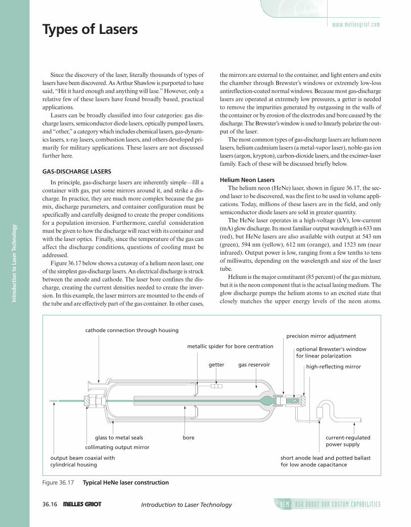
Helium Neon LasersThe helium neon (HeNe) laser, shown in figure 36.17, the sec-
ond laser to be discovered, was the first to be used in volume appli-cations. Today, millions of these lasers are in the field, and onlysemiconductor diode lasers are sold in greater quantity.
The HeNe laser operates in a high-voltage (kV), low-current(mA) glow discharge. Its most familiar output wavelength is 633 nm(red), but HeNe lasers are also available with output at 543 nm(green), 594 nm (yellow), 612 nm (orange), and 1523 nm (nearinfrared). Output power is low, ranging from a few tenths to tensof milliwatts, depending on the wavelength and size of the lasertube.
Helium is the major constituent (85 percent) of the gas mixture,but it is the neon component that is the actual lasing medium. Theglow discharge pumps the helium atoms to an excited state thatclosely matches the upper energy levels of the neon atoms.
Since the discovery of the laser, literally thousands of types oflasers have been discovered. As Arthur Shawlow is purported to havesaid, “Hit it hard enough and anything will lase.” However, only arelative few of these lasers have found broadly based, practicalapplications.
Lasers can be broadly classified into four categories: gas dis-charge lasers, semiconductor diode lasers, optically pumped lasers,and “other,” a category which includes chemical lasers, gas-dynam-ics lasers, x-ray lasers, combustion lasers, and others developed pri-marily for military applications. These lasers are not discussedfurther here.
GAS-DISCHARGE LASERS
In principle, gas-discharge lasers are inherently simple—fill acontainer with gas, put some mirrors around it, and strike a dis-charge. In practice, they are much more complex because the gasmix, discharge parameters, and container configuration must bespecifically and carefully designed to create the proper conditionsfor a population inversion. Furthermore, careful considerationmust be given to how the discharge will react with its container andwith the laser optics. Finally, since the temperature of the gas canaffect the discharge conditions, questions of cooling must beaddressed.
Figure 36.17 below shows a cutaway of a helium neon laser, oneof the simplest gas-discharge lasers. An electrical discharge is struckbetween the anode and cathode. The laser bore confines the dis-charge, creating the current densities needed to create the inver-sion. In this example, the laser mirrors are mounted to the ends ofthe tube and are effectively part of the gas container. In other cases,
output beam coaxial with cylindrical housing
collimating output mirror
glass to metal seals bore
short anode lead and potted ballast for low anode capacitance
current-regulated power supply
high-reflecting mirror
optional Brewster's windowfor linear polarization
precision mirror adjustment
gas reservoirgetter
metallic spider for bore centration
cathode connection through housing
Figure 36.17 Typical HeNe laser construction
w w w . m e l l e s g r i o t . c o m
36ch_LaserGuide_f_v3.qxd 6/8/2005 11:16 AM Page 36.16

1 36.17A S K A B O U T O U R C U S T O M C A P A B I L I T I E SO E M Introduction to Laser Technology
Introduction to Laser Technology
This energy is then transferred to the neon atoms via collisions ofthe second kind (i.e., exciting the neon to a higher energy level asopposed to transferring the energy as kinetic motion). One char-acteristic of the glow discharge is its negative impedance (i.e., increas-ing the voltage decreases the current); consequently, to functionwith a standard current-regulated power supply, a ballast resistormust be used in series with the laser to make the overall impedancepositive.
The popularity (and longevity) of the HeNe laser is based on fivefactors: they are (relative to other lasers) small and compact; theyhave the best inherent beam quality of any laser, producing a vir-tually pure single transverse mode beam (M2 < 1.05); they areextremely long lived, with many examples of an operating life of50,000 hours or more; they generate relatively little heat and areconvection cooled easily in OEM packages; and they have a rela-tively low acquisition and operating cost.
Helium Cadmium LasersHelium cadmium (HeCd) lasers are, in many respects, similar
to the HeNe laser with the exception that cadmium metal, the las-ing medium, is solid at room temperature. The HeCd laser is a rel-atively economical, cw source for violet (442 nm) and ultraviolet(325 nm) output. Because of its excellent wavelength match to photopolymer and film sensitivity ranges, it is used extensively forthree-dimensional stereolithography and holographic applications.
As mentioned above, cadmium, a metal, is solid at room tem-perature. For lasing to occur, the metal must be evaporated from areservoir, as shown in figure 36.18, and then the vapor must bedistributed uniformly down the laser bore. This is accomplishedthrough a process called electrophoresis. Because cadmium willplate out on a cool surface, extreme care must be taken in the designof the laser to contain the cadmium and to protect the optics andwindows from contamination, since even a slight film will intro-duce sufficient losses to stop lasing. The end of life usually occurswhen cadmium is depleted from its reservoir.
Noble-Gas Ion LasersThe noble-gas ion lasers (argon-ion and krypton-ion), have been
the mainstay of applications requiring high cw power in the visible,ultraviolet, and near-infrared spectral regions. High-powerwater-cooled systems can be found in research laboratories aroundthe world; lower-power air-cooled systems are used in a wide vari-ety of OEM applications. Argon-ion lasers are available with out-put up to 7 W in the ultraviolet (333–354 nm) and 25 W or morein the visible regions (454–515 nm), with primary output at 488 nm(blue) and 514 nm (green). Krypton-ion lasers have their primaryoutput at 568 nm (yellow), 647 nm (red), and 752 nm (near infrared).Mixed-gas lasers combine both argon and krypton to producelasers with a wider spectral coverage.
Unlike the HeNe laser, ion lasers operate with a high-intensitylow-pressure arc discharge (low voltage, high current). A 20-W vis-ible laser will require 10 kW or more power input, virtually all ofwhich is deposited in the laser head as heat which must be removedfrom the system by some cooling mechanism. Furthermore, thecurrent densities in the bore, which can be as high as 105A/cm2,place large stresses on the bore materials.
Ion lasers can be broken into two groups: high-power (1–20=W)water-cooled lasers and low-power air-cooled lasers. Both are shownschematically in figure 36.19.
The main features of both lasers are the same. Both use a coiled,directly-heated dispenser cathode to supply the current; both havea gas return path that counteracts gas pumping (non-uniform gas
heater
main anode bore support
helium pump
thermionic cathode
cataphoretic anodecadmium reservoir
cadmium trap
bore
brewster window
Figure 36.18 Construction of a HeCd laser
externalmirrors
Brewster's angle windows
anode
thermioniccathode
disc bore structureexternal solenoid(electromagnet)
water-cooling path
anode
internal mirrors
thermioniccathode
fins for air coolingsolid BeO bore
AIR-COOLED ION LASER
HIGH-POWER WATER-COOLED ION LASER
Figure 36.19 Air-cooled and water-cooled ion lasers
36ch_LaserGuide_f_v3.qxd 6/8/2005 11:16 AM Page 36.17

36.18 1 A S K A B O U T O U R C U S T O M C A P A B I L I T I E SO E MIntroduction to Laser Technology
Intr
oduc
tion
to
Lase
r Te
chno
logy
pressure throughout the length of the tube caused by the chargedparticles moving toward the electrodes).
The bore of an air-cooled system is always made of berylliumoxide (BeO), a ceramic known for its ability to conduct heat. A finstructure is attached to the outside of the ceramic bore, and a blowerremoves the generated heat, typically less than 1 kW.
Water-cooled systems are available with either BeO bores or aconstruction wherein tungsten discs are attached to a thin-walledceramic tube surrounded by a water jacket. The heat from the discsis conducted through the walls of the tube to the surrounding water.The entire bore structure is surrounded by a solenoid electromag-net, which compresses the discharge to increase current densityand minimize bore erosion.
The main life-limiting factors in ion lasers are cathode depletionand gas consumption. The intense discharge drives atoms into thewalls of the discharge tube where they are lost to the discharge.Over time the tube pressure will decrease, causing the discharge tobecome unstable. This is particularly a problem with krypton-ionlasers. Water-cooled systems typically have some refill mechanismto keep the pressure constant. Air-cooled systems typically do not,limiting their practical operating life to approximately 5000 oper-ating hours.
Carbon Dioxide LasersBecause of their ability to produce very high power with rela-
tive efficiency, carbon dioxide (CO2) lasers are used primarily formaterials-processing applications. The standard output of theselasers is at 10.6 mm, and output power can range from less than1 W to more than 10 kW.
Unlike atomic lasers, CO2 lasers work with molecular transi-tions (vibrational and rotational states) which lie at low enoughenergy levels that they can be populated thermally, and an increasein the gas temperature, caused by the discharge, will cause a decreasein the inversion level, reducing output power. To counter this effect,high-power cw CO2 lasers use flowing gas technology to remove hotgas from the discharge region and replace it with cooled (or cooler)gas. With pulsed CO2 lasers that use transverse excitation, the prob-lem is even more severe, because, until the heated gas between theelectrodes is cooled, a new discharge pulse cannot form properly.
A variety of types of CO2 lasers are available. High-power pulsedand cw lasers typically use a transverse gas flow with fans whichmove the gas through a laminar-flow discharge region, into a cool-ing region, and back again (see figure 36.20). Low-power lasersmost often use waveguide structures, coupled with radio-frequencyexcitation, to produce small, compact systems.
Excimer LasersThe term excimer or “excited dimer” refers to a molecular com-
plex of two atoms which is stable (bound) only in an electronically
excited state. These lasers, which are available only as pulsed lasers,produce intense output in the ultraviolet and deep ultraviolet. Thelasers in this family are XeFl (351 nm), XeCl (308 nm), KrF (248 nm), KrCl (222 nm), ArF (193 nm), and F2 (157 nm). Theyare used extensively in photolithography, micromachining, andmedical (refractive eye surgery) applications.
At first glance, the construction of an excimer laser is very sim-ilar to that of a transverse-flow, pulsed CO2 laser. However, themajor difference is that the gases in the system are extremely cor-rosive and great care must be taken in the selection and passivationof materials to minimize their corrosive effects. A system built forCO2 would fail in minutes, if not seconds.
The principal advantage of an excimer laser is its very shortwavelength. The excimer output beam can be focused to a spotdiameter that is approximately 40 times smaller than the CO2 laserbeam with the same beam quality. Furthermore, whereas the longCO2 wavelength removes material thermally via evaporation (boil-ing off material), the excimer lasers with wavelengths near 200 nmremove material via ablation (breaking molecules apart), withoutany thermal damage to the surrounding material.
SEMICONDUCTOR DIODE LASERS
The means of generating optical gain in a diode laser, the recom-bination of injected holes and electrons (and consequent emis-sion of photons) in a forward-biased semiconductor pn junction,
blower
cooling coils
laminar flow discharge region
electrode
electrode
Figure 36.20 Schematics of transverse flow CO2 lasersystem
36ch_LaserGuide_f_v3.qxd 6/8/2005 11:16 AM Page 36.18

1 36.19A S K A B O U T O U R C U S T O M C A P A B I L I T I E SO E M Introduction to Laser Technology
Introduction to Laser Technology
represents the direct conversion of electricity to light. This is avery efficient process, and practical diode laser devices reach a50-percent electrical-to-optical power conversion rate, at least anorder of magnitude larger than most other lasers. Over the past20 years, the trend has been one of a gradual replacement of otherlaser types by diode laser based–solutions, as the considerable chal-lenges to engineering with diode lasers have been met. At the sametime the compactness and the low power consumption of diodelasers have enabled important new applications such as storinginformation in compact discs and DVDs, and the practicalhigh-speed, broadband transmission of information over opticalfibers, a central component of the Internet.
Construction of a double-heterostructure diode laserIn addition to a means to create optical gain, a laser requires a
feedback mechanism, a pair of mirrors to repeatedly circulate thelight through the gain medium to build up the resulting beam bystimulated emission. The stripe structures needed to make a laserdiode chip are formed on a single crystal wafer using the standardphotolithographic patterning techniques of the semiconductorindustry. The substrate crystal axes are first oriented relative to thepatterning such that, after fabrication, a natural cleavage plane isnormal to the stripe direction, and cleaving both ends of the chipprovides a pair of plane, aligned crystal surfaces that act as aFabry-Perot resonator for optical feedback. These mirrors use eitherthe Fresnel reflectivity of the facet (often sufficient because of thehigh gain of diode lasers), or they can be dielectric coated to otherreflectivities. This might be desired, for instance, to protect againstdamage from the high irradiance at the facets. This geometry givesthe familiar edge-emitting diode laser (see figure 36.21).
The semiconductor crystal must be defect free to avoid scatter-ing of carriers and of light. To grow crystal layers without defects,commercial semiconductor lasers use III-V compounds, elementstaken from those columns of the periodic table. These form vary-ing alloys with the addition of dopants that can be lattice-matchedto each other and to the initial crystal substrate. The band gap ofthe semiconductor chosen determines the lasing wavelength region.There are three main families: GaN-based lasers with UV-blue out-puts, GaAs-based lasers with red-near infrared outputs, andInP-based lasers with infrared outputs. These base crystals are pre-cisely doped with Ga, Al, In, As, and P to precisely control the bandgap and index of refraction of the layers in the diode structure.
These compounds are direct band-gap semiconductors withefficient recombination of injected holes and electrons because nophonons (lattice vibrations) are required to conserve momentumin the recombination interaction. The injection layers surround-ing the junction, the cladding layers, can be indirect band-gap semi-conductors (where phonons are involved).
To make a planar waveguide that concentrates the lightin the junction region (confinement between the top and bottomhorizontal planes of the active region in figure 36.21), the cladding
layers are made of an alloy of lower refractive index (larger bandgap) than the active junction region. This is then termed a dou-ble-heterostructure (DH) laser. The output power of the laser ishorizontally polarized because the reflectivity of the planar wave-guide is higher for the polarization direction parallel to the junctionplane. Because the junction region is thin for efficient recombina-tion (typically 0.1 mm), some light spreads into the cladding layerswhich are therefore made relatively thick (typically 1 mm) for ade-quate light confinement.
0.25typical
top contact(1)
p-cladding
p-type active layerand output facet
oxideinsulator
n-claddingp-cladding
n-claddingbottomcontact(5)
9y≅30º
Pout
Qx≅10º
dimensions in mm
Figure 36.21 Schematic of a double heterostructureindex-guided diode laser
laseroutput
spontaneousemission
I, forward drive current
Ith Imax
DPout
DI
Pout , optical output power
Figure 36.22 Definition of threshold current, Ith, andslope efficiency from the curve of light output, Pout vsdrive current I
36ch_LaserGuide_f_v3.qxd 6/8/2005 11:16 AM Page 36.19

36.20 1 A S K A B O U T O U R C U S T O M C A P A B I L I T I E SO E MIntroduction to Laser Technology
Intr
oduc
tion
to
Lase
r Te
chno
logy
Gain guiding and index guiding in diode lasersTo confine the light laterally (between planes perpendicular to
the junction plane), two main methods (with many variants) areused. The first and simplest puts a narrow conductive stripe on thep-side of the device to limit the injected current to a line, giving again-guided laser. There is some spreading of current under thestripe, and the light is restricted only by absorption in the unpumpedregions of the junction. The transverse mode of the laser light istherefore not tightly controlled. Many high-power diode lasers,used for instance in side-pumping another solid-state laser (wheremode control is less critical), are gain guided.
More efficient lateral laser mode control is achieved by fabri-cating, with multiple photolithographic, epitaxial, and etchingsteps, regions of low index of refraction on either side of the lasingstripe (the two lateral n-cladding regions in the upper half of fig-ure 36.21). This confines the light by waveguiding between planesperpendicular to the junction plane as well giving an index-guidedlaser. These lasers produce a stable single transverse mode of low-est order, as required in data storage applications to read compactdiscs, and telecommunications applications where coupling into afiber optic is important.
Threshold current and slope efficiency definitionsOutput power from a diode laser increases linearly with the
drive current excess above the threshold current (see figure 36.22).This steeply rising light output curve is extrapolated backward tothe zero light output intercept to define the threshold current; theweak incoherent light emission for currents below threshold is dueto the spontaneous recombination of carriers such as occurs inLEDs.
When divided by the drive voltage V, the slope of the output vscurrent curve yields the differential (above threshold)electrical-to-optical power conversion efficiency (also termed theslope or quantum efficiency) which ranges from 50 to 80 percent forvarious devices.
Fabrication methods and quantum wellsThree types of epitaxial crystal growth are employed in fabri-
cating the layers of semiconductor alloys for diode laser chips: liq-uid phase epitaxy (LPE), metal-organic chemical vapor deposition(MOCVD), and molecular beam epitaxy (MBE).
Most early diode lasers were made by the LPE process, and itis still in use for many commercial diode lasers and LEDs. In thisprocess, a heated, saturated solution is placed in contact with the sub-strate, and it is cooled, leaving an epitaxial film grown on the sub-strate. High-quality crystal layers are readily produced by thistechnique, but it is hard to control alloy composition. Further-more, making thin layers is difficult. Because Quantum well (QW)
structures, discussed below, require very thin layers. The LPE processis not appropriate for these devices; they are fabricated using theMOCVD or MBE process.
In the MOCVD process, gases transport the reactants to theheated substrate, where they decompose and the epitaxial layerslowly grows. In the high-vacuum MBE process, the reactants areevaporated onto the substrate, giving a very slow, controlled epitaxialgrowth. The equipment for MBE is more expensive, and the processis slower making this process most suitable for critical and com-plex devices of low production volume.
The emergence of the MOCVD and MBE processes made pos-sible improved diode lasers employing quantum well structures astheir active regions. A quantum well is a layer of semiconductor oflow electron (or hole) potential energy between two other layers ofhigher potential energy. The well layer is made thin enough, typi-cally less than 0.01 mm, to be comparable in size to the Bohr radiusof the electron (or hole) in the material. This brings in quantumeffects—the confined carrier acts, in the direction perpendicularto the layer plane, as a one-dimensional particle in a potential well.In practical terms, the density of carriers is greatly increased in thisQW structure, and the laser threshold current decreases by an orderof magnitude. The laser’s active region is effectively an engineered,man-made material whose properties can be designed.
There is a disadvantage to QW lasers: the active region is too thinto make a reasonable waveguide. This problem is solved by insert-ing intermediate layers of graded index between the QW and bothcladding layers. This is termed the graded-index separate-confinement heterostructure (GRINSCH) since the carriers areconfined to the QW while the laser mode is confined by the sur-rounding layers. The electrical and optical confinements are separate.For higher output power, several QWs separated by buffer layers canbe stacked on top of one another,—a multiple quantum well (MQW)structure. A structure with only one quantum layer is designated asingle quantum well (SQL) to distinguish it from a MQW.
The lasing wavelength in QW lasers is determined by both thebulk band gap and the first quantized energy levels; it can be tunedby varying the QW thickness. Further adjustment of the wavelengthis possible with strained quantum QWs. If an epitaxial layer is keptbelow a critical thickness, an alloy with a lattice mismatch to the sub-strate will distort its lattice (in the direction normal to the substrate)to match the substrate lattice instead of causing misfit dislocations.The strain in the lattice of the resulting QW changes its band gap,an effect taken advantage of to put the lasing wavelength into adesired region.
Wavelength stabilization with distributed, surface-emitting output geometries
The wavelength of a AlGaAs diode laser tunes with substratetemperature at a rate of about 0.07 nm/°C, a rapid enough rate thatmany applications require the baseplate of the device to be mountedon a temperature controlled thermoelectric cooler to maintain
Slope efficiency .out=D
D
PV I
(36.25)
36ch_LaserGuide_f_v3.qxd 6/8/2005 11:16 AM Page 36.20

1 36.21A S K A B O U T O U R C U S T O M C A P A B I L I T I E SO E M Introduction to Laser Technology
Introduction to Laser Technology
wavelength stability. Wavelength, threshold current, and efficiencyare all sensitive to changes in temperature. If the laser baseplatetemperature is allowed to drift, in addition to this long-term shiftin wavelength, the output oscillation will jump between driftinglongitudinal cavity modes and thus exhibit small, rapid, discon-tinuous changes in wavelength and/or output power which often areundesirable.
To address this issue, gratings are fabricated into the laser, eitherat the ends of the gain stripe to create a distributed Bragg reflector(DBR) structure, or along the whole length of the gain region to cre-ate a distributed feedback (DFB) structure. The grating has a periodon the order of 200 nm and is fabricated using interferometric tech-niques. (The beam from an argon or HeCd laser is split into two;the beams are are then overlapped to create fringes, which in turnare used to expose the photoresist in the photolythography process.)The gratings work by providing a small reflected feedback at eachindex step. The single frequency whose multiple fed-back reflec-tions add up in phase determines the lasing wavelength and stabi-lizes it against changes in drive current and baseplate temperature.Because the laser operates in a single frequency, noise is also reduced.DBR and DFB lasers are used extensively as telecommunicationlight sources.
The DFB laser is an edge emitter. In the second-order gratingsfabricated in both DFB and DBR lasers, the first-order diffractionis perpendicular to the surface of the grating. By providing an out-put window on one of the gratings in a DBR laser, the output canbe brought out through the surface of the chip, i.e., a surface-emit-ting laser.
Recently, another surface-emitting structure, the vertical-cavity surface-emitting laser (VCSEL), has come into use in telecom-munication links. In this structure (see figure 36.23) multilayermirrors are fabricated on the top and bottom of the QW gain regionto give feedback. Consequently, the laser output is perpendicularto the active QW plane.
The epitaxial growth process of this structure is more difficultthan that for edge emitters This is because provision must be madeto channel current flow around the mirrors to reduce device resis-tance (for clarity, the bypass channels are omitted in figure 36.23)and because precise control of the mirror layer thicknesses is neededto locate standing wave peaks at the QW active layer(s). Counter-ing these drawbacks, by having no facets to cleave, these lasers havea similar topology to LEDs. They can be tested at the wafer leveland packaged using similar low-cost manufacturing methods. Inaddition, VCSELs have large-area circular beams (defined by thecircular limiting aperture of the mirrors) and low threshold cur-rents so they couple well into optical fibers and fit well in low-power(~1 mW) communication system applications.
Diode laser beam conditioningBecause the emitting aperture is small on a typical diode laser,
beam divergences are large. For example, the emitting area for the
HRmirror stacks(dielectricor DBRs)
substrate
top contact
QWactive layer
bottomcontact
Pout
Figure 36.23 Schematic of the VCSEL structure, withlight emitted perpendicular to the active layer
index-guided laser shown in figure 36.21 might be as small as 3#1 mm, resulting in diverges of 10#30 degrees. The optics neededto collimate this beam or to focus it into a fiber must work at a highnumerical aperture, resulting in potential lens aberrations, andrequiring critical focusing because of short depth of field. Focallengths must be kept short as well or the optics rapidly becomelarge. The beam inself is elliptical and may be astigmatic. It is oftendesireable to first circularize the beam spot with an anamorphicprism pair or cylinder lens before coupling the laser output into anoptical train. Higher-power lasers with high-order modes causeadditional problems when coupling their beams into a fiber or opti-cal system. A wide variety of specialized components are availableto address these issues, from molded miniature aspherical lensesto hyperbolic profile fiber cylinder lenses, but all require criticalfocusing adjustment in their mounting into the laser diode hous-ing. For these reasons many diode lasers are offered with beam-correcting optics built in by the manufacturer who has the appro-priate tooling for the task. Typically these lasers are available as col-limated units, or as fiber-coupled (“pigtailed”) devices.
High-power diode lasersSingle transverse mode diode lasers are limited to 200 mW or
less of output power by their small emitting aperture. The facetarea is so small (about 3#1 mm) that this power still represents ahigh irradiance (~7 MW/cm2). The output is limited to this level tostay safely under the irradiance that would cause damage to thefacet.
Enlarging the emitting area with an increase of the lateral widthof the active stripe is the most common method of increasing the
36ch_LaserGuide_f_v3.qxd 6/8/2005 11:16 AM Page 36.21

36.22 1 A S K A B O U T O U R C U S T O M C A P A B I L I T I E SO E MIntroduction to Laser Technology
Intr
oduc
tion
to
Lase
r Te
chno
logy
laser output power, but this also relaxes the single transverse modeconstraint. Multiple transverse lateral modes, filaments, and lat-eral mode instabilities arise as the stripe width increases. For exam-ple, in a GaAs laser running at 808 nm, the output power riseslinearly from 500 mW to 4 W as the lateral width of the emittingaperture increases from 50 to 500 mm. Howerer, the M2 value of thebeam in this plane increases from 22 to 210. The M2 increase makesit difficult to couple these devices to fibers, but they find consider-able application in pumping solid-state laser chips designed toaccept a high-numerical-aperture focus.
The pump diode lasers for even higher-power DPSS lasers aremade as linear arrays of 20 or more stripe emitters integrated sideby side on a 1-cm-long semiconductor bar. The bar is mounted ina water-cooled housing to handle the heat load from the high drivecurrent. These diode laser arrays provide from 20 to 40 W of con-tinuous output power at wavelengths matching the absorptionbands of different laser crystals (e.g., 808 nm for pumping Nd:YAGlasers). The individual stripe emissions are not coherently related,but bars can be used to side pump a laser rod, just as the arc lampsthey replace formerly did. Another common delivery geometry isa bundle of multimode fibers, fanned into a line of fibers on one endwith each fiber butted against an individual stripe on the bar, withthe other end of the bundle gathered into a circular grouping. Thisconverts the bar output into a round spot focusable onto the endof the crystal to be pumped.
Finally, for even more output, a few to a dozen bars are mountedlike a deck of cards one on top of another in a water-cooled pack-age, connected in series electrically, and sold as a stacked array.These can deliver in excess of 500W output power from one device.
Packaging, power supplies, and reliabilityFor low-power lasers, the industry uses standard semiconduc-
tor device package designs, hermetically sealed with an output win-dow. Lasers with higher power dissipation come with a copperbaseplate for attachment to a finned heat sink or thermoelectriccooler (TEC). Many are offered coupled into a fiber at the manu-facturing plant in a pigtailed package (with an output fiber attached)because of the criticality in mounting the coupling optics as men-tioned above.
Careful heat sinking is very important because all the majordevice parameters—wavelength, threshold current, slope efficiency,and lifetime—depend on device temperature (the cooler, the better).Temperature-servoed TECs are preferred for stable operation withthe temperature sensor for feedback mounted close to the diodelaser.
Diode lasers are susceptible to permanent damage from staticelectricity discharges or indeed any voltage transient. Their lowoperating voltage (~2 V) and ability to respond at high speed meansthat a static discharge transient can be a drive current spike above themaximum safe level and result in catastrophic facet damage. All theusual antistatic electricity precautions should be taken in working
with diode lasers: cotton gloves, conductive gowns, grounded wriststraps, work tables, soldering irons, and so on. Correspondingly,the drive current power supply should be filtered against surgesand include “slow starting” circuitry to avoid transients.
Diode lasers degrade with high power and long operating hoursas crystal defects migrate and grow, causing dark lines or spots inthe output mode pattern and increases in threshold current ordecreases in slope efficiency. The best way to prolong life is to keepthe laser baseplate running cool. Remember that accelerated lifetests are run by operating at high baseplate temperature. Expecta-tions for the median life of a device are set from measurementsof large populations—individual devices can still suddenly fail.Nevertheless, the industry expectations today for standard diodelasers run within their ratings is ~105 hours of operation forlow-power diode lasers and perhaps an order of magnitude less forthe high-power versions.
Summary of applicationsThe applications mentioned in the discussion above, and a few
others, are summarized in the following table and ordered by wave-length. The newer GaN lasers provide low power (10–100 mW)blue and UV wavelengths finding applications as excitation sourcesfor biomedical fluorescence studies (DNA sequencing, confocalmicroscopy). The dominant application for diode lasers is as read-outs for optical data storage, followed by growing numbers in usein telecommunications. For high-power (>1 W) diode lasers, themain application is as optical pumps for other solid state lasers.
OPTICALLY PUMPED LASERS
Optically pumped lasers use photons of light to directly pumpthe lasing medium to the upper energy levels. The very first laser,based on a synthetic ruby crystal, was optically pumped. Opticallypumped lasers can be separated into two broad categories:lamp-pumped and laser pumped. In a lamp-pumped laser, the las-ing medium, usually a solid-state crystal, is placed near a high-inten-sity lamp and the two are surrounded by an elliptical reflector thatfocuses the light from the lamp into the crystal, as shown in figure36.24. In laser-pumped systems, the light from another laser isfocused into a crystal (or a stream of dye), as shown in figure 36.25.
In general, ignoring the efficiency of the pump laser itself, laserpumping is a much more efficient mechanism than lamp pumpingbecause the wavelength of the pump laser can be closely matchedto specific absorption bands of the lasing medium, whereas mostof the light from a broad-spectrum lamp is not usefully absorbedin the gain medium and merely results in heat that must be removedfrom the system. Furthermore, the size of the laser pump beamcan be tightly controlled, serving as a gain aperture for improvingthe output mode characteristics of the pumped laser medium. Onthe other hand, laser pumping is often not suitable for high-energyapplications where large laser crystals are required.
36ch_LaserGuide_f_v3.qxd 6/8/2005 11:16 AM Page 36.22

1 36.23A S K A B O U T O U R C U S T O M C A P A B I L I T I E SO E M Introduction to Laser Technology
Introduction to Laser Technology
Diode-pumped solid-state (DPSS) lasers, a class of laser-pumpedlasers, will be discussed in detail below.
DIODE-PUMPED SOLID STATE LASERS
The DPSS laser revolutionThe optical difficulties encountered with diode lasers—diffi-
culty in coupling to the high divergence light, poor mode qualityin the slow axis of wide-stripe lasers, low output power from sin-gle-transverse-mode lasers— led to a new philosophy (figure 36.26)about how best to use these efficient, long-lived, compact
flashlamp
lasing crystal
output coupler
high reflectorelliptical reflector
Figure 36.24 Schematic of a lamp-pumped laser
Wavelength Lattice
l (nm) Material* Application
375 GaN Biomedical fluorescence
405 GaN Biomedical fluorescence, DVD mastering
440 GaN Biomedical fluorescence, HeCd laser replacement
473 GaN Biomedical fluorescence
635 GaAs Pointers, alignment, HeNe laser replacement
650 GaAs DVD readouts
670 GaAs Barcode scanners, pointers, alignment
780 GaAs Audio CD readouts
785 GaAs Raman spectroscopy
808 GaAs Optical pumps for Nd:YAG lasers, thermal printing
940 InP Optical pumps for Yb:YAG lasers
980 InP Optical pumps for Er fiber telecom amplifiers
1310 InP Input source for telecom short-wavelength channels
1455 InP Optical pump for Raman gain in standard telecom fiber
1550 InP Input source for telecom long-wavelength channels
Diode Laser Applications
*Ga, Al, In, P dopants are added to form the required layered strutures
pump laser
mode-matchingoptics
lasing crystal
output coupler
high reflector(transmits pump wavelength)
Figure 36.25 Schematic of a laser-pumped laser
light sources. This concept, championed in the 1980s by a group atStanford University headed by Prof. Bob Byer, has been termedthe diode-pumped solid state (DPSS) laser revolution.
The logic is simple. The primary light source (the diode laser)pumps another laser (an infrared crystal laser) to convert to a goodmode, the beam of which is wavelength converted (by nonlinearoptics techniques) to a visible output. The diode laser source replacesthe discharge lamp for optically pumping the gain crystal in a tra-ditional, high-efficiency, infrared laser. The infrared beam is gen-erated in that independent resonator with a good mode, andconsequently it can be efficiently converted with an intracavity non-linear crystal to a visible beam with a good mode. Thoughpower is lost at each step, the result is still a single-mode visible beamgenerated with a total electrical-to-optical conversion efficiency ofseveral percent. These DPSS lasers are replacing the older visiblegas lasers whose conversion efficiencies rarely reach 0.1 percent.
36ch_LaserGuide_f_v3.qxd 6/8/2005 11:16 AM Page 36.23

End-pumping with barsWith these two new degrees of freedom, laser designers real-
ized they could create optical trains that would give them end-pump-ing system efficiencies (achieve good overlap between pump andlasing modes) with diode arrays as pump sources to obtain a lowerdiode cost per watt in their systems. This produced an explosionof unique DPSS laser designs generically described as “end-pump-ing with bars.”
Figure 36.27 shows the example previously mentioned, deliveringthe array light through a fiber bundle, with the fibers at one endspread out to butt align with the linear stripes of an array, and theother end of the bundle gathered to an approximately circular spot.
Although the circular spot is large, its focal image, formed withhigh numerical aperture (NA) optics, is small enough to satisfac-torily overlap the IR cavity laser mode. The small depth of focus,from the high NA optics, is inconsequential here because of theshort absorption depth in the Nd:YVO4 laser crystal. The laserhead can be disconnected from the diode modules at the fiber cou-pler without loss of alignment.
In another example, an even higher-NA optic (comprising acylinder lens and a molded aspheric lens) was used to directly focusthe 1-cm width of a micro-lensed array bar onto the end of aNd:YVO4 gain crystal. This produced an oblong pump spot, butgood overlap with the IR cavity mode was achieved by altering theinfrared cavity (inserting two intracavity beam expansion prisms inthat arm) to produce a 5:1 elliptical cavity mode in the gain crys-tal. Another design used a nonimaging pyramidal “lens duct” tobring in the pump light from a diode laser stack to the end of again crystal. Yet another brought light from several arrays into alasing rod centered in a diffuse-reflecting cavity by means of severalplanar (glass-slide) waveguides, each piercing a different sector ofthe reflector sidewall. These are but a few of the design approachesthat have been successfully taken.
36.24 1 A S K A B O U T O U R C U S T O M C A P A B I L I T I E SO E MIntroduction to Laser Technology
Intr
oduc
tion
to
Lase
r Te
chno
logy
End- and side-pumping geometriesThe first DPSS lasers were made by focusing the diode light
from a single laser diode emitter through the high-reflector coating(at 1.06 mm) on the end of the Nd:YAG rod. This “end-pumping”geometry provide good overlap between the pumped volume andthe lasing volume, but it limited the pump power to that availablefrom single-mode diode emitters.
In order to increase laser output and reduce cost (diode laserssuitable for end pumping are twice as expensive as diode laserarrays), diode arrays were mounted along the length of the laserrod. However, because of poor overlap of the pump beam with the1.06 mm beam, the efficiency of this “side-pumping” technique wasonly half that of end-pumping geometries. No pump diode costsavings resulted.
Then in the late 1980s two advances were made. First, a varietyof new laser rod materials, better tailored to take advantage ofdiode laser pumps, were introduced. Nd:YVO4 crystals have fivetimes the gain cross section of Nd:YAG, and the Nd can be dopedinto this crystal at much higher concentrations. This decreases theabsorption depths in the crystal from cm to mm, easing the colli-mation or focusing quality required of the pump beam. This crys-tal had been known, but could be grown only to small dimensions,which is acceptable for diode-pumped crystals. Another crystal intro-duced was Yb:YAG, pumped at 980 nm and lasing at 1.03 mm—leaving very little residual heat in the crystal per optical pumpingcycle and allowing small chips of this material to be pumped athigh levels.
Second, means were devised to make micro-cylindrical lenses(focal lengths less than a mm) with the correct surfaces (one typeis a hyperbolic profile) for collimating or reducing the fast-axisdivergence of the diode laser output. With good tooling and beamcharacterization these are correctly positioned in the diode beamand bonded in place to the diode housing. This allows more con-ventional lenses, of smaller numerical aperture, to be used in sub-sequent pump light manipulations.
primary lightsource
pump diode laser
IR laser crystal
nonlinearcrystal
modeconverter
wavelengthconverter
hT = hPhMh
l
≅ 3%
good eff.,hl ≅ 50%
good mode,M2 = 1
good eff.,h
M ≅ 12%
good mode,M2 = 1.5
high eff.,hP = 50%
poor mode,M2 = 50
Figure 36.26 The logic for DPSS lasers
36ch_LaserGuide_f_v3.qxd 6/8/2005 11:16 AM Page 36.24

1 36.25A S K A B O U T O U R C U S T O M C A P A B I L I T I E SO E M Introduction to Laser Technology
Introduction to Laser Technology
output4
focusingoptics
fiberbundle
HR
20 W
diode bar
20 W
diode bar
Nd:YVO
Figure 36.27 Schematic of an “end-pumping with bars”geometry using fiber bundle delivery, one of many vari-ants on the DPSS laser theme
Microchip lasersAnother procedure that can be used to make available potentially
inexpensive, mass produced, low power, visible output DPSS lasersis mimicking semiconductor chip processing methods. In the late1980s, MIT Lincoln Labs took this approach and created the“microchip” laser. A thin Nd:YVO4 plate is polished flat and thendiced into ~2-mm-square chips. Each of these chips is then opticallycontacted to similar, flat, diced KTP doubling crystal plates tomake a cube. Prior to dicing, the surfaces that will become theouter cube surfaces are coated for high reflectivity at 1.06 mm.When single-mode diode laser pump light is focused through onemirrored end of the cube, the heat produced makes athermally-induced waveguide that creates a stable cavity for IR las-ing. Since the KTP crystal is within this cavity, the IR lasing is con-verted to a 532-nm (green) output beam with 10’s of milliwats ofoutput. The diode temperature must be controlled to maintain a sta-ble pump wavelength and thermal waveguide. In addition, the cubetemperature should be stabilized. Because of the short cavity, theIR laser operates at a single longitudinal mode, and the cavity lengthmust be thermally tuned to keep the mode at the peak of the gaincurve. Laser operation in a single frequency suppresses “greennoise,” discussed next.
The “green noise” problemAs the early DPSS laser designs giving visible-output beams
were being introduced, it became apparent that there was a prob-lem unique to this architecture. The visible output power, 532 nmin the green spectrum, could break into high-frequency chaoticoscillations of nearly 100-percent peak-to-peak amplitude. Thiswas named the “green problem” by Tom Baer (then atSpectra-Physics), who in 1986 showed the effect to be due to the dom-inance of sum-frequency-mixing (SFM) terms coupling different lon-gitudinal modes over second-harmonic-generation (SHG) terms,in the nonlinear conversion step from IR to visible output. Several
conditions (all met by the new laser designs) lead to this effect:(1) the IR laser cavity is short (~10 cm or less) with only a few lon-gitudinal modes oscillating, (2) nonlinear conversion efficienciesare high (20% or more), and (3) nonlinear phase-matching band-widths span several longitudinal mode spacings (true of the com-monly used KTP doubling crystal). Then the sum frequency mixingoutput losses couple the longitudinal modes in relaxation oscilla-tions where the turn on of one mode turns off another.
Two early solutions to this problem emerged. The first is tomake the IR cavity long enough to give hundreds of oscillatingmodes, so that the noise terms average to insignificance as in a longgas laser. The second is to make the IR oscillation run on a singlelongitudinal mode so that there are no SFM terms. This can be doneby using intracavity frequency control elements such as an etalon,or by using a ring cavity (with a Faraday-effect biasing element tomaintain the direction of light travel around the ring). Ring cavi-ties eliminate the standing-wave interference effect of linear cavities,termed “spatial hole burning,” and the laser runs single frequencywhen this is done. As more experience was gained with DPSS laserdesign, other clever solutions to the “green problem” were found,tailored to each particular device and often held as trade secrets. Itcan be surmised that these involve precise control of wavelength, spa-tial hole burning, beam polarization, and cavity-element opticalpath differences to reduce the strength of longitudinal mode SFMterms.
Uniqueness of DPSS laser designs and laser reliabilityUnlike the gas lasers they replace, no universal approach is
applied in the details of different DPSS laser designs and laser mod-els. There is a large variety of solutions to the major problems,many solutions are unique, and many are held as proprietary. Majordesign differences are found in:$ the means for optically coupling the pumping light into the
gain medium,
$ the management of the thermal lens produced by absorptionof the pump light in the cavity,
$ the control of green noise,
$ the strain-free mounting, heat sinking, and placement of thesmall lasing and nonlinear crystals in the laser cavity, and
$ the hermetic sealing of the laser cavity to protect the oftendelicate crystals and critical alignments of components
Note that because the intracavity space must be hermeticallysealed there usually is no field repair, maintenance, or adjustmentof a DPSS laser head. If it fails, it is returned to the manufacturer.
It is evident that DPSS lasers are a lot less generic than the gaslasers they replace. For a problem with a particular laser model,there may be no standard solution available in the technical liter-ature. With so many variables, there often are surprises when newdesigns are first manufactured and introduced. Under these cir-cumstances, the user is advised to pick a supplier with a record of
36ch_LaserGuide_f_v3.qxd 6/8/2005 11:16 AM Page 36.25

36.26 1 A S K A B O U T O U R C U S T O M C A P A B I L I T I E SO E MIntroduction to Laser Technology
Intr
oduc
tion
to
Lase
r Te
chno
logy
years of consistent manufacture, who has over time dealt with hisown unique set of component and assembly problems. If this adviceis followed, then the expectation with current products is that anew DPSS laser will operate reliably for 10,000 hours or more.
An example of a DPSS laser product line—the Melles Griot visible output lasers
Figure 36.28 depicts the mix of laser crystals, laser operatingwavelengths, and doubling crystals generating the four visible out-put wavelengths of the present Melles Griot product line of con-tinuous wave DPSS lasers.
Other notable DPSS lasersA brief discussion of three other significant DPSS laser devel-
opments conclude this section. The Er-doped fiber amplifier (EDFA) is not a laser, but it is an
optically pumped amplifier for the 1550-nm long-wavelengthlong-haul fiberoptic channels that make the worldwide web possi-ble. Pumping an Er-doped silica fiber with 980-nm diode laser lightinverts the populations of energy levels in the Er ions to providegain for optical telecommunication signals run through the samefiber. This optical amplifier is much simpler than the discrete elec-tronic repeaters it replaced. A Lucent Technologies executiveexpressed the importance of this when he said: “What broke [wave-length division multiplexing telecommunications] free was the inven-tion of the [EDFA] optical amplifier.”
The Q-switched industrial DPSS laser is a 1-W-average-power,ultraviolet (355 nm), high-repetition-rate (30 kHz) system. Output
is obtained by doubling the 1.064-mm Q-switched fundamental togreen at 532 nm, and then mixing the green beam with the residualtransmitted infrared to 355 nm. This process is straightforward ina high-peak-power pulsed beam—just a matter of inserting theappropriate doubling and tripling crystals. What is remarkable isthat DPSS laser designs have matured sufficiently to make this pos-sible in a hands-off, long lived, system rugged enough to survive andbe useful in an industrial environment.
The double-clad fiber laser is shown in figure 36.29. Fiber laserswork by optically pumping (with a diode laser) a doped fiber andadding mirrors for feedback at either end of the fiber. In the dual-cladfiber, the Yb-doped single-mode fiber core is surrounded by a largediameter cladding (with a corrugated star-shaped cross section inthe figure) that is itself clad by a low-index polymer coating. Diodelaser light at 940 nm is readily launched into and guided in the largediameter outer cladding, and the corrugated cross-section of thisfiber suppresses the helical ray modes of propagation that would havepoor overlap with the inner core. Over the length of the fiber, thepump light is absorbed by the single-mode core, and high- powerlasing near 1.03 mm in a low- order mode is produced. The quan-tum efficiency of the Yb lasing cycle (ratio of pump wavelength tolasing wavelength) is 91 percent, which leaves little heat depositedin the fiber. Over 1 kW of output at 80-percent slope efficiency hasbeen produced in such a fiber laser. These will become importantlaser sources for industrial applications.
pump diode808 nm
couplingoptics
Nd:YVO41064 nm
LBO/KTP
Nd:YVO4914 nm
BBO
LBO
LBO
Nd:YAG946 nm
Nd:YAG1123 nm
IR laserCrystal
SHGnon-linear
crystall
output
532 nm
457 nm
473 nm
561 nm
Figure 36.28 Melles Griot DPSS laser optical trains for producing four different visible output wavelengths
36ch_LaserGuide_f_v3.qxd 6/8/2005 11:16 AM Page 36.26

1 36.27A S K A B O U T O U R C U S T O M C A P A B I L I T I E SO E M Introduction to Laser Technology
Introduction to Laser Technology
MA
XIM
UM
PO
WER
(m
W)
WAVELENGTHS (nm)
1
10
100
1000
10,000
15231064840830780752685676675670647635633612594568561543532520514502496488483476473465 472457454442430325 405
Wavelengths available from Melles Griot lasers.
laserdiode array silica cladding
single-mode core:Yb+3
low-index polymer
single-modelaser output
Figure 36.29 Schematic diagram of the structure of adouble-clad fiber, and the method of pumping the innercore by direct illumination into the large diameter of theouter cladding
561-nm DPSS Laser
The newest addition to the Melles Griot laser productline is a DPSS laser with yellow output at 561 nm,an ideal excitation wavelength for biomedical fluorescence.
This 16.5-cm-long laser head delivers 10 mW of output power, and consumes less than 10 W ofwall plug power.
The laser is pumped by a 1-W single stripe diodelaser. Frequency-selective elements in the cavity limitIR oscillation to the 1.123 mm Nd line (one of theweaker lines in the 1.064 mm manifold) and constrainthis oscillation to a single longitudinal mode. Theoutput is low noise (0.5 percent rms) with excellentmode quality (M2 < 1.2). Polarization is vertical withrespect to the mounting surface with an extinctionratio of >100:1. Life tests predict an expected20,000 hours of operation.
561-nm yellow diode pumped solid-state laser
Available Wavelengths
36ch_LaserGuide_f_v3.qxd 6/8/2005 11:16 AM Page 36.27

36.28 1 A S K A B O U T O U R C U S T O M C A P A B I L I T I E SO E MIntroduction to Laser Technology
Intr
oduc
tion
to
Lase
r Te
chno
logy
Laser Applications
PhotolithographyLasers are used throughout the manufacture of semiconductor
devices, but nowhere are they more important than in exposingphotoresist through the masks used for creating the circuits them-selves. Originally, ultraviolet mercury lamps were used as the lightsources to expose the photoresist, but as features became smallerand more complex devices were put on a single wafer, the mercurylamp’s wavelengths were too long to create the features. Approxi-mately ten years ago, manufactures started to switch to ultravioletlasers operating at approximately 300 nm to expose the photoresist.Manufacturers are now using wavelengths as short as 193 nm to getthe resolution needed for today’s semiconductor integrated circuitapplications.
Marking and ScribingLasers are used extensively in production to apply indelible,
human and machine-readable marks and codes to a wide varietyof products and packaging. Typical applications include markingsemiconductor wafers for identification and lot control, removingthe black overlay on numeric display pads, engraving gift items,and scribing solar cells and semiconductor wafers.
The basic marking system consists of a laser, a scanning head,a flat-field focusing lens, and computer control. The computerturns the laser beam on and off (either directly of through a mod-ulator) as it is scanned over the surface to make the mark. Depend-ing upon the application, scanning may occur in a raster pattern(typical for making dot-matrix marks) or in a cursive pattern, withthe beam creating letters one at a time. The mark itself results eitherfrom ablation of the surface of the material, or by a photochemi-cally induced change in the color of the material. Another mark-ing technique, used with high-energy pulsed CO2 and excimer lasers,is to shine the light through a mask containing the marking patternand focusing the resulting image onto the marking surface.
Laser scribing is similar to laser marking, except that the scanpattern is typically rectilinear, and the goal is to create microscor-ing along the scan lines so that the substrate can be easily brokenapart.
A wide variety of materials, including metal, wood, glass, sili-con, and rubber, are amenable to laser marking and scribing. Eachmaterial has different absorption and thermal characteristic, andsome even have directional preferences due to crystalline structure.Consequently, the type of laser used depends, to some extent, on thematerial to be marked (e.g., glass transmits the 1.06 mm outputfrom a YAG laser but absorbs the 10.6 mm output from a CO2 laser). Other considerations are the size of the pattern, thespeed of the scan, cosmetic quality, and cost.
Currently, most volume marking applications are performedwith lamp-pumped YAG-based pulsed or Q-switched lasers. Pulsedand cw CO2 lasers make up the bulk of the remainder. However,DPSS and fiber lasers are encroaching on this field owing to theirhigher reliability and lower operating cost. Because of their very short
Lasers have become so much a part of daily life that many peo-ple may not realize how ubiquitous they are. Every home with a CDplayer has a laser; hardware stores are now selling a wide variety oflaser levels; many, if not most, computers, printers, and copiers areusing laser technology. Laser applications are so numerous that itwould be fruitless to try to list them all; however; one can give someillustrative examples of how lasers are used today.
INDUSTRIAL APPLICATIONS
High-power lasers have long been used for cutting and weldingmaterials. Today the frames of automobiles are assembled usinglaser welding robots, complex cardboard boxes are made withlaser-cut dies, and lasers are routinely used to engrave numbersand codes on a wide variety of products. Some less well-knownapplications include three-dimensional stereolithography and photolithography.
Three-Dimensional StereolithographyOften a designer, having created a complex part on a CAD
machine, needs to make a prototype component to check out thedimensions and fit. In many cases, it is not necessary for the pro-totype to be made of the specified (final) material for this checkingstep, but having a part to check quickly is important. This is whererapid prototyping, i.e., three-dimensional stereolithography, comesin. The stereolithography machine consists of a bath of liquid pho-topolymer, an ultraviolet laser, beam-handling optics, and com-puter control (see figure 36.30). When the laser beam is absorbedin the photopolymer, the polymer solidifies at the focal point of thebeam. The component design is fed directly from the CAD pro-gram to the stereolithography computer. The laser is scannedthrough the polymer, creating, layer by layer, a solid, three-dimensional model of the part.
flat-field focusing lens
x-y scanning mirror
UV laser
moving vertical stage
prototype part
chemical bath
Figure 36.30 A laser stereolithography system for rapidprototyping of three-dimensional parts
w w w . m e l l e s g r i o t . c o m
36ch_LaserGuide_f_v3.qxd 6/8/2005 11:16 AM Page 36.28

1 36.29A S K A B O U T O U R C U S T O M C A P A B I L I T I E SO E M Introduction to Laser Technology
Introduction to Laser Technology
HeNelaser
ellipticallypolarized beam
surface film
receiver 2 receiver 1
polarizingbeamsplitter
Figure 36.31 Surface film thickness measurement
Twyman-Greeninterferometer
beamsplittersurface ofinterest
detectordetector
ratio amp
CRT
HeNe laser
Figure 36.32 Interferometric measurement
wavelengths (100–300 nm), excimer lasers are used in applicationsrequiring extremely high resolution, or whose materials would ter-mally damage at longer wavelengths.
Noncontact measurementThere are many types of laser-based noncontact measurement
techniques in use today including scatter measurement, polarime-try and ellipsometry, and interferometric measurement.
Scatter Measurement: In the semiconductor industry, patterns ofmaterial are deposited on a wafer substrate using photolithographicprocesses. Defects on the wafer can result in poor reliability, dis-connects in circuitry, or complete circuit failure. Consequently man-ufacturers need to map the wafer to determine the defects’ locationand size so that they can either be eliminated or avoided. To do this,they scan the wafer with a laser and measure backscatter with avery sensitive photodetector array.
Lasers used in this application have to have excellent pointingstability, constant wavelength and power stability to calculate thecorrect size of the defects through complex algorithms, and lownoise so the little scatter the defect makes can be distinguished fromthe background laser light. Blue 488-nm argon ion lasers have beenthe laser of choice for many years. However; as lithography hasshifted to shorter and shorter ultraviolet wavelengths, however, weare beginning to see the metrologic techniques for wafer defectmeasurement also moving to shorter wavelengths. Ultraviolet diodeand solid-state lasers are likely to replace the ion laser in the nextgeneration of instruments.
Polarimetry and Ellipsometry: The optical phase thickness of a thinfilm can be carefully measured using polarimetry or ellipsometry.A beam of known polarization and phase state enters the thin filmlayer at an angle. The thin film has a known index of refraction.
The measured phase change in the reflected beam is then corre-lated to an optical phase thickness for that layer using the knownindex of refraction. This technique can also be used with a thickertransparent media, such as glass, where changes in the polariza-tion and phase state of a beam scanned across the substrate indi-cate variations in index of refraction due to inclusions orstress-induced birefringence. The most common lasers used in theseapplications are violet, red and near infrared single-emitter laserdiodes and mid-visible diode-pumped solid-state lasers owing to theircw output, low noise, and compact sizes.
Interferometric Measurement: Interferometric measurement canbe used for high-resolution position measurement as well as formeasuring waveform deformation of optical beams as they passthrough a component or system.
The technique uses the wave periodicity of the light beam as avery fine ruler. The position of an object in the path of the beam iscomputed from the phase of the light reflected from it. Interfer-ence between the object beam and a reference beam provides mea-sureable intensity variations which yield this phase information.Distance and velocity measurement can be performed for movingobjects as long as the fringe-recording mechanism is paced with it.
Typical applications of this technique include positioning ofmasks for the lithography process, mirror distance correlation withinan FTIR spectrometer, optical feedback in many high-resolutionpositioning systems, and determining the alignment and flatness ofhard disk drive heads.
For applications requiring measurement over a long path length,lasers with a single longitudinal mode and long coherence lengthare often required. In these cases, frequency-stabilized helium neonlasers or a solid-state lasers with frequency selective elements areused.
36ch_LaserGuide_f_v3.qxd 6/8/2005 11:16 AM Page 36.29

techniques (see above). In many cases, the region of interest for flu-orescence correlation spectroscopy is the first 100 to 200 nm of thesample’s surface. However, the excitation depth (vertical resolu-tion) for conventional confocal spectroscopy is 1 to 1.5 mm, lead-ing to low signal-to-noise ratios and diminished accuracy.
One means of reducing the excitation volume is to use totalinternal reflection (TIR) techniques. If a laser beam, passing througha high index material (e.g., glass at n≅1.5) strikes an interface witha lower index sample material (e.g., an aqueous solution at n≅1.3)at an oblique angle, there is an angle of incidence (the critical angle)at which all of the light will be completely reflected at the interface,and none will pass into the lower-index material. The critical angleis given by
where nt is the index of the transmitting (lower index) material andni of the incident material.
Because the beam is completely reflected at the interface, thereis no energy flux across the interface; there is, however, an electro-magnetic field generated in the lower index material, determined bythe boundary conditions on the electric and magnetic fields at theinterface. This transmitted wave is evanescent, propagating alongthe surface of the interface, but decaying in intensity exponentiallywith depth, limiting excitation to a few hundred nanometers—fiveto ten times better resolution than with confocal techniques alone.
Various techniques have been used to obtain TIR. Most com-monly, the laser beam is brought in through a prism, as shown infigure 36.34. Another technique is to bring the beam in through
36.30 1 A S K A B O U T O U R C U S T O M C A P A B I L I T I E SO E MIntroduction to Laser Technology
Intr
oduc
tion
to
Lase
r Te
chno
logy
SCIENTIFIC APPLICATIONS
Lasers are used extensively in the scientific laboratory for awide variety of spectroscopic and analytic tasks. Two interestingexamples are confocal scanning microscopy and time-resolved spectroscopy.
Time-resolved spectroscopyTime-resolved spectroscopy is a technique used to observe phe-
nomena that occur on a very short time scale. This technique hasbeen used extensively to understand biological processes such aphotosynthesis, which occur in picoseconds (10412 seconds) orless. A fluorescing sample is excited by a laser whose pulse lengthis much shorter than the time duration of the effect being observed.Then, using conventional fluorescence spectroscopy measurementtechniques, the time domain of the fluorescence decay process canbe analyzed. Because of the speed of the processes, mode-lockedlasers are used as the exciting source, often with pulse compressionschemes, to generate pulses of the femtosecond (10415 sec) timescale, very much faster than can be generated by electronic circuitry.
Confocal scanning microscopyScanning microscopy is used to build up a three-dimensional
image of a biological sample. In standard light microscopy, a rela-tively large volume of the sample is illuminated, and the resultantlight gathered by the objective lens comes not only from the planein focus itself, but also from below and above the focal plane. Thisresults in an image that contains not only the in-focus light, butalso the haze or blur resulting from the light from the out-of-focusplanes. The basic principle of confocal microscopy is to eliminatethe out-of-focus light, thus producing a very accurate, sharp, andhigh-resolution image. A schematic of a confocal microscope isshown in figure 36.33. A visible laser is used as the light source toproduce a distinct and spatially constrained point source of illu-mination. This light is then focused on the sample. A pinhole isplaced in front of the detector at an optical distance that is exactlythe same as the optical distance between the focus point and the illu-minating source point (the confocal condition). Consequently,only the light generated at the illuminating point will, upon reflec-tion or scattering from the sample, pass through the pinhole infront of the detector; out-of-focus light will be blocked by the pin-hole. The signal from the detector is then digitized and passed toa computer. The complete image is digitally built up by scanningthe sample in the x and y directions.
TIR and Fluorescence Correlation SpectroscopyFluorescence correlation spectroscopy measures the variation
in fluorescence emission at the molecular level as fluorochromestravel through a defined field. The data can then used to determinebinding and fusion constants for various molecular interactions.Because the measured volumes are so small, measurements are typ-ically made using single-photon or two-photon confocal microscopy
detector
beamsplitter
confocal aperture(position critical)
specimen stage
in-focus lightout-of-focus light
cw laser
illuminatingaperture
CONFOCAL SETUP
scan engine
Figure 36.33 Optical schematic of a confocal microscope
vct
i
=⎛⎝⎜
⎞⎠⎟
arcsinnn
(36.26)
36ch_LaserGuide_f_v3.qxd 6/8/2005 11:16 AM Page 36.30

1 36.31A S K A B O U T O U R C U S T O M C A P A B I L I T I E SO E M Introduction to Laser Technology
the steeply curved edge of the observing microscope itself, and thenfiltering out the returning beam with a dichroic mirror.
Microarray scanningIn DNA research, a microarray is a matrix of individual DNA
molecules attached, in ordered sets of known sequence, to a sub-strate which is approximately the size of a microscope slide. A sin-gle array can contain thousands of molecules each tagged with aspecific fluorochrome. The array is then put into a microarrayreader where each individual site of the matrix is individually probedby a variety of laser wavelengths at, or near, the excitation band ofspecific protein tags. The resulting fluorescence is measured andthe fluorescence, position, and sequence data are stored in a com-puter database for later analysis.
Microarrays and microarray readers have had a dramatic impacton the speed by which data can be taken. Previously experimentswere conducted one or two molecules at a time; preparation and set-ting up could take hours. With microarray readers, the raw datafor analysis of thousands of molecules can be taken in minutes.
The main driver for microarrays is the pharmaceutical industry.If one can identify the differences in the way genes are expressed ina healthy organ and in a diseased organ, and then determine the
Introduction to Laser Technology
detectionsystem
microarrayplate
focusingobjective lens
lens
dichroic filter(s)
dichroic filter
dichroic filter
laserlight
blue laser
green laser
red laser
Figure 36.35 Microarray scanning
focusing lens
transmittingsample
TIR for transmitting sample
TIR for opaque sample
sample
microscopeobjective
fluorescence
focusing lens
fluorescence
microscopeobjective
prism
prism
laserbeam
laserbeam
Figure 36.34 An example of TIR spectroscopy
genes and associated proteins that are part of the disease process,it may be possible to synthesize a drug that would interact with theproteins and cure or reduce the effect of the disease.
The optical system for a typical microarray scanner is shownin figure 36.35. The beam from a laser is focused onto a well (mol-ecule) on the molecular matrix. If the appropriate fluorescent tagis present, the resulting fluorescence is measured by a detector. Afilter in front of the detector separates the laser wavelength from thefluorescence signal. The laser beam is then moved to the next well.
Today’s microarray scanner systems use two or more cw lasers,each with a different wavelength. Output power typically rangesfrom 10 to 50 mW, a power level that allows scanning without dam-aging or changing the material under test. Laser pointing stabilityis important as the microarray wells are quite small and repeatabilityis needed to relocate cells. Power stability and low noise are alsoextremely important due to the small sample size and the resultingweak fluorescence signal.
The most common lasers in use today for excitation are the bluesolid-state (473–488 nm), green solid-state (532 nm) and red diode(650–690 nm) lasers. Solid-state and semiconductor laser technol-ogy is chosen primarily for its compact size, reliability, and powerefficiency. Other wavelengths, including violet (405 nm) and ultra-violet (375 nm) from diode lasers, are currently being tested forapplication in microarray-reading applications.
36ch_LaserGuide_f_v3.qxd 6/8/2005 11:16 AM Page 36.31

36.32 1 A S K A B O U T O U R C U S T O M C A P A B I L I T I E SO E MIntroduction to Laser Technology
Intr
oduc
tion
to
Lase
r Te
chno
logy
CLINICAL AND MEDICAL APPLICATIONS
One of the earliest applications of lasers in medicine was pho-tocoagulation, using an argon-ion laser to seal off ruptured bloodvessels on the retina of the eye. The laser beam passed through thelens and vitreous humor in the eye and focused on the retina, cre-ating scar tissue that effectively sealed the rupture and staunchedthe bleeding. Today, lasers are used extensively in analytical instru-mentation, ophthalmology, cellular sorting, and of course, to cor-rect vision.
Many types of lasers are used in clinical applications includingCO2 , solid state, and diode lasers, as well as array of gas lasers cov-ering the spectrum from the ultraviolet to the infrared.
Flow cytometryFlow cytometry is a technique used for measuring single cells.
Not only is it a key research tool for cancer and immunoassay dis-ease research, but it is also used in the food industry for monitor-ing natural beverage drinks for bacterial content or otherdisease-causing microbes.
In a basic cytometer, the cells flow, one at a time, through a cap-illary or flow cell where they are exposed to a focused beam of laserlight (see figure 36.36). The cell then scatters the light energy ontoa detector or array of detectors. The pattern and intensity of the scat-tered energy helps to determine the cell size, and shape. In many casesthe cells are tagged with a variety of fluorochromes designed toselectively adhere to cells or cell components with specific charac-teristics. When exposed to the laser light, only those with the tag flu-oresce. This is used in many systems to assist with separation orsorting of cells or cellular components.
The most popular lasers used in flow cytometry are the 488-nm(blue) argon-ion laser and the 632-nm (red) and 594-nm (yellow)HeNe lasers. However, new violet, blue and red diode lasers and avariety of new DPSS lasers are entering the field.
Surgical ApplicationsLasers are used in a variety of surgical and dental procedures
from cutting tissue, vaporizing tumors, removing tattoos, remov-ing plaque, removing cavities, removing hair and follicles, resur-facing of skin and of course, correcting vision. In many ways,medical applications are like materials processing applications. Insome cases material is ablated. In others tissue is cut or welded,and in yet others, photochemical changes are caused in blood ves-sels to encourage shrinkage and absorption. Understanding tissueabsorption characteristics and reaction to wavelength and powerare key.
Ultraviolet excimer lasers are used for vision correction becausethey can ablate material from the lens of the eye without causingthermal damage which could blur vision or make the lens opaque.Ruby lasers are used for tattoo removal because many of the dyesbreak down when exposed to 694-nm radiation, yet the skin tissueis left undamaged.
Cosmetic treatment of wrinkles, moles, warts, and discolorations(birth marks) is often accomplished with near infrared and infraredlasers. These procedures are often assisted by topical or injectedphotosensitive chemicals that assist with selective absorption atspecific sites.
Lasers are also used to treat macular degeneration, an over-growth of veins and scar tissue in the retinal region, a conditionassociated with advancing age. In this procedure, the patient isinjected with a selective dye, which enhances the absorption of laserlight by the blood in the blood vessels. When the blood vesselsabsorb laser energy, they wither in size, uncovering the active retina.A multiwatt green DPSS laser is most commonly used for this appli-cation because the green wavelength is not absorbed by the lens oraqueous portion of the eye, which allows the laser to affect onlythe targeted veins.
128
1353
separation field
laser
focusinglens
laserblocking
filter
detector
markedcells
unmarked cells
counter
fluorescencefrom marked cell
Figure 36.36 Schematic of a laser cell sorter
36ch_LaserGuide_f_v3.qxd 6/8/2005 11:16 AM Page 36.32

36.6 1 A S K A B O U T O U R C U S T O M C A P A B I L I T I E SO E MIntroduction to Laser Technology
BEAM WAIST AND DIVERGENCE
Diffraction causes light waves to spread transversely as theypropagate, and it is therefore impossible to have a perfectly collimatedbeam. The spreading of a laser beam is in accord with the predic-tions of diffraction theory. Under ordinary circumstances, the beamspreading can be so small it can go unnoticed. The following for-mulas accurately describe beam spreading, making it easy to see thecapabilities and limitations of laser beams. The notation is consis-tent with much of the laser literature, particularly with Siegman’sexcellent Lasers (University Science Books).
Even if a Gaussian TEM00 laser-beam wavefront were madeperfectly flat at some plane, with all rays there moving in preciselyparallel directions, it would acquire curvature and begin spread-ing in accordance with
where z is the distance propagated from the plane where the wave-front is flat, l is the wavelength of light, w0 is the radius of the 1/e2
irradiance contour at the plane where the wavefront is flat, w(z) isthe radius of the 1/e2 contour after the wave has propagated a dis-tance z, and R(z) is the wavefront radius of curvature after propa-gating a distance z. R(z) is infinite at z = 0, passes through a minimumat some finite z, and rises again toward infinity as z is furtherincreased, asymptotically approaching the value of z itself.
The plane z = 0 marks the location of a beam waist, or a placewhere the wavefront is flat, and w0 is called the beam waist radius.
The irradiance distribution of the Gaussian TEM00 beam,namely,
where w = w(z) and P is the total power in the beam, is the same atall cross sections of the beam. The invariance of the form of thedistribution is a special consequence of the presumed Gaussiandistribution at z = 0. Simultaneously, as R(z) asymptoticallyapproaches z for large z, w(z) asymptotically approaches the value
where z is presumed to be much larger than pw02/l so that the 1/e2
irradiance contours asymptotically approach a cone of angularradius
Propagation Characteristicsof Laser Beams
This value is the far-field angular radius (half-angle divergence)of the Gaussian TEM00 beam. The vertex of the cone lies at thecenter of the waist (see figure 36.6).
It is important to note that, for a given value of l, variations ofbeam diameter and divergence with distance z are functions of a sin-gle parameter, w0, the beam waist radius.
NEAR-FIELD VS. FAR-FIELD DIVERGENCE
Unlike conventional light beams, Gaussian beams do not divergelinearly, as can be seen in figure 36.6. Near the laser, the divergenceangle is extremely small; far from the laser, the divergence angleapproaches the asymptotic limit described in equation 36.11 above.The Raleigh range (zR), defined as the distance over which thebeam radius spreads by a factor of √
_2, is given by
The Raleigh range is the dividing line between near-field diver-gence and mid-range divergence. Far-field divergence (the numberquoted in laser specifications) must be measured at a point >zR(usually 10zR will suffice). This is a very important distinctionbecause calculations for spot size and other parameters in an opti-cal train will be inaccurate if near- or mid-field divergence valuesare used. For a tightly focused beam, the distance from the waist(the focal point) to the far field can be a few millimeters or less. Forbeams coming directly from the laser, the far-field distance can bemeasured in meters.
w w w . m e l l e s g r i o t . c o m
Intr
oduc
tion
to
Lase
r Te
chno
logy
ww0
w0
zw0
1e2 irradiance surface
v
asymptotic cone
Figure 36.6 Growth in beam diameter as a function ofdistance from the beam waist
R z zwz
w z wz
w
( ) = +⎛
⎝⎜⎞
⎠⎟⎡
⎣⎢⎢
⎤
⎦⎥⎥
( ) = +⎛
⎝⎜⎞
⎠⎟⎡
⎣⎢⎢
1
1
0
22
0
0
2
2
p
l
l
p
and
⎤⎤
⎦⎥⎥
/1 2
(36.7)
(36.8)
I r I eP
wer w r w( ) / /= =− −
0
2
2
22 2 2 22
p , (36.9)
w zz
w( ) =
l
p0
(36.10)
vl
p= ( ) =
w z
z w0
. (36.11)
zw
R .=p
l
0
2
(36.12)
LOCATING THE BEAM WAIST
For a Gaussian laser beam, the location (and radius) of thebeam waist is determined uniquely by the radius of curvatureand optical spacing of the laser cavity mirrors because, at the reflect-ing surfaces of the cavity mirrors, the radius of curvature of thepropagating beam is exactly the same as that of the mirrors. Con-sequently, for the flat/curved cavity shown in figure 36.7 (a), the
36ch_LaserGuide_f_v3.qxd 6/8/2005 11:16 AM Page 36.6

1 36.7A S K A B O U T O U R C U S T O M C A P A B I L I T I E SO E M Introduction to Laser Technology
are considered positive, while those that are convex are considerednegative.)
In any case but that of a flat output mirror, the beam waist isrefracted as it passes through the mirror substrate. If the outputcoupler’s second surface is flat, the effective waist of the refractedbeam is moved toward the output coupler and is reduced in diam-eter. However, by applying a spherical correction to the second sur-face of the output coupler, the location of the beam waist can bemoved to the output coupler itself, increasing the beam waist diam-eter and reducing far-field divergence. (See Calculating a Correct-ing Surface.)
It is useful, particularly when designing laser cavities, to under-stand the effect that mirror spacing has on the beam radius, bothat the waist and at the curved mirror. Figure 36.8 plots equations36.7 and 36.8 as a function of R/z (curved mirror radius divided bythe mirror spacing). As the mirror spacing approaches the radiusof curvature of the mirror (R/z = 1), the beam waist decreases dra-matically, and the beam radius at the curved mirror becomes verylarge. On the other hand, as R/z becomes large, the beam radius atthe waist and at the curved mirror are approximately the same.
CALCULATING A CORRECTING SURFACE
A laser beam is refracted as it passes through a curved outputmirror. If the mirror has a flat second surface, the waist of therefracted beam moves closer to the mirror, and the divergence isincreased. To counteract this, laser manufacturers often put a radiuson the output coupler’s second surface to collimate the beam by mak-ing a waist at the output coupler. This is illustrated by the case ofa typical helium neon laser cavity consisting of a flat high reflector
Introduction to Laser Technology
dimensions in mm
R1 = 300
R1 = 300
R1 = 300
R2 = 300
R2 = 600
R2 = ∞
250
w0 = 0.15w300 = 0.37
w0 = 0.17w300 = 0.23
w0 = 0.16w300 = 0.31w600 = 0.17
125
a.
b.
c.
d.
219
R1 = 300R2 = -100
w0 = 0.10w-100 = 0.16w600 = 0.59
291
Figure 36.7 Location of beam waist for common cavitygeometries
beam waist is located at the surface of the flat mirror. For a sym-metric cavity (b), the beam waist is halfway between the mirrors; fornon-symmetric cavities (c and d), the beam waist is located by usingthe equation
where L is the effective mirror spacing, R1 and R2 are the radii ofcurvature of the cavity mirrors, and z1 and z2 are the distances fromthe beam waist of mirrors 1 and 2, respectively. (Note that dis-tances are measured from the beam waist, and that, by conven-tion, mirror curvatures that are concave when viewed from the waist
zL R L
R R L
z z L
1
2
1 2
1 2
2=
−( )+ −
+ =
and(36.13)
0 10 20 30 40 50 600
2
4
6
8
10
12
pwlz
curved mirror (wz)
flat mirror (w0)
Radius of Curved Mirror/Mirror Spacing (R/z)
Figure 36.8 Beam waist and output diameter as a func-tion of mirror radius and separation
36ch_LaserGuide_f_v3.qxd 6/8/2005 11:16 AM Page 36.7

36.8 1 A S K A B O U T O U R C U S T O M C A P A B I L I T I E SO E MIntroduction to Laser Technology
and an output mirror with a radius of curvature of 20 cm sepa-rated by 15 cm. If the laser is operating at 633 nm, the beam waistradius, beam radius at the output coupler, and beam half-angledivergence are
w0 = 0.13 mm, w200 = 0.26 mm, and v = 1.5 mrad,
respectively; however, with a flat second surface, the divergencenearly doubles to 2.8 mrad. Geometrical optics would give the focallength of the lens formed by the correcting output coupler as 15 cm;a rigorous calculation using Gaussian beam optics shows it shouldbe 15.1 cm. Using the lens-makers formula
with the appropriate sign convention and assuming that n = 1.5,we get a convex correcting curvature of approximately 5.5 cm. Atthis point, the beam waist has been transferred to the output cou-pler, with a radius of 0.26 mm, and the far-field half-angle divergenceis reduced to 0.76 mrad, a factor of nearly 4.
Correcting surfaces are used primarily on output couplers whoseradius of curvature is a meter or less. For longer radius output cou-plers, the refraction effects are less dramatic, and a correcting sec-ond surface radius is unnecessary.
HIGHER ORDER GAUSSIAN LASER BEAMS
In the real world, the truly 100-percent, single transverse mode,Gaussian laser beam (also called a pure or fundamental modebeam) described by equations 36.7 and 36.8 is very hard to find.Low-power beams from helium neon lasers can be a close approx-imation, but the higher the power of the laser, and the more com-plex the excitation mechanism (e.g., transverse discharges, flash-lamppumping), or the higher the order of the mode, the more the beamdeviates from the ideal.
To address the issue of higher order Gaussian beams and mixedmode beams, a beam quality factor, M2, has come into general use.A mixed mode is one where several modes are oscillating in the res-onator at the same time. A common example is the mixture of thelowest order single transverse mode with the doughnut mode, beforethe intracavity mode limiting aperture is critically set to select justthe fundamental mode. Because all beams have some wavefrontdefects, which implies they contain at least a small admixture ofsome higher order modes, a mixed mode beam is also called a “real”laser beam.
For a theoretical single transverse mode Gaussian beam, the value of the waist radius–divergence product is (from equation 36.11):
It is important to note that this product is an invariant for trans-mission of a beam through any normal, high-quality optical system(one that does not add aberrations to the beam wavefront). That is,if a lens focuses the single mode beam to a smaller waist radius, theconvergence angle coming into the focus (and the divergence angleemerging from it) will be larger than that of the unfocused beam inthe same ratio that the focal spot diameter is smaller: the productis invariant.
For a real laser beam, we have
where W0 and V are the 1/e2 intensity waist radius and the far-fieldhalf-divergence angle of the real laser beam, respectively. Here wehave introduced the convention that upper case symbols are usedfor the mixed mode and lower case symbols for the fundamentalmode beam coming from the same resonator. The mixed-modebeam radius W is M times larger than the fundamental moderadius at all propagation distances. Thus the waist radius is thatmuch larger, contributing the first factor of M in equation 36.16.The second factor of M comes from the half-angle divergence,which is also M times larger. The waist radius–divergence half-angleproduct for the mixed mode beam also is an invariant, but is M2
larger. The fundamental mode beam has the smallest divergenceallowed by diffraction for a beam of that waist radius. The factorM2 is called the “times-diffraction-limit” number or (inverse) beamquality; a diffraction-limited beam has an M2 of unity.
For a typical helium neon laser operating in TEM00 mode, M2 < 1.05. Ion lasers typically have an M2 factor ranging from1.1 to 1.7. For high-energy multimode lasers, the M2 factor can beas high as 30 or 40. The M2 factor describes the propagation char-acteristics (spreading rate) of the laser beam. It cannot be neglectedin the design of an optical train to be used with the beam. Trunca-tion (aperturing) by an optic, in general, increases the M2 factor ofthe beam.
The propagation equations (analogous to equations 36.7 and36.8) for the mixed-mode beam W(z) and R(z) are as follows:
The Rayleigh range remains the same for a mixed mode laserbeam:
Intr
oduc
tion
to
Lase
r Te
chno
logy
11
1 1
1 2f
nR R
= −( ) −⎛⎝⎜
⎞⎠⎟
(36.14)
w0v l p= / . (36.15)
W M0
2V l p= / (36.16)
W z WzM
WW
zZR
( ) = +⎛⎝⎜
⎞⎠⎟
⎡
⎣⎢⎢
⎤
⎦⎥⎥
= +⎛⎝⎜
⎞⎠⎟
⎡
⎣⎢⎢
⎤
⎦⎥⎥0
2
02
21 2
0
2
1 1l
p
/
aand
R z zW
zMz
ZzR( ) = + ⎛
⎝⎜⎞⎠⎟
⎡
⎣⎢⎢
⎤
⎦⎥⎥
= + ⎛⎝⎜
⎞⎠⎟
⎡
⎣⎢⎢
⎤
⎦⎥⎥
1 102
2
2 2p
l.
(36.17)
(36.18)
ZW
M
wzR R .= = =
p
l
p
l
0
2
2
0
2
(36.19)
36ch_LaserGuide_f_v3.qxd 6/8/2005 11:16 AM Page 36.8

1 36.9A S K A B O U T O U R C U S T O M C A P A B I L I T I E SO E M Introduction to Laser Technology
Introduction to Laser Technology
Now consider the consequences in coupling a high M2 beaminto a fiber. Fiber coupling is a task controlled by the product ofthe focal diameter (2Wf) and the focal convergence angle (vf). In thetight focusing limit, the focal diameter is proportional to the focallength f of the lens, and is inversely proportional to the diameter ofthe beam at the lens (i.e., 2Wf ∝ f/Dlens).
The lens-to-focus distance is f, and, since f#vf is the beamdiameter at distance f in the far field of the focus, Dlens ∝ fvf. Com-bining these proportionalities yields
Wf vf = constant
for the fiber-coupling problem as stated above. The diameter-divergence product for the mixed-mode beam is M2 larger than the fundamental mode beam in accordance with equations 36.15and 36.16.
There is a threefold penalty associated with coupling a beamwith a high M2 into a fiber: 1) the focal length of the focusing lensmust be a factor of 1/M2 shorter than that used with a fundamen-tal-mode beam to obtain the same focal diameter at the fiber; 2) thenumerical aperture (NA) of the focused beam will be higher thanthat of the fundamental beam (again by a factor of 1/M2) and mayexceed the NA of the fiber; and 3) the depth of focus will be smallerby 1/M2 requiring a higher degree of precision and stability in theoptical alignment.
Stable vs Unstable Resonator Cavities
A stable resonator cavity is defined as one thatself-focuses energy within the cavity back uponitself to create the typical Gaussian modes foundin most traditional lasers. The criterion for a stablecavity is that
where R1 and R2 are the radii of the cavity mirrorsand L is the mirror separation.
The mode volumes of stable resonator cavitiesare relatively small. This is fine when theexcitation regions of a laser are also relativelysmall, as is the case with a HeNe or DPSS laser.However, for large-format high-energy industriallasers, particularly those with high single-passgain, stable resonators can limit the output. Inthese cases, unstable resonators, like the oneshown in the illustration below, can generatehigher output with better mode quality. In thiscase, the output coupling is determined by theratio of the diameters of the output andhigh-reflecting mirrors, not the coatingreflectivity. In the near field, the output lookslike a doughnut, because the center of the beamis occluded by the output mirror. At a focus,however, the beam has most of the propagationcharacteristics of a fundamental-mode stablelaser.
APPLICATION NOTE
lasing medium
UNSTABLE RESONATOR
Unstable Resonator Design
0 1
where
1 and 1
1 2
11
22
≤ ≤
= − = −
g g
gLR
gLR
36ch_LaserGuide_f_v3.qxd 6/8/2005 11:16 AM Page 36.9

36.10 1 A S K A B O U T O U R C U S T O M C A P A B I L I T I E SO E MIntroduction to Laser Technology
Intr
oduc
tion
to
Lase
r Te
chno
logy
Transverse Modes andMode Control
intensity profile, low divergence, and ability to be focused to a dif-fraction-limited spot, it is usually desirable to operate in the low-est-order mode possible, TEM00. Lasers, however, tend to operateat the highest-order mode possible, either in addition to, or insteadof, TEM00 because the larger beam diameter may allow them toextract more energy from the lasing medium.
The primary method for reducing the order of the lasing modeis to add sufficient loss to the higher-order modes so that they can-not oscillate without significantly increasing the losses at the desiredlower-order mode. In most lasers this is accomplished by placinga fixed or variable aperture inside the laser cavity. Because of the sig-nificant differences in beam diameter, the aperture can cause sig-nificant diffraction losses for the higher-order modes withoutimpacting the lower-order modes. As an example, consider the caseof a typical argon-ion laser with a long-radius cavity and a variablemode-selecting aperture.
When the aperture is fully open, the laser oscillates in the axi-ally symmetric TEM10 target mode. As the aperture is slowlyreduced, the output changes smoothly to the TEM01* doughnutmode, and finally to the TEM00 fundamental mode.
In many lasers, the limiting aperture is provided by the geome-try of the laser itself. For example, by designing the cavity of ahelium neon laser so that the diameter of the fundamental mode atthe end of the laser bore is approximately 60 percent of the borediameter, the laser will naturally operate in the TEM00 mode.
The fundamental TEM00 mode is only one of many transversemodes that satisfies the condition that it be replicated each round-tripin the cavity. Figure 36.9 shows examples of the primary lower-orderHermite-Gaussian (rectangular) modes.
Note that the subscripts m and n in the mode designationTEMmn are correlated to the number of nodes in the x and y direc-tions. The propagation equation can also be written in cylindricalform in terms of radius (r) and angle (f). The eigenmodes (Erf) forthis equation are a series of axially symmetric modes, which, forstable resonators, are closely approximated by Laguerre-Gaussianfunctions, denoted by TEMrf. For the lowest-order mode, TEM00,the Hermite-Gaussian and Laguerre-Gaussian functions are iden-tical, but for higher-order modes, they differ significantly, as shownin figure 36.10.
The mode, TEM01*, also known as the “bagel” or “doughnut”mode, is considered to be a superposition of the Hermite-Gaussian TEM10 and TEM01 modes, locked in phase and spacequadrature. (See W.W. Rigrod, “Isolation of Axi-Symmetric Optical-Resonator Modes,” Applied Physics Letters, Vol. 2 (1 Feb. ‘63), pages 51–53.)
In real-world lasers, the Hermite-Gaussian modes predominatesince strain, slight misalignment, or contamination on the opticstends to drive the system toward rectangular coordinates. Nonethe-less, the Laguerre-Gaussian TEM10 “target” or “bulls-eye” modeis clearly observed in well-aligned gas-ion and helium neon laserswith the appropriate limiting apertures.
MODE CONTROL
The transverse modes for a given stable resonator have differ-ent beam diameters and divergences. The lower the order of themode is, the smaller the beam diameter, the narrower the far-fielddivergence, and the lower the M2 value. For example, the TEM01*doughnut mode is approximately 1.5 times the diameter of the fun-damental TEM00 mode, and the Laguerre TEM10 target mode istwice the diameter of the TEM00 mode. The theoretical M2 valuesfor the TEM00, TEM01*, and TEM10 modes are 1.0, 2.3, and 3.6,respectively (R. J. Freiberg et al., “Properties of Low Order Transverse Modes in Argon Ion Lasers”). Because of its smooth
TEM00 TEM01 TEM10 TEM11 TEM02
Figure 36.9 Low-order Hermite-Gaussian resonator modes
TEM00 TEM01* TEM10
Figure 36.10 Low-order axisymmetric resonator modes
w w w . m e l l e s g r i o t . c o m
36ch_LaserGuide_f_v3.qxd 6/8/2005 11:16 AM Page 36.10