
3514 West Liberty Road Ann Arbor MI 48103 - Phoenix · PDF file3514 West Liberty Road Ann...
6
3514 West Liberty Road Ann Arbor MI 48103 www.phoenixsound.com phone: 800-651-2444 fax: 734-662-0809 e-mail: [email protected] ©2015 Phoenix Sound Systems, Inc.
Transcript of 3514 West Liberty Road Ann Arbor MI 48103 - Phoenix · PDF file3514 West Liberty Road Ann...

3514 West Liberty Road
Ann Arbor MI 48103
www.phoenixsound.com
phone: 800-651-2444
fax: 734-662-0809
e-mail: [email protected]
©2015 Phoenix Sound Systems, Inc.
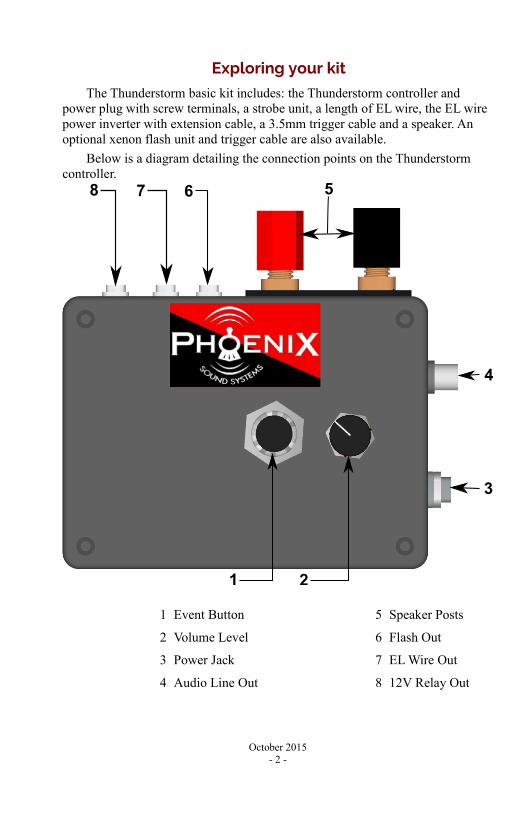
Exploring your kit
The Thunderstorm basic kit includes: the Thunderstorm controller and power plug with screw terminals, a strobe unit, a length of EL wire, the EL wire power inverter with extension cable, a 3.5mm trigger cable and a speaker. An optional xenon flash unit and trigger cable are also available.
Below is a diagram detailing the connection points on the Thunderstorm controller.
1 Event Button 5 Speaker Posts
2 Volume Level 6 Flash Out
3 Power Jack 7 EL Wire Out
4 Audio Line Out 8 12V Relay Out
October 2015- 2 -
1 2
3
4
78 6 5
Setting up the system
There are four main components, and one optional, to be installed in the space you plan on using the complete Thunderstorm system. These are the EL Wire, the LED strobe light, the flash unit (optional), a speaker and the controller itself.
The control unit should be placed in a central, easily accessible location. The controller can be powered by 12-30V DC or AC. The unit is provided with a plug and bare leads to make connection to an existing transformer a simple matter.
The EL wire creates the effect of a bolt of lightning. We recommend suspending this from the ceiling in the location you wish the lightning to originate. The wire is quite flexible and may be bent, twisted and/or curved to create a shape that meets with your approval. You may mount the EL wire from either end, but be aware that only one end can have the power inverter connected. We suggest mounting the wire with the inverter connection on the ground since you would not then need to run the control line into the air or across the ceiling. Once the EL Wire is mounted, plug the connector from the wire into the matching connector on the EL Inverter, using the extension if necessary. Insert the 3.5mm plug from the inverter into the EL output of the control module.
The flash screws into one of the supplied lamp sockets which can then be plugged into a standard 120V household power outlet. If you prefer, the flash unit can be screwed into any standard medium screw base light fixture. Next, using one of the included 3.5mm cables, plug one end into the jack on the side of the flash near the red trigger button; the other end plugs into the flash output jack on the Thunderstorm module.
The strobe light includes a bracket to assist in mounting the unit. The strobe maybe hung or floor mounted as necessitated by your layout. Plug the strobe light into a standard household outlet. Connect the remaining 3.5mm cable between the 12V input of the strobe light and the 12V output of the Thunderstorm controller.
Mount the speaker in an unobtrusive location and wire it to the binding post speaker connections on the control unit.
The Phoenix Thunderstorm is equipped with a line level audio output if you wish to run the system into an external amplified system. This output makes it possible to add a subwoofer to the system and another level of realism to the rumble and crack of the thunder.
Operating the system
Once power is applied the Thunderstorm begins a random sequence which will continue as long as the system is powered. Pressing the Event Button will cause a clap of thunder and all lighting outputs to be triggered simultaneously.
October 2015- 3 -
Tips and Tricks
“The Bolt” EL Wire
In our experience the EL Wire is most effective when mounted from the ceiling as close to the background scenic element of the layout as possible. We also suggest mounting with the inverter unit on the bottom end where it will be easier to hide. When mounted in this fashion the wire more readily blends in and 'disappears' into the background when not energized.
The wire is quite flexible and can be bent, twisted and curved as desired to achieve a more realistic lightning bolt effect.
“The Flash” Xenon Flash Unit
Power for the strobe is US household standard 110-120V AC. The unit power connection is a medium screw base, typical for a common light bulb. You can screw the unit into any standard light socket overhead or plug it into a extension cord or wall outlet using the provided adapter.
For the most realistic effect the flash unit should be mounted above the display area aimed downward, this enhances the effect of the lightning flash originating from the sky. If this is not practical in the space available the unit will still provide an exciting experience if mounted low and aimed upwards.
No matter where you mount the flash be sure to place the unit out of obvious sight lines. The less obvious the origin of the flash the more realistic the impression will be.
“The Strobe” LED Strobe Light
Many of the same tips apply to the LED strobe light source as the xenon flash unit. Higher is better, hidden is recommended. Note that the strobe units has two controls on it, a power switch and a rate adjustment. Please make sure that you leave the power switch in the on position and the rate knob set to the fastest setting, this will render the most realistic effect.
Audio Line Out
The line level output of the Thunderstorm can be used in in conjunction with or in place of the speaker output. A powered subwoofer or powered speaker system can easily be connected to the line out. We have found a truly impressive experience can be achieved using a 2.1 channel (left, right & subwoofer) powered computer speaker set.
October 2015- 4 -
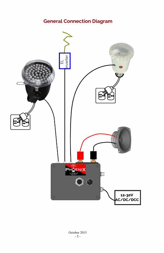
General Connection Diagram
October 2015- 5 -
Warranty
The Thunderstorm electronic system is manufactured to the highest standards using the latest assembly technology and quality, conservatively rated parts.
The materials and operation of the Thunderstorm electronic module and associated system kit components supplied by Phoenix are guaranteed to perform correctly for one year when installed and operated according to the instruction manual. In the unlikely event that your system fails, please call or email us so that we may evaluate the situation and save any unnecessary shipping. We prefer to pre-evaluate returns because frequently there is a simple explanation for any perceived problem you may be experiencing. Repairs and or replacements covered by this warranty are at no cost. However, return shipping may be charged, especially if you return your system in an engine, tender, box car or the like. A service fee may be assessed if it is determined that the failure was not due to any Phoenix supplied components.
Phoenix Sound Systems, Inc. cannot be liable for damage to the system during shipping to our facilities due to mishandling, inadequate packaging or similar circumstances beyond our control. Please be sure to package the Thunderstorm in a secure, static safe manner.
When returning your module to Phoenix for service please be sure to include your contact information (name, address and phone or email) and a brief description of the trouble. Please be specific, “Does not work” or “Just quit” does not provide any useful information and will not assist in determining what has happened and appropriate corrective actions.
Please read the handbook and any included installation notes prior to installation and operation of your system. Contact us if you have questions or are unsure about any aspect of installation or operation.
Physical modification of the module or associated components in any fashion voids this warranty. Physical modifications include but are not limited to:
• Opening the module and removing the printed circuit boards for any purpose.
• Removal, replacement or modification of any connectors or individual component pieces.
October 2015- 6 -