Chromalox 3.47 34 14.3 102.5 2-50 2-50 50 2-17 CES-48 4.69 46 14.3 138.7 1-40 1-30 1-40 1-12 ......
20
3 Phase Voltages* Output Quantity and Rating No./kW Elec at of Contactors of Rating Cap. Vol. 212˚F Heating Model (BHP) (kW) (Gals.) (Lbs./Hr.) 208 240 480† Elements Type CES — 0-100 PSIG CES-6 .6 6 6 18 30 30 30 1-6 CES-9 .9 9 6 27 30 30 30 1-9 CES-12 1.22 12 6 36.2 40 30 30 1-12 CES-18 1.73 17 6 51.2 50 50 30 1-17 CES-24 2.45 24 14.3 72.3 2-40 2-30 2-30 2-12 1-40 1-40 1-12 CES-30 2.95 29 14.3 87.4 1-50 1-30 40 1-17 CES-36 3.47 34 14.3 102.5 2-50 2-50 50 2-17 1-40 1-30 1-40 1-12 CES-48 4.69 46 14.3 138.7 2-50 2-50 1-30 2-17 2-50 2-30 2-12 CES-60 5.91 58 14.3 174.8 2-40 2-50 2-40 2-17 CES-72 6.93 68 14.3 205 4-50 4-50 2-50 4-17 CES-100 10.40 102 27.8 307 6-50 6-50 3-50 6-17 CES-135 13.9 136 30.5 410 — 8-50 4-50 8-17 1-30 CES-160 16.1 157.5 30.5 475 — 7-60 3-60 7-22.5 CES-180 18.4 180 30.5 543 — 8-60 4-60 8-22.5 Chromalox ® DIVISION 4 SECTION CES SALES REFERENCE DATE SERVICE REFERENCE Installation, Operation and RENEWAL PARTS IDENTIFICATION PQ444-1 MAY, 1999 (Supersedes PQ444) 161-562789-002 © 2010 Chromalox, Inc. Type CES-6 through CES-180 Electric Steam Boiler Standard Trim is 100 PSI — 0-90 Operating Pressure Range Boiler Serial Number . . . . . . . . . . . . . . . . . . . . . . . . . . . . . . . . Power Circuit Voltage . . . . . . . . . . . . . . . . . . . . . . . . . . . . . . . . . . Model . . . . . . . . . . . . . . . . . . . . . . . . . . . . . . . . . . . . . . . . . . . Control Circuit Voltage . . . . . . . . . . . . . . . . . . . . . . . . . . . . . . . . . National Board No. . . . . . . . . . . . . . . . . . . . . . . . . . . . . . . . . . Amps . . . . . . . . . . . . . . . Phase . . . . . . . . . . . Cy . . . . . . . . . . Important — This data file contains the National Board Registration Certificate for your boiler. It must be kept near the boiler at all times. * Single phase available up to and including 24 kW capacity. † All boilers must have separate 120V Control Circuit or Transformer. Boilers under 40 amps max are not fused.
Transcript of Chromalox 3.47 34 14.3 102.5 2-50 2-50 50 2-17 CES-48 4.69 46 14.3 138.7 1-40 1-30 1-40 1-12 ......

3 Phase Voltages*Output Quantity and Rating No./kW
Elec at of Contactors ofRating Cap. Vol. 212˚F Heating
Model (BHP) (kW) (Gals.) (Lbs./Hr.) 208 240 480† ElementsType CES — 0-100 PSIG
CES-6 .6 6 6 18 30 30 30 1-6CES-9 .9 9 6 27 30 30 30 1-9CES-12 1.22 12 6 36.2 40 30 30 1-12CES-18 1.73 17 6 51.2 50 50 30 1-17CES-24 2.45 24 14.3 72.3 2-40 2-30 2-30 2-12
1-40 1-40 1-12CES-30 2.95 29 14.3 87.4 1-50 1-30 40 1-17CES-36 3.47 34 14.3 102.5 2-50 2-50 50 2-17
1-40 1-30 1-40 1-12CES-48 4.69 46 14.3 138.7 2-50 2-50 1-30 2-172-50 2-30 2-12CES-60 5.91 58 14.3 174.8 2-40 2-50 2-40 2-17
CES-72 6.93 68 14.3 205 4-50 4-50 2-50 4-17CES-100 10.40 102 27.8 307 6-50 6-50 3-50 6-17CES-135 13.9 136 30.5 410 — 8-50 4-50 8-17
1-30CES-160 16.1 157.5 30.5 475 — 7-60 3-60 7-22.5
CES-180 18.4 180 30.5 543 — 8-60 4-60 8-22.5
Chromalox®
DIVISION 4 SECTION CESSALES
REFERENCE
DATE
SERVICE REFERENCEInstallation, Operationand
RENEWAL PARTS IDENTIFICATIONPQ444-1
MAY, 1999
(Supersedes PQ444)
161-562789-002
© 2010 Chromalox, Inc.
Type CES-6 through CES-180 Electric Steam BoilerStandard Trim is 100 PSI — 0-90 Operating Pressure Range
Boiler Serial Number . . . . . . . . . . . . . . . . . . . . . . . . . . . . . . . . Power Circuit Voltage . . . . . . . . . . . . . . . . . . . . . . . . . . . . . . . . . .
Model . . . . . . . . . . . . . . . . . . . . . . . . . . . . . . . . . . . . . . . . . . . Control Circuit Voltage . . . . . . . . . . . . . . . . . . . . . . . . . . . . . . . . .
National Board No. . . . . . . . . . . . . . . . . . . . . . . . . . . . . . . . . . Amps . . . . . . . . . . . . . . . Phase . . . . . . . . . . . Cy . . . . . . . . . .
Important — This data file contains the National Board Registration Certificate for your boiler. It must be kept near the boiler at all times.
* Single phase available up to and including 24 kW capacity.† All boilers must have separate 120V Control Circuit or Transformer.Boilers under 40 amps max are not fused.

MODEL CES-24 through CES-180
MODEL CES-6 through CES-18
DIMENSIONS
DrainBlowdownValve K
A C
H
B
D EF
G
Check ValveL
OptionalTransformer
Safety ValveOutletJManual ResetHigh Limit ControlOptional VacuumBreaker
McDonnell & MillerLow Water CutoffPump Control
Drain BlowdownValve
OperatingPressureControl
Control CircuitOn-Off Switchwith Pilot Light
1-1/4"
7/16" Bolt Hole (typical)
Pump/SolenoidConnectionConduit Box
Element
I Steam Outlet
Sight Glass
ElementAccess Door
5/8"
7/16" Bolt Hole (typical)
DrainBlowdownValve K
A
B
C
Check Valve
D
H
FE
G
OperatingPressureControl
Safety ValveOutletManual ResetHigh Limit ControlOptional VacuumBreaker
McDonnell & MillerLow Water CutoffPump Control
Drain BlowdownValve
1-1/4"
7/16" Bolt Hole (typical)
Control CircuitOn-Off Switchwith Pilot Light
OptionalTransformer
I Steam Outlet
Sight Glass
ElementAccess DoorElement
5/8"
7/16" Bolt Hole (typical)
Pump/SolenoidConnectionConduit Box
Control PanelStandard when Three (3)or more Contactors are used
L
2
Typical Plumbing Installation of a Steam Boiler with Condensate Return System
CES — Dimensions (In.)
DIMENSIONS
INSTALLATION
Model A B* C D E F G H I J K LCES-6 37 22-1/2 30 15-1/4 20 30-1/2 9-1/2 16 1/2 1 1/2 1/2
CES-9 37 22-1/2 30 15-1/4 20 30-1/2 9-1/2 16 1/2 1 1/2 1/2
CES-12 37 22-1/2 30 15-1/4 20 30-1/2 9-1/2 16 1/2 1 1/2 1/2
CES-18 37 22-1/2 30 15-1/4 20 30-1/2 9-1/2 16 1/2 1 1/2 1/2
CES-24 43-1/2 26 46 17-1/2 23 34-1/2 16-1/2 24-1/2 1 1 1 3/4
CES-30 43-1/2 26 46 17-1/2 23 34-1/2 16-1/2 24-1/2 1 1 1 3/4
CES-36 43-1/2 26 46 17-1/2 23 34-1/2 16-1/2 24-1/2 1 1 1 3/4
CES — Dimensions (In.)Model A B* C D E F G H I J K LCES-48 43-1/2 26 46 17-1/2 23 34-1/2 16-1/2 24-1/2 1 1 1 3/4
CES-60 43-1/2 26 46 17-1/2 23 34-1/2 16-1/2 24-1/2 1 1 1 3/4
CES-72 43-1/2 26 46 17-1/2 23 34-1/2 16-1/2 24-1/2 1 1 1 3/4
CES-100 63-1/2 30 55 21 27 36 16-3/4 37-1/2 1-1/2 1-1/4 1 3/4
CES-135 63-1/2 32 55 20-1/2 26 37-1/2 16 37-1/2 2 1-1/4 1 3/4
CES-160 63-1/2 32 55 20-1/2 26 37-1/2 16 37-1/2 2 1-1/4 1 3/4
CES-180 63-1/2 32 55 20-1/2 26 37-1/2 16 37-1/2 2 1-1/4 1 3/4
Note: When installing boiler, allow sufficient room (21” minimum) tofacilitate removal of elements if and when necessary.1. The boiler should be mounted on a solid level foundation.2. WARNING: A minimum distance of 18” between
boiler and any combustible material must be main-tained.
3. Complete all piping to boiler. Connect water line to tagged fittingon the motor and pump assembly, if used, or to tagged fitting onwater control feeder.
4. When any type of feed other than a pump feed is used — the exist-ing water supply must be 10 pounds greater than the boiler operat-ing pressure to assure water supply maintains proper water level inboiler. Otherwise, lack of water can cause heater failure. Keep feedwater line valves open at all times except during blowdown.
5. All water feed systems are connected to water inlet check valve.6. Connect steam line (with Globe valve) to boiler steam outlet.
Valve should be placed as close as possible to boiler outlet andsized per label on boiler.
7. To insure maximum efficiency of supplied kW, all piping fromoutlet should be insulated.
8. Drain and relief valve piping should be in accordance with stateand local codes. Floor drain to be provided directly below unit.
9. All electrical wiring should be done by licensed electrician inaccordance with national and local electrical codes.
10. If pump is located less than 30 feet from boiler, a secondcheck valve is required.
VacuumBreaker
SafetyValve
Drain
Boiler
CheckValve
CheckValve
CheckValve
GlobeValve
GateValve
HeatExchangerWater/Steam
Separator
Insulated Steam Lines(Pitch Down 5˚)
Pitch Down 5˚Vent
CondensateReturn
Drain
GateValve
Strainer
Return
Cold WaterMake-Up
CentrifugalTurbine Pump
Steam
Water
Condensate
Vapor
(TypicalLoad)
TrapTrap
3
*Add two inches for transformer.

Diagram 1
3 Phase Voltage 3 Phase Voltage 3 Phase VoltageBoiler 208 240 480 Boiler 208 240 480 Boiler 208 240 480
WIRING
TYPICAL WIRING DIAGRAMS
WARNING: Hazard of Electric Shock. Boiler must besuitably grounded according to N.E.C. standard.1. Be sure to use the proper wire. Electric wiring to boiler should be
in accordance with National Electrical Code or local wiring codefollowing wiring diagram supplied. (See recommendations onsafety switches and fusing.)
2. The unit is completely wired and pre-tested before shipment. Nointernal wiring is required.If a separate control circuit is used, the control circuit should beconnected to the control terminal block, inside access door (notrequired with transformer).
3. Safety Switches — WARNING: Purchaser should use asafety switch employing circuit breakers or fusesbetween his main power source and the boiler.
4. Because of their water lines, boilers are susceptible to lightningdamage. Industrial type lightning protectors should be installed permanufacturer’s recommendations at your service entrance. Check
your contractor or electrical dealer for recommended type for yoursystem.
5. Be sure all electrical connections are sufficiently tightened.6. WARNING: Substitution of components or modifica-
tion of wiring system voids the warranty and maylead to dangerous operating conditions.
7. SPECIAL INSTRUCTIONS FOR CUSTOMERS SUPPLY-ING THEIR OWN CONDENSATE OR PUMP SYSTEMS.A. Check the voltage of the motor before making the wiring con-
nection. Some Chromalox boilers are supplied with dual volt-age systems. The motor should always match the voltage of thecontrol circuit.
B. The motor circuit should be wired into the pump control asshown in wiring diagram (float type pump control). If boiler isequipped with solid state pump control, refer to wiring diagramand use terminals 5 and 2.
Use Applicable wiring diagrams based on model number and power voltage.
CES-6 1 1 1 CES-30 2 2 3 CES-100 8 8 9CES-9 1 1 1 CES-36 2 2 3 CES-135 10 11CES-12 1 1 1 CES-48 4 4 5 CES-160 12 13CES-18 1 1 1 CES-60 6 6 7 CES-180 10 11CES-24 2 2 3 CES-72 6 6 7 Export 14
2PS
BR
HeaterContactors
Feed Water
Boiler On
3GND
BFU6
B 1PB
Off
1GND
1GND1 HTR C1
FU1
FU2
FU3
FU5FU4
H1 H2
X1 X3
L3
1L1
1L3
1L2
L2L1
X2 X4
Optional Transformer
1
1
C1
2
2
C4
C3
C2
R
1LT
Y
On
IFS
O 1PS O O
W
Feed WaterElectrical
Connection
21
1TB
1 2 33GND
1GND
2GND
1HTR
FU6
FU
1PB
Cabinet Exterior Left Side Cabinet Exterior Right SidePanel Layout
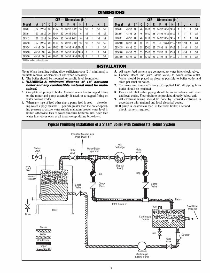
Wire Color CodeB = BlackBR = BrownR = RedO = OrangeY = YellowG = GreenBL = BlueW = White
* Boilers under 40 Amps total (not fused)
4
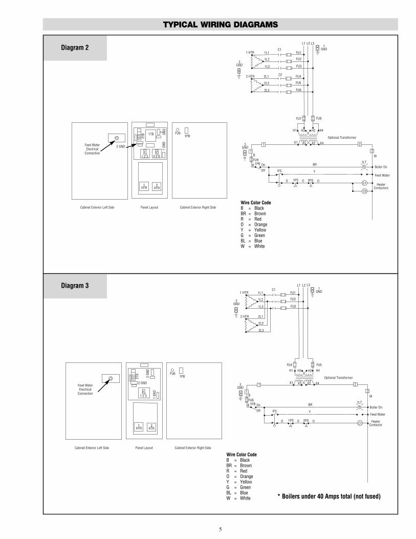
Diagram 2
TYPICAL WIRING DIAGRAMS
2PS
BR
HeaterContactors
Feed Water
Boiler On
3GND
BFU9
B 1PB
Off
2GND
1GND
1 HTRC1
FU1
FU2
FU3
FU8FU7
H1 H2
X1 X3
L3
1L1
1L3
1L2
L2L1
X2 X4
Optional Transformer
1
1
C1
2
2
C2
R
1LT
Y
On
IFS
O 1PS O O
W
Feed WaterElectrical
Connection
21 2T
B2 GND
1HTR
FU91PB
Cabinet Exterior Left Side Cabinet Exterior Right SidePanel Layout
2HTR
C1FU
1 2 3
C2FU
4 2 6
1TB
1 GN
D3
GND H4H3
2 HTR C2 FU4
FU5
FU6
2L1
2L3
2L2
Wire Color CodeB = BlackBR = BrownR = RedO = OrangeY = YellowG = GreenBL = BlueW = White
Diagram 3
2PS
BR
HeaterContactor
Feed Water
Boiler On
3GND
BFU6
B 1PB
Off
1GND1 HTR
C1FU1
FU2
FU3
FU5FU4
H1 H2
X1 X3
L3
1L1
1L3
1L2
L2L1
X2 X4
Optional Transformer
1
1
C1
2
2
R
1LT
Y
On
IFS
O 1PS O O
W
Feed WaterElectrical
Connection
21 2T
B
2 GND
1HTR
FU61PB
Cabinet Exterior Left Side Cabinet Exterior Right SidePanel Layout
2HTR
C1FU
1 2 3 1 GN
D
3 GN
D H4H3
2 HTR 2L1
2L3
2L2
2GND
Wire Color CodeB = BlackBR = BrownR = RedO = OrangeY = YellowG = GreenBL = BlueW = White * Boilers under 40 Amps total (not fused)
5

Diagram 4
TYPICAL WIRING DIAGRAMS
2PS
BR
HeaterContactor
Feed Water
Boiler On
3GND
BFU12
B 1PB
Off
2GND
1GND
1 HTRC1
FU1
FU2
FU3
FU11FU10
H1 H2
X1 X3
L3
1L1
1L3
1L2
L2L1
X2 X4Optional Transformer
1
1
C1
2
2
C2
R
1LT
Y
On
IFS
O 1PS O O
W
Feed WaterElectrical
Connection
21 2T
B
2 GND
1 GND
2 GND
1HTR
FU121PB
Cabinet Exterior Left Side Cabinet Exterior Right SidePanel Layout
2HTR
3Htr
1TB
3 G
ND
H4H3
2 HTR C2 FU4
FU5
FU6
2L1
2L3
2L2
FU1 2 3
FU4 5 6
FU7 8 9
C1 C3C2
FU7
FU8
FU9
C3 3L1
1L3
3L2
3 HTR
C3Heater
Contactor
Wire Color CodeB = BlackBR = BrownR = RedO = OrangeY = YellowG = GreenBL = BlueW = White
Diagram 5
2PS
BR
HeaterContactors
Feed Water
Boiler On
3GND
BFU9
B 1PB
Off
2GND
1GND
1 HTRC1
FU1
FU2
FU3
FU8FU7
H1H2
X1 X3
L3
1L1
1L3
1L2
L2L1
X2 X4
Optional Transformer
1
1
C1
2
2
C2
R
1LT
Y
On
IFS
O 1PS O O
WFeed WaterElectrical
Connection
21 2T
B
2 GND
1HTR
FU91PB
Cabinet Exterior Left Side Cabinet Exterior Right SidePanel Layout
2HTR
C2FU
4 5 6
1TB
1 GN
D3
GND
H4H3
2 HTR C2 FU4
FU5
FU6
2L1
2L3
2L2
C1FU
1 2 3
3HTR
3 HTR 3L1
3L3
3L2
Wire Color CodeB = BlackBR = BrownR = RedO = OrangeY = YellowG = GreenBL = BlueW = White
6
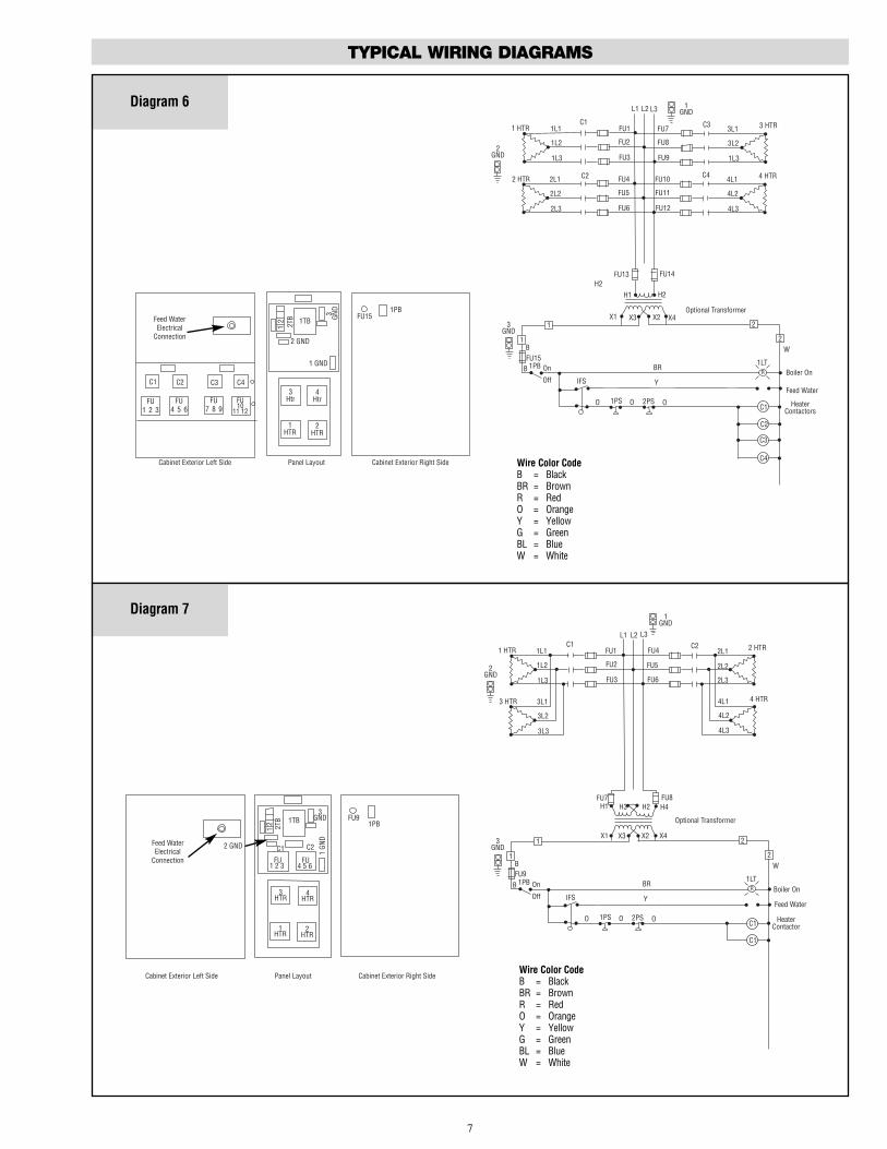
Diagram 6
TYPICAL WIRING DIAGRAMS
2PS
BR
HeaterContactors
Feed Water
Boiler On
3GND
BFU15
B 1PB
Off
2GND
1GND
1 HTRC1
FU1
FU2
FU3
FU14FU13
H1H2
X1 X3
L3
1L1
1L3
1L2
L2L1
X2 X4Optional Transformer
1
1
C1
2
2
C2
R
1LT
Y
On
IFS
O 1PS O O
W
Feed WaterElectrical
Connection
21 2T
B
1 GND
2 GND
1HTR
FU151PB
Cabinet Exterior Left Side Cabinet Exterior Right SidePanel Layout
2HTR
3Htr
1TB3
GND
H2
2 HTR C2 FU4
FU5
FU6
2L1
2L3
2L2
FU1 2 3
FU4 5 6
FU7 8 9
C1 C3C2
FU7
FU8
FU9
C3 3L1
1L3
3L2
3 HTR
C3
C4
FU10
11 12
4Htr
FU10
FU11
FU12
C4 4L1
4L3
4L2
4 HTR
C4Wire Color CodeB = BlackBR = BrownR = RedO = OrangeY = YellowG = GreenBL = BlueW = White
Diagram 7
2PS
BR
HeaterContactor
Feed Water
Boiler On
3GND
BFU9
B 1PB
Off
1GND
1 HTRC1
FU1
FU2
FU3
FU8FU7H1 H2
X1 X3
L3
1L1
1L3
1L2
L2L1
X2 X4
Optional Transformer
1
1
C1
2
2
R
1LT
Y
On
IFS
O 1PS O O
W
Feed WaterElectrical
Connection
21 2T
B
2 GND
1HTR
FU91PB
Cabinet Exterior Left Side Cabinet Exterior Right SidePanel Layout
2HTR
FU1 2 3
1 GN
D
3GND
H4H3
3 HTR 3L1
3L3
3L2
2GND
3HTR
4HTR
C1 C2
FU4 5 6
1TB
C1
2 HTRFU4
FU5
FU6
2L1
2L3
2L2
4 HTR4L1
4L3
4L2
C2
Wire Color CodeB = BlackBR = BrownR = RedO = OrangeY = YellowG = GreenBL = BlueW = White
7

Diagram 8
TYPICAL WIRING DIAGRAMS
FU1 2 3
FU4 5 6
FU7 8 9
C1 C3C2
C4
FU10
11 12
C5
FU13
14 15
C6
FU16
17 18
5HTR
4HTR
3HTR
6HTR
2HTR
1HTR
122T
B
1TB
3 GND2
GND
1 GND
FU211PB
3GND
C1
C2
C6
C5
C4
C3
2PS
3PS1PS
On
Off
FU21
IFS
O O O
Y
BR
B
B1PB
1
1 2
2
W
R BoilerOn
Feed Water
Heater Contactor
Heater Contactor
Heater Contactor
Heater Contactor
Heater Contactor
Heater Contactor
1LT
Optional TransformerX1 X4X2X3
FU19 FU20
2 HTR
3 HTR
1 HTR 1L1
1L31L2
2L1
2L32L2
3L1
3L33L2
4 HTR 4L1
4L34L2
C1
C4
C3
C2
FU1
FU18FU17FU16
FU15FU14FU13
FU12FU11FU10
FU9FU8FU7
FU6FU5FU4
FU3FU2
C6
C5 5 HTR
6 HTR
5L1
6L36L26L1
5L35L2
L1 L3L21
GND
2GND
Cabinet Exterior Left Side Cabinet Exterior Right SidePanel Layout
Feed WaterElectrical
Connection
Wire Color CodeB = BlackBR = BrownR = RedO = OrangeY = YellowG = GreenBL = BlueW = White
Diagram 9
FU1 2 3
FU4 5 6
FU7 8 9
C1 C3C2
5HTR
4HTR
3HTR
6HTR
2HTR
1HTR
122T
B
1TB
3 GND
2GND
1 GND FU121PB
3GND
C1
C2
C3
3PS1PS
On
Off
FU12
IFS
O O O
Y
BR
B
B1PB
1
1 2
2
W
R BoilerOn
Feed Water
Heater Contactor
Heater Contactor
Heater Contactor
1LT
Optional Transformer
X1 X4X2X3
C1
C2
FU1
FU9FU8FU7
FU6FU5FU4
FU3FU2
C3 5 HTR
6 HTR
5L1
6L36L26L1
5L35L2
1GND
Cabinet Exterior Left Side Cabinet Exterior Right SidePanel Layout
Feed WaterElectrical
Connection
2PS
H1 H4H2H3
FU10 FU11
2 HTR
3 HTR
1 HTR 1L1
1L3
1L2
2L1
2L32L2
3L1
3L3
3L2
4 HTR 4L1
4L34L2
2GND
L1 L2 L3
Wire Color CodeB = BlackBR = BrownR = RedO = OrangeY = YellowG = GreenBL = BlueW = White
8

Diagram 10
TYPICAL WIRING DIAGRAMS
1314 15
1617 18
1920 21
C5 C7C6
C1
1 2 3
C2
4 5 6
C3
7 8 9
5HTR
4HTR
3HTR
6HTR
2HTR
1HTR
122T
B
1TB
3 GND2
GND
1 GND
FU271PB
3GND
C1
C2
C6
C3
2PS
3PS1PS
On
Off
FU27
IFS
O O O
Y
BR
B
B1PB
1
1 2
2
W
R BoilerOn
Feed Water
Heater Contactor
1LT
Optional Transformer
X1 X4X2X3
FU25 FU26
2 HTR
3 HTR
1 HTR 1L1
1L31L2
2L1
2L32L2
3L1
3L33L2
4 HTR 4L1
4L34L2
C1
C4
C3
C2
FU1
FU18FU17FU16
FU15FU14FU13
FU12FU11FU10
FU9FU8FU7
FU6FU5FU4
FU3FU2
C6
C5 5 HTR
6 HTR
5L1
6L36L26L1
5L35L2
L1 L3L21
GND
2GND
Cabinet Exterior Left Side Cabinet Exterior Right SidePanel Layout
Feed WaterElectrical
Connection
2223 24
C4
7HTR
8HTR
1011 12
C8
C8
C4
Heater Contactor
H1 H4H2H3
FU24FU23FU22
FU21FU20FU13
C8
C7 7 HTR
6 HTR
7L1
8L38L28L1
5L37L2
C5
C7
Wire Color CodeB = BlackBR = BrownR = RedO = OrangeY = YellowG = GreenBL = BlueW = White
Diagram 11
FU1 2 3
FU4 5 6
FU7 8 9
C1 C3C2
5HTR
4HTR
3HTR
6HTR
2HTR
1HTR
122T
B
1TB
3 GND
2GND
1 GND FU151PB
3GND
C1
C2
C3
3PS1PS
On
Off
FU15
IFS
O O O
Y
BR
B
B1PB
1
1 2
2
W
R BoilerOn
Feed Water
Heater Contactor
Heater Contactor
1LT
Optional Transformer
X1 X4X2X3
C1
C2
FU1
FU9FU8FU7
FU6FU5FU4
FU3FU2
C3 5 HTR
6 HTR
5L1
6L36L26L1
5L35L2
1GND
Cabinet Exterior Left Side Cabinet Exterior Right SidePanel Layout
Feed WaterElectrical
Connection
2PS
H1 H4H2H3
FU13 FU14
2 HTR
3 HTR
1 HTR 1L1
1L3
1L2
2L1
2L32L2
3L1
3L3
3L2
4 HTR 4L1
4L34L2
2GND
L1 L2 L3
FU10
11 12
C4
7HTR 8HTR
C4
FU12FU11FU10 C4 7 HTR
8 HTR
5L1
8L38L28L1
5L37L2
Wire Color CodeB = BlackBR = BrownR = RedO = OrangeY = YellowG = GreenBL = BlueW = White
9

Diagram 12
TYPICAL WIRING DIAGRAMS
1314 15
1617 18
1920 21
C5 C7C6
C1
1 2 3
C2
4 5 6
C3
7 8 9
5HTR
4HTR
3HTR
6HTR
2HTR
1HTR
122T
B
1TB
3 GND
2GND
1 GND
FU241PB
3GND
C1
C2
C5
C3
2PS
3PS1PS
On
Off
FU24
IFS
O O O
Y
BR
B
B1PB
1
1 2
2
W
R BoilerOn
Feed Water
Heater Contactor
1LT
Optional TransformerX1 X4X2X3
FU22 FU23
2 HTR
3 HTR
1 HTR 1L1
1L31L2
2L1
2L32L2
3L1
3L33L2
4 HTR 4L1
4L34L2
C1
C4
C3
C2
FU1
FU18FU17FU16
FU15FU14FU13
FU12FU11FU10
FU9FU8FU7
FU6FU5FU4
FU3FU2
C6
C5 5 HTR
6 HTR
5L1
6L36L26L1
5L35L2
L1 L3L21
GND
2GND
Cabinet Exterior Left Side Cabinet Exterior Right SidePanel Layout
Feed WaterElectrical
Connection
C4
7HTR
FU10
11 12
C4
Heater Contactor
H1 H4H2H3
FU21FU20FU19 C7 7 HTR7L1
5L37L2
FU FU FU
C7
C6
Heater Contactor
Heater Contactor
Heater Contactor
Heater Contactor
Heater Contactor
Wire Color CodeB = BlackBR = BrownR = RedO = OrangeY = YellowG = GreenBL = BlueW = White
Diagram 13
FU1 2 3
FU4 5 6
FU7 8 9
C1 C4C2
5HTR
4HTR
3HTR
6HTR
2HTR
1HTR
122T
B
1TB
3 GND
2GND
1 GND
FU151PB
3GND
C1
C2
C32PS
3PS1PS
On
Off
FU15
IFS
O O O
Y
BR
B
B1PB
1
1 2
2
W
R BoilerOn
Feed Water
Heater Contactor
1LT
Optional TransformerX1 X4X2X3
FU13 FU14
2 HTR
3 HTR
1 HTR 1L1
1L31L2
2L1
2L32L2
3L1
3L33L2
4 HTR 4L1
4L34L2
C1
C2
FU1
FU9FU8FU7
FU6FU5FU4
FU3FU2
C3 5 HTR
6 HTR
5L1
6L36L26L1
5L35L2
L1 L3L21
GND
2GND
Cabinet Exterior Left Side Cabinet Exterior Right SidePanel Layout
Feed WaterElectrical
Connection
7HTR
FU10
11 12
C4
Heater Contactor
H1 H4H3H2
FU12FU11FU10 C4 7 HTR7L1
5L37L2
Heater Contactor
Heater Contactor
C3
Wire Color CodeB = BlackBR = BrownR = RedO = OrangeY = YellowG = GreenBL = BlueW = White
10
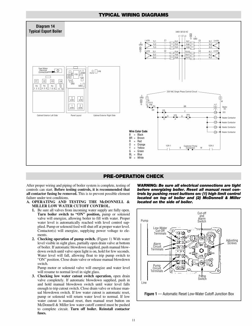
After proper wiring and piping of boiler system is complete, testing ofcontrols can start. Before testing controls, it is recommended thatall contactor fusing be removed. This is to prevent possible elementfailure under test conditions.A. OPERATING AND TESTING THE McDONNELL &
MILLER LOW WATER CUTOFF CONTROL.1. Be sure all valves from incoming water supply are fully open.
Turn boiler switch to “ON” position, pump or solenoidvalve will energize, allowing boiler to fill with water. Properwater level is automatically reached with level control sup-plied. Pump or solenoid feed will shut off at proper water level.Contactor(s) will energize, supplying power voltage to ele-ments.
2. Checking operation of pump switch. (Figure 1) With waterlevel visible in sight glass, partially open drain valve at bottomof boiler. If automatic blowdown supplied, push manual blow-down switch until valve open light is on, hold for few seconds.Water level will fall, allowing float to trip pump switch to“ON” position. Close drain valve or release manual blowdownswitch.Pump motor or solenoid valve will energize and water levelwill resume to normal level in sight glass.
3. Checking low water cutout switch operation, open drainvalve completely. If automatic blowdown supplied, push inand hold manual blowdown switch until water level fallsenough to trip cutout switch. Close drain valve or release man-ual blowdown switch. If low water cutout is automatic reset,pump or solenoid will return water level to normal. If lowwater cutout is manual reset, then manual reset button onMcDonnell & Miller low water cutoff control must be pushedto complete circuit. Turn off boiler. Reinstall contactorfuses.
WARNING: Be sure all electrical connections are tightbefore energizing boiler. Reset all manual reset con-trols by pushing reset buttons on: (1) high limit controllocated on top of boiler and (2) McDonnell & Millerlocated on the side of boiler.
Diagram 14Typical Export Boiler
TYPICAL WIRING DIAGRAMS
C1
CR
C2
C3
2PS1PS
On
Off
FU13
IFS
O O
Y
BR
B
B1PB
1 2
W
R BoilerOn
9.9
Heater Contactor
1LT
2 HTR
1 HTR 1L1
1L31L2
2L1
2L32L2
C1
C2
FU1
FU9FU8FU7
FU6FU5FU4
FU3FU2
C3 3 HTR3L1
3L33L2
L1 L3L2
Heater Contactor
FU12FU11FU10 C4 4 HTR4L1
4L34L2
Heater Contactor
Heater Contactor
346V 3Ø 50 HZ
220 VAC Single Phase Control Circuit
1
C4
1CR-1B W
1CR-2Customer PumpConnection
FU1 2 3
FU4 5 6
FU7 8 9
C1 C4C2
3HTR
2HTR
1HTR
4HTR
12 2T
B1TB
3 GND
2GND 1
GND
FU131PB
Cabinet Exterior Left Side Cabinet Exterior Right SidePanel Layout
Feed WaterElectrical
Connection
FU10
11 12
C3
1CR
3GND
1GND
2GND
Wire Color CodeB = BlackBR = BrownR = RedO = OrangeY = YellowG = GreenBL = BlueW = White
11
AC D
B
Line
Pump
Low-WaterCut-Off
Terminals
AlarmCircuit
Terminals
PumpCircuit
Terminals
PumpSwitch
Cut-offand
AlarmSwitch
AdjustingScrews
Figure 1 — Automatic Reset Low-Water Cutoff Junction Box
PRE-OPERATION CHECK

ADJUSTING OPERATING PRESSURE CONTROLS1. Chromalox boilers are supplied with operating and high limit pres-
sure controls. One is used for controlling the operating pressure ofthe boiler while the other is used as a high limit control. To deter-mine the difference in the controls, the high limit has a manual resetlever on top of the case. Also, there is no differential scale present.
2. On all controls, the pressure adjusting screw on the top of the casesets the desired pressure. Turning the screw counterclockwisereduces the pressure setting (CUT OUT) (See Figure 2). High limitcontrol should be set at 10 psig above the operating pressure of theboiler.
3. The differential adjusting screw on the operating control is set in thesame manner as the pressure adjusting screw. The CUT OUT set-ting minus the differential setting, equals CUT IN pressure of theoperating control.
To check operation of the controls, close steam outlet valve and adjustoperating pressure control to a low pressure setting. Also, set high limitcontrol at 10 psig above operating pressure control. Turn on boiler, andallow pressure to build up. When pressure gauge reading approachesset point of pressure control, the switch will trip and shut off boiler.Turn off boiler.
To reset pressure control, bleed off enough pressure in the boiler byopening steam outlet drain, or blowdown valve to allow the operatingcontrol to reset.4. HIGH LIMIT PRESSURE CONTROL OPERATION
The high limit is tested in the same manner but with the operatingcontrol set above the pressure setting of the high limit. (Figure 3)CAUTION: This is for test purposes only!When the high limit trips, turn off boiler and reset high limit toproper setting. The manual reset level must be pushed to resumeoperation upon startup.
Differential Adjusting Screw
Pressure Adjusting Screw
Terminal 1 Open onPressure Rise
Terminal 2Common
DifferentialSettingIndicator
PressureSettingIndicator
PressureAdjustingScrew
Terminal 1 Open onPressure Rise
Terminal 2CommonCutout
PressureIndicator
Manual Reset Lever
CES-12 through CES-72, one pressure control supplied; CES-100 through CES-180, two pressure controls supplied.
Figure 2
Figure 1
12
OPERATION
OPERATION
RECOMMENDED START-UP PROCEDURES1. Close globe valve on steam outlet side of boiler. (Customer Supplied)2. Turn on boiler and allow pressure to build up to operating pressure.3. Only open globe valve at quarter turns at first, introducing smaller
amounts of steam into process. Avoid opening globe valve all atonce. This will eliminate the possibility of evacuating the boiler ofwater caused by the suddenly increased boiling of the water in thevessel as the pressure is reduced. On boilers where constant pres-sure is not maintained, globe valve should be kept partially closed.This will maintain a constant head on the boiler and stabilize anyfluctuation in boiler water level.
Note: For best boiler performance, a 1/4” less steam valve than size of safety valve should be plumbed as close as practi-cable to steam outlet. Where 1/2” safety valve is used on boil-er, a 1/4” steam valve is recommended.
MANUAL BLOWDOWN INSTRUCTIONSBlowdown is an essential part of boiler operation. It is the best
preventative maintenance you can give your boiler and will addyears of life to the unit. Make sure a blowdown schedule is estab-lished and followed regularly.
In extremely hard water areas, blowdown is necessary once aday. In soft water areas, once each week. If there is a particularproblem which applies to your own local water condition other
than mineral content, take this into consideration in determiningwhich schedule is to be followed.1. At end of the working day, while boiler is still operating, turn
switch to the OFF position and close water supply valve. De-ener-gize wall mounted safety switch.
2. If blowing-down into a receptacle, allow pressure to decrease to15-20 psi before opening blowdown valve.
3. It is preferable to connect the blowdown valve directly into adrainage system. If this is done, the boiler can be discharged atoperating pressure.
4. When discharge is complete and boiler is drained — (a) close theblowdown valve; (b) open water supply valve; (c) put boiler switchin the ON position; and, (d) close wall mounted safety switch.
5. When refilling is complete, turn off the boiler switch unless furtheroperation is desirable.
6. If you have been supplied with a Manual Reset Low Water controlas required in some states, the reset button on the control must bepushed before boiler will begin developing pressure. (Do not pushreset until boiler has filled with water.)
The use of chemical boiler cleaning compounds in these boilersvoids all warranties unless approved by manufacturer. Some com-pounds will damage copper sheathed heating elements to shortenuseful life.

OPERATION
AUTOMATIC BLOWDOWN INSTRUCTIONS(IF FURNISHED)
The Automatic Blowdown is a device which automatically startsup your boiler in the morning; shuts it down at night and blows down(partially drains) the main boiler drain and the low water cut-off col-umn for a predetermined time interval each working day.
The heart of the unit is an electrically operated straight throughtype ball valve. It is specially designed to handle dirty, corrosive flu-ids and particles without requiring cleaning or the use of a strainer.
Both the valve and the boiler are controlled by an electric controlunit which indicates with pilot lights when the drain valve is in theopened or closed position and when the boiler is ON or OFF. In addi-tion to the automatic control function, the unit has a push button whichmomentarily de-energizes the boiler and opens the drain valve regard-less of the time of day.
The unit may also be used to blow down boilers which run con-tinuously, day and night.INITIAL TESTING — Set the switch marked “Programmedduty/24 Hour duty” located on the panel box to the “ON” position.
On the large timer set the “ON” tab at about 8 AM and the “OFF”tab at about 8 PM. Set the blowdown cycle dial at “O”.
Turn the large timer by hand until the “ON” tab passes the “TIMENOW” indicator so the “TIME NOW” arrow indicates 10 AM.
Energize the main feed to the “LINE TERMINALS” of the unit.The “BOILER ON” pilot light as well as the “VALVE CLOSED”light should glow.
Hold down the “DRAIN” button for about six seconds. The“BOILER ON” light should go out immediately as well as the“VALVE CLOSED” light. It takes about 4 seconds for the drain valveto open fully at which time the “DRAIN VALVE OPEN” light shouldlight. As soon as the “DRAIN” button is released the valve begins toclose. When it reaches the closed position, the “VALVE CLOSED”and the “BOILER ON” should light up again.
Now turn the wheel on the large timer until the “OFF” tab passesthe “TIME NOW” arrow. The “BOILER ON” light should go out andthe valve should begin to open. Once the “VALVE OPEN” light goeson, the valve should remain open for a few seconds and then auto-matically close. The “VALVE CLOSED” light should light and the“BOILER ON” light should remain off.
OPERATION— Set the “BOILER PROGRAMMED DUTY”switch to “BOILER ON” if the boiler is to be shut down each night.Set it to “24-HOUR DUTY” if the boiler is to remain on continuous-ly 24-hours per day (except during blowdown).
Set the tabs on the large timer for the ON and OFF times desiredfor the boiler, screw in the small black day-skip tabs if is to remain offduring the weekend, etc.
If the boiler is on 24-hour duty, set the OFF tab for the time that isdesired for blowdown. the ON tab can be ignored, but must remain ontimer.
The small time delay relay controls the time that the drain valveremains open. The time is controlled by adjusting knob markedBlowdown cycle. Counterclockwise decreases, clockwise increasesblowdown time. Time must be adjusted by trial.
13
Boiler On
Valve Open
Valve Closed
Programmed Duty
24 Hour Duty
Manual Drain
Valve Actuator
Timer
Automatic Blowdown Control Cabinet
Display View of Automatic Blowdown Control Cabinet
Terminal Block
Support
7 Day Clock
ControlRelay
Time Delay Relay
3 117210262 8Terminal Block
Component Layout
Supp
ort
Replace withAmp Fuse Only
Manual Drain
24 Hour Duty
Prorammed Duty
Valve Open
Valve Closed
Boiler On
Blowdown Cycle30's
0's 80's
Cycle Adjustment
On/Off Switch
Indicator Light
Indicator Light
Switch
PB Switch
Fuse
Valve Closed
Boiler Control(3)
Boiler On
Ball ValveControl
(5)
7-Day Timer(2.3)
Exterior Side
2
wClock3 A
1 8
1LT
2LT
3LT0 Valve Open
Blowdown Valve
Motorized
6
Y
B
2A
1A
2B
1B
BL
23
4
2
34
1
21
P
2PB
1PB
1CL
1CL
1TR
PR 1CR
G
3
B
1FU15A
7 R
B10
1CR
1TR
1
R
R8
2W
OR/
M
OBL/ R11
Wiring Diagram for Automatic Blowdown

OPTIONAL EQUIPMENT FOR STEAM BOILERS
AUXILIARY LOW WATER CUTOFFOperation
Operation of this control is accomplished by sensing a minute ACcurrent flowing between submerged contact probe in the boiler shell.
When this minute AC current is conducted through an external cir-cuit resistance up to 40,000 ohms or less, a signal of sufficient magni-tude is present to trigger the SCR and, in turn energize the controlrelay.
As the water level in the boiler drops below the level of the probe,the AC current is broken and the control relay is de-energized. Thecontrol will not energize until sufficient water is present in the boiler.Optional manual reset may require reset prior to heaters being ener-gized after level 13 brought to normal.
WARNING: Control will not work with de-ionized or de-mineralized water.
PROPORTIONING PRESSURE CONTROL FORSEQUENCER AND SCR CONTROLSTypical Operation
Pressure variations cause the bellows to expand or contract.Linkage between the bellows and the potentiometer wiper causes thewiper to move across the windings on the potentiometer. This variesthe resistance between R and B, and between R and W, causing anunbalance in the circuit connected to the controller.
A proportioning pressure control is used to regulate a motor drivenor solid state sequencer. The controller potentiometer, the feedbackpotentiometer in the motor and a balancing relay in the motor form anelectric bridge circuit. As long as the pressure of the controlled medi-um remains at the set point of the controller, the circuit is balanced;i.e., equal currents flow through both sides of the balancing relay andthe relay contacts are open. When the circuit is balanced, the motordoes not run.
If the pressure of the controlled medium rises, the wiper in the con-troller moves toward W. This unbalances the circuit so a larger current
flows through one side of the balancing relay. The “close” contacts inthe relay make, causing the motor to drive toward its closed position. Asthe motor runs, the wiper on the feedback potentiometer moves in adirection to balance the circuit. When the circuit is again in balance, thebalancing relay contacts open and the motor stops.
Similarly if the pressure of the controlled medium falls, the wiper onthe controller potentiometer moves toward B, and the “open” contactsin the balancing relay make. The motor drives towards its open positionuntil circuit balance is achieved.
The slightest change in the pressure of the controlled medium willcause a change in the number of elements energized to compensate forit, thus keeping the pressure constant. This process is called modulation.PROPORTIONAL PRESSURE CONTROL ONLY SUPPLIEDWITH SEQUENCER
Main Setting — Turn the adjustment screw until the indicator isopposite the low point of the desired throttling range. That is, if the pres-sure is to be held at a minimum of 50 psi, set the indicator at 50 psi. Thepressure will them be maintained between 50 psi and a higher pressureequal to the 50 psi plus the throttling range.THROTTLING RANGE SETTING (L91B)
After setting the indicator for the minimum pressure, turn the throt-tling range adjustment screw until the throttling range indicator points tothe desired throttling range on the scale. This scale is graduated from“min” to “F”. The value of each division varies with the scale range ofthe instrument.
PRESSURE VALUE EACHSCALE RATING DIVISION ON SCALE
0-15 psi 2.2 psi5-150 psi 3.6 psi
Pressure scale rating will vary depending on pressure control supplied.CHECKOUT
After the controller has been installed, wired, and set, it should betested with the system in operation. First allow the system to stabilize.Then observe the operation of the controller while raising and loweringits set point. Pressure should increase when the set point is raised anddecrease when the set point is lowered. Use accurate pressure testingequipment when checking out the controller. Do not rely on inexpensivegauges. The controllers are carefully calibrated at the factory.
If the motor or actuator runs the proper direction when the set pointis adjusted, it can be assumed that the controller is operating properly. Ifit runs in the wrong direction, reverse the B and W wires. Observe theaction of the motor to see if it stabilizes. If the motor is moving con-stantly, widen the proportioning range a little at a time, until the systemis stable.
14
Adjusting Screw Differential Adjusting Screw
R
W
B
(L91B)Proportioning Pressure Control used with Sequencer Control
3 3 2 2
2 26 6
2
2
1
1
LWCO ProbeAux. Low
Water Cutoff
O O
O
R H C
1PS
C1 NO
L1 L2
1PS
BL
W
Y
2PSBL
AutoBlowDown
System
BR
C1
W
W
HeaterContactor
Feed Water(Solenoid Pump)
R
1LTW
Boiler On
2GND
3GND
1GND
BFU3
B 1PB On
Off
X1 X3 X2 X4
1 HTR C1
Fuses Suppliedon Boilers RatedOver 40 Amps.
FU
FU
FU
FU2FU1
H1 H2H3 H4480V/120V
1.5 KVA
480V3
60 HZL1 L3L2
Typical Wiring forAuxiliary Low Water Cutoff
Electronic Resistance SensingAmplifier for Auxiliary
Low Water Cutoff

OPTIONAL EQUIPMENT FOR STEAM BOILERS
IF A CONTROLLER SEEMS TO OPERATE IMPROPERLYIf the controller is suspected of operating improperly, it may be
further checked as follows:1. Leave the controller installed where it is, but disconnect all power
to the boiler.2. Loosen the cover screw below the main scaleplate and remove the
cover.3. Disconnect the wires from the controller.4. Connect an ohmmeter between controller terminals B and W to
measure the resistance of the potentiometer in the controller. Theohmmeter should read about 135 ohms on an L91B.
5. Connect the ohmmeter between controller terminals W and R andraise the set point of the controller above the actual pressure beingmeasured. The ohmmeter should read the full value of the poten-tiometer measured in step 4 (135 ohms for an L91B).
6. Slowly lower the set point of the controller while observing theohmmeter reading. The resistance should drop to zero at some setpoint below the actual pressure.
7. An approximation of the proportioning range can be made byobserving the change in set point required for a resistance changefrom zero to full value.
8. When the controller is operating properly, reconnect the wires,replace the cover, tighten the cover screw, and reset the controllerto the desired value.
9. Reconnect power to the controlled motor.
BOILER SEQUENCE — SOLID STATESolid State Progressive Sequencer
The solid state progressive sequencer provides accurate elec-tronic control of multi-stage loads of the type used in Chromaloxsteam boilers. It features progressive sequencing (first on-first off)which equalizes the operating time of each load. This control givesvisual indication of each energized stage by means of integralsolid state light emitting diodes. In the event of power interrup-tion, all heating elements are immediately de-energized for safety.When power resumes, the control will restage the loads one at atime.
The solid state sequencer operates on 120V AC/60 Hz andeach output is relay switched with a load rating of 125 VA at 120VAC.
The input to the sequencer is a 0-135 OHM potentiometer sup-plied on the operating pressure control. The sequencer has a sen-sitivity control which is adjustable from min. to max. This sensi-tivity control defines the amount of resistance (pressure) deviationallowed before adding or subtracting a load. Potentiometer resis-tance should decrease with increasing pressure. Connections aremade to red and white terminals of proportional pressure control.See Wiring Diagram 337-300164-452 for Boiler With Solid StateSequencer.
Main ScaleAdjusting
ScrewProportioning Range
Adjusting Screw
RWB
Main ScaleSetting
Indicator
Set Point
Increase
RW B
Ohmmeter
Increases to135 Ohms
Terminals are not Labeled, but Screw-Heads areColor Coded Red (R), White (W) and Blue (B).
15
PressureControl
5 StepControl
Sequencer
AutoBlowdown
System
Heater Contactor
Heater Contactor
Heater Contactor
Heater Contactor
Feed WaterSolenoid Valve
BoilerOn
Optional Transformer
480/120V
480V 3Ø 60 HZ
Typical wiring for boilers equipped with Auto Blowdown System and/orSolid State Sequencer.
Solid State Sequencer
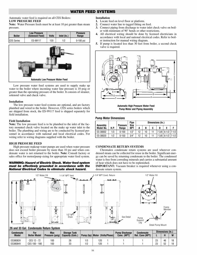
Automatic water feed is required on all CES Boilers:LOW PRESSURE FEEDNote: Water Pressure feeds must be at least 10 psi greater than steampressure.
Low pressure water feed systems are used to supply make upwater to the boiler where incoming water line pressure is 10 psig orgreater than the operating pressure of the boiler. It consists of strainer,solenoid valve and check valve.
InstallationThe low pressure water feed systems are optional, and are factory
plumbed and wired to the boiler. However, CES series boilers whichare shipped from stock, the ES-99117 feed is shipped separately forfield installation.
Field InstallationNote: The low pressure feed is to be plumbed to the inlet of the fac-tory mounted check valve located on the make up water inlet to theboiler. The plumbing and wiring are to be conducted by licensed per-sonnel in accordance with national and local electrical codes. Forwiring refer to wiring diagrams supplied with the boiler.
HIGH PRESSURE FEEDHigh pressure makeup water pumps are used when water pressure
does not exceed boiler pressure by more than 10 psi and when con-densate water is not returned to the boiler. Note: Consult factory orsales office for motor/pump sizing for appropriate water feed system.
WARNING: Hazard of Electric Shock. Water feed systemmust be effectively grounded in accordance with theNational Electrical Codes to eliminate shock hazard.
Installation1. Locate feed on level floor or platform.2. Connect water line to tagged fitting on feed.3. Connect piping from discharge to water inlet check valve on boil-
er with minimum of 90˚ bends or other restrictions.4. All electrical wiring should be done by licensed electricians in
accordance with local and national electrical codes. Refer to boil-er instruction for manual wiring diagram.
5. If pump is located less than 30 feet from boiler, a second checkvalve is required.
CONDENSATE RETURN SYSTEMSChromalox condensate return systems are used wherever con-
densed steam can be collected for reuse in the boiler. Significant ener-gy can be saved by returning condensate to the boiler. The condensedwater is free from corroding minerals and carries a substantial amountof heat which does not have to be replenished.IMPORTANT: Vacuum breaker is required whenever using a con-densate return system.
WATER FEED SYSTEMS
Automatic Low Pressure Water Feed
16
Pipe Dimensions (In.)Assembly Pressure SizeModel No. H.P. Range NPT A B C D E FES-38002 1/3 0-100 1/2” 12 10 11 7-3/8 6-1/2 7-1/2ES-38020 1/2 0-150 3/4” 12 10 11 7-3/8 6-1/2 7-1/2
Pump Motor Dimensions
Automatic High Pressure Water FeedPump Motor and Piping Assembly
DF A
B
C
E
1/2" Water Fill 1-1/4" NPT Vent 1-1/4" NPT Cond. Return
1/2" NPTDrain See Detail Pump
SupportLeg
Detail Pump Mount
FrameMember
1/2" Water Fill
18”H
26 and 33 Gal. Condensate Return SystemCondensate For Max Storage Tank Pump Discharge Condensate
Model Boiler Model Pressure (psig) Capacity (Gals.) Pump (hp) Motor (Volts/Phase) Conn. (NPT) Ret. Conn (NPT) L H W
ES38083V CES 12 - 72 100 26 1/3 120 1 1 1 23 46 18ES38084V CES 100 - 180 100 33 1/2 120 1 1 1 23 52 18
Low Pressure PressureBoiler (Solenoid Feed) Volts Inlet (In.) Range
CES Series ES-99117 120 1/2 0-100 psi
Dimensions (In.)

WATER FEED SYSTEMS
Installation
WiringA. Check the voltage of the motor before making the wiring connec-
tion. Some Chromalox boilers are supplied with dual voltage sys-tems. The motor should always match the voltage of the controlcircuit.
B. The motor circuit should be wired into the pump control locatedon the boiler. See boiler instruction sheet for wiring diagram.C.All electrical wiring should be done by licensed electrician.
D. Be sure to use the proper wire. Electrical wiring to boilershould be in accordance with National Electrical Code or localwiring code following wiring diagram supplied.
PlumbingA. Connect water line to tagged fitting on the motor and pump assem-
bly control feeder.B. Interconnecting piping between boiler and condensate return sys-
tem should be installed with a minimum of 90˚ bends or otherrestrictions.
17
MAINTENANCE
WARNING: Hazard of Electric Shock. Disconnect allpower before working on boiler.
Chromalox Electric Steam Boilers are designed for years of trou-ble-free performance. To establish a good preventative maintenanceprogram, we suggest the building maintenance man or engineer famil-iarize himself with these simple rules:1. The use of specific boiler cleaning compounds cannot be rec-
ommended. We do recommend that a reputable firm of watertreatment engineers be consulted regarding conditioning boilerwater. Proper selection must be made of a compound to preventdamage to copper sheath heating elements.
2. The sight glass should be checked daily to ensure the boiler hasadequate water.
3. A monthly inspection should be made of internal wiring. All elec-trical connections should be checked for tightness.A check for water or steam leaks should also be made and anyloose fittings immediately tightened.
4. If boiler is equipped with Solid State Auxiliary Low Water Cutoff,every four months the probe should be checked for deposits andcleaned, if necessary. This is accomplished by removing inspec-tion plate, removing the probe (with a standard sparkplug wrench)cleaning and replacing.Note: The system will not operate if the boiler is using distilled,demineralized or deionized water. At the same time, one of thebottom heating elements should be removed. If scale hasbegun to form, all elements should be cleaned and boilerdrained and flushed.
5. IMPORTANT: The Manufacturers’ Data Report enclosed within the instruction sheet is very important and must be putin a safe place. You may be called upon to produce it by a stateagency.
INSTRUCTIONS FOR ELEMENT REPLACEMENT READ COMPLETELY BEFORE STARTING WORK1. Disconnect boiler from electric power supply at main safety
switch or fuse panel. Then, turn boiler switch to “off” position.
WARNING: Hazard of Electric Shock, can cause severepersonal injury or death. Disconnect power at sourcebefore servicing.
WARNING: Hazard of severe personal injury. Allowboiler to cool and pressure to drop to zero before ser-vicing.
WARNING: Provision should be made to prevent waterdamage from any eventual leaking of boiler or com-ponents. Install near a floor drain.
2. On automatic feed units, close valve on incoming water line. Drainboiler completely of water.
3. Open boiler door to expose heating element.4. Before proceeding with heating element replacement, review
causes of element failure on the following page to determine ifitems other than element replacement need to be serviced.
5. Check that boiler is properly drained. Note wire locations, discon-nect wires, and remove failed heating element from the boiler.
6. Boilers with multiple heater elements examine condition of other
elements in the boiler. If heavy solids build-up is evident or ele-ments are distorted, replace all elements effected.
7. Examine heater element bolts. If these are corroded, replace withASME grade B-7 bolt of equivalent size.
8. Clean flange face on boiler carefully so as to maintain smooth gas-ket surface.
9. Install gasket over heater element and insert element into boiler.When installing heating element gasket do not use any liquid seal-er, etc. Install dry.
10. Shown below is the bolt tightening sequence required whenreplacing heating elements. All bolts, finger tight, should besequentially tightened (Fig.1, Fig.2 & Fig.3 on the following page)in two (2) stages. First to 100 In/lb then to a final torque of 200In/lb.
SequenceFig.1-Eight (8) bolt flange (5-3/4 Sq.) 1-5-3-7-2-4-6-8Fig.2-Six (6) bolt flange (4-1/2 Sq.) 1-3-5-6-2-4Fig.3-Four (4) bolt flange (2 1/2 Sq.) 1-3-2-4
11. Reconnect wiring to heater element and follow boiler startup pro-cedures. Check that required electrical clearance between termi-nals is maintained.
Note: Heater element bolts should be retorqued after generator hasbeen operating several hours at working pressure.
WARNING: Retorquing should be done when unit iscold and with power disconnected at source.
12. Open water valve so water supply can reach boiler feed mech-anism.
13. Put Main safety switch to “on” position.14. Turn boiler switch to “on” position.15. As boiler automatically refills, observe the new flange assembly
for possible leaks. If water is noticed, the bolts must be retight-ened. Before doing this, turn the boiler off at the main fuse safetyswitch.
16. As boiler is heated to working pressure, check flange assemblyagain for leaks.
WARNING: Avoid use of chemical cleaning com-pounds. Follow maintenance instruction.
WARNING: Before installing your new elements, besure the McDonnell-Miller low-water cut-off is operat-ing perfectly and the float chamber and lower equal-izer column are completely clear of sludge or otherforeign matter.
Failure to do this may cause the immediate burnout of the new ele-ments.
All elements are thoroughly checked before shipment. The manu-facturer cannot be responsible for burnouts caused by a faulty low-water cut-off.
The lower equalizer column can best be examined by breaking theunions on either side and then visually and manually examining thepiping with your fingers or probes to see if it is clear and clean.
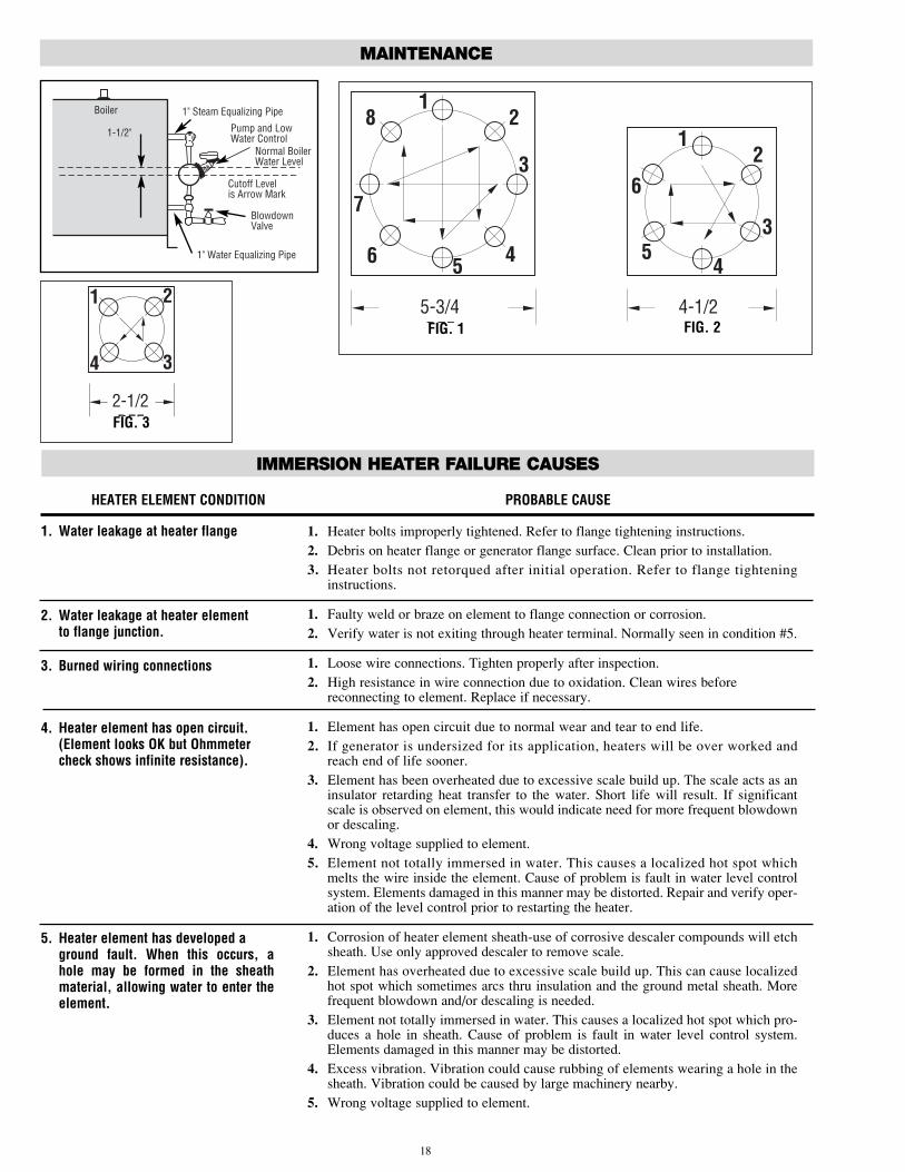
Boiler 1" Steam Equalizing Pipe
Pump and LowWater Control
Normal BoilerWater Level
Cutoff Levelis Arrow Mark
BlowdownValve
1" Water Equalizing Pipe
1-1/2"
18
128
7
3
46 5
1
6
54
3
2
5-3/4 REF.
4-1/2 REF.FIG. 1 FIG. 2
MAINTENANCE
1 2
34
2-1/2 REF.
HEATER ELEMENT CONDITION PROBABLE CAUSE
1. Water leakage at heater flange
2. Water leakage at heater elementto flange junction.
3. Burned wiring connections
4. Heater element has open circuit.(Element looks OK but Ohmmetercheck shows infinite resistance).
5. Heater element has developed aground fault. When this occurs, ahole may be formed in the sheathmaterial, allowing water to enter theelement.
1. Heater bolts improperly tightened. Refer to flange tightening instructions.2. Debris on heater flange or generator flange surface. Clean prior to installation.3. Heater bolts not retorqued after initial operation. Refer to flange tightening
instructions.
1. Faulty weld or braze on element to flange connection or corrosion.2. Verify water is not exiting through heater terminal. Normally seen in condition #5.
1. Loose wire connections. Tighten properly after inspection.2. High resistance in wire connection due to oxidation. Clean wires before
reconnecting to element. Replace if necessary.
1. Element has open circuit due to normal wear and tear to end life.2. If generator is undersized for its application, heaters will be over worked and
reach end of life sooner.3. Element has been overheated due to excessive scale build up. The scale acts as an
insulator retarding heat transfer to the water. Short life will result. If significantscale is observed on element, this would indicate need for more frequent blowdownor descaling.
4. Wrong voltage supplied to element.5. Element not totally immersed in water. This causes a localized hot spot which
melts the wire inside the element. Cause of problem is fault in water level controlsystem. Elements damaged in this manner may be distorted. Repair and verify oper-ation of the level control prior to restarting the heater.
1. Corrosion of heater element sheath-use of corrosive descaler compounds will etchsheath. Use only approved descaler to remove scale.
2. Element has overheated due to excessive scale build up. This can cause localizedhot spot which sometimes arcs thru insulation and the ground metal sheath. Morefrequent blowdown and/or descaling is needed.
3. Element not totally immersed in water. This causes a localized hot spot which pro-duces a hole in sheath. Cause of problem is fault in water level control system.Elements damaged in this manner may be distorted.
4. Excess vibration. Vibration could cause rubbing of elements wearing a hole in thesheath. Vibration could be caused by large machinery nearby.
5. Wrong voltage supplied to element.
IMMERSION HEATER FAILURE CAUSES
FIG. 3

19
RENEWAL PARTS IDENTIFICATION
Part Description Part Number
Check Valve 1/2” CES-6 through CES-18 . . . . . . . . . . . . . . . . . . 344-118536-053Check Valve 3/4” CES-24 through CES-180 . . . . . . . . . . . . . . . . 344-118536-054Gauge Glass Assembly Valves (O-ring gaskets included) . . . . . . . 344-120970-002Protector Rods (2 required) CES-6 through CES-18 . . . . . . . . . 242-121047-008Protector Rods (2 required) CES-24 through CES-72 . . . . . . . . 242-121047-001Protector Rods (2 required) CES-100 through CES-180 . . . . . . . . 242-121047-009O-Ring Gaskets (2 Required) . . . . . . . . . . . . . . . . . . . . . . . . . . . 132-073284-001Pyrex Glass 2 “O” Ring Gaskets 7 3/4”
CES-6 through CES-18 . . . . . . . . . . . . . . . . . . . . . . . . . . . . . . 374-121046-011Pyrex Glass 2 “O” Ring Gaskets 9 3/4”
CES-24 through CES-72 . . . . . . . . . . . . . . . . . . . . . . . . . . . . . 374-121046-012Pyrex Glass 2 “O” Ring Gaskets 11 3/4”
CES-120 through CES-100 . . . . . . . . . . . . . . . . . . . . . . . . . . . 374-121046-01415 psig 1/2” CES-6 through CES-36 . . . . . . . . . . . . . . . . . . . . . 344-300032-00115 psig 3/4” CES-48 through CES-72 . . . . . . . . . . . . . . . . . . . . 344-300032-01715 psig 1 1/2” CES-100 through CES-180 . . . . . . . . . . . . . . . . . 344-300032-04030 psig 1/2” CES-6 through CES-60 . . . . . . . . . . . . . . . . . . . . . 344-300032-00230 psig 3/4” CES-72 . . . . . . . . . . . . . . . . . . . . . . . . . . . . . . . . . 344-300032-01830 psig 1” CES-100 through CES-180 . . . . . . . . . . . . . . . . . . . . 344-300032-03550 psig 1/2” CES-6 through CES-72 . . . . . . . . . . . . . . . . . . . . . 344-300032-00350 psig 1” CES-100 through CES-180 . . . . . . . . . . . . . . . . . . . . 344-300032-036
100 psig 1/2” CES-6 through CES-72 . . . . . . . . . . . . . . . . . . . . 344-300032-004100 psig 3/4” CES-160 through CES-180 . . . . . . . . . . . . . . . . . 344-300032-020Operating Pressure Controls 10-100 psi . . . . . . . . . . . . . . . . . . 292-300031-001Hi-Limit Control Manual Reset 90 psi . . . . . . . . . . . . . . . . . . . . 292-300031-002
5-Step Solid State Sequencer . . . . . . . . . . . . . . . . . . . . . . . . . . 323-300107-01510-Step Solid State Sequencer . . . . . . . . . . . . . . . . . . . . . . . . . 323-300107-015Siphon Tube for Pressure Controls . . . . . . . . . . . . . . . . . . . . . . 215-300026-002MM-150 Control Complete (Auto Reset) . . . . . . . . . . . . . . . . . . 292-300065-001MM-150M Control Complete (Manual Reset) . . . . . . . . . . . . . . 292-300065-002Float and Rod for MM-150 & MM-150M . . . . . . . . . . . . . . . . . . 292-300065-102Complete Head Mechanism (Auto Reset) . . . . . . . . . . . . . . . . . 292-300065-100Complete Head Mechanism (Manual Reset) . . . . . . . . . . . . . . . 292-300065-101Head Gasket . . . . . . . . . . . . . . . . . . . . . . . . . . . . . . . . . . . . . . . . 292-300065-1033 Wire Cut-off & Alarm Switch (Auto Reset) . . . . . . . . . . . . . . . 292-300065-1043 Wire Cut-off & Alarm Switch (Manual Reset) . . . . . . . . . . . . . 292-300065-1052 Wire Pump Switch . . . . . . . . . . . . . . . . . . . . . . . . . . . . . . . . . 292-300065-106Bellows Base Clamp & Bellows Assembly (Auto Reset) . . . . . . . . 292-300065-108Bellows Base Clamp & Bellows Assembly (Manual Reset) . . . . . . 292-300065-109
Bellows Base Gasket . . . . . . . . . . . . . . . . . . . . . . . . . . . . . . . . . 292-300065-110Bellows Base Clamp Assembly (Auto Reset) . . . . . . . . . . . . . . . 292-300065-111Bellows Base Clamp Assembly (Manual Reset) . . . . . . . . . . . . . 292-300065-112
Bellows Base Assembly with Gasket . . . . . . . . . . . . . . . . . . . . . 292-300065-113
1KVA 208V Primary . . . . . . . . . . . . . . . . . . . . . . . . . . . . . . . . . . 315-300088-0201KVA 240/480V Primary . . . . . . . . . . . . . . . . . . . . . . . . . . . . . . 315-300088-0211 1/2 KVA 208V Primary . . . . . . . . . . . . . . . . . . . . . . . . . . . . . . 315-300088-0251 1/2 KVA 240/480V Primary . . . . . . . . . . . . . . . . . . . . . . . . . . . 315-300088-026Solenoid Valve . . . . . . . . . . . . . . . . . . . . . . . . . . . . . . . . . . . . . . 344-121780-002Strainer . . . . . . . . . . . . . . . . . . . . . . . . . . . . . . . . . . . . . . . . . . . 351-118664-001THREE PHASE12kW 208V . . . . . . . . . . . . . . . . . . . . . . . . . . . . . . . . . . . . . . . . 155-554735-04412kW 240V . . . . . . . . . . . . . . . . . . . . . . . . . . . . . . . . . . . . . . . . 155-554735-03212kW 480V . . . . . . . . . . . . . . . . . . . . . . . . . . . . . . . . . . . . . . . . 155-554735-01517kW 208V . . . . . . . . . . . . . . . . . . . . . . . . . . . . . . . . . . . . . . . . 155-554735-04817kW 240V . . . . . . . . . . . . . . . . . . . . . . . . . . . . . . . . . . . . . . . . 155-554735-02817kW 480V . . . . . . . . . . . . . . . . . . . . . . . . . . . . . . . . . . . . . . . . 155-554735-016Gasket . . . . . . . . . . . . . . . . . . . . . . . . . . . . . . . . . . . . . . . . . . . . 132-146012-011
GAUGE GLASS ASSEMBLIES, CHECK VALVES & SIGHT GLASSES
PRESSURE CONTROLS & SEQUENCES
LOW WATER CUTOFF & PUMP CONTROLS
CONTROL VOLTAGE TRANSFORMERS (120V SECONDARY)
LOW PRESSURE WATER FEED (ES-99117)
CORROSION RESISTANT ELEMENTS & GASKETS
Part Description Part Number
Motor and Pump used in ES-38002 . . . . . . . . . . . . . . . . . . . . . . 226-300177-001Motor and Pump used in ES-38020 . . . . . . . . . . . . . . . . . . . . . . 226-300177-004Pump only used in ES-38002 . . . . . . . . . . . . . . . . . . . . . . . . . . 226-300173-001Pump only used in ES-38020 . . . . . . . . . . . . . . . . . . . . . . . . . . 226-300173-004Motor only used in ES-38002 115V 60Hz . . . . . . . . . . . . . . . . . 193-300175-001Motor only used in ES-38002 230V 50Hz . . . . . . . . . . . . . . . . . 193-300175-002Motor only used in ES-38020 115V 60Hz . . . . . . . . . . . . . . . . . 193-300175-004Strainer used in ES-38020 . . . . . . . . . . . . . . . . . . . . . . . . . . . . . 351-118664-001V-Band Mount used in ES-38002 & ES-38020 . . . . . . . . . . . . . 355-300174-001Solenoid Valve used in ES-38002 & ES-38020 . . . . . . . . . . . . . 344-121780-002Hose Assembly 18” Long used in ES-38002 & ES-38020 . . . . . . . 349-300181-002Pump Base . . . . . . . . . . . . . . . . . . . . . . . . . . . . . . . . . . . . . . . . . 015-300125-001Adapter for Hose used in ES-38002 . . . . . . . . . . . . . . . . . . . . . . 001-300180-001
Adapter for Hose used in ES-38020 . . . . . . . . . . . . . . . . . . . . . . 001-300180-002Pump and Motor Assembly used in ES-38083V 26 Gal. . . . . . . 226-300172-003Pump and Motor Assembly used in ES-38084V 33 Gal. . . . . . . 226-300172-006Condensate Tank only used in ES-38083V 26 Gal. . . . . . . . . . . 226-300218-001Condensate Tank only used in ES-38084V 33 Gal. . . . . . . . . . . 226-300218-002Parts Common to both 26 & 33 Gal. SystemsImpeller Raceway for Pump . . . . . . . . . . . . . . . . . . . . . . . . . . . . 226-118671-001Seal for Pump . . . . . . . . . . . . . . . . . . . . . . . . . . . . . . . . . . . . . . 251-118657-002“O” Ring . . . . . . . . . . . . . . . . . . . . . . . . . . . . . . . . . . . . . . . . . . . 251-118657-003Float Valve Assembly (Float Valve & Stem) . . . . . . . . . . . . . . . . 344-300223-006Disc Cover Assembly (Less Float Valve) . . . . . . . . . . . . . . . . . . 101-300220-001Gasket for Disc Cover . . . . . . . . . . . . . . . . . . . . . . . . . . . . . . . . 132-300224-001Frame Assembly (Less Tank) . . . . . . . . . . . . . . . . . . . . . . . . . . . 126-300221-001Strainer 1” NPT . . . . . . . . . . . . . . . . . . . . . . . . . . . . . . . . . . . . . 351-118664-019Gauge Glass Valve Set . . . . . . . . . . . . . . . . . . . . . . . . . . . . . . . . 344-120970-002Gauge Glass . . . . . . . . . . . . . . . . . . . . . . . . . . . . . . . . . . . . . . . . 374-121046-011Gauge Glass Protector Rods (2 Required) . . . . . . . . . . . . . . . . . 242-121047-008Manual Valve . . . . . . . . . . . . . . . . . . . . . . . . . . . . . . . . . . . . . . . 344-121194-002Sight Glass Assembly . . . . . . . . . . . . . . . . . . . . . . . . . . . . . . . . 130-073287-004Drain Valve . . . . . . . . . . . . . . . . . . . . . . . . . . . . . . . . . . . . . . . . . 344-121194-006
Probe Spark Plug . . . . . . . . . . . . . . . . . . . . . . . . . . . . . . . . . . . . 346-300035-001Aux Low Water Cut-off Board with Relay . . . . . . . . . . . . . . . . . . 323-300033-016Aux Low Water Cut-off Board Without Relay . . . . . . . . . . . . . . . 323-300033-017Relay for Aux Low Cut-off Board . . . . . . . . . . . . . . . . . . . . . . . . 072-300047-003Probe 7 15/16” CES 6-20 . . . . . . . . . . . . . . . . . . . . . . . . . . . . . . 242-300036-019Probe 9 1/2” CES 24-72 . . . . . . . . . . . . . . . . . . . . . . . . . . . . . . . 242-300036-002
Probe 10 15/16” CES-100 through CES-180 . . . . . . . . . . . . . . . 242-300036-017ON-OFF Switch with Pilot Light . . . . . . . . . . . . . . . . . . . . . . . . . 292-053223-002Control Circuit Fuse . . . . . . . . . . . . . . . . . . . . . . . . . . . . . . . . . . 128-072576-027Control Circuit Terminal Block 4 Pole 250V 20AMP . . . . . . . . . 303-075443-003Control Circuit Fuse Block . . . . . . . . . . . . . . . . . . . . . . . . . . . . . 129-300029-001Blank Flange . . . . . . . . . . . . . . . . . . . . . . . . . . . . . . . . . . . . . . . . 121-300199-001Element Gasket . . . . . . . . . . . . . . . . . . . . . . . . . . . . . . . . . . . . . 132-146012-011
Stainless Steel Bolts (6 required) for Element . . . . . . . . . . . . . . 345-072565-428Vacuum Breaker Assembly . . . . . . . . . . . . . . . . . . . . . . . . . . . . 344-300149-001Motorized Valve 1/2” CES-6 through CES-18 . . . . . . . . . . . . . . 344-300089-002Motorized Valve 1” CES-24 through CES-180 . . . . . . . . . . . . . . 344-300089-005Timer . . . . . . . . . . . . . . . . . . . . . . . . . . . . . . . . . . . . . . . . . . . . . 292-300101-002Relay SPST No. 2 . . . . . . . . . . . . . . . . . . . . . . . . . . . . . . . . . . . . 072-300072-002Relay Interval Delay .6-60 Sec. 3 . . . . . . . . . . . . . . . . . . . . . . . . 072-300148-003Switch Momentary Contact DPDT 4 . . . . . . . . . . . . . . . . . . . . . . 292-300146-001Switch Rocker SPDT 5 . . . . . . . . . . . . . . . . . . . . . . . . . . . . . . . . 272-300147-001Pilot Light Red 6 . . . . . . . . . . . . . . . . . . . . . . . . . . . . . . . . . . . . 213-300145-001Terminal Block 4 Pole . . . . . . . . . . . . . . . . . . . . . . . . . . . . . . . . 303-075444-003Terminal Block 5 Pole . . . . . . . . . . . . . . . . . . . . . . . . . . . . . . . . 303-075444-004Fuse Block 30A . . . . . . . . . . . . . . . . . . . . . . . . . . . . . . . . . . . . . 129-024494-001Fuse 15A . . . . . . . . . . . . . . . . . . . . . . . . . . . . . . . . . . . . . . . . . . 128-121133-072Motorized Ball Valve (Size 1/2) . . . . . . . . . . . . . . . . . . . . . . . . . 344-300089-001Motorized Ball Valve (Size 1/2) . . . . . . . . . . . . . . . . . . . . . . . . . 344-300089-002Motorized Ball Valve (Size 1/2) . . . . . . . . . . . . . . . . . . . . . . . . . 344-300089-003Motorized Ball Valve (Size 1) . . . . . . . . . . . . . . . . . . . . . . . . . . . 344-300089-004Motorized Ball Valve (Size 1) . . . . . . . . . . . . . . . . . . . . . . . . . . . 344-300089-005
Motorized Ball Valve (Size 1) . . . . . . . . . . . . . . . . . . . . . . . . . . . 344-300089-006Operating Pressure Control 2-15 psi . . . . . . . . . . . . . . . . . . . . . 292-300038-001Hi-Limit Control (Manual Reset) 15 psi . . . . . . . . . . . . . . . . . . . 292-300038-005Proportional Pressure Control 2-15 psi . . . . . . . . . . . . . . . . . . . 292-300039-001Operating Pressure Control 5-50 psi . . . . . . . . . . . . . . . . . . . . . 292-300038-002Hi-Limit Control (Manual Reset) 50 psi . . . . . . . . . . . . . . . . . . . 292-300038-006Proportional Pressure Control 2-50 psi . . . . . . . . . . . . . . . . . . . 292-300039-002Operating Pressure Control 10-150 psi . . . . . . . . . . . . . . . . . . . 292-300038-003Hi-Limit Control (Manual Reset) 90 psi . . . . . . . . . . . . . . . . . . . 292-300038-007Proportional Pressure Control 5-150 psi . . . . . . . . . . . . . . . . . . 292-300039-003
CONDENSATE RETURN SYSTEMS
AUX LOW WATER CUT-OFF (OPTIONAL EQUIPMENT)
MISCELLANEOUS PARTS
AUTO BLOWDOWN PARTS
HONEYWELL PRESSURE CONTROLS
SAFETY VALVE
COLD WATER INJECTION PUMPS (0-100 PSIG)

2150 N. RULON WHITE BLVD., OGDEN, UT 84404Phone: 1-800-368-2493 www.chromalox.com
RENEWAL PARTS IDENTIFICATION
Part Description Part Number
1/4” Ball Valve (Pressure Gauge) . . . . . . . . . . . . . . . . . . . . . . . . 344-300323-002Blowdown Valve 1/2” CES-6 through CES-18 . . . . . . . . . . . . . . 344-121194-006Blowdown Valve 1” CES-24 through CES-180 . . . . . . . . . . . . . . 344-121194-002Pressure Gauge 2” 0-160 psi CES-6 through
CES-72 (50 and 100 psi trim) . . . . . . . . . . . . . . . . . . . . . . . . 130-118661-001Pressure Gauge 3 1/2” 0-160 psi CES-100 through
CES-180 (50 and 100 psi trim) . . . . . . . . . . . . . . . . . . . . . . . 130-118661-009Pressure Gauge 2 1/2” 0-60 psi CES-6 through
CES-72 (30 psi trim) . . . . . . . . . . . . . . . . . . . . . . . . . . . . . . . 130-118661-003Pressure Gauge 3 1/2” 0-60 psi CES-100 through
CES-180 (30 psi trim) . . . . . . . . . . . . . . . . . . . . . . . . . . . . . . 130-118661-007Pressure Gauge 2 1/2” 0-30 psi CES-6 through
CES-72 (15 psi trim) . . . . . . . . . . . . . . . . . . . . . . . . . . . . . . . 130-118661-013Pressure Gauge 3 1/2” 0-30 psi CES-100 through
CES-180 (15 psi trim) . . . . . . . . . . . . . . . . . . . . . . . . . . . . . . 130-118661-006
Fusable Contactors30 amps with 35-60 amp 600V block . . . . . . . . . . . . . . . . . . . . 072-122686-00340 amps with 35-60 amp 600V block . . . . . . . . . . . . . . . . . . . . 072-122686-00650 amps with 35-60 amp 600V block . . . . . . . . . . . . . . . . . . . . 072-122686-009Non-fusable Contactors60 amp without fuse block . . . . . . . . . . . . . . . . . . . . . . . . . . . . . 072-047913-01650 amp without fuse block . . . . . . . . . . . . . . . . . . . . . . . . . . . . . 072-047913-01940 amp without fuse block . . . . . . . . . . . . . . . . . . . . . . . . . . . . . 072-047913-012
30 amp without fuse block . . . . . . . . . . . . . . . . . . . . . . . . . . . . . 072-047913-020
35 amp 600V . . . . . . . . . . . . . . . . . . . . . . . . . . . . . . . . . . . . . . . 128-121138-03340 amp 600V . . . . . . . . . . . . . . . . . . . . . . . . . . . . . . . . . . . . . . . 128-121133-06445 amp 600V . . . . . . . . . . . . . . . . . . . . . . . . . . . . . . . . . . . . . . . 128-121133-06550 amp 600V . . . . . . . . . . . . . . . . . . . . . . . . . . . . . . . . . . . . . . . 128-121133-06660 amp 600V . . . . . . . . . . . . . . . . . . . . . . . . . . . . . . . . . . . . . . . 128-121133-067Fuse Block 35-60 amp 60 amp 600V . . . . . . . . . . . . . . . . . . . . . 129-047445-002Power Terminal Blocks3 pole 115 amp 1 line circuit 1 load circuits . . . . . . . . . . . . . . . 303-071809-0323 pole 175 amp 1 line circuit 4 load circuits . . . . . . . . . . . . . . . 303-071809-0123 pole 335 amp 1 line circuit 4 load circuits . . . . . . . . . . . . . . . 303-071809-0143 pole 335 amp 1 line circuit 8 load circuits . . . . . . . . . . . . . . . 303-071809-016
SINGLE PHASE12kW 208V . . . . . . . . . . . . . . . . . . . . . . . . . . . . . . . . . . . . . . . . 155-554735-00412kW 480V . . . . . . . . . . . . . . . . . . . . . . . . . . . . . . . . . . . . . . . . 155-554735-00917kW 208V . . . . . . . . . . . . . . . . . . . . . . . . . . . . . . . . . . . . . . . . 155-554735-00617kW 480V . . . . . . . . . . . . . . . . . . . . . . . . . . . . . . . . . . . . . . . . 155-554735-011THREE PHASE12kW 208V . . . . . . . . . . . . . . . . . . . . . . . . . . . . . . . . . . . . . . . . 155-554735-00312kW 240V . . . . . . . . . . . . . . . . . . . . . . . . . . . . . . . . . . . . . . . . 155-554735-00112kW 346V . . . . . . . . . . . . . . . . . . . . . . . . . . . . . . . . . . . . . . . . 155-554735-01212kW 380V . . . . . . . . . . . . . . . . . . . . . . . . . . . . . . . . . . . . . . . . 155-554735-01712kW 480V . . . . . . . . . . . . . . . . . . . . . . . . . . . . . . . . . . . . . . . . 155-554735-00817kW 208V . . . . . . . . . . . . . . . . . . . . . . . . . . . . . . . . . . . . . . . . 155-554735-00517kW 240V . . . . . . . . . . . . . . . . . . . . . . . . . . . . . . . . . . . . . . . . 155-554735-00217kW 346V . . . . . . . . . . . . . . . . . . . . . . . . . . . . . . . . . . . . . . . . 155-554735-01317kW 380V . . . . . . . . . . . . . . . . . . . . . . . . . . . . . . . . . . . . . . . . 155-554735-01817kW 480V . . . . . . . . . . . . . . . . . . . . . . . . . . . . . . . . . . . . . . . . 155-554735-01022.5kW 240V . . . . . . . . . . . . . . . . . . . . . . . . . . . . . . . . . . . . . . . 155-554735-02122.5kW 480V . . . . . . . . . . . . . . . . . . . . . . . . . . . . . . . . . . . . . . . 155-554735-02222.5kW 550V . . . . . . . . . . . . . . . . . . . . . . . . . . . . . . . . . . . . . . . 155-554735-019
VALVES & GAUGES
CONTACTORS
POWER FUSES AND TERMINAL BLOCKS
HEATING ELEMENTS — SPECIFY VOLTAGE
Gate Valves
AutomaticBlowdown
Valve
Insulation
HeatingElements
Sight Glass
AutomaticBlowdown
Control
Steam Outlet
Safety Valve Manual Reset High Limit Control
Steam Pressure Gauge
OperatingPressureControl
Vacuum Breaker
McDowell & MillerLow Water Cutoffand Pump Control
Fuses, TerminalBlocks andContactors
Check ValveWater Feed
Strainer
Limited Warranty:Please refer to the Chromalox limited warranty applicable to this product at
http://www.chromalox.com/customer-service/policies/termsofsale.aspx.