340D & 350D SERIES FRAMELESS BYPASS 800-643-1514 BATH ...
8
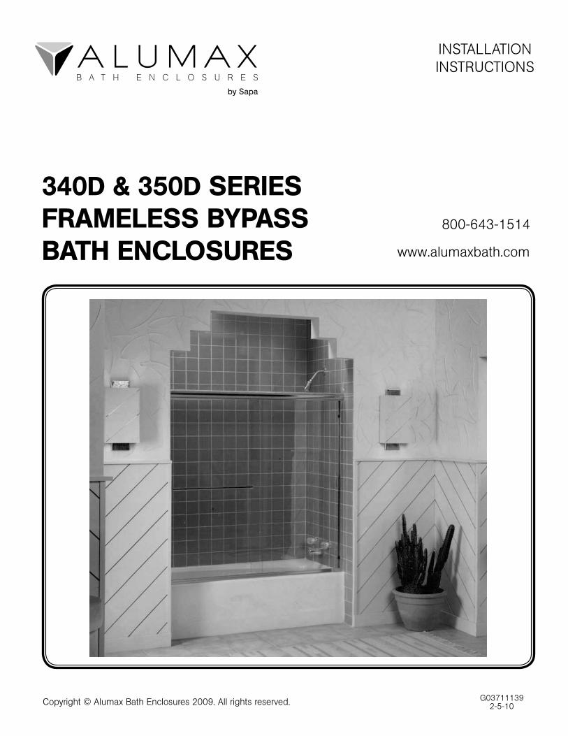
G03711139 2-5-10 INSTALLATION INSTRUCTIONS 340D & 350D SERIES FRAMELESS BYPASS BATH ENCLOSURES 800-643-1514 www.alumaxbath.com Copyright © Alumax Bath Enclosures 2009. All rights reserved.
Transcript of 340D & 350D SERIES FRAMELESS BYPASS 800-643-1514 BATH ...
G037111392-5-10
INSTALLATIONINSTRUCTIONS
340D & 350D SERIESFRAMELESS BYPASSBATH ENCLOSURES
800-643-1514
www.alumaxbath.com
Copyright © Alumax Bath Enclosures 2009. All rights reserved.
G037111392-5-10
Page 2
LIMITED WARRANTY AND REMEDY
ALUMAX BATH ENCLOSURES warrants to its dealers, customers, and all subsequent purchasers and users, that the products supplied by it shall be free from material defects in material and workmanship for a period of one (1) year after shipment, provided they are installed and maintained according to ALUMAX BATH ENCLOSURE'S recommended practices and installation instructions. This warranty shall apply only to defects appearing within one (1) year from the date of shipment, and provided that ALUMAX BATH ENCLOSURES is promptly notified in writing of such defects. The sole and exclusive remedy with respect to the above warranty or with respect to any other claim relating to defects or any other condition or use of the products supplied by ALUMAX BATH ENCLOSURES, however caused, and whether such claim is based upon warranty contract, negligence, strict liability, or any other theory, is limited to repair or supply of such products, or repayment by ALUMAX BATH ENCLOSURES of the purchase price paid for it, at ALUMAX BATH ENCLOSURE'S option.
ALUMAX BATH ENCLOSURES does not make any other representations or warranties, express or implied, including, but not limited to, any implied warranty of merchantability and any implied warranty of fitness for a particular purpose. In no event shall ALUMAX BATH ENCLOSURES be liable for special, direct, indirect, or consequential damages, including, but not limited to, loss or use of profits.
Dealers agree to pass on to its customers and users in writing ALUMAX BATH ENCLOSURE'S Warranty and Remedy as set forth above.
Laws and building and safety codes governing the design and use of bath enclosures vary widely. ALUMAX BATH ENCLOSURES does not control the selection of product configurations, operating hardware or glazing materials, and assumes no responsibility therefor.
INSTALLATION NOTES
Unpack your unit carefully and inspect for freight damage. Lay out and identify all parts using the in-struction sheets as a reference. Before discarding the carton, check for small hardware bags that tend to fall to the bottom of the box. If any parts are damaged or missing, refer to the descriptions noted in the instructions when contacting your dealer for replacements.
Handle glazed panels carefully. Tempered glass is difficult to break, but the sharp corners of the panels can damage tile and floor coverings.
Please wear safety glasses whenever drilling or cutting.
To install your ALUMAX Bath Enclosure you will need the following: tape measure, level, hacksaw, drill, 1/8", 7/64" and 7/32" drill bits, #2 Phillips screwdriver, flat screwdriver, sharp knife, and caulking (clear silicone recommended). Optional tools include a center punch, files, a miter box for cutting parts to length and masking tape for holding parts in place temporarily.
NOTE: Before beginning installation, check the tub rim for level and both walls for plumb. If either are off more than 1/4" to 3/8", you may want to contact your dealer for tapered fillers which can be used to level the tub track or plumb the jambs.
Page 3 G037111392-5-10
A.
1 Tu
b Tr
ack
B.
2 W
all J
ambs
C.
6 Pl
astic
Wal
l Anc
hors
D.
6 #
8 X
1 1
/2"
Trus
s H
ead
Scr
ews
E.
4 N
ylon
Spa
cers
F.
1 H
eade
rG
. 2 G
lass
Lite
sH
. 4
Han
ger B
rack
ets
(Pre
-Ass
embl
ed)
I. 4
End
Cap
sJ.
4
Plas
tic W
ashe
rs (
Larg
e H
ole)
K.
4 Pl
astic
Was
hers
(S
mal
l Hol
e)
L. 4
Gla
ss In
serts
M. 4
Met
al W
ashe
rsN
. 2
Tow
el B
ars
O. 1
Nyl
on B
otto
m G
uide
P.
2 #
6 X
3/8
" Pa
n H
ead
Scr
ews
Q. 4
Sta
inle
ss B
umpe
r In
serts
R.
4 Vin
yl J
amb
Bum
pers
S.
1 Vin
yl S
ilenc
erT.
1
Wre
nch
U.
1 B
otto
m B
umpe
r (O
ptio
nal)
340D
-350
D P
AR
TS L
IST
G037111392-5-10
Page 4
1
Use a level to plumb both wall jambs [B], then mark the pre-drilled hole locations on the wall. Lightly mark along both sides of the tub track [A] with a pencil, then remove all parts.
For tile or marble walls, drill six 7/32" diameter holes and insert the plastic wall anchors [C]. A center punch helps locate the holes accurately.
Attachments to fiberglass or acrylic units can be made in two ways. If a reinforcement is built into the wall of the unit, drill six 1/8" diameter holes and install the screws directly into the reinforcement. If the walls are not rein-forced, drill 7/32" holes and install plastic wall anchors or molly bolts (molly bolts not supplied by ALUMAX).
CAUTION: The track should never be screwed to the tub. This will damage the tub and cause leakage.
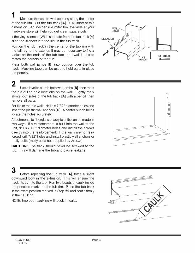
Measure the wall-to-wall opening along the center of the tub rim. Cut the tub track [A] 1/16" short of this dimension. An inexpensive miter box available at your hardware store will help you get clean square cuts.
If the vinyl silencer (W) is separate from the tub track (A) slide the silencer into the slot in the tub track.
Position the tub track in the center of the tub rim with the tall leg to the exterior. It may be necessary to file a radius on the ends of the tub track and wall jambs to match the corners of the tub.
Press both wall jambs [B] into position over the tub track. Masking tape can be used to hold parts in place temporarily.
2
3 Before replacing the tub track [A], force a slight downward bow in the extrusion. This will ensure the track fits tight to the tub. Run two beads of caulk inside the penciled marks on the tub rim. Place the tub track in the exact position marked in Step #2 and seat it firmly in the caulking.
NOTE: Improper caulking will result in leaks. TUBTRACK
Page 5 G037111392-5-10
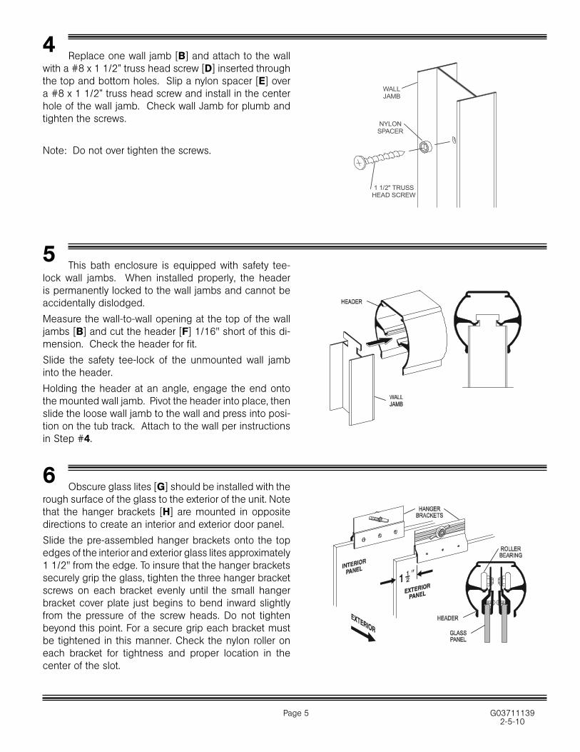
4 Replace one wall jamb [B] and attach to the wall with a #8 x 1 1/2” truss head screw [D] inserted through the top and bottom holes. Slip a nylon spacer [E] over a #8 x 1 1/2” truss head screw and install in the center hole of the wall jamb. Check wall Jamb for plumb and tighten the screws.
Note: Do not over tighten the screws.
6 Obscure glass lites [G] should be installed with the rough surface of the glass to the exterior of the unit. Note that the hanger brackets [H] are mounted in opposite directions to create an interior and exterior door panel.
Slide the pre-assembled hanger brackets onto the top edges of the interior and exterior glass lites approximately 1 1/2" from the edge. To insure that the hanger brackets securely grip the glass, tighten the three hanger bracket screws on each bracket evenly until the small hanger bracket cover plate just begins to bend inward slightly from the pressure of the screw heads. Do not tighten beyond this point. For a secure grip each bracket must be tightened in this manner. Check the nylon roller on each bracket for tightness and proper location in the center of the slot.
This bath enclosure is equipped with safety tee-lock wall jambs. When installed properly, the header is permanently locked to the wall jambs and cannot be accidentally dislodged.
Measure the wall-to-wall opening at the top of the wall jambs [B] and cut the header [F] 1/16" short of this di-mension. Check the header for fit.
Slide the safety tee-lock of the unmounted wall jamb into the header.
Holding the header at an angle, engage the end onto the mounted wall jamb. Pivot the header into place, then slide the loose wall jamb to the wall and press into posi-tion on the tub track. Attach to the wall per instructions in Step #4.
5
1 1/2" TRUSSHEAD SCREW
NYLONSPACER
WALLJAMB
G037111392-5-10
Page 6
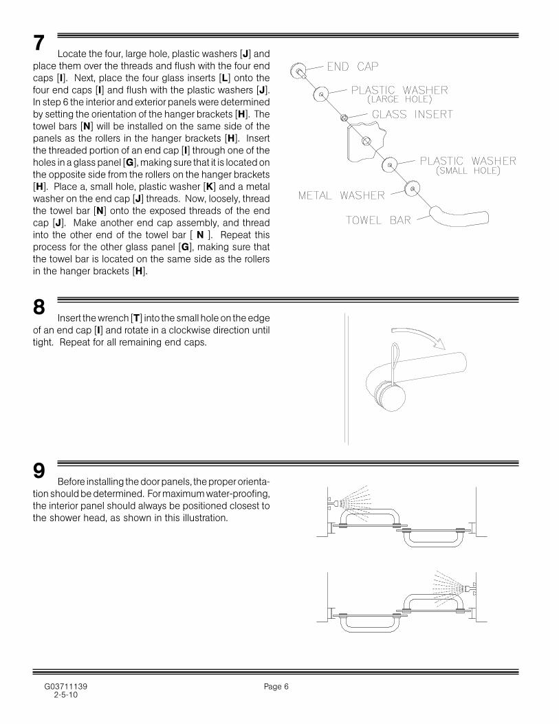
7 Locate the four, large hole, plastic washers [J] and place them over the threads and flush with the four end caps [I]. Next, place the four glass inserts [L] onto the four end caps [I] and flush with the plastic washers [J]. In step 6 the interior and exterior panels were determined by setting the orientation of the hanger brackets [H]. The towel bars [N] will be installed on the same side of the panels as the rollers in the hanger brackets [H]. Insert the threaded portion of an end cap [I] through one of the holes in a glass panel [G], making sure that it is located on the opposite side from the rollers on the hanger brackets [H]. Place a, small hole, plastic washer [K] and a metal washer on the end cap [J] threads. Now, loosely, thread the towel bar [N] onto the exposed threads of the end cap [J]. Make another end cap assembly, and thread into the other end of the towel bar [ N ]. Repeat this process for the other glass panel [G], making sure that the towel bar is located on the same side as the rollers in the hanger brackets [H].
Before installing the door panels, the proper orienta-tion should be determined. For maximum water-proofing, the interior panel should always be positioned closest to the shower head, as shown in this illustration.
9
Insert the wrench [T] into the small hole on the edge of an end cap [I] and rotate in a clockwise direction until tight. Repeat for all remaining end caps.
8
Page 7 G037111392-5-10
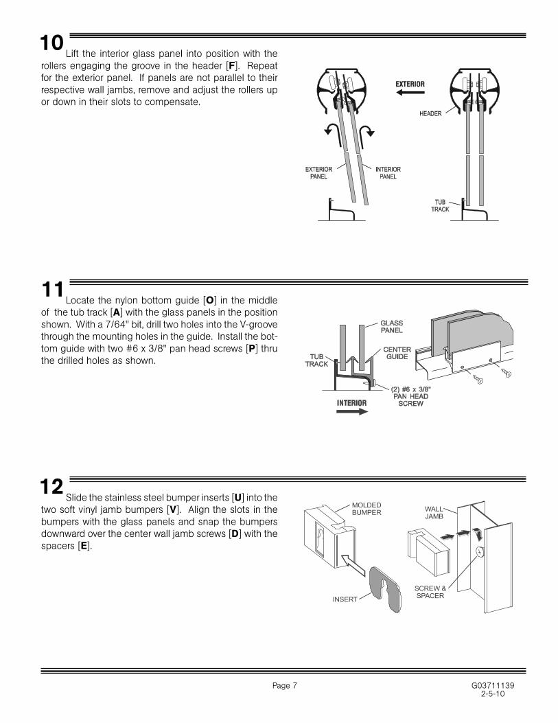
Lift the interior glass panel into position with the rollers engaging the groove in the header [F]. Repeat for the exterior panel. If panels are not parallel to their respective wall jambs, remove and adjust the rollers up or down in their slots to compensate.
10
Slide the stainless steel bumper inserts [U] into the two soft vinyl jamb bumpers [V]. Align the slots in the bumpers with the glass panels and snap the bumpers downward over the center wall jamb screws [D] with the spacers [E].
12
Locate the nylon bottom guide [O] in the middle of the tub track [A] with the glass panels in the position shown. With a 7/64" bit, drill two holes into the V-groove through the mounting holes in the guide. Install the bot-tom guide with two #6 x 3/8" pan head screws [P] thru the drilled holes as shown.
11
INSERTSCREW &SPACER
WALLJAMB
MOLDEDBUMPER
G037111392-5-10
Page 8
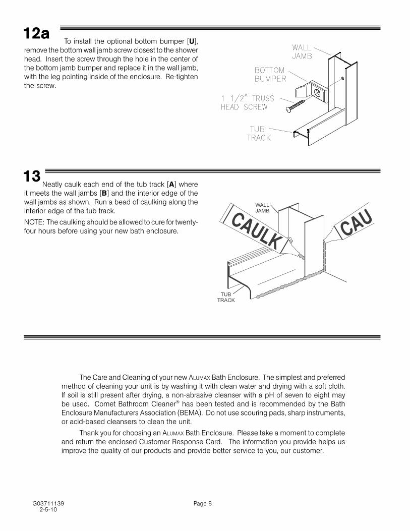
Neatly caulk each end of the tub track [A] where it meets the wall jambs [B] and the interior edge of the wall jambs as shown. Run a bead of caulking along the interior edge of the tub track.
NOTE: The caulking should be allowed to cure for twenty-four hours before using your new bath enclosure.
13
TUBTRACK
WALLJAMB
The Care and Cleaning of your new ALUMAX Bath Enclosure. The simplest and preferred method of cleaning your unit is by washing it with clean water and drying with a soft cloth. If soil is still present after drying, a non-abrasive cleanser with a pH of seven to eight may be used. Comet Bathroom Cleaner® has been tested and is recommended by the Bath Enclosure Manufacturers Association (BEMA). Do not use scouring pads, sharp instruments, or acid-based cleansers to clean the unit.
Thank you for choosing an ALUMAX Bath Enclosure. Please take a moment to complete and return the enclosed Customer Response Card. The information you provide helps us improve the quality of our products and provide better service to you, our customer.
To install the optional bottom bumper [U], remove the bottom wall jamb screw closest to the shower head. Insert the screw through the hole in the center of the bottom jamb bumper and replace it in the wall jamb, with the leg pointing inside of the enclosure. Re-tighten the screw.
12a