MTS Criterion Series 40 Electromechanical Universal Test ...

I-201
5, w
ww
.find
erne
t.com
34 SERIES34 Series - Slim electromechanical PCB relays 6 A
1
A
Ultra-slim 1 Pole - 6 A relay
Printed circuit mount- direct or via PCB socket
35 mm rail mount- via screw, screwless or push-in terminal
sockets
• 1 Pole changeover contacts or 1 Pole normally open contact
• Ultra slim, 5 mm, package• Sensitive DC coil - 170 mW (Dual AC/DC coil
drive possible using 93 series sockets)• UL Listing (certain relay/socket combinations)• Cadmium Free contact materials• 8/8 mm clearance/creepage distance• 6 kV (1.2/50 μs) insulation, coil-contacts
34.51
• 5 mm wide• Low coil power• PCB or 93 series sockets
Copper side view
For UL ratings see:“General technical information” page V
For outline drawing see page 5
Contact specification
Contact configuration 2 CO (SPDT)
Rated current/ Maximum peak current A 6/10Rated voltage/ Maximum switching voltage V AC 250/400
Rated load AC1 VA 1500
Rated load AC15 (230 V AC) VA 300
Single phase motor rating (230 V AC) kW 0.185
Breaking capacity DC1: 30/110/220 V A 6/0.2/0.12
Minimum switching load mW (V/mA) 500 (12/10)
Standard contact material AgNi
Coil specification
Nominal voltage (UN) V AC (50/60 Hz) —
V DC 5 - 12 - 24 - 48 - 60
Rated power AC/DC VA (50 Hz)/W —/0.17
Operating range AC —
DC (0.7…1.5)UN
Holding voltage AC/DC —/0.4 UN
Must drop-out voltage AC/DC —/0.05 UN
Technical data
Mechanical life AC/DC cycles —/10 · 106
Electrical life at rated load AC1 cycles 60 · 103
Operate/release time ms 5/3
Insulation between coil and contacts (1.2/50 µs) kV 6 (8mm)Dielectric strength between open contacts V AC 1000
Ambient temperature range °C –40…+85
Environmental protection RT II
Approvals (according to type)
I-201
5, w
ww
.find
erne
t.com
34 SERIES 34 Series - Slim solid state PCB relays (SSR) 0.1 - 2 A
2
A
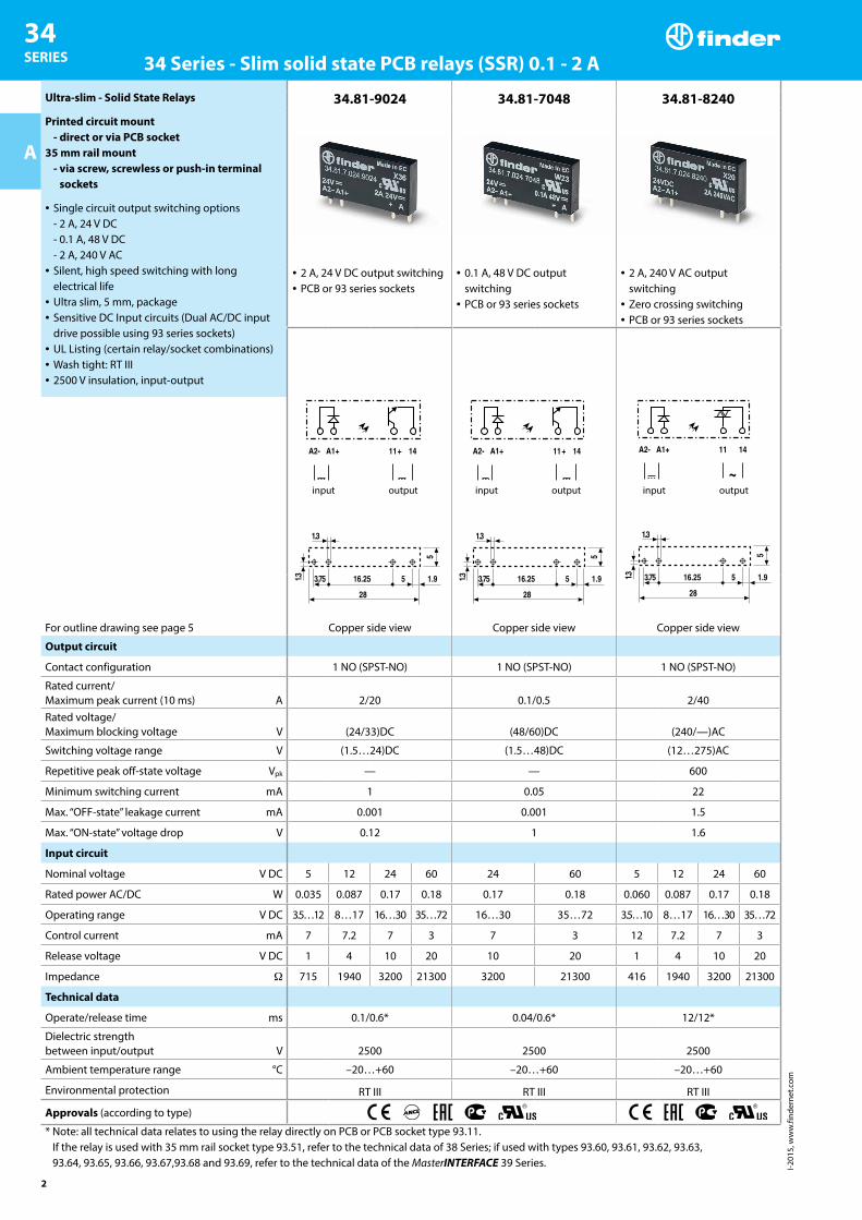
Ultra-slim - Solid State Relays
Printed circuit mount- direct or via PCB socket
35 mm rail mount- via screw, screwless or push-in terminal
sockets
• Single circuit output switching options- 2 A, 24 V DC- 0.1 A, 48 V DC- 2 A, 240 V AC
• Silent, high speed switching with long electrical life
• Ultra slim, 5 mm, package• Sensitive DC Input circuits (Dual AC/DC input
drive possible using 93 series sockets)• UL Listing (certain relay/socket combinations)• Wash tight: RT III• 2500 V insulation, input-output
34.81-9024 34.81-7048 34.81-8240
• 2 A, 24 V DC output switching• PCB or 93 series sockets
• 0.1 A, 48 V DC output switching
• PCB or 93 series sockets
• 2 A, 240 V AC output switching
• Zero crossing switching• PCB or 93 series sockets
input output
Copper side view
input output
Copper side view
input output
Copper side viewFor outline drawing see page 5
Output circuit
Contact configuration 1 NO (SPST-NO) 1 NO (SPST-NO) 1 NO (SPST-NO)
Rated current/ Maximum peak current (10 ms) A 2/20 0.1/0.5 2/40Rated voltage/ Maximum blocking voltage V (24/33)DC (48/60)DC (240/—)AC
Switching voltage range V (1.5…24)DC (1.5…48)DC (12…275)AC
Repetitive peak off-state voltage Vpk — — 600
Minimum switching current mA 1 0.05 22
Max. “OFF-state” leakage current mA 0.001 0.001 1.5
Max. “ON-state” voltage drop V 0.12 1 1.6
Input circuit
Nominal voltage V DC 5 12 24 60 24 60 5 12 24 60
Rated power AC/DC W 0.035 0.087 0.17 0.18 0.17 0.18 0.060 0.087 0.17 0.18
Operating range V DC 3.5…12 8…17 16…30 35…72 16…30 35…72 3.5…10 8…17 16…30 35…72
Control current mA 7 7.2 7 3 7 3 12 7.2 7 3
Release voltage V DC 1 4 10 20 10 20 1 4 10 20
Impedance Ω 715 1940 3200 21300 3200 21300 416 1940 3200 21300
Technical data
Operate/release time ms 0.1/0.6* 0.04/0.6* 12/12*
Dielectric strength between input/output V 2500 2500 2500
Ambient temperature range °C –20…+60 –20…+60 –20…+60
Environmental protection RT III RT III RT III
Approvals (according to type)
* Note: all technical data relates to using the relay directly on PCB or PCB socket type 93.11. If the relay is used with 35 mm rail socket type 93.51, refer to the technical data of 38 Series; if used with types 93.60, 93.61, 93.62, 93.63, 93.64, 93.65, 93.66, 93.67,93.68 and 93.69, refer to the technical data of the MasterINTERFACE 39 Series.
I-201
5, w
ww
.find
erne
t.com
34 SERIES34 Series - Ultra-Slim PCB relays
3
A
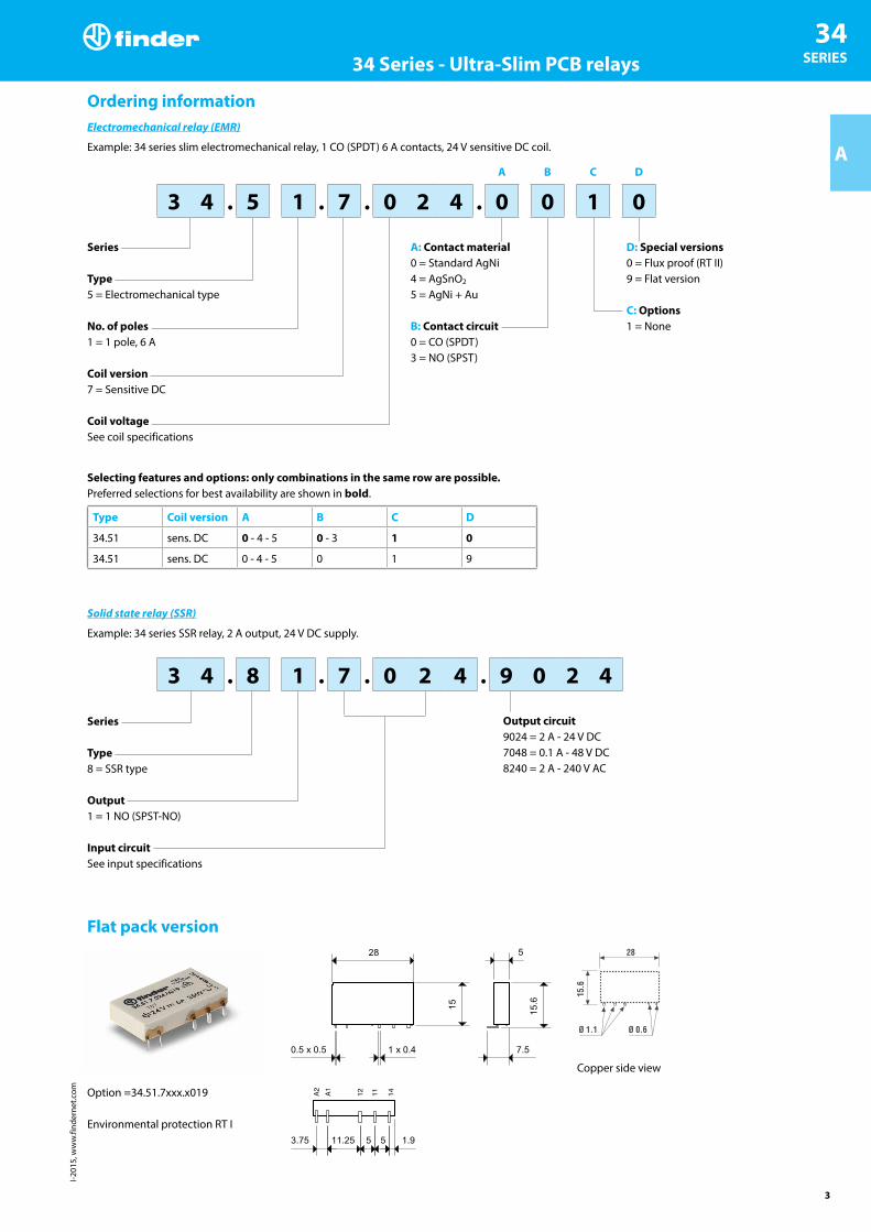
Ordering informationElectromechanical relay (EMR)
Example: 34 series slim electromechanical relay, 1 CO (SPDT) 6 A contacts, 24 V sensitive DC coil.
A B C D
3 4 . 5 1 . 7 . 0 2 4 . 0 0 1 0
Series
Type5 = Electromechanical type
No. of poles1 = 1 pole, 6 A
Coil version7 = Sensitive DC
Coil voltageSee coil specifications
A: Contact material0 = Standard AgNi 4 = AgSnO2
5 = AgNi + Au
B: Contact circuit0 = CO (SPDT)3 = NO (SPST)
D: Special versions0 = Flux proof (RT II)9 = Flat version
C: Options1 = None
Selecting features and options: only combinations in the same row are possible.Preferred selections for best availability are shown in bold.
Type Coil version A B C D
34.51 sens. DC 0 - 4 - 5 0 - 3 1 0
34.51 sens. DC 0 - 4 - 5 0 1 9
Solid state relay (SSR)
Example: 34 series SSR relay, 2 A output, 24 V DC supply.
3 4 . 8 1 . 7 . 0 2 4 . 9 0 2 4
Series
Type8 = SSR type
Output1 = 1 NO (SPST-NO)
Input circuitSee input specifications
Output circuit9024 = 2 A - 24 V DC7048 = 0.1 A - 48 V DC8240 = 2 A - 240 V AC
Flat pack version
Copper side view
Option =34.51.7xxx.x019
Environmental protection RT I
141112A1A2

I-201
5, w
ww
.find
erne
t.com
34 SERIES 34 Series - Ultra-Slim PCB relays
4
A
Electromechanical relay
Technical dataInsulation according to EN 61810-1
Nominal voltage of supply system V AC 230/400
Rated insulation voltage V AC 250 400
Pollution degree 3 2
Insulation between coil and contact set
Type of insulation Reinforced
Overvoltage category III
Rated impulse voltage kV (1.2/50 μs) 6
Dielectric strength V AC 4000
Insulation between open contacts
Type of disconnection Micro-disconnection
Dielectric strength V AC/kV (1.2/50 μs) 1000/1.5
Conducted disturbance immunity
Burst (5…50)ns, 5 kHz, on A1 - A2 EN 61000-4-4 level 4 (4 kV)
Surge (1.2/50 μs) on A1 - A2 (differential mode) EN 61000-4-5 level 3 (2 kV)
Other data
Bounce time: NO/NC ms 1/6
Vibration resistance (5…55)Hz: NO/NC g 10/5
Shock resistance g 20/14
Power lost to the environment without contact current W 0.2
with rated current W 0.5
Recommended distance between relays mounted on PCB mm ≥ 5
Contact specificationF 34 - Electrical life (AC) v contact current H 34 - Maximum DC1 breaking capacity
Cycl
es
Resistive load - cosφ = 1Inductive load - cosφ = 0.4
DC
brea
king
cur
rent
(A)
DC voltage (V)
• When switching a resistive load (DC1) having voltage and current values under the curve, an electrical life of ≥ 60 · 103 can be expected.
• In the case of DC13 loads, the connection of a diode in parallel with the load will permit a similar electrical life as for a DC1 load.Note: the release time for the load will be increased.
Coil specificationsDC coil data R 34 - DC coil operating range v ambient temperature
Nominal voltage
Coil code Operating range Resistance Rated coil consumption
UN Umin Umax R I at UN
V V V Ω mA
5 7.005 3.5 7.5 130 38.4
12 7.012 8.4 18 840 14.2
24 7.024 16.8 36 3350 7.1
48 7.048 33.6 72 12300 3.9
60 7.060 42 90 19700 3
1 - Max. permitted coil voltage.2 - Min. pick-up voltage with coil at ambient temperature.

I-201
5, w
ww
.find
erne
t.com
34 SERIES34 Series - Ultra-Slim PCB relays
5
A
Solid state relay
Technical data
EMC specifications Reference standard
Electrostatic discharge contact discharge EN 61000-4-2 4 kV
air discharge EN 61000-4-2 8 kV
Fast transients on supply terminals (burst 5/50 ns, 5 kHz) EN 61000-4-4 2 kV
Voltage pulses on supply terminals (surge 1.2/50 μs)
common mode EN 61000-4-5 0.5 kV
differential mode EN 61000-4-5 0.5 kV
Other data
Power lost to the environment without output current W 0.17
with rated current W 0.4
Input specificationInput data - DC types
Nominal voltage
Input code
Operating range Release voltage
Impedance Control current
UN Umin Umax I at UN
V V V V Ω mA
5 7.005 3.5 12 (10*) 1 715 (416*) 7 (12*)
12 7.012 8 17 4 1940 7.2
24 7.024 16 30 10 3200 7
60 7.060 35 72 20 21300 3
* AC Output version.
Output specificationL 34 - Output current v ambient temperature
SSR - 2 A DC & AC output typesL 34 - Output current v ambient temperature
SSR - 0.1 A DC output types
Out
put c
urre
nt
Out
put c
urre
nt
Outline drawingsType 34.51 Type 34.81

I-201
5, w
ww
.find
erne
t.com
34 SERIES 93 Series - Sockets and accessories for 34 series relays
6
A
93.61
93.62
93.63
93.64
93.68
Approvals (according to type):
Screw terminal socket 35 mm rail mounting (EN 60715)Common features- Space saving 6.2 mm wide- Connections for 16-way jumper link- Integral coil indication and protection circuit- Secure retention and easy ejection by plastic clip- Dual screw head (blade+cross) terminals
For technical data and supply versions, refer to the MasterINTERFACE 39 Series – “Relay interface module”
Electromechanical Relay - EMRSocket type (reference with the 39 Series)
Supply voltage Relay typeMasterBASIC
(39.11.....)MasterPLUS
(39.31.....)MasterINPUT
(39.41.....)MasterOUTPUT
(39.21.....)MasterTIMER
(39.81.....)6 V AC/DC 34.51.7.005.xx10 93.61.7.024 93.63.7.024 93.64.7.024 93.62.7.024 —
12 V AC/DC 34.51.7.012.xx10 93.61.7.024 93.63.7.024 93.64.7.024 93.62.7.024 93.68.0.02424 V AC/DC 34.51.7.024.xx10 93.61.7.024 93.63.7.024 93.64.7.024 93.62.7.024 93.68.0.02460 V AC/DC 34.51.7.060.xx10 — 93.63.7.060 — — —
(110…125)V AC/DC* 34.51.7.060.xx10 — 93.63.3.125 — — —(220…240)V AC* 34.51.7.060.xx10 — 93.63.3.230 — — —
(110…125)V AC/DC 34.51.7.060.xx10 93.61.0.125 93.63.0.125 93.64.0.125 93.62.0.125 —(24…240)V AC/DC 34.51.7.024.xx10 — 93.63.0.240 — — —
(220…240)V AC 34.51.7.060.xx10 93.61.8.230 93.63.8.230 93.64.8.230 93.62.8.230 —(110…125)V DC 34.51.7.060.xx10 — 93.63.7.125 — — —
220 V DC 34.51.7.060.xx10 — 93.63.7.220 — — —* Leakage current suppression
Solid State Relay - SSRSocket type (reference with the 39 Series)
Supply voltage Relay typeMasterBASIC
(39.10.....)MasterPLUS
(39.30.....)MasterINPUT
(39.40.....)MasterOUTPUT
(39.20.....)MasterTIMER
(39.80.....)12 V AC/DC 34.81.7.012.xxxx — — — — 93.68.0.02424 V AC/DC 34.81.7.024.xxxx — 93.63.0.024 93.64.0.024 — 93.68.0.024
(110…125)V AC/DC* 34.81.7.060.xxxx — 93.63.3.125 — — —(220…240)V AC* 34.81.7.060.xxxx — 93.63.3.230 — — —
(110…125)V AC/DC 34.81.7.060.xxxx 93.61.0.125 93.63.0.125 93.64.0.125 93.62.0.125 —(24…240)V AC/DC 34.81.7.024.xxxx — 93.63.0.240 — — —
(220…240)V AC 34.81.7.060.xxxx 93.61.8.230 93.63.8.230 93.64.8.230 93.62.8.230 —6 V DC 34.81.7.005.xxxx 93.61.7.024 93.63.7.024 93.64.7.024 93.62.7.024 —
12 V DC 34.81.7.012.xxxx 93.61.7.024 93.63.7.024 93.64.7.024 93.62.7.024 —24 V DC 34.81.7.024.xxxx 93.61.7.024 93.63.7.024 93.64.7.024 93.62.7.024 —60 V DC 34.81.7.060.xxxx — 93.63.7.060 — — —
(110…125)V DC 34.81.7.060.xxxx — 93.63.7.125 — — —220 V DC 34.81.7.060.xxxx — 93.63.7.220 — — —
* Leakage current suppression
Accessories16-way jumper link 093.16 (blue), 093.16.0 (black), 093.16.1 (red)Dual-purpose plastic separator 093.60Sheet of marker tags 060.72Technical dataRated values 6 A - 250 VDielectric strength 6 kV (1.2/50 μs) between coil and contactsProtection category IP 20Ambient temperature °C −40…+70Screw torque Nm 0.5Wire strip length mm 10Max wire size Solid wire and stranded wire
mm2 1 x(0.2…2.5) / 2 x 1.5AWG 1 x (24…14) / 2 x 16
I-201
5, w
ww
.find
erne
t.com
34 SERIES93 Series - Sockets and accessories for 34 series relays
7
A
93.60
93.65
93.66
93.67
93.69
Approvals (according to type):
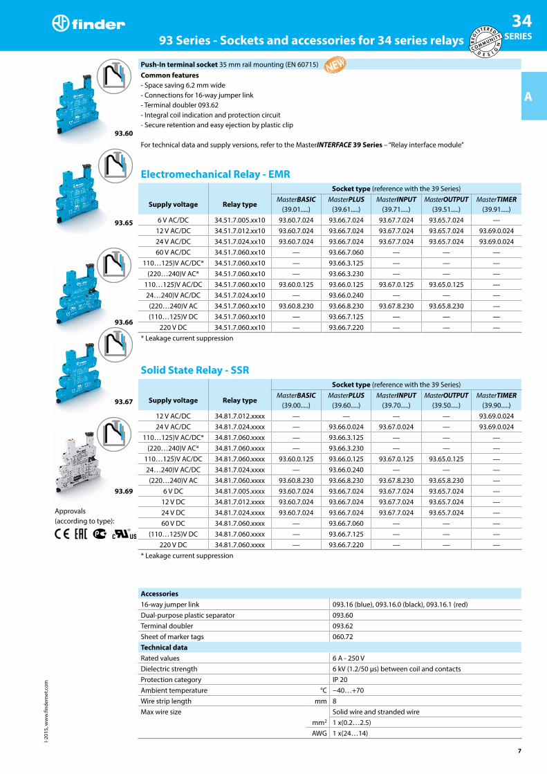
Push-In terminal socket 35 mm rail mounting (EN 60715)Common features- Space saving 6.2 mm wide- Connections for 16-way jumper link- Terminal doubler 093.62- Integral coil indication and protection circuit- Secure retention and easy ejection by plastic clip
For technical data and supply versions, refer to the MasterINTERFACE 39 Series – “Relay interface module”
Electromechanical Relay - EMRSocket type (reference with the 39 Series)
Supply voltage Relay typeMasterBASIC
(39.01.....)MasterPLUS
(39.61.....)MasterINPUT
(39.71.....)MasterOUTPUT
(39.51.....)MasterTIMER
(39.91.....)6 V AC/DC 34.51.7.005.xx10 93.60.7.024 93.66.7.024 93.67.7.024 93.65.7.024 —
12 V AC/DC 34.51.7.012.xx10 93.60.7.024 93.66.7.024 93.67.7.024 93.65.7.024 93.69.0.02424 V AC/DC 34.51.7.024.xx10 93.60.7.024 93.66.7.024 93.67.7.024 93.65.7.024 93.69.0.02460 V AC/DC 34.51.7.060.xx10 — 93.66.7.060 — — —
110…125)V AC/DC* 34.51.7.060.xx10 — 93.66.3.125 — — —(220…240)V AC* 34.51.7.060.xx10 — 93.66.3.230 — — —
110…125)V AC/DC 34.51.7.060.xx10 93.60.0.125 93.66.0.125 93.67.0.125 93.65.0.125 —24…240)V AC/DC 34.51.7.024.xx10 — 93.66.0.240 — — —(220…240)V AC 34.51.7.060.xx10 93.60.8.230 93.66.8.230 93.67.8.230 93.65.8.230 —(110…125)V DC 34.51.7.060.xx10 — 93.66.7.125 — — —
220 V DC 34.51.7.060.xx10 — 93.66.7.220 — — —* Leakage current suppression
Solid State Relay - SSRSocket type (reference with the 39 Series)
Supply voltage Relay typeMasterBASIC
(39.00.....)MasterPLUS
(39.60.....)MasterINPUT
(39.70.....)MasterOUTPUT
(39.50.....)MasterTIMER
(39.90.....)12 V AC/DC 34.81.7.012.xxxx — — — — 93.69.0.02424 V AC/DC 34.81.7.024.xxxx — 93.66.0.024 93.67.0.024 — 93.69.0.024
110…125)V AC/DC* 34.81.7.060.xxxx — 93.66.3.125 — — —(220…240)V AC* 34.81.7.060.xxxx — 93.66.3.230 — — —
110…125)V AC/DC 34.81.7.060.xxxx 93.60.0.125 93.66.0.125 93.67.0.125 93.65.0.125 —24…240)V AC/DC 34.81.7.024.xxxx — 93.66.0.240 — — —(220…240)V AC 34.81.7.060.xxxx 93.60.8.230 93.66.8.230 93.67.8.230 93.65.8.230 —
6 V DC 34.81.7.005.xxxx 93.60.7.024 93.66.7.024 93.67.7.024 93.65.7.024 —12 V DC 34.81.7.012.xxxx 93.60.7.024 93.66.7.024 93.67.7.024 93.65.7.024 —24 V DC 34.81.7.024.xxxx 93.60.7.024 93.66.7.024 93.67.7.024 93.65.7.024 —60 V DC 34.81.7.060.xxxx — 93.66.7.060 — — —
(110…125)V DC 34.81.7.060.xxxx — 93.66.7.125 — — —220 V DC 34.81.7.060.xxxx — 93.66.7.220 — — —
* Leakage current suppression
Accessories16-way jumper link 093.16 (blue), 093.16.0 (black), 093.16.1 (red)Dual-purpose plastic separator 093.60Terminal doubler 093.62Sheet of marker tags 060.72Technical dataRated values 6 A - 250 VDielectric strength 6 kV (1.2/50 μs) between coil and contactsProtection category IP 20Ambient temperature °C −40…+70Wire strip length mm 8Max wire size Solid wire and stranded wire
mm2 1 x(0.2…2.5)AWG 1 x(24…14)

I-201
5, w
ww
.find
erne
t.com
34 SERIES 93 Series - Sockets and accessories for 34 series relays
8
A
93.51
Approvals (according to type):
Certain relay/socket combinations
Screw less terminal socket 35 mm rail mounting (EN 60715)Common features- Space saving 6.2 mm wide- Connections for 20-way jumper link- Integral coil indication and protection circuit- Secure retention and easy ejection by plastic clip
For technical data and supply versions, refer to the 38 Series – “Relay interface module”
Electromechanical Relay - EMR and Solid State Relay - SSRRelay type (reference with the 38 Series)
Supply voltageElectromechnanical relay - EMR
(38.61.....)Solid State Relay - SSR
(38.81.....)Socket type
12 V AC/DC 34.51.7.012.xx10 — 93.51.0.02424 V AC/DC 34.51.7.024.xx10 — 93.51.0.024
110…125)V AC/DC 34.51.7.060.xx10 34.81.7.060.xxxx 93.51.0.125220…240)V AC/DC 34.51.7.060.xx10 34.81.7.060.xxxx 93.51.0.240110…125)V AC/DC* 34.51.7.060.xx10 34.81.7.060.xxxx 93.51.3.125
(220…240)V AC* 34.51.7.060.xx10 34.81.7.060.xxxx 93.51.3.240(220…240)V AC 34.51.7.060.xx10 34.81.7.060.xxxx 93.51.8.240
12 V DC 34.51.7.012.xx10 34.81.7.012.xxxx 93.51.7.02424 V DC 34.51.7.024.xx10 34.81.7.024.xxxx 93.51.7.02460 V DC 34.51.7.060.xx10 34.81.7.060.xxxx 93.51.7.060
* Leakage current suppression
Accessories20-way jumper link 093.20Plastic separator 093.01Sheet of marker tags 093.64Technical dataRated values 6 A - 250 VDielectric strength 6 kV (1.2/50 μs) between coil and contactsProtection category IP 20Ambient temperature (UN ≤ 60 V/> 60 V) °C −40…+70/−40…+55Wire strip length mm 10Max wire size Solid wire and stranded wire
mm2 1 x 2.5 / 2 x 1.5AWG 1 x 14 / 2 x 16

I-201
5, w
ww
.find
erne
t.com
34 SERIES93 Series - Sockets and accessories for 34 series relays
9
A 93.11
Approvals (according to type):
PCB socket with retaining and release clip 93.11 (blue)For relay type 34.51, 34.81Technical dataRated values 6 A - 250 VDielectric strength ≥ 6 kV (1.2/50 μs) between coil and contactsProtection category IP 20Ambient temperature °C –40…+70
Retaining and release clip use: