3.4 Packet Filtering for Network Intrusion Detection
123
A real time packet filtering module for network intrusion detection system by Guang Yang A thesis submitted to the graduate faculty in partial fulfillment of the requirements for the degree of MASTER OF SCIENCE Major: Computer Science Major Professor: R. C. Sekar
Transcript of 3.4 Packet Filtering for Network Intrusion Detection

A real time packet filtering module
for network intrusion detection system
by
Guang Yang
A thesis submitted to the graduate faculty
in partial fulfillment of the requirements for the degree of
MASTER OF SCIENCE
Major: Computer Science
Major Professor: R. C. Sekar
Iowa State University
Ames, Iowa
1998

Graduate CollegeIowa State University
This is to certify that the Master’s thesis of
Guang Yang
has met the thesis requirements of Iowa State University
________________________________
Major Professor
________________________________
For the Major Program
________________________________
For the Graduate College
ii

TABLE OF CONTENTS
ABSTRACT..............................................................................................................................v
CHAPTER 1. INTRODUCTION...........................................................................................1
1.1 Network Security and Potential Threats...........................................................................11.2 Intrusion Detection...........................................................................................................21.3 Key Contributions............................................................................................................31.4 Thesis Organization..........................................................................................................3
CHAPTER 2. OVERVIEW OF TCP/IP BASED NETWORK INTRUSION...................5
2.1 TCP/IP Basics...................................................................................................................52.1.1 Protocol Hierarchy.....................................................................................................52.1.2 IP................................................................................................................................52.1.3 UDP............................................................................................................................72.1.4 TCP............................................................................................................................7
2.2 Common Vulnerabilities..................................................................................................92.2.1 IP Source Address Spoofing......................................................................................92.2.2 TCP Sequence Number Prediction............................................................................92.2.3 Port Scanning...........................................................................................................10
2.3 Network Intrusions.........................................................................................................112.3.1 Denial of Service......................................................................................................11
2.3.1.1 CHARGEN and ECHO.....................................................................................122.3.1.2 SYN Flooding....................................................................................................122.3.1.3 Other Denial of Service Intrusions....................................................................15
2.3.2 Spoofing...................................................................................................................162.3.2.1 Client-Side Spoofing.........................................................................................162.3.2.2 Server-Side Spoofing.........................................................................................18
2.3.3 Service Specific Intrusions.......................................................................................192.3.3.1 Finger Daemon Attack.......................................................................................192.3.3.2 Routing Infrastructure Intrusions.......................................................................202.3.3.3 DNS Misuse.......................................................................................................202.3.3.4 NFS....................................................................................................................222.3.3.5 X-Windows........................................................................................................23
CHAPTER 3. INTRUSION DETECTION AND PACKET FILTERING......................24
3.1 Current Techniques in Network Security.......................................................................243.1.1 Audit Trails..............................................................................................................243.1.2 Firewall....................................................................................................................25
3.1.2.1 Screening Router...............................................................................................253.1.2.2 Application Gateway.........................................................................................26
3.2 Packet Filtering...............................................................................................................27
iii

3.2.1 General Issues..........................................................................................................283.2.2 Existing Packet-Filtering Systems...........................................................................28
3.2.2.1 Linux SOCK_PACKET.....................................................................................283.2.2.2 Data Link Provider Interface.............................................................................293.2.2.3 BSD Packet Filter..............................................................................................29
3.2.3 Packet Capture Library............................................................................................313.3 Bro: An Intrusion Detection System Based on Packet Filtering....................................32
3.3.1 Bro Architecture.......................................................................................................323.3.2 Bro Language...........................................................................................................33
3.4 Packet Filtering for Network Intrusion Detection..........................................................35
CHAPTER 4. INTRUSION PATTERN SPECIFICATION LANGUAGE.....................37
4.1 ASL Syntax....................................................................................................................374.2 Packet Structure Description..........................................................................................374.3 Constraint Checking.......................................................................................................394.4 Sample Patterns..............................................................................................................41
CHAPTER 5. SYSTEM DESIGN AND IMPLEMENTATION.......................................43
5.1 System Architecture.......................................................................................................435.2 Packet Offset Calculation...............................................................................................445.3 Filter Model for Single Rule..........................................................................................455.4 Filter Integration.............................................................................................................475.5 Rule Preprocessing.........................................................................................................51
5.5.1 Rule Decomposition.................................................................................................515.5.2 Constraint Stack Construction.................................................................................52
5.6 Automaton Construction................................................................................................545.6.1 Offset Selection........................................................................................................545.6.2 Sub-Automaton Sharing...........................................................................................56
5.7 Code Generation.............................................................................................................575.8 Data Generation..............................................................................................................59
CHAPTER 6. EXPERIMENTAL RESULTS AND CONCLUSION...............................62
6.1 Intrusion Detection Using ASL......................................................................................626.2 Preliminary Performance Testing...................................................................................63
6.2.1 SRVSTAT: Service Statistics..................................................................................636.2.2 Performance Comparison: ASL vs. BPF.................................................................64
6.3 Conclusion......................................................................................................................65
APPENDIX A PACKET DATA STRUCTURES FOR ASL.............................................67
APPENDIX B INTRUSION PATTERN SAMPLES.........................................................72
REFERENCES......................................................................................................................75
iv
ACKNOWLEDGEMENTS..................................................................................................77
ABSTRACT
Computer networks bring us not only the benefits, such as more computing power
and better performance for a given price, but also some challenges and risks, especially in the
field of system security. During the past two decades, significant effort has been put into
network security research and several techniques have been developed for building secure
networks. Packet filtering plays an important role in many security-related techniques, such
as intrusion detection, access control and firewall. A packet-filtering system constitutes the
first line of defense in a computer network environment. The key issues in the packet-
filtering technique are efficiency and flexibility. The efficiency refers to the ability of a filter
to quickly capture network packets of interest, while the flexibility means the filter can be
customized easily for different packet patterns.
In this thesis, we present a real-time packet-filtering module, which can be integrated
into a large-scale network intrusion detection system. The core of this packet-filtering
module is a rule-based specification language ASL (Auditing Specification Language),
which is used in describing the packet patterns and reactions for a network intrusion
detection system. The important features of ASL that are not provided by other packet-
filtering systems are protocol independence and type safety. ASL provides a number of new
features that distinguish it from other languages used for intrusion detection and packet
filtering, such as packet structure description and protocol constraint checking.
We develop the algorithms and heuristics for constructing fast packet filter from ASL
specifications. Our algorithms improve upon existing techniques in that the performance of
the generated filters is insensitive to the number of rules. We discuss implementation of
these algorithms and present experimental results.
v

CHAPTER 1. INTRODUCTION
Computation models have experienced a significant change since the emergence of
computer networks, which allow heterogeneous computers to communicate with each other.
During the past two decades, most centralized systems have been replaced by a number of
interconnected computers. This factor has led to more computing power, increased
flexibility and better performance/price ratio.
However, at the same time, we also face many new challenges and risks with
networked computing, such as lack of communication reliability, coordination, resource
management, and so on. As more and more computer networks are brought into electronic
commence, transaction management, and even national defense, people begin to pay
increasing attention to system security.
1.1 Network Security and Potential Threats
There are a number of security issues for a computer network environment [1]:
Availability: The system must be functional and correctly provide services.
Confidentiality: The data transmitted from one system to the other must be
accessible only for the authorized parties.
Authentication: The identity associated with the data must be correct. The
identity can apply to a user, host or software component.
Integrity: The data being processed or transmitted can be modified only by the
authorized parties.
Non-repudiation: Neither the sender nor the receiver of data is able to deny the
fact of data transmission.
1

A system that meets the above criteria can be considered as a secure computer
network system. A hacker who wants to attack a network, thus thinks of ways to
compromise the above criteria [1]:
Interruption: Destroy a system or make it unavailable or unusable.
Interception: Obtain unauthorized access to data.
Modification: Compromise data integrity, e.g. modify messages sent from one
system to another.
1.2 Intrusion Detection
As defined by Heady et al. [2], an intrusion is
any set of actions that attempt to comprise the integrity, confidentiality or availability
of a resource.
Intrusion leads to violations of the security policies of a computer system, such as
unauthorized access to private information, malicious break-in into a computer system, or
rendering a system unreliable or unusable.
A full-blown network security system should include the following subsystems:
Intrusion Detection Subsystem: Distinguishes a potential intrusion from a valid
network operation.
Protection Subsystem: Protects the network and security system itself from being
compromised by the network intrusions.
Reaction Subsystem: This part either traces down the origin of an intrusion or
fights back the hackers.
The focus of this thesis is on the intrusion detection subsystem, which constitutes the
first line of defense for a computer network system. There are a number of approaches in
this field. Most of them fall into three primary categories: anomaly detection, misuse
detection and hybrid schemes.
The anomaly detection approach is based on a model of normal activities in the
system. This model can either be predefined or established through techniques such as
machine learning. Once there is a significant deviation from this model, an anomaly will be
2

reported. By contrast, a misuse detection approach defines specific user actions that
constitute a misuse and uses rules for encoding and detecting known intrusions [3]. The
hybrid detection approach uses a combination of anomaly and misuse detection techniques.
1.3 Key Contributions
Packet filtering is a critical technique in network management, firewall strategy and
intrusion detection. However, the existing packet filtering systems have a number of
limitations in system efficiency, flexibility and scalability. For instance, a packet filter for
one protocol suite can not be easily changed to fit for another protocol suite. In addition,
most packet filters suffer from significant performance degradation as the number of packet
patterns increases.
In this thesis, we present a novel approach for constructing a real-time packet-
filtering module that can be used for network intrusion detection purpose. One of the main
contributions in our approach is a specification language designed for describing intrusion
patterns and reactions. This language provides a number of features that distinguish it from
other specification languages used for intrusion detection or packet filtering, such as protocol
independence and type safety. Another important focus of our work is the development of
fast pattern-matching algorithms (for packet filter) that are insensitive to the number of
patterns.
1.4 Thesis Organization
In chapter 2, we give a brief review of TCP/IP (Transmission Control
Protocol/Internet Protocol) protocol suite and several security holes in the design and
implementation of TCP/IP. Chapter 3 surveys some existing techniques in building a secure
computer network system. We also discuss some general issues on packet filtering that is
one of the main techniques in network intrusion detection. In chapter 4, we give a detailed
description of our specification language and its application to intrusion detection. Chapter 5
discusses the issues in the design and implementation of our packet-filtering module. The
primary concern is to reduce the processing time of a packet filter. In the last chapter, we
3

provide some experimental results from performance testing of our packet filter and
summarize our work.
4

CHAPTER 2. OVERVIEW OF TCP/IP BASED NETWORK INTRUSION
TCP/IP is the common language used in the world of computer networks.
Nevertheless, there exist several security flaws in the protocol design or implementation of
TCP/IP. As a result, network hackers, who intend to compromise the target network systems
by exploiting these security holes, have invented various intrusion methods.
2.1 TCP/IP Basics
Developed under the sponsorship from DARPA (Defense Advanced Research
Projects Agency), TCP/IP is the most widely used communication protocol suite today. It is
the de facto standard employed to interconnect computing facilities in modern network
environments.
2.1.1 Protocol Hierarchy
TCP/IP is designed through a layered approach, with each layer responsible for a
different facet of communication [4]. This hierarchical architecture makes each protocol
layer possible to evolve independently without affecting the adjacent layers. In addition, data
encapsulation is achieved through various headers among different transportation layers like
IP header, TCP header or other application headers as shown in Figure 2.1. These headers
are important in keeping the state information for each network connection and facilitating
multiplexing and de-multiplexing of transmission messages.
2.1.2 IP
IP is the workhorse protocol of the TCP/IP protocol suite. It provides an unreliable,
connectionless datagram delivery service. All the TCP, UDP (User Datagram Protocol),
5

Figure 2.1 TCP/IP Protocol Hierarchy
ICMP (Internet Control Message Protocol), and IGMP (Internet Group Management
Protocol) data are transmitted as IP datagrams [4].
An IP header has the information like source IP address and destination IP address,
which plays an important role in routing a packet around the networks. A detailed
description of IP header can be found in [4]. Figure 2.2 shows the structure of a normal IP
header.
Figure 2.2 IP Header
user data
Appl. header user data
IP header TCP header application data
TCP header application data
Ether header IP header TCP header application data Ether trailer
version length type of service total length
identification flags fragment offset
time to live protocol header checksum
source IP address
destination IP address
options (if any)
data
6

Delivering a packet to the correct destination is non-trivial, especially in a large-scale
network system. Each intermediate routing device makes best effort to deliver the IP packet,
but there is no guarantee that it will reach the destination finally. So, a packet can be lost,
duplicated, or delivered out of order [4]. It is the task of higher layer protocols to correct
such errors.
2.1.3 UDP
UDP is a transport layer protocol, but it does not offer much functionality over and
above that of IP. The port numbers in UDP header identify the sending process and the
receiving process [4], while the checksum provides a limited ability for error detection
(Figure 2.3).
Figure 2.3 UDP Header
However, due to its simplicity and low overhead compared to connection-oriented
protocols, UDP is suitable for the design of simple request/reply application protocol, such as
DNS (Domain Name System), SNMP (Simple Network Management Protocol), and so on.
2.1.4 TCP
TCP is built on top of the IP layer, which is unreliable and connectionless. But TCP
provides the higher layer application a reliable connection-oriented service. As the tradeoff,
each TCP connection requires an establishment procedure and a termination step between
communication peers. TCP also provides sequencing and flow control.
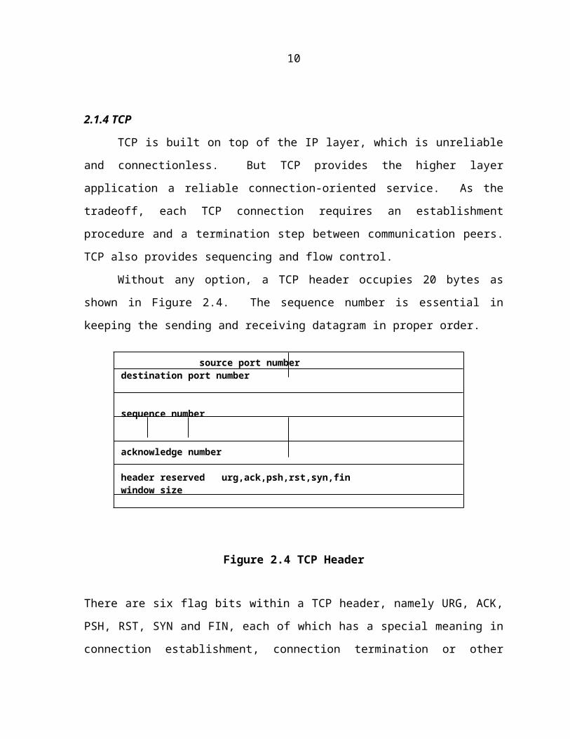
Without any option, a TCP header occupies 20 bytes as shown in Figure 2.4. The
sequence number is essential in keeping the sending and receiving datagram in proper order.
source port number destination port number
UDP length UDP checksum
data
7

Figure 2.4 TCP Header
There are six flag bits within a TCP header, namely URG, ACK, PSH, RST, SYN and FIN,
each of which has a special meaning in connection establishment, connection termination or
other control phases. Window size, which specifies how many bytes of data can be accepted
each time by the receiving side, is advertised between the two communication peers for the
purpose of flow control.
TCP establishes a connection in three steps, commonly known as a three-way
handshake. Figure 2.5 shows a typical three-way handshake procedure between a source
host S and a destination host D.
SYNISNs
SYNISNd, ACKISNs+1
ACKISNd+1
Figure 2.5 Three-Way Handshake
source port number destination port number
sequence number
acknowledge number
header reserved urg,ack,psh,rst,syn,fin window size
TCP checksum urgent pointer
options (if any)
data (if any)
S D
8

First, S sends a SYN packet to D in order to establish a connection. Meanwhile, S
sets its own ISN (Initial Sequence Number) in sequence number field of the packet. Upon
receiving the request packet, D sends back a SYN_ACK packet as the acknowledgement
including its own ISN and the incremented ISN from S. As the acknowledgement packet
reaches the source host S, S immediately transmits an ACK packet back to D. In the last
ACK packet, S needs to include the incremented ISN of D as the confirmation of the
connection. At this point, the connection has been setup. There is one extra point that needs
to be mentioned: suppose that host S does not send any SYN packet but received a
SYN_ACK packet from host D, it will then send back a RST packet to reset the connection.
2.2 Common Vulnerabilities
During the past two decades, many security problems of TCP/IP protocol suite have
been discovered. Meanwhile, the network hackers created a large number of intrusion
methods to exploit those vulnerabilities. Most of the examples in this section are taken from
Bellovin’s excellent paper on TCP/IP security [5].
2.2.1 IP Source Address Spoofing
As we have seen from the previous section, the IP address (either source address or
destination address) contained in an IP header is the only information needed by an
intermediate routing device to make a decision on how to route the IP packet. So, anyone
who has access to the IP layer can easily modify the source address in the IP header of a
packet, spoofing itself as from another host or even from a non-existing host.
2.2.2 TCP Sequence Number Prediction
From the three-way handshake, we know that to establish a TCP connection between
two communication peers, the source host must obtain the ISN of the destination host from
its acknowledgement packet. Usually, an ISN is more or less a random number [5].
If a hacker can predict the ISN, he/she can impersonate host S by sending a request
packet with the IP source address changed to S. Although the hacker will not get the
9

SYN_ACK packet sent by D, he/she can still finish the establishment process by sending
back an ACK packet to host D with predicted ISN. As shown in Figure 2.6, ISNg represents
the guessed ISN of host D by the hacker.
In Berkeley systems, the initial sequence number is incremented by a constant
number (128 in 4.2BSD and 125,000 in 4.3BSD) once per second and by half that number
each time a connection is initiated [6]. Thus, what a hacker needs to do is just to initiate a
normal connection and remember the ISN received from the destination host. After that, the
hacker could calculate the ISN for the next connection attempt, based on the round-trip delay
and the number of connections after the first connection. This approach has a high
probability of succeeding.
Figure 2.6 TCP Sequence Number Prediction
2.2.3 Port Scanning
Strictly speaking, port scanning is not a technique used directly to perform an
intrusion. Instead, its goal is to discover an exploitable communication channel and then
launch the real attack. The reason for doing port scanning is that some vulnerable services
may not use a fixed port number. As in the SUN NFS system, some application servers run
at an arbitrary port and register the port number to a specific server, which is called directory
server. For the client programs of a particular application server, they need to first check
with the directory server to obtain the port number for that application server. Usually, the
directory server is well protected. So, a hacker needs another way to locate his victim.
There are several methods that can be used to detect a potential communication
channel. For a listening TCP server, the most elementary approach is to make a real
connection. The UNIX system-call connect can be used to open a connection with every
port that the hacker intends to examine. If there is a listening server, the connect call will
X D: SYN(ISNx), SRC = S
D S: SYN(ISNd), ACK(ISNx)
X D: ACK(ISNg), SRC = S
10

succeed. Otherwise the port is unused. Another method is through SYN scanning, in which
a SYN packet is sent to the victim as if it is going to create a real connection. As mentioned
in TCP three-way handshake, a returned SYN_ACK or RST packet indicates the presence or
absence of an active server on the port. Another variant of this approach is TCP FIN
scanning. Instead of sending SYN probes like in SYN scanning, this method sends FIN
packet and waits for a RST packet from a closed port. In case of an active listener, it will
discard the FIN packet silently without sending anything back.
Unlike TCP, UDP is a connectionless protocol, whose simplicity makes port scanning
more difficult. Since UDP does not require a three-way handshake to establish a connection,
a UDP server does not need to acknowledge any probe packets. Also, no error messages are
returned for closed ports. However, most hosts send ICMP “port unreachable” message for a
packet intended for an unused UDP port. This gives hackers some clue. Since neither UDP
packets nor the ICMP messages are guaranteed to be delivered due to the unreliable nature of
the protocol itself, a port scanner needs to have some retransmission policy to ensure that lost
packets do not lead to erroneous results.
2.3 Network Intrusions
A number of network intrusions have been found till now, each of which utilizes one
or more security vulnerabilities in TCP/IP protocol specifications or implementations. These
intrusions include IP source address spoofing, TCP sequence number prediction as
mentioned earlier, and other intrusions like SYN flooding, DNS misuse, Ping of Death, or
some Java-related attacks. However, based on the intrusion patterns and impacts to the
victim systems, we can divide the intrusions into two main categories: denial of service and
spoofing.
2.3.1 Denial of Service
The lifeblood of today’s world is information [8]. The denial-of-service intrusions
attempt to prevent or delay access to the information or the information processing systems.
11

The basic idea behind this type of intrusion is to tie up a service provider with bogus requests
in order to render it unreliable or unusable.
2.3.1.1 CHARGEN and ECHO
CHARGEN is a simple service provided by almost all TCP/IP implementation under
UNIX. It runs on both UDP and TCP port 19. For every incoming UDP packet, the server
sends back a packet with 0 to 512 randomly selected characters. Another well-known service
is ECHO, which runs on UDP and TCP port 7. The server just responds to the client
program with whatever it receives.
These two services are normally used for the diagnostic purpose. However, they can
be employed by a malicious denial-of-service type intrusion. Assuming a “chain” has been
established between a CHARGEN service and an ECHO service, what will happen next?
Each of them will produce output continuously, leading to a huge number of packets among
the network and thus a denial of service on the machines where the services are provided.
Launching such an intrusion is surprisingly easy. A simple UDP packet could set the
whole network into trouble. Suppose there are two hosts A and B and a hacker on machine
X. With the help of IP source address spoofing, a hacker can send out a UDP packet to A
with B’s IP address as the source address and 7 as the source port, while setting the
destination IP address as A’s IP address and 19 as the destination port. When this packet is
received by A, A will falsely think that B is requiring the CHARGEN service, and sends
back a packet to B’s ECHO port. At this point, a “chain” has been established successfully.
Subsequently, large amount of traffic will be generated within the network where hosts A
and B reside. As a result, network users will feel an abrupt drop in the performance of their
network applications.
Generally speaking, CHARGEN and ECHO type of intrusion is a kind of blind
attack. There is no particular objective from a hacker’s point of view. The goal is to slow
down the speed of the whole network.
12
2.3.1.2 SYN Flooding
Unlike the simple CHARGEN and ECHO intrusion, SYN flooding is a specially
designed attack that employs a flood of SYN packets to consume the limited resource on the
targeted host. It results in delays to legitimate network connection requests and eventually
halts the service provider.
As in the TCP/IP implementations for UNIX, a number of memory structures need to
be allocated for each TCP connection request. Take BSD system as an example: a socket
structure is used to hold the communication elements (e.g. protocol being used), address
information, request queues, buffers and flags [4]. Moreover, there are two extra memory
structures with special meanings to a TCP connection, namely IP control block (inpcb) and
TCP control block (tcpcb), which keep the TCP state information, port numbers, sequence
numbers and several connection-related timers. Typically, these structures will use a few
hundred bytes of memory [7].
A normal scenario of a TCP connection process starts with a system in LISTEN state
receiving a SYN packet, which is to be examined for checksum immediately. If the
checksum is incorrect, the packet will be discarded silently, with the expectation that the
remote site will retransmit a new packet. Otherwise, the TCP control block associated with
this connection is searched for. If no such item is found, it means no server process is
waiting for this packet, and then the packet will be removed and an RST packet is returned to
inform the remote client. By contrast, if a server process is located, several memory
structures will then be allocated for this connection and a SYN_ACK packet will be sent
back as an acknowledgement to the sender to continue the three-way handshake. Meanwhile,
the system enters into the SYN_RECVD state and starts up a connection establishment timer.
The connection of this stage is always called a half-open connection. Most TCP/IP
implementations set the timer to expire after 75 seconds. If the final ACK packet arrives
before the timer expires, the request will leave kernel space and go to application space.
Otherwise, the three-way handshake fails. Under both cases, the corresponding memory
structures will be released from kernel space.
13

From the description above, we know that the process of TCP connection
establishment requires significant amount of work and resources at the server side. So, in
most systems, there is a limit on the total number of half-open connections. A hacker
exploits this limitation and initiates a SYN flooding attack by issuing a large number of
connection requests with a spoofed source IP address to the target host, which cannot tell a
malicious request from a legal request. After receiving the SYN packet, the target host will
respond with SYN_ACK packet as usual. Unfortunately, this time the final ACK packet will
never come back, for the request SYN packet has a spoofed source address and that address
is “unreachable” to the target host (Figure 2.7). There are several reasons for an IP address
to be “unreachable”. For instance, the machine with that IP address is turned down, or there
may be even no host with that IP address at all. Actually, there may be some error messages
like ICMP “host unreachable” or “network unreachable” generated by a router, coming back
during the time when the target host waits for the final ACK packet. But current
implementations of TCP/IP typically ignore such error messages. Before the timer used for
TCP connection establishment expires, the memory allocated for a connection request will
stay in the kernel. As large numbers of bogus connection requests come to the target host, it
will run out of kernel memory quickly. As a result, if there is no more memory structures
can be allocated for the following connection requests, they will be discarded silently.
S D
Spoofed SYN LISTEN
SYN_ACK SYN_RECVD
Figure 2.7 SYN Flooding
14

The key issue in this type of intrusion is how to choose an “unreachable” source IP
address for an attacking packet. There are several patterns followed by the hackers.
Single address: all the attacking packet using same IP address
Short list: there is a small pool of addresses for every outgoing packet to choose
No list: the source address is generated randomly
Different addressing method poses different challenges for an intrusion detection system.
The basis for this type of attack is that TCP/IP protocol suite does not provide strong
authentication on its control packet [9]. The endpoint of a connection has no way to
authenticate its communication peer. As a result, it is extremely difficult to trace the original
source of the spoofed IP packet. Therefore, a hacker can feel free to perform this kind of
intrusion without worrying about being tracked down.
2.3.1.3 Other Denial of Service Intrusions
Other forms of denial-of-service type intrusions also exist, like Ping of Death. Ping
of Death explores a bug in some TCP/IP implementations that cannot handle the fragmented
IP packet correctly. In this case, a hacker first breaks a normal packet into a series of
fragments, then modifies the last one and makes the total length of all fragments exceed the
maximum packet length specified in TCP/IP protocol. When the receiving host assembles
those fragments, it will overflow its buffer in the TCP/IP stack due to the abnormal size of
the arrived packet. As a result, system on that host will crash.
There are some intrusions, which utilize the broadcast property of transmission
media, are limited to a LAN (Local Area Network) environment, especially Ethernet.
However, we cannot overlook those intrusions. It is possible that some hosts are less secure
than other hosts on a LAN. A hacker can perform a multi-step intrusion by first breaking
into a less secure host and then compromise the whole network. One of the threats to a LAN
is called SYN_RST generator, which can block most of the TCP connections. Suppose that a
host A wants to make a TCP connection with host B, it will first send a SYN packet to B. If
host X also hears this message, because of the broadcast communication media, before B
responds with a SYN_ACK packet, X can quickly send out a RST packet to A, shutting
15

down the intended connection. Another intrusion example is one in which the flow control
mechanism of TCP communication is attacked. In order to prevent a fast sender from
overrunning the buffer of a slow receiver, each TCP packet has a window size for its
communication peer. During the communication process, a third party host can impersonate
the destination host, sending a packet with zero window size. Then, both communication
parties can be halted due to the lack of buffer advertised by the communication peer.
With the increasing use of Java in the web computing, intrusions by malicious Java
applets are another source of concern. Most of the applet intrusions fall into denial of
service, in which a Java applet consumes a lot of CPU and memory resources of the client
machine.
2.3.2 Spoofing
Spoofing is another important hacking technique in the network intrusions. Due to
the distributed nature of computer networks, the primary method used to exchange data
among different hosts is message passing. Therefore, strong authentication is not easy to
achieve compared to that in a traditional centralized system, especially among arbitrary
communication peers. A network hacker exploits this weakness and creates many intrusion
methods, either spoofing himself as a legitimate client or server.
2.3.2.1 Client-Side Spoofing
In client-side spoofing, a hacker impersonates himself as an authorized client and in
turn gains services from a server. An example is provided by the “r-utilities” on most UNIX
systems.
“R-utilities”, like rlogin, rsh and rcp, is a set of commands for remote operations
among different UNIX systems. The security hole underlying “r-utilities” is the
authentication scheme used by this set of commands.
Take “rlogin” as an example, which uses TCP as its transportation layer protocol and
is a simple client/server application. With two hosts A and B, each of which “trusts” the
other one, we can configure the file “/etc/hosts.equiv” or “.rhosts” on each host to let a user
with accounts on both hosts to login from one host to another without being prompted for a
16

password. In effect, the user is authenticated via the host name of the machine he/she is
currently logged on.
In 1995, CERT(TM) Coordination Center issued a security advisory addressed a kind
of intrusion called “IP Spoofing”, in which the hackers created packets with spoofed source
IP address, then exploited applications that use authentication based on IP address, like “r-
utilities” [7]. IP spoofing consists of several steps and uses both address spoofing and TCP
sequence number prediction. Following are two scenarios that can happen, one is a normal
“rlgoin” session, while the other is a spoofing intrusion (Figure 2.8).
Usually, IP Spoofing takes the following steps:
Figure 2.8 IP Spoofing
First, a victim host is selected and a pattern of trust is discovered, e.g. which hosts
the victim host trusts. In the example shown in Figure 2.8, the victim host is S,
while it trusts host C.
Normal Remote Login Session:
C S: SYN(ISNc)
S C: SYN(ISNs), ACK(ISNc)
C S: ACK(ISNs)
C S: data
S C: data
Spoofed Intrusion:
X S: SYN(ISNx), SRC = C
S C: SYN(ISNs), ACK(ISNx)
X S: ACK(ISNs), SRC = C
X S: ACK(ISNs), SRC = C, malicious messages
17

Then, C is “shut down”, either by SYN flooding that machine or by intercepting
the entire network traffic to it. Alternatively, the attack may be initiated when C
is down due to other reasons, such as maintenance.
Next, a normal TCP connection request packet is sent to the victim host S to get
back a valid sequence number. Based on the round-trip delay and the TCP
sequence number generating algorithm, a hacker could predict the next sequence
number that will be used by S.
At this point, S can be intruded upon. The hacker sends a SYN packet to S with
the trust host C as source IP address. Even though the SYN_ACK packet will not
return to the hacker, he/she can still finish the connection establishment by
sending out the final ACK packet with the guessed sequence number from the
previous step.
The victim host S all along concludes a valid connection request from trusted host
C. Then, the hacker could send data from host X.
One thing that needs to be clarified in this intrusion is, when the hacker from host X
masquerades himself as a trusted client and sends out a SYN packet, the returned SYN_ACK
packet from the victim host will go to the real host C. As mentioned in the previous chapter,
the host C will immediately respond with a RST packet and the intrusion will fail because the
intended connection will be shutdown when the victim host S received this packet.
Therefore, SYN flooding is always performed as a preparing step in “IP Spoofing”. As a
result, the returned SYN_ACK packet would not reach the destination host C but gets lost on
the way. The reason is that the host C is busy in dealing with large amounts of bogus
requests and runs out of system resources.
IP spoofing is a typical example of client-side spoofing intrusion. All the applications
with loose authentication mechanism based on IP address also face the threats from this type
of intrusion.
18

2.3.2.2 Server-Side Spoofing
Server-side spoofing employs a similar idea. However, the goals and the methods
used are a bit different. For the client-side spoofing, as we mentioned in the example of
“rlogin”, a hacker impersonates an authorized user and then gains data from an information
provider. By contrast, the server-side spoofing is executed in the reverse way. In order to
obtain confidential information from individual clients, a hacker masquerades as a real
service provider and steals sensitive information from service users.
The idea behind server-side spoofing intrusion can be properly expressed by a real
life example. Suppose that some one creates a machine that looks extremely like an ATM
but does not provide the real functionality of a normal ATM. Instead, it records the number
of an ATM card and its holder’s PIN (Personal Identification Number), then reports some
error message to mislead the user that this machine has temporary mechanical problem. If
such a machine were placed at the entrance of a shopping mall, the result would be
disastrous. A user may lose large amounts of money just because he/she once used an out-
of-order ATM several days before.
Same idea is employed in web spoofing. First step is to put some HTML (Hypertext
Makeup Language) links in some popular web pages. When a victim visits that page and
clicks that link, all the following connections is hijacked by a malicious server, which hides
itself between the user browser and the real web server. No sophisticated technique is used
in this attack. Some simple Java script applet, together with a little HTTP (Hypertext
Transfer Protocol) and CGI (Common Gateway Interface) knowledge, is sufficient to hijack
such connections. With the growing popularity of electronic commence, this type of
intrusion becomes even more dangerous. A malicious server can easily grab personal
information from a web shopper, such as credit card information.
2.3.3 Service Specific Intrusions
In this section, we survey some service specific intrusions, such as finger daemon
attack, routing infrastructure intrusion, DNS misuse and several attacks to NFS (Network
File System) or X-Windows system.
19

2.3.3.1 Finger Daemon Attack
All the intrusions discussed above were either attacks to the protocols themselves or
intrusions that result due to weak implementations of protocols. However, there are still a
number of intrusions that do not have much relation with communication systems. But we
could still detect their existence by examining the related network traffic.
The well-known Internet worm program fits into this category, which exploits some
flaws in several utility programs under UNIX systems. One problematic utility, which it
found, was fingerd. The fingerd program was intended to run as a daemon, or background
process, to service remote requests using finger protocol [6]. The fingerd used a system-call
gets, which does not check the length of the buffer used for reading. So, a hacker could
deliberately form a finger request to overwrite the buffer in fingerd, and this buffer overwrite
can be used to execute arbitrary command at the target system. A detailed description of this
attack can be found in [19]. Technically, this intrusion is a buffer overflow type of attack.
But we can still detect it by checking the network packets to a finger daemon, for a normal
request only has a small length of data, while a malicious intrusion packet contains a large
amount of data intending to overwrite the system buffer.
2.3.3.2 Routing Infrastructure Intrusions
As described at the beginning of this thesis, all the TCP/IP services are built on a
connectionless packet delivery system [7]. With a layered protocol stack in mind, every
message is transferred in the form of IP packet, which is the basic unit of data traveling
among distributed network devices. In a large-scale and heterogeneous network
environment, like the Internet, delivering a packet to the right destination is the task of
routing infrastructures.
Internet adopts a hierarchical routing architecture, which relieves a single router from
storing huge amount of path information. A router makes routing decision of an IP packet
based on a data structure called routing table, which keeps the status of each path linked to
that router. If RIP (Routing Information Protocol) is used, a router will periodically generate
20

LSU (Link State Updates) that describe the latest status of the links to the router and
disseminate those updates to the other neighboring routers. Then, based on LSU received,
routers update their own routing tables and cooperate in forwarding the IP packets from
source to destination [8].
Potential threats to the routing infrastructures come mainly from the spoofing
intrusions and some of them can lead to the results of denial of service. A faulty router can
modify the packets passing through it or discard the packets at all. This may bring some
networks or hosts unreachable. Furthermore, a malicious or compromised router can send
bogus routing control packets, like LSU, to other routers, which may in turn cause all the
packets switch to itself and it can then eavesdrop the content within the packets. Another
scenario is that a router sends bogus LSU’s that makes other routers think that some
reachable hosts are unreachable.
2.3.3.3 DNS Misuse
DNS is not a part of TCP/IP protocol suite when it was first proposed. However, with
millions of networks and hosts interconnected by the Internet, IP address becomes
inconvenient for an end-user to make connections. An alternative approach is to map low-
level IP addresses into meaningful hostnames, which is the main motivation of using DNS.
DNS is a distributed database system, which handles mapping high-level host names
into low-level IP addresses, or vice versa. Much like routing infrastructures, DNS is
composed by a large number of name servers in a distributed hierarchical architecture, while
each individual name server handles requests from a limited number of domains. If a name
server does not know how to resolve a particular query, it may forward the query to another
name server, which either has much more information or is more specific to that particular
domain.
Most DNS implementations adopt UDP as the transportation layer protocol. So,
besides the vulnerabilities of DNS, security flaws from UDP, like lack of state information
and weakness in user authentication are also inherited. With a similar architecture as the
routing infrastructures, DNS faces the same threats from spoofing type intrusions. A
21
misused name server could be easily used by a hacker to masquerade himself as from any
host, for a hacker-controlled name server can intercept a resolver query and can respond with
whatever IP address a hacker intends to be. A recently found bug in Java class verifier has a
tight relation with this kind of intrusion, in which a malicious applet could connect with any
host other then the host from which it was downloaded.
Caching is widely used by DNS to improve the system performance. In DNS
specifications, there is a little concern for the data integrity and consistency of caching.
Therefore, an intrusion by sending spoofed information to a name server in a straightforward
way will not work. Instead, a hacker uses another approach called “Ask Me” to poison a
name server’s cache by malicious data items [10].
Imagine there is a hacker on host X, who has full control of name server B and
intends to provide the following wrong mapping information to name server A:
IP of host X Name of host A
Name of host A IP of host X
As NS B cannot directly send this malicious mapping to NS A, it asks NS A to
resolve a mapping that can only be handled by NS B itself. As a result, NS A will forward
this request back to NS B. NS B then appends the above incorrect mapping information at
the response to NS A. With this little trick, the cache of name server A will be poisoned by a
malicious record. After this point, the hacker on host X can go ahead and launch some more
serious intrusions, for instance, an intrusion towards address-based applications like “r-
utilities”.
In addition to the likely results mentioned in the routing infrastructure intrusions,
such as misleading the packet flow, a DNS intrusion can greatly facilitate the attacks aimed
at address-based applications. In sum, a combined intrusion on the DNS system and the
routing mechanism can be catastrophic [2].
22

2.3.3.4 NFS
NFS (Network File System) was created by SUN Microsystems and is the
predominant distributed file system in use today [9]. NFS allows files to be shared among
multiple hosts, and it works in a way transparent to the user applications.
A NFS server host exports one or more file systems to be used by client hosts, which
have the permission to use those file systems. The NFS server grants the access based
merely on the IP address of client machine, which is not difficult to be spoofed. In fact, NFS
stores the configuration on the server side, including the information like which host is
authorized to use this system, what level of access right a particular user has, for example,
read only or read-write. The need for user authentication is left for client host. So, from a
compromised host, a malicious user could impersonate anyone and get access to the file
system. The entire NFS protocol is specified as a set of RPCs (Remote Procedure Call),
which is built on top of UDP. As we mentioned earlier in this thesis, UDP is connectionless
and is trivial to spoof.
At the application level, NFS adopts a stateless approach, which means the server has
no idea about which file the remote clients open or what part of a file is being accessed. The
benefit of this approach is that the system is easy to recover from communication failures.
The downside is that a client can keep the file handle, which is previously assigned by the
server, and continue to use it, even though the server no longer trusts that client host.
2.3.3.5 X-Windows
X-Windows is a client/server application mainly used for display management under
single or multiple UNIX systems. An X server resides at a user machine (a.k.a. client
machine) and handles client inputs, which may come from the local machine or from a
remote host. Then the server dispatches these inputs to the corresponding applications
running at same machine. X provides three good features: location independence, hardware
independence and operating system independence [9].
However, X-Windows has security weakness in its access control and authentication
mechanism. There is no limitation on which process at that host can access the X server. So,
23

a hacker can spoof as an X client and receive inputs from other user processes on the same
host or even from other hosts. Furthermore, the hacker can modify the message not belong to
himself or block the message from reaching the real user process. On the other hand, an X
server can also be spoofed, which will lead to display of information from other users’
applications.
24

CHAPTER 3. INTRUSION DETECTION AND PACKET FILTERING
From the discussion in the previous chapter, we can find most intrusions take
advantages of vulnerabilities in the system design and implementation. However, it is
impractical for us to eliminate all the errors in the existing systems or replace all the old
systems with new error-free systems given the established base of software. An alternative
approach in protecting a system from intrusion is to detect and isolate the problem before it
can impact the system performance or functionality. In this chapter, we review some basic
techniques in enhancing system security and address some general issues in real-time packet
filtering, which is important for network intrusion detection.
3.1 Current Techniques in Network Security
A number of techniques have been invented in the past few years to help a system
administrator in strengthening the security of a single host or the whole computer network.
We review a couple of most widely used techniques.
3.1.1 Audit Trails
As defined by the National Computer Security Center in its Rainbow series of system
security guide, an audit trail is
“A chronological record of system activities that is sufficient to enable the
reconstruction, reviewing, and examination of the sequence of environments and activities
surrounding or leading to an operation, a procedure, or an event in a transaction from its
inception to final results.” [8]
Audit trail can be used in determining whether an unexpected or unauthorized
behavior has occurred in a system. Therefore, it can be invaluable to a system administrator
for network management and security analysis. In practice, almost every operating system
25

used today provides auditing and logging utilities. Most of them are in the form of log files,
which record information from a user’s most recent login time and a user’s originating host,
to every message generated by operating system kernel.
The hacker, who knows where to find the log files and how to modify their contents,
can easily make a system, look as if nothing has happened. Generally speaking, auditing is a
kind of post event protection mechanism. In other words, by the time an intrusion is logged,
the hacker may have already broken into the system. Therefore, audit trail may not be very
useful in terms of protecting a system from break-ins. Moreover, an experienced hacker can
typically defeat or circumvent the auditing mechanisms. Nevertheless, system auditing can
be an effective deterrent for inexperienced hackers, since it provides a mechanism to trace
their activities.
3.1.2 Firewall
A recent trend in network security enhancement involves the use of firewall, which is
a collection of filters and gateways that shield trusted networks within a locally managed
security perimeter from the external untrusted networks [1].
3.1.2.1 Screening Router
Screening router is a router, which in addition to forwarding packets like a normal
router, also examines data in the packets, and applies some predefined access control policies
on the packets to determine whether they can be forwarded to the next hop or should be
discarded.
The packet-filtering function performed by a screening router is implemented by
examining a small portion of data in the header part of each packet, such as source and
destination address in the IP header and port number in the TCP or UDP header. Meanwhile,
some security policies are tested against each packet by the screening router, mostly for the
purpose of access control. With carefully configured policies, the screening router can be
effective in preventing some classes of network intrusions. For example, we can set up the
policy on a screening router as follows:
26

Configure the external interface of the router to block incoming packets that have
source IP address from the internal network;
Configure the internal interface of the router to block outgoing packets that have
source IP address from the external network.
This is effective in preventing most IP-Spoofing based attacks aimed at or launched from
within the local hosts.
However, since a screening router does not check the information other than protocol
headers, it is unable to prevent attacks that depend on packet content. For instance, it is not
capable of detecting attacks such as DNS cache poisoning.
3.1.2.2 Application Gateway
Due to the above-mentioned limitations of a screening router, various application
gateways are created to implement high-level policies in a firewall strategy. As the name
implies, an application gateway works at the level of application layer protocols rather than
being limited to IP or TCP level. Application gateways provide one or more of the following
functionality: relay, proxy and server filter.
Relay gateway, passes the data between the two sides of a firewall system. In some
special environments, like a company using “local” IP addresses (i.e. visible only within the
company) for internal network, a relay gateway should also provide the function for
translating these addresses before they are sent out.
Proxy is of most importance to a firewall system, for most of access control policies
are enforced through application proxies. Usually, a proxy gateway is application specific.
When a client program inside the firewall requires a connection with an outside server, an
application proxy on the firewall will handle the request first. It applies some security
policies against the connection request. If the connection request is granted, the proxy will
make real connection to the server outside the firewall. Beyond this point, a proxy gateway
acts no more than a relay gateway.
Server filter works in the opposite direction as an application proxy. It handles the
incoming connection requests from external network to the internal servers. Similar to inetd
27

under most UNIX systems, a server filter acts as a proxy for multiple internal application
servers. When receiving a connection request, the server filter dispatches it to the
corresponding application server. The benefit obtained from using server filter is that we are
able to perform access control without changing too much for the original application
servers.
As an application gateway examines more data in a network packet than a screening
router does, it provides more power in network intrusion detection and prevention. On the
downside, it requires more system resources and more processing time. As a tradeoff,
modern firewall security systems always adopt a combination of screening router and
application gateways (Figure 3.1). Usually, a screening router is placed as the first line of
defense, which is used to filter out invalid network traffic by applying the policies against IP
address, TCP or UDP port, and so on. Then, the packets left are forwarded application
gateways, which implement higher-level security policies.
Firewall System
Figure 3.1 Screening Router and Application Gateway
3.2 Packet Filtering
Packet filtering technique was invented for diagnostic and analysis purpose in
network management. Later on, it began to be used by the network security systems. As we
mentioned earlier, it forms the foundation for the firewall strategy. Neither screening router
InternalNetwor
k
External
Network
ScreeningRouter
BastionHost
(ApplicationGateways)
28

nor application gateway can live without packet filters. At present, the packet-filtering
technique also plays an important role in network intrusion detection.
3.2.1 General Issues
The key issues on building a packet filter are:
Real-time performance: the packet filter should be able to quickly capture a raw
packet from data link layer and process it in a short period of time.
No packet dropping: no packet dropping is allowed, especially for a network
intrusion detection system. The information missed from dropped packets can
make the whole detection scheme fail.
Flexibility: the specification of packet patterns can be modified easily to support
different communication protocols.
Scalability: in terms of a system for network intrusion detection, new intrusion
signatures can be added into the packet filter without degrading performance.
3.2.2 Existing Packet-Filtering Systems
The three common methods for accessing the data link layer and retrieving raw
packets under UNIX are the BSD Packet Filter (BPF), the SVR4 Data Link Provider
Interface (DLPI) and the Linux SOCK_PACKET interface [11].
3.2.2.1 Linux SOCK_PACKET
Linux has an elementary mechanism for packet capture, namely SOCK_PACKET. It
provides the capacity for a user process to directly fetch packet from data link layer.
However, there is no buffering and filtering done in the kernel space for this mechanism.
Therefore, it means most of packets will be copied into the user space for further processing.
The overhead to a packet filter is obvious in this implementation.
29

3.2.2.2 Data Link Provider Interface
DLPI is a protocol-independent interface designed by AT&T. It provides a user
application with the service to the data link layer under most SVR4 systems [11]. As shown
in Figure 3.2, there are two main components within DLPI: pfmod which filters the packet
stream before it goes to the user space, and bufmod, which buffers filtered packets between
data link layer and user process. The primary advantage of DLPI over Linux SOCK_PACKET is
part of packet filtering can be performed inside the kernel space without the overhead
brought by cross boundary copy of packets.
Figure 3.2 DLPI System Architecture
The filter model used by DLPI is straightforward and can be described as a boolean
expression tree. Figure 3.3 shows an example filter built by DLPI to collect all the packets
coming from “host foo”, no matter the packet is an IP packet or an ARP or RARP packet.
3.2.2.3 BSD Packet Filter
BPF was originally created for BSD UNIX and has been ported to many UNIX
flavors. It is an elegant solution for packet filtering and provides better performance than
application application
bufmod(buffer)
pfmod(filter)
pfmod(filter)
bufmod(buffer)
protocol stack
datalink
process kernel
30

Figure 3.3 DLPI Filter Model
other packet filtering systems described above.
BPF consists of two main components: network tap and packet filter [10]. The
network tap is responsible for copying raw packets from device drivers and moving them to
the listening user processes. The filters are sitting between the device driver and user process
as shown in Figure 3.4. They apply the filtering patterns and determine whether a packet
should be delivered to the upper-level component or it should be discarded in the kernel
space.
kernel
packets
network
Figure 3.4 BPF System Architecture
user process user process
filter filter
BPF driver device driver
protocol stack
OR
AND
AND
OR OR OR
ether.type=ARP
arp.dst=foo
arp.src=foo
ether.type=RARP
ether.type=IP
ip.src=foo
ip.dst=foo
Expression Tree Filter Function for “host foo”
31

Although BPF has a similar architecture with DLPI, it adopts a different approach in
the filter model design. Other than using the boolean expression tree, BPF builds a packet
filter with a directed acyclic control flow graph (CFG). Figure 3.5 shows a sample BPF filter
with the same function as that of the previous DLPI filter.
Figure 3.5 BPF Filter Model
Comparing the above two filters, we can clearly see the advantage of BPF model over
DLPI model. In the DLPI filter, an expression may be computed redundantly. For instance,
“ether.type==ARP” will be evaluated, even if the tested for “ether.type==IP” has been
satisfied. On the other hand, each path in the BPF filters exclusively represents a comparison
procedure needs to be done for a particular packet pattern. In other words, the packet
information is “remembered” in the filter. Once an expression is evaluated, it need not be
computed again every time it is referenced.
3.2.3 Packet Capture Library
The library, libpcap, is a set of implementation-independent APIs for packet
capturing and filtering. It can be built on top of either one of the three packet capture
facilities we mentioned before, Linux SOCK_PACKET, DLPI and BPF.
The libpcap provides a powerful language for packet pattern specification. The
patterns written in this language can be translated into a filter function, which may either use
ether.type=IP
ip.src=foo
ether.type=RARP
arp.src=foo
arp.dst=foo
TRUEFALSE
ether.type=ARP
ip.dst=foo
CFG Filter Function for “host foo”
32
an expression tree or a CFG, depending on which underlying packet capture mechanism is
being used.
Following are two sample packet patterns that can be recognized by libpcap:tcp port 25
icmp[0] != 8 and icmp[0] != 0
The first one describes all the packets to and from TCP port 25. The second one intends to
capture all the ICMP packets without ICMP echo requests or echo replies.
As illustrated by the example patterns, this specification language supports basic
protocol types of TCP/IP, such as IP, TCP and ICMP, etc. Furthermore, it also facilitates the
pattern specification by abstracting several frequently used fields in the protocol headers, like
source and destination address in IP header, TCP and UDP port, etc. In case a user needs to
access a field not in any predefined protocol, a packet can be simply treated as a plain byte
stream. Any reference to a packet field can be converted to byte offset, as illustrated in the
second example.
3.3 Bro: An Intrusion Detection System Based on Packet Filtering
Packet filtering can be very important to a network intrusion detection system. In this
section, we introduce Bro, a stand-alone system developed by the Network Research Group
in Lawrence Berkeley National Laboratory for detecting network intruders in real-time by
passively monitoring a network link over which the intruder’s traffic transits [12].
3.3.1 Bro Architecture
The design of Bro is through a hierarchical and modular approach. Conceptually,
there are three components in a Bro system: a packet capturing and filtering module
implemented by libpcap, an event engine and a policy script interpreter (Figure 3.6).
The packet-filtering module of Bro captures the raw packet stream from data link
layer and applies filter function to choose the packets need to be passed to the higher layer
component. The use of libpcap in the implementation may bring significant performance
improvement if a kernel filter can be used, like BPF.
NetworkPacket stream
33

Figure 3.6 Bro Architecture
When the filtered packet stream arrives at the Bro event engine, it will be further
processed for the convenience of high-level analysis. For instance, a TCP packet will be
checked for connection status, if either of SYN, FIN or RST flag is discovered in the packet
header. After the packet processing, the event engine will check whether an event is
generated. If so, it will trigger the corresponding event handler specified in the policy script.
Policy script captures the response to be taken when an event is detected. In the
policy script, a specification language is used to specify the event handler, which can be
various commands supported by Bro runtime system, such as generating new event, logging
notifications, recording data to disk, or modifying internal state for sequent events [12]. An
interpreter is used to bind the event with the relevant handlers.
3.3.2 Bro Language
Different from the specification language used by the libpcap, in which the patterns
for the packets to be captured are described, Bro language is a domain-specific language
mainly used to write event handlers. Simply put, an event handler describes the processes
need to be done after a pattern has been observed.
Policy Script Interpreter
Event Engine
libpcap
Real-time notificaition
Event stream
Filtered packet stream
Policy script
Event control
Packet Filter
34

In the Bro system, packet structures are totally hidden from the security policy
writers. Different packet patterns are encapsulated through a number of predefined C++
classes. Take finger service as an example. In the Bro event engine, there is a class
FingerConn, which is derived from the general purpose TCP_Connection class. Whenever a
new connection is encountered with service port 79, a FingerConn object will be
instantiated, instead of a TCP_Connection object for an unrecognized port [12]. Therefore,
for each specific service, a corresponding class needs to be implemented for application
specific process.
For a security policy writer, what he/she needs to do is to specify the
finger_request, which is the event handler for a finger connection. Following is the entire
policy script for the finger service.
global hot_names = ["root", "lp", "uucp", "operator", "admin", "system"];
global finger_log = open( getenv("BRO_ID") == "" ? "finger.log" :fmt("finger.%s", getenv("BRO_ID")) );
event finger_request(c:connection; request: string; full: bool;){local id = c$id;
if ( byte_len(request) > 80 ){request = fmt("%s...", sub_bytes(request, 1, 80));++c$hot;}
if ( request in hot_names )++c$hot;
local req = request == "" ? "ALL" : fmt("\"%s\"", request);
if ( c$addl != "" )# This is an additional request.req = fmt("(%s)", req);
if ( full )req = fmt("%s (/W)", req);
local msg = fmt("%s > %s %s", id$orig_h, id$resp_h, req);
if ( c$hot > 0 )log fmt("finger: %s", msg);
35

print finger_log, fmt("%.6f %s", c$start_time, msg);
c$addl = c$addl == "" ? req : fmt("*%s, %s", c$addl, req);}
The first line in the script defines a set of strings, which represents the login names
of some system users. The second statement specifies a file to store finger logs. In Bro
language, record field access is using $ to avoid ambiguity with constants used for hostname
or IP addresses. So, the expression c$id is the same as c.id in C. Following is the event
handler, which is executed when a finger request arrives. The event handler checks whether
the request is excessively long and whether the request corresponds to any of the entries in
the hot_name set. Finally, it logs the request into a log file. The detailed description can be
found in [12].
3.4 Packet Filtering for Network Intrusion Detection
Besides the requirements for general-purpose packet filtering, a network packet filter
for intrusion detection faces many new challenges, like the large number of packet patterns
and more sophisticated packet patterns. Therefore, both the existing packet-filtering facilities
and Bro system suffer limitation when they are applied to a large-scale intrusion detection
framework.
The primary concern in a packet filter, like BPF, is to reduce the number of packets
copied from kernel space to user space. The reason is that most reaction logic to a network
packet is located within the user space. Minimizing the packets that need to be copied is the
main goal of BPF to improve the entire system performance. The time needed for that the
user process in computing the reaction logic is not considered. However, this is not the case
for a packet filter for network intrusion detection purpose, for the reaction to a packet needs
to be taken right away. For instance, if a packet filter detects a packet used by a
CHARGEN/ECHO attack, it is better to discard this packet without passing it to the high-
level system component. In addition, another difference of the packet filter for intrusion
detection is that the filter needs to report all the patterns matched by a packet instead of
indicating whether the packet should be copied or not.
36

As described in the previous section, the language of Bro system is layered on top of
BPF, and thus suffers from the drawback mentioned above. Blind copying would necessitate
that the high-level process perform the matching operations again in order to identify which
rules are applicable. Moreover, low-level packet patterns are captured by a set of user-
developed C++ classes in the Bro system. So, flexibility becomes an issue when the same
security polices need to be applied for different protocols or new packet patterns are to be
added into the existing system. The reason is that the user needs to rewrite the entire C++
class hierarchy or provide new derived class for each new packet pattern.
Therefore, a powerful specification language is required for describing various
intrusion patterns. The ideal language should be protocol-independent and easy to change for
different packet structures. In addition, the approach must be robust in the face of any attack
on the packet filter itself. An important concern in this context is type and memory safety,
which focus a typed language that ensures that adequate type checking can be performed (at
compile time or runtime) to ensure safety of all memory accesses. In order to make a
language memory safe and type safe, automatic type checking is highly desired. For
example, before the IP source address in a packet can be tested, the packet should have been
verified as an IP packet. Moreover, performance is especially important to a packet filter for
intrusion detection. For instance, a hacker may overburden the filter before he/she launches
the real attack. As far as the filter model is concerned, a highly simplified boolean function
is not strong enough for an intrusion detection system, because it needs to distinguish various
patterns in the network packets.
37

CHAPTER 4. INTRUSION PATTERN SPECIFICATION LANGUAGE
Network intrusion detection brings a number of new challenges to a packet filtering
system, such as flexibility, scalability and robustness. Both the existing packet-filtering
facilities and Bro system discussed in chapter 3 suffer from limitation when they are faced
with the requirements for a network security system. In this chapter, we present a novel
approach in the design of a domain-specific language for network intrusion detection. ASL
is our specification language for describing intrusion patterns and reaction. This language is
protocol independent, extensible and type safe.
4.1 ASL Syntax
ASL is made up by the rules of the form
pattern | condition reaction
The pattern specifies the event that initiates a rule. In terms of a packet filtering system, a
pattern is always an arriving network packet. The condition part usually includes simple
tests on the components of the pattern. As far as a network packet is concerned, a condition
typically consists of a series of comparisons involving packet fields. Once the condition is
satisfied, the actions specified by the reaction part will be triggered.
The discussion of reaction is beyond the scope of this thesis, as we only focus on the
pattern matching for the network packets. It will suffice to assume that reaction is simply an
identification of the rule that matched
4.2 Packet Structure Description
An obvious benefit from using packet structures is convenience for describing a
packet pattern. Suppose we do not use any structure for packet-field access. Instead, we
treat a packet as a byte stream. Then, a reference to the protocol field inside an Ethernet
38

header will look like this, “(short)p[12]”. A drawback of this approach is the type
information for each filed is lost and type casting needs to be used everywhere, for a filter
cannot know whether you want to use a two-byte short value or a four-byte integer.
To capture the nested structure of protocol headers, ASL employs a language
mechanism similar to inheritance. Therefore, an IP header can be considered as an extension
of Ethernet header with extra options for IP protocol. Similarly, a TCP header is inherited
from IP header with entire data members from IP header and Ethernet header. Following are
some code snippets for the definition of these data structures:1.#define ETHER_LEN 6
2.struct ether_hdr {
3. byte e_dst[ETHER_LEN]; /* Ethernet destination address */
4. byte e_src[ETHER_LEN]; /* Ethernet source address */
5. short e_type; /* protocol of carried packet */
6.};
7.struct ip_hdr : ether_hdr { /* ether_hdr plus following fields */
8. bit version[4]; /* ip version */
9. bit ihl[4]; /* header length */
10. byte tos; /* type of service */
11. short tot_len; /* total length */
12 …
13. byte protocol; /* high-level protocol */
14. …
15.};
16.struct tcp_hdr : ip_hdr { /* ip_hdr plus following fields */
17. short tcp_sport; /* source port number */
18. short tcp_dport; /* destination port number */
19. int tcp_seq; /* sequence number */
20. int tcp_ackseq; /* acknowledge number */
21. …
22.};
23.struct udp_hdr : ip_hdr { /* ip_hdr plus following fields */
24. byte udp_sport; /* source port number */
25. byte udp_dport; /* destination port number */
26. byte udp_len; /* header + data length */
39

27. byte udp_csum; /* checksum for header & data */
28.};
Packet structure description is a novel way in providing a packet filter with flexibility
and extensibility. A new protocol such as ICMP can be easily supported by the system with
a set of newly defined packet structures. In addition, the whole system can be conveniently
ported to another protocol suite, like IPv6.
4.3 Constraint Checking
Another requirement for ASL is to be type safe for each packet operation. For
instance, before any access to the field tcp_sport, a packet must be verified as a TCP
packet. However, among the previously defined packet structures, it is not easy to
distinguish between the structure tcp_hdr and udp_hdr, for both of them are derived from
ip_hdr. We then strengthen our data structure definition by introducing the concept of
constraint checking. A direct observation from TCP/IP specification is that, a field in high-
level protocol header always has dependence on some particular value in the low-level
header. For example, only if the e_type field in the ether_hdr equals to 0x0800, the
following part of a packet can be an IP header. Based on this observation, we modify the
definition of IP header as:#define ETHER_IP 0x0800
struct ip_hdr : ether_hdr with e_type == ETHER_IP {
bit version[4]; /* ip version */
bit ihl[4]; /* header length */
byte tos; /* type of service */
short tot_len; /* total length */
…
byte protocol; /* high-level protocol */
};
Following the new keyword with is the constraint of this packet structure. We can think in
this way, an IP header is an Ethernet header with its e_type field equal to a specific value
ETHER_IP. Following the same rule, we can change the structures of tcp_hdr and udp_hdr
as follows:
40

#define IP_TCP 0x0006
#define IP_UDP 0x0011
struct tcp_hdr : ip_hdr with protocol == IP_TCP {
short tcp_sport; /* source port number */
short tcp_dport; /* destination port number */
int tcp_seq; /* sequence number */
int tcp_ackseq; /* acknowledge number */
…
};
struct udp_hdr : ip_hdr with protocol == IP_UDP {
byte udp_sport; /* source port number */
byte udp_dport; /* destination port number */
byte udp_len; /* header + data length */
byte udp_csum; /* checksum for header & data */
};
Sometimes, dependence may also exist among different fields in the same packet structure.
Usually, a field occurring in the later portion of a packet depends on the value of a field
occurring earlier. Here is an example:struct ip_pkt : ip_hdr {
byte ip_data[] with sizeof(ip_data) == tot_len - ihl;
};
In this case, the length of data segment of an IP packet is calculated by two fields, tot_len
and ihl, all of which are fields of ip_hdr. Basically, whenever a field inside a packet
structure is to be accessed, all of the constraints included by the structure and its parent
structures need to be examined first.
There is a bit concern on how to determine the type for a packet variable. In ASL, we
declare the type for the packet variable p occurred in the packet(p) event specification as
the base structure ether_hdr. The reason is that the packet(p) event can be used in
multiple rules, while different rule is able to use it at different protocol level, like IP, TCP or
HTTP. As a result, p can be of different types. However, we declare it as the base structure.
Once a field of p is referenced in a rule, we need to do the name lookup inside the structure
ether_hdr or its child structures. Then we can obtain the type information for the variable
41

p. In turn, we are able to locate all the required constraints for p, which are already defined
in the packet structure description. Therefore, a requirement for packet structure design is to
uniquely name each packet field across all the packet structures.
4.4 Sample Patterns
We illustrate how to use ASL to write the packet pattern rules by a couple of simple
examples. First, we revisit the “host foo” filter, in which a packet filter is required to capture
all the packets coming from host “foo”. Supposing “xx.yy.zz.ww” is the IP address of host
“foo”, the corresponding rule looks like:packet(p) | (p.s_addr == xx.yy.zz.ww) message(“host foo”);
The packet is a predefined pattern, representing a raw packet obtained from a device
driver. The condition part is simply a boolean function, in which, the “p.s_addr” refers to
the IP source address of the packet p. As we mentioned earlier in this thesis, every packet
operation must be type safe. So, before the p.s_addr can be accessed, we need to verify that
the packet belongs to IP protocol. Thus, this pattern is equivalent to:packet(p) | (p.e_type ==ETHER_IP) && (p.s_addr == xx.yy.xx.ww);
The next example is a real world network intrusion, Ping of Death. As we described
in chapter 2, the nature of this intrusion is making sum of the offset and packet size of the last
fragment in an IP fragment series, exceed the maximum size of an IP packet. The matching
rule is:packet(p) | (p.tot_len+p.frag_off > MAX_IP_SIZE) message(“Ping of Death”);
We can easily understand the pattern of this intrusion from the above rule.
The CHARGEN and ECHO attack discussed in Chapter 2 can be another example of
using ASL to describe the intrusion patterns. This attack is straightforward and its
corresponding ASL rule is as follows:packet(p) | (p.udp_sport == PORT_ECHO) && (p.udp_dport == PORT_CHARGEN)
message(“CHARGEN/ECHO Attack”);
As we mentioned earlier in this thesis, finger daemon attack is a buffer overflow type
intrusion. However, we can also write a rule in ASL to capture the pattern of this attack.packet(p) | (p.tot_len – p.ihl – p.tcp_len > MAX_FINGER_LENGTH)
42

message(“Finger Buffer Overflow”);
In this rule, p.tot_len – p.ihl – p.tcp_len is used to calculate the length of the data portion in a
finger request packet, where p.tot_len is the total length of an IP packet, p.ihl and p.tcp_len is the
length of IP header and TCP header separately.
43

CHAPTER 5. SYSTEM DESIGN AND IMPLEMENTATION
The ASL-PFM (ASL Packet Filtering Module) plays a fundamental role in our entire
network intrusion detection system. It facilitates the intrusion detection process by providing
a powerful packet pattern matching function. In this chapter, we mainly focus on the design
and implementation issues in constructing this packet filter module.
5.1 System Architecture
The packet patterns written in ASL will be translated into a runtime filtering system
(Figure 5.1). Then the incoming network packets will be fed into the runtime ASL-PFM
directly from data link layer. Once a pattern is matched, the ASL-PFM will trigger the
reaction part in the rule. The reaction will typically be to print a message that identifies the
matched pattern(s).
Figure 5.1 ASL-PFM Architecture
Event Engine
Runtime ASL-PFM
tcpdumpfile
Data linklayer
packet stream
event stream
44

For the purpose of system diagnosis and performance analysis, we also provide ASL-
PFM with the ability to fetch the data from files. In addition, a data generation module has
been developed to produce test data.
5.2 Packet Offset Calculation
The packet structure represented in the language ASL, can facilitate rule writing and
packet type checking. However, the runtime system cannot recognize any data structures but
only access data using a byte offset, e.g. p.e_type field of a packet p can only be tested in
the form of p[12], in which 12 is the offset corresponding to the field e_type.
Most of the offset calculation can be done at compile time, because the corresponding
offset is a constant. For example, the offset for e_type is 12, while the offset for e_src is 6
all the time. Following is the definition of the structure arp_hdr and the offset calculation
procedure for the field ar_op:struct arp_hdr : ether_hdr with e_type == ETHER_ARP {
short ar_hrd; /* Format of hardware address */
short ar_pro; /* Format of protocol address */
byte ar_hln; /* Length of hardware address */
byte ar_pln; /* Length of protocol address */
short ar_op; /* ARP opcode (command) */
};
offset(ar_op) = offset(arp_hdr) + sizeof(short)*2 + sizeof(byte)*2
= offset(ether_hdr) + sizeof(ether_addr)*2
+ sizeof(short) + sizeof(short)*2 + sizeof(byte)*2
= 0 + 6*2 + 2 + 2*2 + 1*2
= 20
However, there are some offset calculations that cannot be done prior to the runtime,
like the starting offset for the data segment of an IP packet with extra options. The data
begins right after the header part of an IP packet. In other words, offset(ip_data) equals
offset(ip_hdr)+sizeof(ip_hdr). The length of an IP header is specified by the field ihl
45

of structure ip_hdr. But you can only obtain the value of ihl at runtime. So, the computing
of offset(ip_data) will be delayed to the time at which a packet is being parsed.
5.3 Filter Model for Single Rule
The design of filter model adopted by the ASL packet filtering module gains much
benefit from the CFG model of BPF. The CFG model is good at keeping the parsing
information for already parsed packet, while reducing the possibility of redundant testing. In
addition, it can facilitate type checking required by the ASL matching rules.
The “host foo” example can be used as well to show how the CFG model fits for
building a filter for matching a single rule. The first step is to write a matching rule and
patching proper type checking conditions, as we have done in previous section:packet( p) | (p.s_addr ==xx.yy.zz.ww) message(“host foo”);
packet( p) | (p.e_type ==ETHER_IP) && (p.s_addr ==xx.yy.zz.ww) message(“host foo”);
Next, we can establish the filter tree with the reference to CFG model.
As shown in Figure 5.2, a little difference from the previous CFG filter happens at the
rule-matching node. Instead of returning a boolean value, ASL filter is required to invoke
the corresponding reactions described in the rule. In the above filter tree, we notice that each
comparison node can only have two outgoing branches. Sometimes, it may degrade the
whole structure of the tree. For example, there is an intrusion pattern called IP Unknown
Protocol attack. The idea of this attack is using an invalid value at the protocol field in the IP
header of a network packet to crash a poorly implemented TCP/IP stack. Assuming only
four protocols are supported in TCP/IP specification, i.e. TCP, UDP, ICMP and IGMP. We
can describe this intrusion as:
p.e_type==ETHER_IP
p.s_addr==xx.yy.zz.ww
True | message (“host foo”)
False
46

Figure 5.2 Sample Filter for “Host foo”
packet( p) | (p.protocol !=IP_TCP) && (p.protocol != IP_UDP)
&& (p.protocol != IP_ICMP) && (p.protocol != IP_IGMP)
message(“IP Unknown Protocol”);
The corresponding filter tree is shown in Figure 5.3. We can optimize the tree
structure by pulling the value out of the comparison node and converting it into an output
branch. The immediate benefit is the decrease on the size of the tree, for a comparison node
can have multiple branches. The improved version of filter tree for the intrusion pattern “IP
Unknown Protocol” is shown is Figure 5.4.
Figure 5.3 Sample Filter for “IP Unknown Protocol”
Figure 5.4 Improved Filter for “IP Unknown Protocol”
p.e_type==ETHER_IP
p.protocol != IP_TCP
p.protocol != IP_UDP
p.protocol != IP_ICMP
p.protocol != IP_IGMP
True | message (“IP Unknown Protocol”)
False
IP_TCP
ETHER_IP
p.e_type
p.protocol
True | message (“IP Unknown Protocol”)False
IP_ICMP
IP_IGMP
IP_UDP
47

5.4 Filter Integration
If we can build an efficient filter for a single rule, does it mean we can build an
equally efficient packet filtering system for multiple rules? The answer is no.
An ideal packet filtering system should have the following properties:
All the matching rules can be identified in a single scan. It means that a packet
can be processed without repeated tests on the same fields.
The time required for rule matching is insensitive to the number of rules.
Basically, there are two approaches in building a packet filer for multiple rules. One
is to simply put together all the filters for individual rules, then test these filters one after
another. Clearly, this is not a good choice. For example, a packet will be tested against each
rule separately, while every elementary comparison common to the multiple rules will be
checked more than once. Like the expression “p.e_type”, it is going to be compared with the
same value by all the rules for the IP protocol in the system. More over, the number of
matching rules largely affects the performance of a filtering system. In other words, a
filtering system working fine for five rules may become unacceptably slow for one hundred
rules.
Another approach in building a packet filtering system is through a DFA
(Deterministic Finite Automaton) like automaton, which can rapidly select the matching-
patterns in a single scan of input [13]. A typical scenario in fulfilling this approach is to
preprocess all the patterns into a DFA-like automaton, then scan the packet fields in a left to
right manner. In the paper written by R. C. Sekar, R. Ramesh, and I.V. Ramakrishnan [13], a
new concept named “Adaptive Pattern Matching” is proposed. The basic idea is to adapt the
traversal order to suit the input patterns. Simply put, instead of browsing the information
from the input one by one, we can improve the system performance by skipping over those
fields that are irrelevant for matching any pattern. A detailed discussion of this algorithm can
be found in [13].
The adaptive pattern matching is a good fit for the packet filtering system. First, in a
network packet, most of the critical information is stored in the various protocol headers, like
IP header, TCP header or HTTP header, etc. Within a protocol header, we may only care
48

about a small part of fields, e.g. source address in the IP header, SYN flag in the TCP header.
Therefore, many fields in the protocol headers and almost the entire data portion of a packet
are always useless for the pattern matching purpose, because most known intrusion patterns
can be discovered through checking partial number of fields in a packet. So, by skipping
most irrelevant data and examining only a limited number of fields of a packet, we can gain
significant performance improvement over traditional packet filtering approach.
In the context of packet filtering for network intrusion detection, an intrusion pattern
is described as a part of a matching rule in our ASL system. A direct observation is more
than one rule can be matched simultaneously. For instance, a rule “p.s_addr==xx.yy.zz.ww” can
be matched at the same time another rule “(p.s_addr==xx.yy.zz.ww) && (p.protocol==IP_ICMP)” is
matched. This is the difference of our filter model from that of BPF or any other packet
filter. In those filters, only one value is returned by the filter function to indicate whether the
packet should be captured or discarded. By contrast, our filter needs to report all the rules
matched by a packet. Therefore, we need a data structure to represent either the rules already
matched or the rules to be matched at each parsing stage.
An algorithm for filter automaton construction is shown in Figure 5.5.
Procedure Build is recursive and the entire automaton can be established by invoking
Build (root), where the root is a node with an empty matching rule set and a candidate rule
set containing all of the rules specified. In line 2, the candidate rule set is examined. If no
potential rule can be matched, the procedure will be terminated. Otherwise, the construction
process continues from line 4 to line 15. In terms of packet filtering, the next position to be
inspected refers to an offset in a packet. It is computed by select function, which can be
implemented through different strategies. We will discuss this function later. Once the
offset has been set up for the current node, we need to create a new node for each value
appearing at that offset and mark the transition by the value. In addition, we construct a
branch representing a value other than all the values appearing at the offset in any of the
patterns in C. If a rule can be matched after the comparison at this step, we can put this rule
into the matched rule set of the new node. Otherwise, we put it into the candidate rule set of
the new node. If a rule with inequality comparison has been matched, we need to put that
49

Procedure Build (v) {
1. v is a node in automaton /* extra information are attached to each node: p is the
offset to be inspected, m is the set of already matched rules and c is the set of
candidate rules */2. if (v.c is empty)
3. stop /* if no candidate rule, terminate the procedure */
4. v.p = select(v.c) /* select the next offset to inspect */
5. create all the possible branches of node v /* each branch has a edge to it
from v, with corresponding value */6. for each rule r in v.c
7. if r has test relevant to v.p
8. if test for equality
9. add r into matched rule set if r can be matched
after this test, otherwise add r into candidate rule set of the
branch with corresponding value
10. if test for inequality
11. add r into matched rule set if r can be matched
after this test, otherwise add r into candidate rule set of all
branches except the branch with corresponding value
12. else /* all the test in r are irrelevant to v.p */13. add r into candidate rule set of all branches
14. for each branch v’
15. Build(v’) /* recursively call Build for v’ */}
Figure 5.5 Algorithm for Automaton Construction
rule into every newly created node, except the one with the equal value. Same method
applies to the candidate rule set. If the offset does not appear in any comparison of a rule,
that rule should be added into the candidate rule set for all the branches. The reason is that
you cannot rule out the possibility that the rule will be matched after this comparison.
50
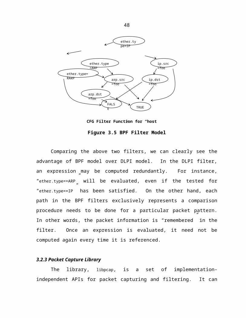
The easiest way to illustrate the algorithm is through an example. Consider the
following matching rules for our ASL packet filtering system.R1: packet(p) | (p.e_type == ETHER_IP) && (p.protocol !=IP_TCP)
&& (p.protocol != IP_UDP) && (p.protocol != IP_ICMP)
&& (p.protocol != IP_IGMP)
R2: packet(p) | (p.e_type == ETHER_IP) && (p.protocol ==IP_UDP)
&& (p.udp_sport == ECHO_PORT) && (p.udp_dport == CHARGEN_PORT)
R3: packet(p) | (p.e_type == ETHER_IP) && (p.protocol ==IP_TCP) && (p.tcp_flag == SYN)
R4: packet(p) | (p.e_type == ETHER_IP) && (p.protocol ==IP_TCP) && (p.tcp_flag == ACK)
We removed the reaction part from each rule intending to focus only on the condition part,
which consists of the packet patterns we need to match. Rule 1 is the exact description of IP
Unknown Protocol attack, where all of the necessary type checking related conditions have
been added. A previously mentioned denial of service intrusion CHARGEN and ECHO is
mapped by rule 2. It is one instance of this intrusion. Other instances can be obtained by
changing the source and destination UDP ports. The third and forth rule consist partly of the
intrusion pattern of SYN flooding, in which, a SYN packet or an ACK packet is matched
separately. The corresponding automaton for above rules is constructed by applying the
procedure Build as shown in Figure 5.6.
As we mentioned earlier, several strategies can be employed in implementing the
function Select, which is used to determine the next offset in a packet to inspect.
{1,2,3,4}
ETHER_IP p.e_type
{1,2,3,4}{}
{3,4}
{3} {4} {}
IP_TCP
{2}
IP_UDP IP_ICMP
p.protocol
IP_IGMP
{}{} {1}SYNACK
p.udp_sport
p.tcp_flag
ECHO_PORT
{} CHARGEN_PORT
p.udp_dport
{} {2}
{1, 2} --1 – candidate rule,2 – matched rule.
{2}
51

Figure 5.6 Sample Automaton for R1-R4
Select an offset such that the number of distinct values appearing at the node is
minimized. With this criterion, we attempt to minimize the number of transitions
out of a state.
Select an offset such that the number of distinct values appearing at the node is
maximized. The motivation here is that the candidate sets associated with each
transition is likely to be smaller.
Select an offset such that the number of rules that involve a test at this offset is
maximized.
Select an offset such that the number of duplicated rules after the current
comparison is minimized. This strategy will reduce the possible redundant
comparisons performed in future.
In the sample automaton, we adopt the third strategy, which tries to involve as many as
possible rules in one offset checking. However, this can be easily changed for an individual
problem.
5.5 Rule Preprocessing
Some preprocessing needs to be done for an ASL rule, before it can be used in
automaton constructing.
5.5.1 Rule Decomposition
Before any two rules can be processed into a single automaton, we need to filter out
each individual comparison expression. Otherwise, we are not able to find the packet offset
checked by more than one rule, or even among different comparison expressions within the
same rule. Take the following two rules as an example:R1: packet(p) | (p.protocol ==IP_TCP) && (p.tcp_flag == SYN)
R2: packet(p) | (p.protocol ==IP_TCP) && (p.tcp_flag == ACK)
52

Every packet offset examined in R1 also appears in R2. And, the conjunction among the
comparison expressions are all “&&”. So, we can decompose the conditions of R1 and R2
into four sub-rules:R11: (p.protocol ==IP_TCP) R12: (p.tcp_flag == SYN)
R21: (p.protocol ==IP_TCP) R22: (p.tcp_flag == ACK)
It is trivial to prove that R1 can be satisfied if and only if both R11 and R12 are satisfied.
Things will become a little bit complicated, if the conjunction “||” is used in the rule.
Nevertheless, we can avoid using “||” in a rule condition by moving “||” out of a rule and
making a single rule become multiple rules at the highest level. So, within a single rule, all
the comparison expression are connected by “&&”.
The following simple recursive algorithm can be employed to turn a single rule into
multiple sub-rules.
Procedure Factor(c) {
1. c is the condition inside a rule to be factored /* in reality, a rule is always
represented by an expression tree */2. if (c is in the form of “c1 && c2”) {
3. Factor(c1); /* recursively call Factor for c1 */
4. Factor(c2); /* recursively call Factor for c2 */
5. } else if (c is in the form of “expr1 operator expr2”) { /* operator can be
‘==’, ‘!=’, etc. */6. create a new sub-rule for the rule being factored
7. }
}
5.5.2 Constraint Stack Construction
After the decomposition step is finished, a rule becomes a collection of comparison
expressions. For expressions involving a packet variable, we need to take care of constraint
checking for each field access.
As we mentioned earlier in this chapter, when a field access within a packet is
accessed, we need to check the type of the variable, such as an ether_hdr or an ip_hdr.
53

This can be done through recursive name lookup in all child structures of the base structure
ether_hdr, as long as each filed name is unique throughout the packet structure hierarchy.
After type checking, we are able to locate the parent structure of the variable and even its
parent’s parent structure through the inheritance relationship among the packet structures.
Following the parent links, we can easily collect all the constraints for the variable and then
build them into a corresponding constraint stack.
An algorithm in pseudo code is used to show the procedure for constraint stack
construction.
Procedure ConsBuild(p, f) {
1. p is a packet variable with correct type information; f is a field
within p
2. s = structof(p); /* structof(p) returns the corresponding structure type for p */
3. for each field f’ of s that appears before f /* iterate in reverse order */4. if f’ has a constraint
5. push the constraint into the stack /* add constraint for the
field in the same structure */6. if s has a constraint
7. push the constraint into the stack /* add constraint for the whole
structure */
8. p’ = parentof(p) /* parentof(p) returns the parent structure type for p; if p is the
base structure, returns null */
9. f’ = lastfieldof(p’) /* lastfieldof(p) returns the last field inside a structure p */10. if (p’ != null)
11. ConsBuild(p’.f’); /* recursively call ConsBuild for p’f’ */}
Applying this algorithm to the expression “p.tcp_flag == SYN”, we can obtain the
constraint stack shown as follows (Figure 5.7).
p.e_type == ETHER_IP
p.protocol == IP_TCP
54

Figure 5.7 Sample Constraint Stack for “p.tcp_flag == SYN”
5.6 Automaton Construction
Up to this point, all the packet-matching rules have been converted into lists of
expression stacks with necessary constraints inside the stack. Next step is to build the
automaton with the algorithm we developed at the Section 5.4.
5.6.1 Offset Selection
In the process of automaton construction, choosing the right variable or offset of a
packet variable to be tested at a comparison step is crucial in reducing the automaton size or
matching time for a packet pattern. The function Select is created for this purpose. In the
implementation of ASL-PFM, we support all the heuristics mentioned in Section 5.4.
One heuristic we always use is to minimize the number of duplicated rules after a
comparison, while preferring fields that lead to creation of small number of branches. The
observation of this heuristic is that it can significantly reduce the size of the created
automaton. A rule will be duplicated into all the branches after a comparison node, if the
variable or offset that is checked in the comparison node is irrelevant to the rule. We then
define the duplicate index of a variable as the product of the number of rules not involved in
examining it and the number of branches of the variable. For instance, we have 5 rules in
total, while 3 of which do not check the variable x and the left 2 rules have the expression
x==1 and x==2 separately. Then we can calculate the duplicate index of x as:DI(x) = 3 * 3 = 9
In the Select function, we compute the duplicate index for each variable and choose the
variable with the minimal value. In case two variables have the same duplicate index, we
will select the one with less number of branches. See the following three rules (we have
omitted the reaction part):R1: (x == 1) && (y == 1)
p.tcp_flag == SYN
55
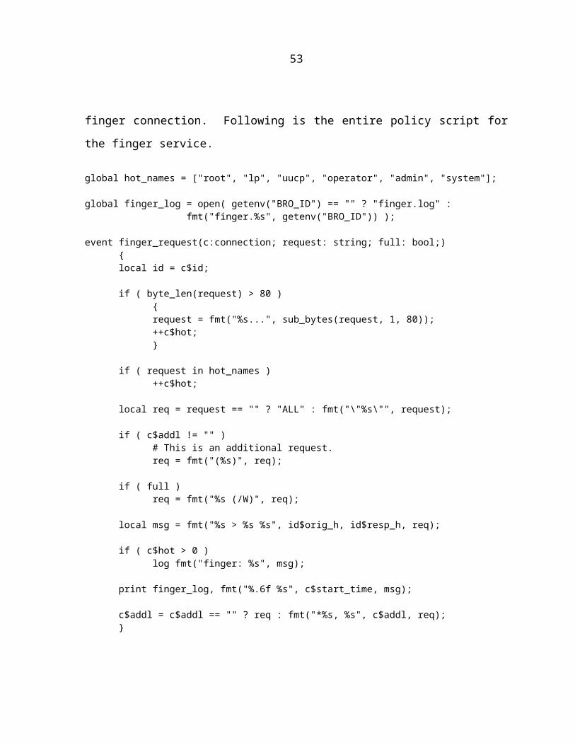
R2: (x == 2) && (y == 1)
R3: (x == 3) && (y == 1)
Both variable x and y have the same duplicate index 0. We can build the automaton in either
way shown in Figure 5.8. However, it is obvious that choosing variable y first can reduce the
size of target automaton.
Choose y first, then x.
Figure 5.8 Sample Automaton
Most operations to a network packet are equality and inequality comparisons, which
can be handled very well by the Select function. For the comparisons like >, >=, <, or <=, we
can consider the whole expression as a single boolean variable with two branches 1 and 0,
representing true and false separately. Then we can apply the Select function in the same
way as to the variable with equality and inequality comparisons. However, there is another
kind of operation with a packet variable, bit-wise operation, especially bit-and. A typical
situation happens when we want to examine the network address of a packet, like in
p.d_addr&0xFFFFFF00 == 0x65432100. In the expression, the hexadecimal value
0xFFFFFF00 is the network mask for an IP address, assuming we are in a class C network.
y y
132
y
x
11 1 1
y
x
1 y
13 1 3
22
x
Choose x first, then y.
56

The bit-and operation brings some difficulty when we apply the Select function. Suppose we
have following two rules: one has an expression p.s_addr == 0x87654321, while the other
one includes an expression p.s_addr&0xFFFFFF00 == 0x87654300.
A solution for this problem is to further decompose the expressions. In the above
case, we can convert the expression p.s_addr == 0x87654321 into two sub-expressions as
follows:
(p.s_addr&oxFFFFFF00==0x87654300)&&(p.s_addr&0x000000FF==0x00000021)
After doing this, we can apply the Select function again and obtain the common offset
s_addr&oxFFFFFF00.
5.6.2 Sub-Automaton Sharing
Under certain circumstance, some redundancy may exist among different sub-
automata in a large automaton. Consider the following automaton built for the two simple
rules listed below (Figure 5.9):R1: packet(p) | p.icmp_type == ECHO_REQ
R2: packet(p) | p.s_addr == 0x87654321
Figure 5.9 Unoptimized Automaton
{1,2}
{1}
{2}
{2}{1,2}
{1,2} {}
{1,2} {} {2}
ETHER_IPp.e_typ
e
IP_ICMP
ECHO_REQ
0x87654321
{1,2} p.s_addr
{2}
0x87654321
p.icmp_type
p.protocol
p.s_addr
p.s_addr
{}
0x87654321
I II
III
57

You may have noticed that the same automaton after the testing for field s_addr
occurred at different place of the automaton. In a larger automaton, this duplication may be
even worse. The reason is that the Build procedure is executed at different node recursively.
Each run is independent and is not aware that the same automaton has been established
somewhere else.
One way to solve this problem is that whenever a procedure needs to create a new
node, let it first looks up all the existing nodes in order to avoid duplicate. However, this
lookup is not trivial. The comparison of the same offset of a packet variable is not strong
enough in deciding whether two nodes are identical. As shown in the Figure 4.9, although
the node I has the same offset compared as that of node II and III, it cannot be substituted by
either node II or III, for it has different matching rule set and candidate rule set. A sufficient
condition for two nodes to be equivalent is both of them have the same comparing variables,
matching rule sets and candidate rule sets. In addition, for a rule in both nodes’ candidate
sets, it must have the same tests remaining for each rule. All of these make the exact input
for our Build procedure and Select function. Therefore, the same input guarantees the node
to be created will be same as well. An optimized version of automaton is shown as follows
(Figure 5.10).
Figure 5.10 Optimized Automaton
{1,2}
{1} {2}
{2}
{1,2}
{1,2} {}
{1,2}
ETHER_IP
p.e_type
IP_ICMP
ECHO_REQ
0x87654321
{1,2} p.s_addr
p.icmp_type
p.protocol
p.s_addr
{}
0x87654321
58
5.7 Code Generation
The ultimate result from our ASL-PFM is an executable code snippet, which can be
used in developing the runtime packet filter.
What a packet filter does is almost the same as an automaton check through an input
stream. A portion of a packet will be compared with some value at a node and the automaton
will then move to the branch with matched value label. When a left node is reached, no
further comparison will be made. Instead, the reaction specified in the rule definition will be
triggered for all matched rules. The code generated by ASL-PFM should exactly reproduce
this process. Take the following two rules as an example, we will see what the generated
code looks like.
Example rules:R1: packet(p) | (p.e_type==0x800) && (p.protocol=1) && (p.icmp_type==8)
message(“ICMP ECHO Request”);
R2: packet(p) | (p.e_type==0x800) && (p.protocol=1) && (p.icmp_type==0)
message(“ICMP ECHO Reply”);
Example Code generated by ASL-PFM:void sample_code(const u_char *p) {
if ((*((unsigned short *)(p+12))) == 8) {
if ((*((unsigned char *)(p+23))) == 1) {
if ((*((unsigned char *)(p+34))) == 8) {
message("ICMP ECHO Request");
}
else if ((*((unsigned char *)(p+34))) == 0) {
message("ICMP ECHO Reply");
}
else {
}
}
else {
}
}
else {
}
59

}
There are a number of issues need to be mentioned around code generation. First of
all, an incoming packet is treated as a byte stream. This is a natural design and can be easily
implemented through various packet capture facilities. The type information of a packet field
is enforced through proper pointer casting as shown in the sample code. One thing needs to
be taken into consideration for a packet field larger than 8 bits is byte order. Normally, we
need to convert the filed in a packet from network order into host order before it can be
compared with any value specified in the rule definition. However, in order to save the
precious time at runtime, we should make the reverse conversion on the predefined values.
In other words, we can change those values from host order into network order at compile
time.
An important issue that may affect the runtime performance of the future packet filter
is the way we handle the comparison and do the branching. In the above sample code, we
simply used if-else statement provided in C. It may work fine for the variable, which has the
number of branches less than 3. In case there are a large number of branches for a variable,
this scheme may greatly degrade the efficiency for a runtime packet filter. An alternative is
binary search, in which the branches of a variable need to be sorted before code generation.
In our implementation, we adopt binary search for each node with the number of branches
more than 3. At runtime, this kind of node can be processed in log2N time, where N is the
number of branches. A further improvement can be achieved by using jump-table or hash-
table if the number of branches become very large.
5.8 Data Generation
Static packet data can be very helpful in the design phase for a real-time packet-
filtering system. It can be used in testing and performance analysis. An ideal data source
should meet the following requirements.
Interpretable by other systems. If the generated data can be fed into other packet-
filtering system, like tcpdump, we can then easily compare our implementation
with others.
60

Easy to specify. On one hand, a user is able to setup every field inside a packet.
On the other hand, data integrity must be guaranteed, i.e. there should be no
conflict among dependent fields and all of the required fields must be filled in
advance automatically. For instance, whenever a UDP packet is specified, the
e_type field of ether_hdr must be set to ETHER_IP as default.
Controllable distribution. When a large amount of data needs to be produced, we
may want a statistically controlled distribution of various packet kinds, like 52%
TCP packets, 23%UDP packets, as well as 25% ICMP and IGMP packets.
The first requirement can be easily achieved with the help of libpcap. After some
modification of libpcap API, we are able to produce packet data file with the compatible
format as the file used by tcpdump.
In terms of field dependence and type checking, the constraint stack concept in our
ASL language design and pointer type casting in the code generation can be a potential
solution. As we have described in Chapter 3, whenever an automaton is constructed, all the
required fields are checked before a packet field is accessed. Therefore, we propose to
convert each reading operation on a packet field into writing a certain value on a pseudo
packet, for the purpose of data generation.
Before various packets can be generated, a user should have a convenient way in
specifying the distribution percentage for each packet kind. We then extend our ASL
language specification intending to provide a weight field for each rule. Following are some
examples:R1: (x == 1) … [0.4]
R2: (x == 2) … [0.6]
R3: (y == 1) … [0.2]
R4: (y == 2) … [0.8]
Because we are focusing on the data generation, both pattern and reaction part have been
omitted from rule definition. The number at the end of each rule is the weight field, which is
the expected percentage for this pattern in the final data generation. There is a little
difference when a rule is specified for the purpose of packet generation, i.e. all the fields
occurring in the rule must be explicitly specified. It means if you have a rule
61
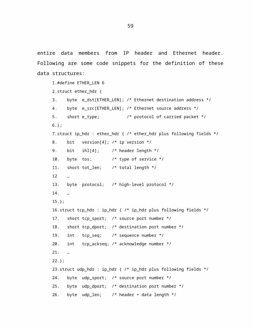
p.s_addr==p.d_addr, you have to change it to (p.s_addr==0x87654321) &&
(p.d_addr==0x87654321). The reason for doing that is to facilitate the packet generation.
In order to achieve the distribution specified in the rule definition, we need to build
the weight into the nodes of the automaton and apply it when the code is generated. The way
we calculate the weight is as follows:
For a left node: the weight is computed by multiplying all the weight specified by
the matched rules. This is simply based on the observation that the possibility of
matching two rules is the product of the possibility of matching each single rule.
For an internal node: the weight is the sum of all the weight of its child nodes.
Figure 5.11 shows the weighted automaton built for the previous example rules.
Figure 5.11 Weighted Automaton
x
y
1
121 2
2
1.0 = 0.4+0.6
z0.4=0.08*0.32 0.6=0.12+0.48
0.48=0.6*0.80.12=0.6*0.20.32=0.4*0.80.08=0.4*0.2
62

CHAPTER 6. EXPERIMENTAL RESULTS AND CONCLUSION
In this thesis, we presented a convenient, expressive and safe language for describing
intrusion patterns and reactions. The primary contribution of this language to a packet filter
construction is independence from the communication protocol and type safety in packet
manipulation operations. We developed an algorithm and implementation for packet filtering
that is based on adaptive pattern matching technique, which is important for improving the
packet filter performance and scalability.
6.1 Intrusion Detection Using ASL
At the end of chapter 4, we once listed some sample intrusion patterns written in
ASL. In the real system, we extended those examples and created a number of new patterns
for the attacks such as Smurf, Land, and so on. More examples can be found in Appendix B./* Smurf (Intermediate Site) */
packet(p) | (p.icmp_type == ICMP_ECHO_TYPE_REQUEST)
&& (p.d_addr == LOCAL_BROADCAST_ADDR)
message(“Smurf”);
/* Land Attack */
packet(p) | (p.s_addr == p.d_addr)
message(“Land attack”);
Our packet filter can fetch a packet either from a tcpdump file or directly from real
network traffic. We also performed testing on some data files generated by our ASL_PFM
itself. This greatly facilitates our testing work, for some attacks are not easy to be simulated
through attacking program or by capturing real network traffic. The final result shows that
our packet filter can efficiently detect (potential) network intrusions.
63

6.2 Preliminary Performance Testing
Performance is a key criterion in evaluating a real-time network packet filter. In this
section, we did some preliminary performance study through a simple utility program, which
is used to collect the number of packets arrived for each network service. We compared our
runtime packet filter and BPF packet filter for this example.
6.2.1 SRVSTAT: Service Statistics
Knowing the number of packets arrived for each network service, e.g. TELNET,
SMTP, or HTTP, can be helpful for the network management purpose, like checking the
traffic load for each machine in the network. In addition, it may also useful in detecting
some malicious network behaviors. For example, if a large number of connection-request
packets are detected at login service port in a short period of time, it is possible that some
hacker is trying to break into your system through password guessing. Following are some
code snippets in the ASL rule definition for SRVSTAT:packet(p) | -> pkt_total ++;
packet(p) | (p.icmp_type == ICMP_ECHO_TYPE_REQUEST)
-> icmp_echo_request ++;
packet(p) | (p.tcp_dport == PORT_HTTP)
-> tcp_http ++;
packet(p) | (p.udp_dport == PORT_NFS)
-> udp_nfs ++;
…
The idea is straightforward. Whenever a packet towards a service is captured, a
corresponding counter for that service will be incremented. In addition, a counter for all the
received packets will be incremented as well, no matter the incoming packet is an ICMP
request or a message to the NFS server. Usually, packet filtering is service specific. This
means a packet filter can be used to collect how many login attempts have been received
from host foo or how many times the finger service is required. In SRVSTAT, we just count
the number of packets received by each service.
An observation from this utility program is that there may be a large number of
patterns for a packet filter, while the number of packet fields covered by these patterns are
64
quite small. For instance, SRVSTAT can have over one hundred patterns specified if we
want to monitor all of normal UNIX network services. However, these patterns may only
access a small number of fields in a packet, such as tcp_dport and udp_dport. In this case,
the processing time of our packet filter will not change too much, because it largely
dependent on the number of packet fields accessed instead of the number of packet patterns.
6.2.2 Performance Comparison: ASL vs. BPF
We also performed some preliminary performance testing on our ASL packet filter
and BPF packet filter. Our focus in this thesis is mainly on the filter model, especially when
the number of packet patterns becomes relatively large. Therefore, we do not consider the
issues, like kernel buffering or kernel filtering, which are implementation techniques that can
be applied to all filter models.
In our test for the filter performance, we compared our runtime ASL filter with BPF
under the conditions, where different numbers of patterns are specified for a filter. To
eliminate the random factors introduced by the live network traffic, we used static tcpdump
files as the data source for both filters.
First, we tested our ASL filter with different branching mechanism used. Figure 6.1
shows that the processing time for our filter, when sequential comparison is used increases
significantly as more patterns are specified for the filter. This is to be expected as the
number of comparison operations introduced by sequential comparison increases linearly
with the number of patterns. Binary search can improve the filter performance. An efficient
hashing function can improve the filter performance even more when the number of branches
are moderate (4 or more).
In the next test, we run both of our ASL filter and BPF over the same set of packets.
Figure 6.2 displays the final results. In terms of absolute performance, BPF is mush slower,
partly because the BPF filter executes interpreter code versus the compiled code in our
approach. In addition, we found that the processing time for our ASL filter does not change
too much as the number of patterns increased.
65

Figure 6.1 Branching Mechanism Comparison for ASL Filter
Figure 6.2 Performance Comparison
6.3 Conclusion
The methods used by network intrusions can be different from one to another.
However, the nature of most network intrusions is based on “malicious” network traffic,
66

which either has invalid value inside a field of a packet, or features incorrect combination or
sequence of packet segments. With this observation, we can use packet-filtering technique in
building network intrusion detection systems.
However, packet filter faces new challenges for the intrusion detection purpose, like
high-volume data, no packet dropping, and requirement for system flexibility and scalability.
In this thesis, we borrowed some idea from the adaptive pattern matching technique and
applied it to our packet-filtering module for a large-scale intrusion detection framework.
One of the key components in our approach is a specification language ASL, which is
used to describe the patterns for the packets to be captured. ASL provides a number of
features in facilitating pattern writing and filter construction, such as packet structure
description and automatic packet type checking.
Building an efficient filter is crucial to the overall system performance. We presented
an elegant algorithm in filter construction. The main concern is how to select a variable or an
offset inside a packet to be inspected at a node of a filter automaton. The primary goal is to
minimize pattern matching time and the size of the automaton.
ASL-PFM provides a novel and elegant way in packet filter design and
implementation for network intrusion detection systems. However, there are still many
topics need to be investigated in the field of packet filtering and network intrusion detection,
such as in kernel integration of packet filtering module.
67

APPENDIX A PACKET DATA STRUCTURES FOR ASL
Ethernet Header:----------------------------------------------------------------------#define ETHER_LEN 6
struct ether_hdr{
byte e_dst[ETHER_LEN];byte e_src[ETHER_LEN];short e_type;
}
ARP:----------------------------------------------------------------------#define ETHER_IP 0x0800#define ETHER_ARP 0x0806
struct arp_hdr : struct ether_hdr with e_type == ETHER_ARP{
short ar_hrd; /* Format of hardware address */short ar_pro; /* Format of protocol address */byte ar_hln; /* Length of hardware address */byte ar_pln; /* Length of protocol address */short ar_op; /* ARP opcode (command). */
}
/* ARP protocol HARDWARE identifiers */#define ARPHRD_ETHER 1 /* Ethernet 10Mbps *//* ARP protocol PROTOCOL identifiers */#define ARPPRO_IP 0x0800 /* IP *//* ARP protocol opcodes */#define ARPOP_REQUEST 1 /* ARP request */#define ARPOP_REPLY 2 /* ARP reply */#define ARPOP_RREQUEST 3 /* RARP request */#define ARPOP_RREPLY 4 /* RARP reply */
struct ether_ip_arp : struct arp_hdr with (ar_hrd == ARPHRD_ETHER) && (ar_pro == ARPPRO_IP)
{byte arp_sha[ETHER_LEN];/* sender hardware address */int arp_spa; /* sender protocol address */byte arp_tha[ETHER_LEN];/* target hardware address */int arp_tpa; /* target protocol address */
}
IP:----------------------------------------------------------------------struct ip_hdr : struct ether_hdr with e_type == ETHER_IP && ihl == 5{
bit version[4]; /* ip version */
68

bit ihl[4]; /* header length */byte tos; /* type of service */short tot_len; /* total length */short id; /* identification */bit flag[3]; /* flags */bit frag_off[13]; /* fragment offset */byte ttl; /* time to live */byte protocol; /* protocol */short check_sum; /* header checksum */ip_addr s_addr; /* source ip address */ip_addr d_addr; /* destination address */
}
struct ip_pkt : struct ip_hdr{
byte ip_data[tot_len - ihl];}
ICMP:----------------------------------------------------------------------/* IP protocol PROTOCOL identifiers. */#define IP_ICMP 0x0001 /* ICMP */#define IP_IGMP 0x0002 /* IGMP */#define IP_TCP 0x0006 /* TCP */#define IP_UDP 0x0011 /* UDP */
struct icmp_hdr : struct ip_hdr with protocol == IP_ICMP{
byte icmp_type; /* icmp message type */byte icmp_code; /* icmp message code */short icmp_csum; /* checksum for entire message */
}
struct icmp_pkt : struct icmp_hdr{
byte icmp_data[tot_len - ihl - sizeof(icmp_hdr)];}
#define ICMP_ECHO_TYPE_REQUEST 8#define ICMP_ECHO_TYPE_REPLY 0#define ICMP_ECHO_CODE 0
struct icmp_echo_request : struct icmp_hdr with(icmp_type == ICMP_ECHO_TYPE_REQUEST)&& (icmp_code == ICMP_ECHO_CODE)
{byte icmp_echoid; /* identifier */byte icmp_echoseq; /* sequence number */byte icmp_echodata[tot_len - ihl - sizeof(icmp_hdr) - 2];
}
struct icmp_echo_reply : struct icmp_hdr with(icmp_type == ICMP_ECHO_TYPE_REPLY) && (icm_code == ICMP_ECHO_CODE)
{
69

byte icmp_echoid; /* identifier */byte icmp_echoseq; /* sequence number */byte icmp_echodata[tot_len - ihl - sizeof(icmp_hdr) - 2];
}
#define ICMP_DESUNREA_TYPE 3struct icmp_unreach : struct icmp_hdr with
icmp_type == ICMP_DESUNREA_TYPE{
short icmp_reserved;ip_hdr icmp_iphdr;byte icmp_data[8];
}
#define ICMP_SRCQUEN_TYPE 4#define ICMP_SRCQUEN_CODE 0struct icmp_squench : struct icmp_hdr with
icmp_type == ICMP_SRCQUEN_TYPE{
short icmp_reserved;ip_hdr icmp_iphdr;byte icmp_data[8];
}
UDP:----------------------------------------------------------------------struct udp_hdr : struct ip_hdr with protocol == IP_UDP{
byte udp_sport; /* source port number */byte udp_dport; /* destination port number */byte udp_len; /* header + data length */byte udp_csum; /* checksum for header & data */
}
struct udp_pkt : struct udp_hdr{
byte udp_data[udp_len - sizeof(udp_hdr)];/* data */}
TCP:----------------------------------------------------------------------struct tcp_hdr : struct ip_hdr with protocol == IP_TCP{
short tcp_sport; /* source port number */short tcp_dport; /* destination port number */int tcp_seq; /* sequence number */int tcp_ack; /* acknowledge number */bit tcp_hlen[4]; /* header length */bit tcp_reserved[6]; /* reserved */bit tcp_urg; /* flags */bit tcp_ack;bit tcp_psh;bit tcp_rst;
70
bit tcp_syn;bit tcp_fin;short tcp_win; /* window size */short tcp_csum; /* checksum for header & data */short tcp_urp; /* urgent pointer */
}
struct tcp_pkt : struct tcp_hdr{
byte tcp_data[tot_len - ihl - tcphlen];}
DNS:----------------------------------------------------------------------#define DNS_PORT 53
struct dns_hdr : struct udp_hdr with(udp_sport == DNS_PORT) || (udp_dport == DNS_PORT)/* either to a dns port or from dns port */
{short dns_id; /* identifier */short dns_flags; /* flags */short dns_nques; /* No. of questions */short dns_nans; /* No. of answers RR */short dns_nauth; /* No. of authority RRs */short dns_nadd; /* No. of additional RRs */
}
struct dns_ques{
string dns_qname; /* query name */short dns_qtype; /* query type */short dns_qclass; /* query class */
}
struct dns_rr_hdr{
string dname; /* domain name */short type; /* RR type */short class; /* RR class */int ttl; /* time to live */
}
#define DNS_QUERY_A 1struct dns_rr_A : struct dns_rr_hdr rrhdr with rrhdr.type == DNS_QUERY_A{
short rdlen; /* resource data length */ip_addr rdata[rdlen];
}
struct dns_pkt_A : struct dns_hdr dnshdr{
struct dns_ques dques[nques]; /* dns questions */struct dns_rr_A dans[nans]; /* dns answer RRs */
71

struct dns_rr_A dauth[nauth]; /* dns authority RRs */struct dns_rr_A dadd[nadd]; /* dns additional RRs */
}
RIP:----------------------------------------------------------------------#define RIP_PORT 520
struct rip_hdr : struct udp_hdr with(udp_sport == RIP_PORT) || (udp_dport == RIP_PORT)/* either to a rip port or from rip port */
{byte rip_command; /* rip command */byte rip_version; /* rip version */short rip_zero; /* must be zero */
}
struct rip_rec{
short rip_afid; /* address family identifier */short rip_zero; /* must be zero */int rip_ipaddr; /* ip address */int rip_zero[2]; /* must be zero */int rip_metric; /* metric */
}
strcut rip_pkt : struct rip_hdr{
rip_rec riprec[(udp_len - sizeof(struct rip_hdr))/ sizeof(struct rip_rec)];
}
72

APPENDIX B INTRUSION PATTERN SAMPLES
1. IP Unknown ProtocolModule IPUnknownProtocol() {
packet(p)|(p.protocol != IP_TCP) && (p.protocol != IP_UDP)
&& (p.protocol != IP_ICMP) && (p.protocol != IP_IGMP)
message(“IP Unknown Protocol”);
}
2. Ping of DeathModule PingofDeath() {
packet(p)|(p.tot_len + p.frag_off > MAX_IP_SIZE)
message(“Ping of Death”);
}
3. Chargen, Echo, Time, DaytimeModule CETD(sPort, dPort) {
packet(p)|(p.udp_sport == sPort) && (p.udp_dport == dPort)
message(“CETD Attack”);
}
4. Finger Buffer Overflow#define FINGERD_PORT 79
Module FingerOverflow() {
packet(p)|(p.tcp_dport == FINGERD_PORT)
&& (p.tot_len – p.ihl – p.tcp_hlen) > MAX_FINGER_LEN)
message(“Finger Buffer Overflow”);
}
5. LAND AttackModule LAND() {
packet(p)|(p.s_addr == p.d_addr) message(“LAND Attack”);
}
6. Smurf (Intermediate Site)
73

Module Smurf() {
packet(p)|(p.icmp_type == ICMP_ECHO_TYPE_REQUEST)
&& (p.d_addr == LOCAL_NET_BROADCAST_ADDR)
message(“Smurf Attack”);
}
7. IP Spoofing/* for external interface */
Module IPSExternal() {
packet(p)|(p.s_addr&INSIDE_NET_MASK == INSIDE_NET_ADDR)
message(“IPS External”);
}
/* for internal interface */
Module IPSInternal() {
packet(p)|(p.s_addr&INSIDE_NET_MASK != INSIDE_NET_ADDR)
message(“IPS Internal”);
}
8. SYN FloodingModule SYNFlooding() {
packet(p)|(p.tcp_flag == SYN)
nSyn = nSyn + 1;
every predefined interval, check
if (nSyn > SYN_THRESHOLD)
message(“SYN Flooding”);
else
nSyn = 0;
packet(p)|(p.tcp_flag == ACK)
if (nSyn > 0)
nSyn = nSyn – 1;
}
9. Ping Flooding
74

Module PingFlooding() {
packet(p)|(p.icmp_type == ICMP_ECHO_TYPE_REQUEST)
nPing = nPing + 1;
every predefined interval, check
if (nPing > PING_THRESHOLD)
message(“Ping Flooding”);
else
nPing = 0;
}
10. RIP Trace#define 3
Module RIPTrace() {
packet(p)|(p.rip_command == RIP_TRACE_COMMAND)
message(“RIP Trace Command On”);
}
75

REFERENCES
[1] Larry J. Hughes, Jr. Actually Useful Internet Security Techniques, New Riders
Publishing, Indianapolis, IN, 1995.
[2] R. Heady, G. Luger, A. Maccabe, and B. Mukherjee. A Method To Detect Intrusive
Activity in a Networked Environment. In Proceedings of the 14th National Computer
Security Conference, pages 362-371, October 1991.
[3] Abdelaziz Monnji. Languages and Tools for Rule-Based Distributed Intrusion
Detection, PhD thesis, Facultes Universitaires, Notre-Dame de la Paix, Belgium,
September 1997.
[4] W. R. Stevens. TCP/IP Illustrated Vol. 1 – The Protocols, Addison-Wesley
Publishing Company, Inc. Reading, MA, 1994.
[5] S. M. Bellovin. Security Problems in the TCP/IP Protocol Suite, Computer
Communications Review, Vol. 19, No. 2, pp. 32-48, April 1989.
[6] Morris R. A Weakness in the 4.2 BSD UNIX TCP/IP Software, Computer Science
Technical Report No 117, AT&T Bell Laboratories, Murray Hill, NJ, 1985.
[7] CERT. TCP SYN Flooding and IP Spoofing Attacks, Carnegie Mellon University,
Pittsburgh, PA, September 1996.
[8] C. Cobb and S. Cobb. Denial of Service, Secure Computing, pp.58-60, July 1997.
[9] C. L. Schuba, I.V. Krsul, Makus G. Kuhn, E.H. Spafford, A. Sundaram, D. Zamboni.
Analysis of a Denial of Service Attack on TCP, Purdue University, West Lafayette,
IN, 1996.
[10] S. Dash. Integration of DNSSEC (key-server) with Ssh Application, MS thesis, Iowa
State University, Ames, IA, 1997.
[11] W. R. Stevens. UNIX Network Programming Vol. 1 – Network APIs: Sockets and
XTI, Second Edition, Prentice Hall PTR, Upper Saddle River, NJ, 1998.
[12] Vern Paxson. Bro: A System for Detecting Network Intruders in Real-Time,
Lawrence Berkeley National Laboratory, Berkeley, CA, 1998.
76

[13] R. C. Sekar, R. Ramesh, I. V. Ramakrishnan. Adaptive Pattern Matching, Bellcore,
Morristown, NJ, 1993.
[14] Steven McCanne, Van Jacobson. The BSD Packet Filter: A New Architecture for
User-level Packet Capture, Lawrence Berkeley Laboratory, Berkeley, CA, 1992.
[15] Biswanath Mukherjee, L. Todd Heberlein, Karl N. Levitt. Network Intrusion
Detection, IEEE Network, pp.26-41, May/June 1994.
[16] Frederick B. Cohen. A Node on Distributed Coordinated Attacks, Computer &
Security, pp.103-121, v15, 1996.
[17] Steven Cheung, Karl N. Levitt. Protecting Routing Infrastructures from Denial of
Service Using Cooperative Intrusion Detection, University of California, Davis, CA,
1997.
[18] Christoph L. Schuba. Addressing Weakness in the Domain Name System Protocol,
COAST Laboratory, Purdue University, West Lafayette, IN, 1993.
[19] Eugene H. Spafford. The Internet Worm Incident, Technical Report CSD-TR-993,
Purdue University, West Lafayette, IN, September 19, 1991.
77

ACKNOWLEDGEMENTS
I wish to express my sincere appreciation to Dr. R. C. Sekar, my major professor, for
his full support, valuable advice and assistance to carry out and complete this research.
I would like to thank Dr. Johnny Wong for his help in my graduate study. His
encouragement and support makes my two years study at Iowa State University the most
rewarding time in my life.
The contribution of Dr. Doug Jacobson as committee member is greatly
acknowledged.
Many thanks to Premchand Uppuluri, Ravi Vankamamidi and Yong Cai for their help
to my research and study.
Finally, thanks for the love from my parents and my wife, Li Fang. Without their
support, I would not have completed this research.
This project is supported by Defense Advanced Research Project Agency's
Information Technology Office (DARPA-ITO) under the Information System Survivability
program, under contract number F30602-97-C-0244.
78


![H2E: A Privacy Provisioning Framework for Collaborative Filtering … · 2019-09-10 · collaborative filtering, content-based filtering, and hybrid filtering [3]. Content-based filtering,](https://static.fdocuments.us/doc/165x107/5f2811153d39b70bb31af3b8/h2e-a-privacy-provisioning-framework-for-collaborative-filtering-2019-09-10-collaborative.jpg)