
3366-738
52
Form No. 3366-738 Rev A Groundsmaster ® 4500-D or 4700-D Traction Unit Model No. 30857—Serial No. 310000501 and Up Model No. 30858—Serial No. 310000501 and Up To register your product or download an Operator's Manual or Parts Catalog at no charge, go to www.Toro.com. Original Instructions (EN)
-
Upload
negimachi-negimachi -
Category
Documents
-
view
213 -
download
1
description
FormNo. 3366-738RevA ModelNo.30857—SerialNo.310000501andUp ModelNo.30858—SerialNo.310000501andUp ToregisteryourproductordownloadanOperator'sManualorPartsCatalogatnocharge,gotowww.Toro.com. OriginalInstructions(EN)
Transcript of 3366-738

Form No. 3366-738 Rev A
Groundsmaster® 4500-D or4700-D Traction UnitModel No. 30857—Serial No. 310000501 and Up
Model No. 30858—Serial No. 310000501 and Up
To register your product or download an Operator's Manual or Parts Catalog at no charge, go to www.Toro.com. Original Instructions (EN)

This product complies with all relevant Europeandirectives, for details please see the separate productspecific Declaration of Conformity (DOC) sheet.
WARNINGCALIFORNIA
Proposition 65 WarningDiesel engine exhaust and some of itsconstituents are known to the State ofCalifornia to cause cancer, birth defects,
and other reproductive harm.
Because in some areas there are local, state, or federalregulations requiring that a spark arrester be used on theengine of this machine, a spark arrester is incorporatedwith the muffler assembly.
Genuine Toro spark arresters are approved by the USDAForestry Service.
Important: This engine is equipped with a sparkarrester muffler. It is a violation of California PublicResource Code Section 4442 to use or operatethe engine on any forest-covered, brush-covered,or grass-covered land without a spark arrestermuffler maintained in working order, or the engineconstricted, equipped, and maintained for theprevention of fire. Other states or federal areas mayhave similar laws.
This spark ignition system complies with CanadianICES-002.
The enclosed Engine Owner’s Manual is suppliedfor information regarding the US EnvironmentalProtection Agency (EPA) and the CaliforniaEmission Control Regulation of emission systems,maintenance, and warranty. Replacements may beordered through the engine manufacturer.
IntroductionThis machine is a ride-on, rotary-blade lawnmowerintended to be used by professional, hired operators incommercial applications. It is primarily designed forcutting grass on well-maintained lawns in parks, golfcourses, sports fields, and on commercial grounds. It isnot designed for cutting brush, mowing grass and othergrowth alongside highways, or for agricultural uses.
Read this information carefully to learn how to operateand maintain your product properly and to avoid injuryand product damage. You are responsible for operatingthe product properly and safely.
You may contact Toro directly at www.Toro.com forproduct and accessory information, help finding adealer, or to register your product.
Whenever you need service, genuine Toro parts, oradditional information, contact an Authorized ServiceDealer or Toro Customer Service and have the modeland serial numbers of your product ready. Figure 1identifies the location of the model and serial numberson the right front frame member of the product. Writethe numbers in the space provided.
Figure 11. Model and serial number location
Model No.
Serial No.
This manual identifies potential hazards and hassafety messages identified by the safety alert symbol(Figure 2), which signals a hazard that may cause seriousinjury or death if you do not follow the recommendedprecautions.
Figure 21. Safety alert symbol.
This manual uses two other words to highlightinformation. Important calls attention to specialmechanical information and Note emphasizes generalinformation worthy of special attention.
© 2010—The Toro® Company8111 Lyndale Avenue SouthBloomington, MN 55420 2
Contact us at www.Toro.com.Printed in the USA.All Rights Reserved

ContentsIntroduction................................................................. 2Safety ........................................................................... 4
Safe Operating Practices ....................................... 4Toro Riding Mower Safety .................................... 6Sound Power Level............................................... 7Sound Pressure Level ........................................... 7Vibration Level .................................................... 7Safety and Instructional Decals ............................. 8
Setup.......................................................................... 121 Replacing the Warning Decal for CECompliance .................................................... 13
2 Installing the Hood Lock for CECompliance .................................................... 13
3 Installing the Throttle Stop for CECompliance when Installing Optional HighLift Blades...................................................... 13
4 Greasing the Machine ...................................... 145 Checking Fluid Levels ...................................... 14
Product Overview ...................................................... 15Controls ............................................................. 15Specifications ..................................................... 18Traction Unit Specifications................................ 18Attachments/Accessories................................... 18
Operation................................................................... 19Checking the Engine Oil Level............................ 19Checking the Cooling System.............................. 19Filling the Fuel Tank........................................... 20Checking theHydraulic Fluid Level..................... 21Checking the Tire Pressure ................................. 22Starting and Stopping the Engine ........................ 22Checking the Interlock Switches ......................... 23Pushing or Towing theMachine .......................... 23Jacking Points..................................................... 24Tie Downs ......................................................... 24Operating Characteristics ................................... 24Engine Cooling FanOperation ........................... 24Operating Tips ................................................... 25
Maintenance............................................................... 26RecommendedMaintenance Schedule(s) ................ 26Daily Maintenance Checklist............................... 27Service Interval Chart......................................... 28
Premaintenance Procedures.................................... 29Removing the Hood ........................................... 29
Lubrication............................................................. 29Greasing the Bearings and Bushings.................... 29
Engine Maintenance............................................... 31Servicing the Air Cleaner .................................... 31Servicing the EngineOil and Filter...................... 32Adjusting the Throttle ........................................ 33
Fuel SystemMaintenance ....................................... 33Fuel Tank ........................................................... 33
Fuel Lines and Connections................................ 33Servicing theWater Separator ............................. 33Fuel Pick up Tube Screen.................................... 34Bleeding Air from the Injectors........................... 34
Electrical SystemMaintenance................................ 35Charging and Connecting the Battery .................. 35Battery Care ....................................................... 36Fuses.................................................................. 36
Drive SystemMaintenance ..................................... 37Checking the Torque of the WheelNuts............................................................... 37
Checking the Planetary Gear DriveOil.................................................................. 37
Changing the Planetary Gear DriveOil.................................................................. 38
Checking the Rear Axle Lubricant ....................... 38Changing the Rear Axle Lubricant....................... 39Adjusting the TractionDrive forNeutral ............. 39Checking the RearWheel Toe-In......................... 39
Cooling SystemMaintenance .................................. 40Servicing the Engine Cooling System .................. 40
Brake Maintenance ................................................. 41Adjusting the Service Brakes............................... 41
Belt Maintenance.................................................... 42Servicing the Alternator Belt............................... 42
Hydraulic SystemMaintenance ............................... 42Changing the Hydraulic Fluid ............................. 42Replacing the Hydraulic Filters ........................... 42Checking theHydraulic Lines andHoses ............. 43Changing the Counterbalance Settings ................ 43
Cleaning ................................................................. 45Servicing the Spark ArrestorMuffler................... 45
Storage ....................................................................... 45Traction Unit...................................................... 45Engine ............................................................... 45
Schematics ................................................................. 46
3

SafetyThis machine meets or exceeds CEN standard EN836:1997 (when appropriate decals applied), and ANSIB71.4-2004 specifications in effect at the time ofproduction.
Improper use or maintenance by the operator orowner can result in injury. To reduce the potentialfor injury, comply with these safety instructionsand always pay attention to the safety alert symbol,which means CAUTION, WARNING, or DANGER-"personal safety instruction." Failure to comply with theinstruction may result in personal injury or death.
Safe Operating PracticesThe following instructions are from the CEN standardEN 836:1997, ISO standard 5395:1990, and ANSIB71.4-2004.
Training• Read the operator’s manual and other training
material carefully. Be familiar with the controls,safety signs, and the proper use of the equipment.
• If the operator or mechanic can not read the languageof this manual, it is the owner’s responsibility toexplain this material to them.
• Never allow children or people unfamiliar with theseinstructions to use or service the mower. Localregulations may restrict the age of the operator.
• Never mow while people, especially children, or petsare nearby.
• Keep in mind that the operator or user is responsiblefor accidents or hazards occurring to other people ortheir property.
• Do not carry passengers.• All drivers and mechanics should seek and obtain
professional and practical instruction. The owner isresponsible for training the users. Such instructionshould emphasize:– the need for care and concentration when
working with ride-on machines;– control of a ride-on machine sliding on a slope
will not be regained by the application of thebrake. The main reasons for loss of control are:◊ insufficient wheel grip;◊ being driven too fast;◊ inadequate braking;◊ the type of machine is unsuitable for the task;
◊ lack of awareness of the effect of groundconditions, especially slopes;
• The owner/user can prevent and is responsible foraccidents or injuries occurring to himself or herself,other people, or property.
Preparation• While mowing, always wear substantial footwear,
long trousers, hard hat, safety glasses, and hearingprotection. Long hair, loose clothing, or jewelry mayget tangled in moving parts. Do not operate theequipment when barefoot or wearing open sandals.
• Thoroughly inspect the area where the equipmentis to be used and remove all objects which may bethrown by the machine.
• Warning-Fuel is highly flammable. Take thefollowing precautions:– Store fuel in containers specifically designed for
this purpose.– Refuel outdoors only and do not smoke while
refueling.– Add fuel before starting the engine. Never
remove the cap of the fuel tank or add fuel whilethe engine is running or when the engine is hot.
– If fuel is spilled, do not attempt to start theengine but move the machine away from thearea of spillage and avoid creating any source ofignition until fuel vapors have dissipated.
– Replace all fuel tank and container caps securely.• Replace faulty silencers/mufflers.• Evaluate the terrain to determine what accessories
and attachments are needed to properly andsafely perform the job. Only use accessories andattachments approved by the manufacturer.
• Check that operator’s presence controls, safetyswitches and shields are attached and functioningproperly. Do not operate unless they are functioningproperly.
Operation• Do not operate the engine in a confined space where
dangerous carbon monoxide fumes can collect.• Mow only in daylight or in good artificial light.• Before attempting to start the engine, disengage all
blade attachment clutches, shift into neutral, andengage the parking brake.
• Do not put hands or feet near or under rotating parts.Keep clear of the discharge opening at all times.
4

• Remember there is no such thing as a safe slope.Travel on grass slopes requires particular care. Toguard against overturning:– do not stop or start suddenly when going up or
downhill;– machine speeds should be kept low on slopes
and during tight turns;– stay alert for humps and hollows and other
hidden hazards;– never mow across the face of the slope, unless
the mower is designed for this purpose.– Use counterweight(s) or wheel weights when
suggested in the operator’s manual.• Stay alert for holes in the terrain and other hidden
hazards.• Watch out for traffic when crossing or near roadways.• Stop the blades from rotating before crossing
surfaces other than grass.• Never operate the machine with damaged guards,
shields, or without safety protective devices in place.Be sure all interlocks are attached, adjusted properly,and functioning properly.
• Do not change the engine governor settings oroverspeed the engine. Operating the engine atexcessive speed may increase the hazard of personalinjury.
• Before leaving the operator’s position:– stop on level ground;– disengage the power take-off and lower the
attachments;– set the parking brake;– stop the engine and remove the key.
Important: Allow engine to idle for 5minutes before shutting it off after a fullload operation. Failure to do so may lead toturbo-charger trouble.
• Stop the engine– before refuelling;– before making height adjustment .– before clearing blockages;– before checking, cleaning or working on the
mower;– after striking a foreign object or if an abnormal
vibration occurs. Inspect the mower for damageand make repairs before restarting and operatingthe equipment.
• Reduce the throttle setting during engine run-out.
• Keep hands and feet away from the cutting units.• Look behind and down before backing up to be sure
of a clear path.• Slow down and use caution when making turns and
crossing roads and sidewalks. Stop blades fromrotating.
• Be aware of the mower discharge direction and donot point it at anyone.
• Do not operate the mower under the influence ofalcohol or drugs
• Lightning can cause severe injury or death. Iflightning is seen or thunder is heard in the area, donot operate the machine; seek shelter.
• Use care when loading or unloading the machineinto a trailer or truck
• Use care when approaching blind corners, shrubs,trees, or other objects that may obscure vision.
Maintenance and Storage• Keep all nuts, bolts and screws tight to be sure the
equipment is in safe working condition.• Never store the equipment with fuel in the tank
inside a building where fumes may reach an openflame or spark.
• Allow the engine to cool before storing in anyenclosure.
• To reduce the fire hazard, keep the engine,silencer/muffler, battery compartment and fuelstorage area free of grass, leaves, or excessive grease.
• Keep all parts in good working condition and allhardware and hydraulic fittings tightened. Replace allworn or damaged parts and decals.
• If the fuel tank has to be drained, do this outdoors.• Be careful during adjustment of the machine to
prevent entrapment of the fingers between movingblades and fixed parts of the machine.
• On multi-spindle mowers, take care as rotating oneblade can cause other blades to rotate.
• Disengage drives, lower the cutting units, set parkingbrake, stop engine and remove ignition key. Wait forall movement to stop before adjusting, cleaning orrepairing.
• Clean grass and debris from cutting units, drives,silencers/mufflers, and engine to help prevent fires.Clean up oil or fuel spillage.
• Use jack stands to support components whenrequired.
• Carefully release pressure from components withstored energy.
5

• Disconnect battery before making any repairs.Disconnect the negative terminal first and thepositive last. Reconnect positive first and negativelast.
• Use care when checking the blades. Wear gloves anduse caution when servicing them.
• Keep hands and feet away from moving parts. Ifpossible, do not make adjustments with the enginerunning.
• Charge batteries in an open well ventilated area,away from spark and flames. Unplug charger beforeconnecting or disconnecting from battery. Wearprotective clothing and use insulated tools.
• Store the machine with the cutting units in thelowered position or secure the wing decks with thestorage latches to prevent them from unintentionallylowering.
Toro Riding Mower SafetyThe following list contains safety information specificto Toro products or other safety information that youmust know that is not included in the CEN, ISO, orANSI standard.
This product is capable of amputating hands andfeet and throwing objects. Always follow all safetyinstructions to avoid serious injury or death.
Use of this product for purposes other than its intendeduse could prove dangerous to user and bystanders.
WARNINGEngine exhaust contains carbon monoxide, whichis an odorless, deadly poison that can kill you.
Do not run engine indoors or in an enclosed area.
• Know how to stop the engine quickly.• Do not operate the machine while wearing tennis
shoes or sneakers.• Wearing safety shoes and long pants is advisable and
required by some local ordinances and insuranceregulations.
• Handle fuel carefully. Wipe up any spills.• Check the safety interlock switches daily for proper
operation. If a switch should fail, replace the switchbefore operating the machine.
• Before starting the engine, sit on the seat.• Using the machine demands attention. To prevent
loss of control:– Do not drive close to sand traps, ditches, creeks,
embankments, or other hazards.
– Reduce speed when making sharp turns. Avoidsudden stops and starts.
– When near or crossing roads, always yield theright-of-way.
– Apply the service brakes when going downhill tokeep forward speed slow and to maintain controlof the machine.
• When operating a machine with ROPS (roll-overprotection system) never remove the ROPS andalways use the seat belt.
• Raise the cutting units when driving from one workarea to another.
• Do not touch the engine, silencer/muffler, orexhaust pipe while the engine is running or soonafter it has stopped because these areas could be hotenough to cause burns.
• On any hill, there is the possibility of tipping orrolling over, but the risk increases as the slope angleincreases. Steep hills should be avoided.
Cutting units must be lowered when going downslopes to maintain steering control
• Engage traction drive slowly, always keep foot ontraction pedal, especially when traveling downhill.
Use reverse on traction pedal for braking.• If the machine stalls when climbing a slope, do
not turn the machine around. Always back slowly,straight down the slope.
• When a person or pet appears unexpectedly inor near the mowing area, stop mowing. Carelessoperation, combined with terrain angles, ricochets,or improperly positioned guards can lead to thrownobject injuries. Do not resume mowing until thearea is cleared.
Maintenance and Storage• Make sure all hydraulic line connectors are tight and
all hydraulic hoses and lines are in good conditionbefore applying pressure to the system.
• Keep your body and hands away from pin holeleaks or nozzles that eject hydraulic fluid underhigh pressure. Use paper or cardboard, not yourhands, to search for leaks. Hydraulic fluid escapingunder pressure can have sufficient force to penetratethe skin and cause serious injury. Seek immediatemedical attention if fluid is injected into skin.
• Before disconnecting or performing any work onthe hydraulic system, all pressure in the system mustbe relieved by stopping the engine and lowering thecutting units and attachments to the ground.
6

• Check all fuel lines for tightness and wear on aregular basis. Tighten or repair them as needed.
• If the engine must be running to perform amaintenance adjustment, keep hands, feet, clothing,and any parts of the body away from the cuttingunits, attachments, and any moving parts.
• To ensure safety and accuracy, have an AuthorizedToro Distributor check the maximum engine speedwith a tachometer.
• If major repairs are ever needed or if assistance isdesired, contact an Authorized Toro Distributor.
• Use only Toro-approved attachments andreplacement parts. The warranty may be voided ifused with unapproved attachments.
Sound Power LevelThis unit has a guaranteed sound power level of 105dBA, which includes an Uncertainty Value (K) of 1 dBA.
Sound power level was determined according to theprocedures outlined in ISO 11094.
Sound Pressure LevelThis unit has a sound pressure level at the operator’sear of 90 dBA, which includes an Uncertainty Value (K)of 1 dBA.
Sound pressure level was determined according to theprocedures outlined in EN 836.
Vibration LevelGroundsmaster 4500
Hand-Arm
Measured vibration level for right hand = .57 m/s2
Measured vibration level for left hand =1.02 m/s2
Uncertainty Value (K) = 0.5 m/s2
Measured values were determined according to theprocedures outlined in EN 836.
Whole Body
Measured vibration level = .49 m/s2
Uncertainty Value (K) = 0.5 m/s2
Measured values were determined according to theprocedures outlined in EN 836.
Groundsmaster 4700
Hand-Arm
Measured vibration level for right hand = 1.21 m/s2
Measured vibration level for left hand =1.25 m/s2
Uncertainty Value (K) = 0.5 m/s2
Measured values were determined according to theprocedures outlined in EN 836.
Whole Body
Measured vibration level = .46 m/s2
Uncertainty Value (K) = 0.5 m/s2
Measured values were determined according to theprocedures outlined in EN 836.
7

Safety and Instructional Decals
Safety decals and instructions are easily visible to the operator and are located near any area ofpotential danger. Replace any decal that is damaged or lost.
117-47631. To engage the parking
brake, secure the brakepedals with the locking pin,press the parking brakepedals and engage the toepedal.
2. To disengage the parkingbrake, disengage thelocking pin and releasethe pedals.
117–23841. Off 6. Power Take-off (PTO)2. Headlights 7. High3. On 8. Traction control4. Fast 9. Low5. Slow
117–23851. Read the Operators
Manual.3. Engine—preheat
2. Engine—start 4. Engine—stop
117–23871. Raise left deck 4. Cooling fan2. Raise center deck 5. Reverse3. Raise right deck 6. Automatic
117-47651. Read the Operator’s Manual.2. Do not use starting aids.
8

117-47661. Cutting/dismemberment hazard; fan—stay away from
moving parts.
106-67551. Engine coolant under
pressure.3. Warning—do not touch
the hot surface.2. Explosion hazard—read
the Operator’s Manual.4. Warning—read the
Operator’s Manual.
117-47641. Thrown object hazard—keep bystanders a safe distance
from the machine.2. Cutting hazard of hand, mower blade—stay away from
moving parts, keep all guards and shields in place.3. Cutting hazard of foot, mower blade—stay away from
moving parts, keep all guards and shields in place.
98-43871. Warning—wear hearing protection.
106-67541. Warning—do not touch the hot surface.2. Cutting/dismemberment hazard, fan and entanglement
hazard, belt—stay away from moving parts.
112-52971. Warning—read the Operator’s Manual, do not operate this
machine unless you are trained.2. Warning—read the Operator’s Manual before towing the
machine.3. Tipping hazard—slow machine before turning, do not turn
at high speeds; lower the cutting unit when driving downslopes; use a roll over protection system and wear the seatbelt
4. Warning—do not park the machine on slopes; engage theparking brake, lower the cutting units, stop the engine andremove the ignition key before leaving the machine.
5. Thrown object hazard—keep bystanders a safe distancefrom the machine.
6. Entanglement hazard, belt—stay away from moving parts,keep all guards and shields in place.
9

112-5298(Affix over part no. 112–5297 for CE*
* This safety decal includes a slope warning required on the machinefor compliance to the European Lawn Mower Safety Standard EN836:1997. Theconservative maximum slope angles indicated for operation of this machine are
prescribed by and required by this standard.
1. Warning—read the Operator’s Manual, do not operate thismachine unless you are trained.
2. Warning—read the Operator’s Manual before towing themachine.
3. Tipping hazard—do not operate on slopes greater than 15°;lower the cutting units when operating on slopes; wear thesafety belt.
4. Warning—do not park the machine on slopes; engage theparking brake, lower the cutting units, stop the engine andremove the ignition key before leaving the machine.
5. Thrown object hazard—keep bystanders a safe distancefrom the machine.
6. Entanglement hazard, belt—stay away from moving parts,keep all guards and shields in place.
117-47611. Starter, 20A 6. GM4500 controller, 2A2. Work light, 10A 7. Power supplied, 7.5A3. Seat, 10A 8. GM4700 controller, 2A4. Power point, 10A 9. Engine preheat, 60A5. Gauges, 10A
Battery SymbolsSome or all of these symbols are on your battery
1. Explosion hazard 6. Keep bystandersa safedistance from the battery.
2. No fire, open flame, orsmoking.
7. Wear eye protection;explosive gases cancause blindness and otherinjuries
3. Caustic liquid/chemicalburn hazard
8. Battery acid can causeblindness or severe burns.
4. Wear eye protection 9. Flush eyes immediatelywith water and get medicalhelp fast.
5. Read the Operator’sManual.
10. Contains lead; do notdiscard.
93-7272(Models 30630 & 30631)
1. Cutting/dismemberment hazard; fan—stay away fro movingparts.
117–2718
10

117-4758
11

SetupLoose PartsUse the chart below to verify that all parts have been shipped.
Procedure Description Qty. Use
1 Warning decal 1 Used only on machines requiringEuropean CE Compliance.
Hood lock bracket 1Rivets 2Screw (1/4 x 1–1/2 inch) 1Flatwasher 1/4 inch) 1
2Locknut (1/4 inch) 1
Used only on machines requiringEuropean CE Compliance.
Throttle stop 13 Set screw 1
Used only on machines requiringEuropean CE Compliance wheninstalling optional high lift blades.
4 No parts required – Grease the machine.
5 No parts required – Check the rear axle lubricant, hydraulicfluid, and engine oil levels
Media and Additional PartsDescription Qty. Use
Operator’s Manual 1 Read before operating machine
Engine Operator’s Manual 1 Read before operating engine
Parts Catalog 1 Use to reference part numbers
Operator Training Material 1 View before operating machine
Note: Determine the left and right sides of the machine from the normal operating position.
12

1Replacing the Warning Decalfor CE Compliance
Parts needed for this procedure:1 Warning decal
ProcedureOn machines requiring European CE Compliance,replace the warning decal, part no. 112–5297 with thewarning decal part no. 112-5298.
2Installing the Hood Lock forCE Compliance
Parts needed for this procedure:1 Hood lock bracket
2 Rivets
1 Screw (1/4 x 1–1/2 inch)
1 Flatwasher 1/4 inch)
1 Locknut (1/4 inch)
Procedure1. Unhook the hood latch from the hood latch bracket
(Figure 3).
Figure 31. Hood latch
2. Remove the (2) rivets securing the hood latch bracketto the hood (Figure 4). Remove the hood latchbracket from the hood.
Figure 41. Hood latch bracket 4. Hood latch2. Rivets 5. Bolt3. CE lock bracket 6. Locknut
3. While aligning the mounting holes, position the CElock bracket and the hood latch bracket onto thehood. The lock bracket must be against the hood(Figure 4).
4. Rivet the brackets to the hood.
5. Hook the latch onto the hood latch bracket(Figure 4).
6. Insert a bolt (1/4 x 1-1/2 in.) through the hood lockbracket and secure it with a locknut (Figure 4).
13

3Installing the Throttle Stopfor CE Compliance whenInstalling Optional High LiftBlades
Parts needed for this procedure:1 Throttle stop
1 Set screw
Procedure1. Loosen the set screw on the throttle stop (Figure 5).
2. Slide the throttle stop onto the high idle stop screw(Figure 5). The chamfered end of the throttle stop isto be positioned outward.
Figure 51. Throttle stop 2. Set screw
3. Start the engine and allow it to run for 5 to 10minutes.
4. Adjust the high idle to 2650 rpm with the cuttingunits disengaged.
5. Tighten the set screw.
6. Apply adhesive into the set screw to preventtampering.
4Greasing the Machine
No Parts Required
ProcedureBefore the machine is operated, it must be greased toensure proper lubrication. Refer to Lubrication section.Failure to properly grease the machine will result inpremature failure of critical parts.
5Checking Fluid Levels
No Parts Required
Procedure1. Check the rear axle lubricant level before the engine
is first started, refer to Checking the Rear AxleLubricant in Drive System Maintenance.
2. Check the hydraulic fluid level before the engine isfirst started, refer to Checking the Hydraulic FluidLevel in Operation.
3. Check the engine oil level before and after the engineis first started, refer to Checking the Engine OilLevel in Operation.
14

Product OverviewControlsBrake PedalsTwo foot pedals (Figure 6) operate individual wheelbrakes for turning assistance and to aid in obtainingbetter side hill traction.
Pedal Locking LatchThe pedal locking latch (Figure 6) connects the pedalstogether to engage the parking brake.
Parking Brake PedalTo engage the parking brake, (Figure 6) connect thepedals together with the pedal locking latch, push downon the right brake pedal while engaging the toe pedal.To release the parking brake, press one of the brakepedals until the parking brake latch retracts.
Figure 61. Brake pedal 4. Traction pedal2. Pedal locking latch 5. Tilt steering pedal3. Parking brake pedal
Traction PedalThe traction pedal (Figure 6) controls forward andreverse operation. Depress the top of the pedal to moveforward and the bottom to move backward. Groundspeed depends on how far the pedal is depressed. Forno load, maximum ground speed, fully depress the pedalwhile the throttle is in Fast.
To stop, reduce your foot pressure on the traction pedaland allow it to return to the center position.
Tilt Steering PedalTo tilt the steering wheel towards you, press the footpedal (Figure 6) down, and pull the steering tower
toward you to the most comfortable position and thenrelease the pedal.
Speed Limiter ScrewsAdjust the screw(s) (Figure 7) to limit the amount thetraction pedal can be depressed in the forward or reversedirection to limit speed.
Important: The speed limiter screw must stop thetraction pedal before the pump reaches full strokeor damage to the pump may occur.
Figure 71. Forward speed limiter
screw2. Reverse speed limiter
screw
Diagnostic LightThe diagnostic light (Figure 8) will illuminate should asystem fault be recognized.
Engine Coolant Temperature GaugeDuring normal operating conditions the gauge (Figure 8)should be in the green range. Check the cooling systemif the gauge goes to the yellow or red range.
Engine Oil Pressure Warning LightThe light (Figure 8) illuminates when the engine oilpressure is dangerously low.
Charge IndicatorThe charge indicator (Figure 8) illuminates when thesystem charging circuit malfunctions.
Key SwitchThe key switch (Figure 8) has three positions: Off,On/Preheat, and Start.
PTO SwitchThe PTO switch (Figure 8) has two positions: Out(start) and In (stop). Pull the PTO button out to engage
15

the cutting unit blades. Push in the button to disengagethe cutting unit blades.
Hi-Lo Speed ControlThe switch (Figure 8) allows the speed range to increasefor transport of the machine. Cutting decks will notoperate in high range. Also, the decks cannot be loweredfrom the transport position when the switch is in thehigh range.
Figure 81. Diagnostic light 8. Lift switches2. Engine coolant
temperature gauge9. Lift switch (GM 4700 only)
3. Engine oil pressurewarning light
10. Throttle control
4. Charge indicator 11. Light switch5. Key switch 12. Glow plug indicator light6. PTO switch 13. Engine coolant
temperature warninglight
7. Hi-Lo speed control
Lift SwitchesThe lift switches (Figure 8) raise and lower the cuttingunits. Press the switches forward to lower the cuttingunits and backward to raise the cutting units. Whenstarting the machine, with the cutting units in the downposition, press the lift switch down to allow the cuttingunits to float and mow.
Note: The decks will not lower while in the HI speedrange and they will not raise or lower if the operator isout of the seat when the engine is running.
Throttle ControlMove the control (Figure 8) forward to increase theengine speed and rearward to decrease the speed.
Light SwitchPress the lower edge of the switch (Figure 8) to turn onthe lights. Press the upper edge of the switch to turnoff the lights.
Glow Plug Indicator LightWhen lit, the glow plug indicator light (Figure 8)indicates that the glow plugs are on.
Engine Coolant Temperature WarningLightThe light (Figure 8) illuminates and the cutting units shutdown (PTO disengages). If the temperature continuesto rise the engine will shut down.
Power PointThe power point (Figure 9) is used to power optional 12volt electrical accessories.
Figure 91. Power point 3. Bag holder2. Engine cooling fan switch 4. Hour meter
Engine Cooling Fan SwitchThe machine is equipped with a hydraulically drivenauto reversing engine cooling fan. The fan switch
16

(Figure 9) has two positions R (manual reverse) andAuto (normal) . Refer to Engine Cooling Fan Operationin the Operation Section of manual.
Bag HolderUse the bag holder (Figure 9) for storage.
Hour MeterThe hour meter (Figure 9) shows the total hours that themachine has been operated.
Fuel GaugeThe fuel gauge (Figure 10) indicates the level of fuel inthe tank.
Figure 101. Fuel gauge
Seat Adjustments
Fore and Aft Adjusting LeverPull out on the lever to slide the seat fore or aft(Figure 11).
Seat Arm Rest Adjusting KnobRotate the knob to adjust the seat arm rest angle(Figure 11).
Seat Back Adjusting LeverMove the lever to adjust the seat back angle (Figure 11).
Weight gaugeIndicates when the seat is adjusted to the weight ofthe operator (Figure 11). Height adjustment is madeby positioning the suspension within the range of thegreen region.
Figure 111. Weight gauge 4. Seat back adjusting lever2. Weight adjusting lever 5. Arm rest adjusting knob3. Fore and Aft adjusting
lever
Weight Adjusting LeverAdjust for operator weight (Figure 11). Pull up on thelever to increase the air pressure and push down todecrease the air pressure. The proper adjustment isattained when the weight gauge is in the green region.
17

SpecificationsNote: Specifications and design are subject to changewithout notice.
Traction Unit Specifications4500-D 4700-D
Width of cut 109 inches (2.8 m) 150 inches (3.8 m)
Overall width,cutting units
down
112.8 inches (286 cm) 153.8 inches (391 cm)
Overall width,cutting units up(transport)
88.25 inches (224 cm) 88.25 inches (224 cm)
Overall length 145.8 inches (370 cm) 145.8 inches (370 cm)
Height withROPS
85 inches (216 cm) 85 inches (216 cm)
Groundclearance
6 inches (15 cm) 6 inches (15 cm)
Track Width,front
88.25 inches (224 cm) 88.25 inches (224 cm)
TrackWidth, rear 55.5 inches (141 cm) 55.5 inches (141 cm)
Wheel base 67-1/2 inches (171 cm) 67-1/2 inches (171 cm)
Net Weight (withcutting units and
no fluids)
4400 lb (1995 kg) 4950 lb (2245 kg)
Attachments/AccessoriesA selection of Toro approved attachments andaccessories are available for use with the machine toenhance and expand its capabilities. Contact yourAuthorized Service Dealer or Distributor or go towww.Toro.com for a list of all approved attachmentsand accessories.
18

OperationNote: Determine the left and right sides of themachine from the normal operating position.
CAUTIONThis machine produces sound levels in excess of85 dBA at the operator’s ear and can cause hearingloss through extended periods of exposure.
Wear hearing protection when operating thismachine.
CAUTIONIf you leave the key in the ignition switch, someonecould accidently start the engine and seriouslyinjure you or other bystanders.
Remove the key from the ignition before you doany maintenance.
Checking the Engine Oil LevelService Interval: Before each use or daily
The engine is shipped with oil in the crankcase;however, the oil level must be checked before and afterthe engine is first started.
The crankcase capacity is approximately 10 qt. (9.5 l)with the filter.
Use high-quality engine oil that meets the followingspecifications:• API Classification Level Required: CH-4, CI-4 or
higher.• Preferred oil: SAE 15W-40 (above 0°F)• Alternate oil: SAE 10W-30 or 5W-30 (all
temperatures)
Note: Toro Premium Engine oil is availablefrom your distributor in either 15W-40 or 10W-30viscosity. See the parts catalog for part numbers.
Note: The best time to check the engine oil iswhen the engine is cool before it has been startedfor the day. If it has already been run, allow theoil to drain back down to the sump for at least 10minutes before checking. If the oil level is at orbelow the ‘add’ mark on the dipstick, add oil tobring the oil level to the ‘full’ mark. Do not overfill.If the oil level is between the ‘full’ and ‘add’ marks,no oil addition is required.
1. Park the machine on a level surface.
2. Unlock the engine cover latches and open theengine cover.
3. Remove the dipstick, wipe it clean, install thedipstick into the tube, and pull it out again.
The oil level should be in the safe range (Figure 12).
Figure 121. Dipstick
4. If the oil is below the safe range, remove the fill cap(Figure 13) and add oil until the level reaches theFULL mark. Do not overfill.
Figure 131. Oil fill cap
Note: When using different oil, drain all old oilfrom the crankcase before adding new oil.
5. Install the oil fill cap and dipstick.
6. Close the engine cover and secure it with the latches.
Checking the Cooling SystemService Interval: Before each use or daily
19

Check level of coolant at the beginning of each day.Capacity of system is 13 qt. (12.3 l).
1. Carefully remove the radiator cap.
CAUTIONIf the engine has been running, the pressurized,hot coolant can escape and cause burns.
• Do not open the radiator cap when theengine is running.
• Use a rag when opening the radiator cap,and open the cap slowly to allow steam toescape.
Figure 141. Expansion tank
2. Check the coolant level in the radiator. The radiatorshould be filled to the top of the filler neck and theexpansion tank filled to the FULL mark (Figure 14).
3. If the coolant is low, add a 50/50 mixture of waterand ethylene glycol anti freeze. Do not use wateronly or alcohol/methanol base coolants.
4. Install the radiator cap and expansion tank cap.
Filling the Fuel TankUse only clean, fresh diesel fuel or biodiesel fuels withlow (<500 ppm) or ultra low (<15 ppm) sulfur content.The minimum cetane rating should be 40. Purchasefuel in quantities that can be used within 180 days toensure fuel freshness.
Fuel tank capacity: 22 gallons (83 l).
Use summer grade diesel fuel (No. 2-D) at temperaturesabove 20° F (-7° C) and winter grade (No. 1-D orNo. 1-D/2-D blend) below that temperature. Use ofwinter grade fuel at lower temperatures provides lowerflash point and cold flow characteristics which will easestarting and reduce fuel filter plugging.
Use of summer grade fuel above 20° F (-7° C) willcontribute toward longer fuel pump life and increasedpower compared to winter grade fuel.
Important: Do not use kerosene or gasolineinstead of diesel fuel. Failure to observe thiscaution will damage the engine.
WARNINGFuel is harmful or fatal if swallowed. Long-termexposure to vapors can cause serious injury andillness.• Avoid prolonged breathing of vapors.• Keep face away from nozzle and gas tank or
conditioner opening.• Keep fuel away from eyes and skin.
Biodiesel Ready
This machine can also use a biodiesel blended fuelof up to B20 (20% biodiesel, 80% petrodiesel). Thepetrodiesel portion should be low or ultra low sulfur.Observe the following precautions:• The biodiesel portion of the fuel must meet
specification ASTM D6751 or EN14214.• The blended fuel composition should meet ASTM
D975 or EN590.• Painted surfaces may be damaged by biodiesel
blends.• Use B5 (biodiesel content of 5%) or lesser blends
in cold weather.• Monitor seals, hoses, gaskets in contact with fuel as
they may be degraded over time.• Fuel filter plugging may be expected for a time after
converting to biodiesel blends.• Contact your distributor if you wish for more
information on biodiesel.
20

DANGERIn certain conditions, fuel is extremely flammableand highly explosive. A fire or explosion from fuelcan burn you and others and can damage property.
• Use a funnel and fill the fuel tank outdoors, inan open area, when the engine is cold. Wipeup any fuel that spills.
• Never fill the fuel tank inside an enclosed trailer.
• Do not fill the fuel tank completely full. Addfuel to the fuel tank until the level is 1 in. (25mm) below the top of the tank, not the fillerneck. This empty space in the tank allows thefuel to expand.
• Never smoke when handling fuel, and stayaway from an open flame or where fuel fumesmay be ignited by a spark.
• Store fuel in an approved container and keep itout of the reach of children. Never buy morethan a 180-day supply of fuel.
• Do not operate without entire exhaust systemin place and in proper working condition.
1. Remove the fuel tank cap (Figure 15).
Figure 151. Fuel tank cap
2. Fill the tank to about 1 inch (25 mm) below the topof the tank, not the filler neck, with No. 2 dieselfuel. Then install the cap.
Note: If possible, fill the fuel tank after each use.This will minimize possible buildup of condensationinside the fuel tank.
DANGERIn certain conditions during fueling, staticelectricity can be released causing a spark whichcan ignite the fuel vapors. A fire or explosion fromfuel can burn you and others and can damageproperty.• Always place fuel containers on the ground
away from your vehicle before filling.• Do not fill fuel containers inside a vehicle or on
a truck or trailer bed because interior carpetsor plastic truck bed liners may insulate thecontainer and slow the loss of any static charge.
• When practical, remove equipment from thetruck or trailer and refuel the equipment withits wheels on the ground.
• If this is not possible, then refuel suchequipment on a truck or trailer from a portablecontainer, rather than from a fuel dispensernozzle.
• If a fuel dispenser nozzle must be used, keepthe nozzle in contact with the rim of the fueltank or container opening at all times untilfueling is complete.
Checking the Hydraulic FluidLevelService Interval: Before each use or daily
The machines reservoir is filled at the factory withapproximately 7.5 U.S. gallons (13.2 l) of high qualityhydraulic fluid. Check the level of the hydraulic fluidbefore the engine is first started and daily thereafter.The recommended replacement fluid is as follows:
Toro Premium All Season Hydraulic Fluid (Available in 5gallon pails or 55 gallon drums. See parts catalog or Torodistributor for part numbers.)
Alternate fluids: If the Toro fluid is not available, otherfluids may be used provided they meet all the followingmaterial properties and industry specifications. We donot recommend the use of synthetic fluid. Consultwith your lubricant distributor to identify a satisfactoryproduct Note: Toro will not assume responsibility fordamage caused by improper substitutions, so use onlyproducts from reputable manufacturers who will standbehind their recommendation.High Viscosity Index/Low Pour Point Anti-wear HydraulicFluid, ISO VG 46
Material Properties:Viscosity, ASTM D445 cSt @ 40°C 44 to 48
cSt @ 100°C 7.9 to 8.5Viscosity Index ASTMD2270
140 to 160
Pour Point, ASTM D97 -34°F to -49°F
21

Industry Specifications:Vickers I-286-S (Quality Level), Vickers M-2950-S(Quality Level), Denison HF-0
Note: Many hydraulic fluids are almost colorless,making it difficult to spot leaks. A red dye additive forthe hydraulic system oil is available in 2/3 oz. (20 ml)bottles. One bottle is sufficient for 4-6 gal (15-22 1)of hydraulic oil. Order part no. 44-2500 from yourauthorized Toro distributor.Biodegradable Hydraulic Fluid - Mobil 224H
Toro Biodegradable Hydraulic Fluid (Available in 5gallon pails or 55 gallon drums. See parts catalog or Torodistributor for part numbers.)Alternate fluid: Mobil Envirosyn 46H
Note: This is vegetable-oil based biodegradable oiltested and approved by Toro for this model. This fluidis not as resistant to high temperatures as standardfluid so make sure to follow the recommended fluidchange intervals with this fluid. Contaminationby mineral-based hydraulic fluids will change thebiodegradability and toxicity of this oil. When changingfrom standard fluid to the biodegradable type, becertain to follow the approved flushing procedure.Contact your local Toro Distributor for details.
1. Position the machine on a level surface, lower thecutting units, stop the engine, and remove the key.
2. Clean the area around the filler neck and cap of thehydraulic tank (Figure 16). Remove the cap fromthe filler neck.
Figure 161. Hydraulic tank cap
3. Remove the dipstick from the filler neck and wipeit with a clean rag. Insert the dipstick into the fillerneck; then remove it and check the fluid level. Thefluid level should be between the two marks on thedipstick.
4. If the level is low, add the appropriate fluid to raisethe level to the upper mark.
5. Install the dipstick and cap onto the filler neck.
Checking the Tire PressureService Interval: Before each use or daily
The tires are over-inflated for shipping. Therefore,release some of the air to reduce the pressure. Thecorrect air pressure in the tires is 20 psi (138 kPa).Check the tire pressure daily.
Important: Maintain the recommended pressurein all tires to ensure a good quality-of-cutand proper machine performance. Do notunder-inflate.
Starting and Stopping theEngine
Starting the EngineImportant: The fuel system must be bled if any ofthe following situations have occurred:
• The engine has ceased running due to lack of fuel.
• Maintenance has been performed upon the fuelsystem components.
1. Remove your foot from the traction pedal andensure that it is in neutral. Ensure that the parkingbrake is set.
2. Move the throttle control to the low idle position.
3. Turn the ignition key to the Run position. The glowindicator will light.
4. When the glow indicator dims, turn the ignition keyto the Start position. Release the key immediatelywhen the engine starts and allow it to return tothe Run position. Move the throttle control to thedesired position.
Important: Do not run the starter motormore than 15 seconds at a time or prematurestarter failure may result. If the engine fails tostart after 15 seconds, turn the key to the Offposition, recheck the controls and procedures,wait 15 additional seconds, and repeat thestarting procedure.
When the temperature is less than 20°F (-7°C), thestarter motor can be run for 30 seconds on then 60seconds off for 2 attempts.
22

CAUTIONShut the engine off and wait for all movingparts to stop before checking for oil leaks, looseparts, and other malfunctions.
Stopping the EngineImportant: Allow engine to idle for 5 minutesbefore shutting it off after a full load operation.This allows the turbo charger to cool down beforeshutting the engine off. Failure to do so may leadto turbo-charger trouble.
Note: Lower cutting units to the ground whenevermachine is parked. This relieves the hydraulic load fromthe system, prevents wear on system parts and alsoprevents accidental lowering of the cutting units.1. Move the throttle control backward to the Slow
position.2. Move the PTO switch to the Off position.3. Set the parking brake.4. Rotate the ignition key to Off.5. Remove the key from the switch to prevent
accidental starting.
Checking the InterlockSwitchesService Interval: Before each use or daily
CAUTIONIf safety interlock switches are disconnected ordamaged the machine could operate unexpectedlycausing personal injury.• Do not tamper with the interlock switches.• Check the operation of the interlock switches
daily and replace any damaged switches beforeoperating the machine.
The machine has interlock switches in the electricalsystem. These switches are designed to stop the enginewhen operator gets off of the seat when the tractionpedal is depressed. However, the operator may get offof the seat while the engine is running and the tractionpedal is in neutral. Although the engine will continueto run if the PTO switch is disengaged and the tractionpedal is released, it is strongly recommended that theengine be stopped before rising from the seat.
To check the operation of the interlock switches,perform the following procedure:
1. Drive the machine slowly to a large, relatively openarea. Lower the cutting unit, stop the engine, andapply the parking brake.
2. Sit on the seat and depress the traction pedal. Tryto start the engine. The engine should not crank.If the engine cranks, there is a malfunction in theinterlock system that should be corrected beforebeginning operation.
3. Sit on the seat and start the engine. Rise from theseat and move the PTO switch to On. The PTOshould not engage. If the PTO engages, there is amalfunction in the interlock system that should becorrected before beginning operation.
4. Sit on the seat, engage the parking brake and startthe engine. Move the traction pedal out of theneutral position. The engine should kill. If theengine does not kill, there is a malfunction in theinterlock system that should be corrected beforebeginning operation.
Pushing or Towing theMachineIn an emergency, the machine can be moved forward byactuating the bypass valve in the variable displacementhydraulic pump and pushing or towing the machine.Do not push or tow the machine for more than 1/4mile (0.4 km).
Important: Do not push or tow the machinefaster than 2-3 MPH (3-4.8 km/h) because internaltransmission damage may occur. The bypass valvemust be open whenever the machine is pushed ortowed.
Important: If the machine must to be pushed ortowed in reverse, the check valve in the four-wheeldrive manifold must also be bypassed. To bypassthe check valve, connect a hose assembly (HosePart No. 95-8843, Coupler Fitting No. 95-0985[Qty. 2], and Hydraulic Fitting No. 340-77 [Qty. 2])to the reverse traction pressure test port and thereverse four-wheel drive pressure port.
1. Open hood and remove the center shroud
2. Rotate the bypass valve 90° (1/4 turn) in eitherdirection to open and allow oil to bypass internally(Figure 17). Because fluid is bypassed, the machinecan be slowly moved without damaging thetransmission. Note the position of the valve whenopening or closing.
23

Figure 171. Bypass valve
3. Rotate the bypass valve 90° (1/4 turn) back beforestarting the engine. Do not exceed 5-8 ft.-lb.(7-11 N·m) torque to close the valve.
Jacking Points• On the front of the machine on the frame on the
inside of each drive tire• On the rear of the machine at the center of the axle
Tie Downs• On each side of the frame under the front steps• The rear bumper
Operating CharacteristicsPractice driving the machine because it has a hydrostatictransmission and its characteristics are different thanmany turf maintenance machines. Some points toconsider when operating the traction unit and cuttingunits are the transmission, engine speed, load on thecutting blades and the importance of the brakes.
To maintain enough power for the traction unit whileoperating, regulate the traction pedal to keep the engineRPM high and somewhat constant. A good rule tofollow is to decrease the ground speed as the load onthe cutting units increases, and increase the groundspeed as the load decreases.
Therefore, allow the traction pedal to move backwardas the engine RPM decreases, and depress the pedalslowly as the RPM increases. By comparison, whendriving from one work area to another, with no loadand cutting unit raised, have the throttle in the Fastposition and depress the traction pedal slowly but fullyto attain maximum ground speed.
Another characteristic to consider is the operationof the pedals that are connected to the brakes. Thebrakes can be used to assist in turning the machine.However, use them carefully, especially on soft orwet grass because the turf may be torn accidentally.Another benefit of the brakes is to maintain traction.For example, in some slope conditions, the uphill wheelslips and loses traction. If this situation occurs, depressthe uphill turn pedal gradually and intermittently untilthe uphill wheel stops slipping, thus, increasing tractionon the downhill wheel.
Use extra care when operating the machine on slopes.Make sure that the seat latch is properly secured and theseat belt is buckled. Drive slowly and avoid sharp turnson slopes to prevent roll overs. For steering control, thecutting unit must be lowered when going downhill.
WARNINGThis product is designed to drive objects into theground where they lose energy quickly in grassareas. However, careless operation, combined withterrain angle, ricochets, or improperly positionedsafety guard can lead to thrown object injuries.• When a person or pet appears suddenly in or
near the mowing area, stop mowing.• Do not resume mowing until the area is cleared.
Important: Allow engine to idle for 5 minutesbefore shutting it off after a full load operation.This allows the turbo charger to cool down beforeshutting the engine off. Failure to do so may leadto turbo-charger trouble.
Before stopping the engine, disengage all controls andmove the throttle to Slow. Moving the throttle to Slowreduces high engine RPM, noise, and vibration. Turnthe key to Off to stop the engine.
Engine Cooling Fan OperationThe engine cooling fan switch has two positions forcontrolling the operation of the fan. The two positionsare R and Auto. The fan has the ability to reverseto blow debris off of the rear screen. Under normaloperating conditions, the switch should be in the Autoposition. In Auto, the fan speed will be controlledby the coolant or hydraulic oil temperature and willautomatically reverse to blow debris off of the rearscreen. A reverse cycle is automatically initiated wheneither the coolant or hydraulic temperature reachesa certain point. By pressing the fan switch forwardinto the R position, the fan will complete a manuallyinitiated reverse cycle. It is recommended to reverse the
24

fan when the rear screen is clogged or prior to enteringthe shop or the storage area.
Operating Tips
Mow When Grass is DryMow either in the late morning to avoid the dew, whichcauses grass clumping, or in late afternoon to avoid thedamage that can be caused by direct sunlight on thesensitive, freshly mowed grass.
Select the Proper Height-of-Cut Settingto Suit ConditionsRemove approximately 1 in. (25 mm) or no more than1/3 of the grass blade when cutting. In exceptionallylush and dense grass, you may have to raise theheight-of-cut to the next setting.
Mow at Proper IntervalsUnder most normal conditions you will need to mowapproximately every 4-5 days. But remember, grassgrows at different rates at different times. This meansthat in order to maintain the same height-of-cut, whichis a good practice, you will need to cut more frequentlyin early spring; as the grass growth rate slows in midsummer, cut only every 8-10 days. If you are unable tomow for an extended period due to weather conditionsor other reasons, mow first with the height-of-cut at ahigh level; then mow again 2-3 days later with a lowerheight setting.
Always Mow with Sharp BladesA sharp blade cuts cleanly and without tearing orshredding the grass blades like a dull blade. Tearing andshredding causes the grass to turn brown at the edgeswhich impairs growth and increases susceptibility todiseases.
Transporting (Groundsmaster 4700–DOnly)Use the two rear transport latches for the outer cuttingunits when transporting over long distances, roughterrain, or when trailering.
After OperatingTo ensure optimum performance, clean the undersideof the mower housings after each use. If residue is
allowed to build up in the mower housing, cuttingperformance will decline.
Note: Lower cutting units to the ground whenevermachine is parked. This relieves the hydraulic load fromthe system, prevents wear on system parts and alsoprevents accidental lowering of the cutting units.
25

MaintenanceNote: Determine the left and right sides of the machine from the normal operating position.
Recommended Maintenance Schedule(s)Maintenance Service
Interval Maintenance Procedure
After the first 8 hours • Torque the wheel nuts.
After the first 50 hours • Change the engine oil and filter.
After the first 200 hours• Change the planetary gear drive oil.• Change the rear axle lubricant.• Change the hydraulic filters.
Before each use or daily
• Check the engine oil level.• Check the cooling system.• Check the hydraulic fluid level.• Check the tire pressure.• Check the interlock switches.• Drain water or other contaminants from the water separator.• Drain water or other contaminants from fuel filter/water separator.• Remove debris from the engine area, oil cooler, and radiator.• Inspect the hydraulic lines and hoses for leaks, kinked lines, loose mountingsupports, wear, loose fittings, weather deterioration, and chemical deterioration.
Every 50 hours • Grease the bearings and bushings.• Check the battery condition.
Every 100 hours • Check the condition and tension of the alternator belt.
Every 150 hours • Change the engine oil and filter.
Every 200 hours • Torque the wheel nuts.• Clean the spark arrestor muffler.
Every 400 hours
• Service the air cleaner. (Service the air cleaner earlier if the air cleaner indicatorshows red. Service it more frequently in extremely dirty or dusty conditions.)
• Check the fuel lines and connections.• Replace the fuel filter canister.• Check the planetary gear drive oil level (sooner if external leakage is noticed).• Check the rear axle lubricant level.
Every 800 hours
• Drain and clean the fuel tank.• Change the planetary gear drive oil.• Change the rear axle lubricant.• Check the rear wheel toe-in.• Change the hydraulic fluid.• Change the hydraulic filters.
Before storage
• Drain and clean the fuel tank.• Check the tire pressure.• Check all fasteners.• Grease or oil all grease fittings and pivot points.• Paint chipped surfaces.
Yearly • Check the fuel lines and connections.• Change the planetary gear drive oil.
Important: Refer to your engine Operator’s Manual and cutting unit Operator’s Manual for additionalmaintenance procedures.
26

Daily Maintenance ChecklistDuplicate this page for routine use.
For the week of:MaintenanceCheck Item
Mon. Tues. Wed. Thurs. Fri. Sat. Sun.
Check thesafety interlockoperation.
Check the brakeoperation.
Check the engineoil and fuel level.
Check the coolingsystem fluid level.
Drain thewater/fuelseparator.
Check the airfilter restrictionindicator.
Check theradiator, oil cooler,and screen fordebris.
Check unusualengine noises.1
Check unusualoperating noises.
Check thehydraulic systemoil level.
Check hydraulichoses fordamage.
Check for fluidleaks.
Check the tirepressure.
Check theinstrumentoperation.
Lubricate allgrease fittings.2
Touch-updamaged paint.
1. Check the glow plug and injector nozzles if hard starting, excess smoke, or rough running is noted.
2. Immediately after every washing, regardless of the interval listed.
27

Service Interval Chart
Figure 18
CAUTIONIf you leave the key in the ignition switch, someone could accidently start the engine and seriously injureyou or other bystanders.
Remove the key from the ignition before you do any maintenance.
28

PremaintenanceProceduresRemoving the Hood1. Release hood latches (Figure 19) and pivot open the
hood.
Figure 191. Hood latch (2)
2. Remove the cotter pins securing the rear hoodbrackets to the frame pins and lift off the hood.
LubricationGreasing the Bearings andBushingsService Interval: Every 50 hours
The machine has grease fittings that must be lubricatedregularly with No. 2 General Purpose Lithium BaseGrease. If the machine is operated under normalconditions, lubricate all bearings and bushings afterevery 50 hours of operation or immediately after everywashing.
The grease fitting locations and quantities are as follows:
• Brake shaft pivot bearings (5) (Figure 20)
Figure 20
• Rear axle pivot bushings (2) (Figure 21)
Figure 21
29

• Steering cylinder ball joints (2) (Figure 22)
Figure 221. Top fitting on king pin
• Tie rod ball joints (2) (Figure 22)
• King pin bushings (2) (Figure 22). The top fittingon the king pin should only be lubricatedannually (2 pumps).
• Lift arm bushings (1 per deck) (Figure 23)
Figure 23
• Lift cylinder bushings (2 per deck) (Figure 23)
• Cutting unit spindle shaft bearings (1 per cuttingunit) (Figure 24)
Figure 24
• Cutting unit carrier arm bushings (1 per cutting unit)(Figure 24)
• Rear roller bearings (2 per cutting unit) (Figure 25 )
Figure 25
Important: Make sure the grease groove ineach roller mount aligns with the grease hole ineach end of the roller shaft. To help align thegroove and hole, there is also an alignment markon one end of the roller shaft.
30

Engine MaintenanceServicing the Air CleanerService Interval: Every 400 hours
Check the air cleaner body for damage which couldcause an air leak. Replace if damaged. Check the wholeintake system for leaks, damage or loose hose clamps.
Service the air cleaner filter only when the serviceindicator (Figure 26) requires it. Changing the air filterbefore it is necessary only increases the chance of dirtentering the engine when the filter is removed.
Figure 261. Air cleaner indicator
Important: Be sure the cover is seated correctlyand seals with the air cleaner body.
1. Pull the latch outward and rotate the air cleanercover counterclockwise (Figure 27).
Figure 271. Air cleaner latch 2. Air cleaner cover
2. Remove the cover from the air cleaner body. Beforeremoving the filter, use low pressure air (40 psi,
clean and dry) to help remove large accumulationsof debris packed between outside of primary filterand the canister. Avoid using high pressure airwhich could force dirt through the filter into theintake tract.
This cleaning process prevents debris from migratinginto the intake when the primary filter is removed.
3. Remove and replace the primary filter (Figure 28).
Cleaning of the used element is not recommendeddue to the possibility of damage to the filter media.Inspect the new filter for shipping damage, checkingthe sealing end of the filter and the body. Do notuse a damaged element. Insert the new filter byapplying pressure to the outer rim of the element toseat it in the canister. Do not apply pressure to theflexible center of the filter.
Figure 281. Air cleaner primary filter
Important: Never attempt to clean the safetyfilter (Figure 29). Replace the safety filter with anew one after every three primary filter services.
31

Figure 291. Air cleaner safety filter
4. Clean the dirt ejection port located in the removablecover. Remove the rubber outlet valve from thecover, clean the cavity and replace the outlet valve.
5. Install the cover orienting the rubber outlet valve ina downward position—between approximately 5:00to 7:00 when viewed from the end.
6. Reset the indicator (Figure 26) if it shows red.
Servicing the Engine Oil andFilterService Interval: After the first 50 hours
Every 150 hours
Change the oil and filter initially after the first 50 hoursof operation; thereafter change the oil and filter every150 hours.
1. Remove the rear drain plug (Figure 30) and let theoil flow into a drain pan. When the oil stops, installthe drain plug.
Figure 301. Engine oil drain plug
2. Remove the oil filter (Figure 31). Apply a light coatof clean oil to the new filter seal before screwing iton. Do not overtighten.
Figure 311. Engine oil filter
3. Add oil to the crankcase; refer to Checking theEngine Oil in Operation.
32

Adjusting the ThrottleAdjust the throttle cable (Figure 32) so that the governorlever on the engine contacts the high speed set bolt atthe same point that the throttle cable contacts the endof the slot in the control arm.
Figure 321. Throttle cable
Fuel SystemMaintenance
DANGERUnder certain conditions, diesel fuel and fuelvapors are highly flammable and explosive. A fireor explosion from fuel can burn you and others andcan cause property damage.• Use a funnel and fill the fuel tank outdoors, in
an open area, when the engine is off and is cold.Wipe up any fuel that spills.
• Do not fill the fuel tank completely full. Add fuelto the fuel tank until the level is 1/4 to 1/2 in. (6to 13 mm) below the bottom of the filler neck.This empty space in the tank allows the fuel toexpand.
• Never smoke when handling fuel, and stay awayfrom an open flame or where fuel fumes may beignited by a spark.
• Store fuel in a clean, safety-approved containerand keep the cap in place.
Fuel TankEvery 800 hours—Drain and cleanthe fuel tank.Before storage—Drain and clean thefuel tank.
Drain and clean the fuel tank every 800 hours. Also,drain and clean the tank if fuel system becomescontaminated or if the machine will be stored for anextended period of time. Use clean fuel to flush outthe tank.
Fuel Lines and ConnectionsService Interval: Every 400 hours—Check the fuel
lines and connections.Yearly—Check the fuel lines andconnections.
Check the fuel lines and connections every 400 hoursor yearly, whichever comes first. Inspect them fordeterioration, damage, or loose connections.
Servicing the Water SeparatorService Interval: Before each use or daily—Drain
water or other contaminants fromfuel filter/water separator.
33

Every 400 hours—Replace the fuelfilter canister.
Drain water or other contaminants from water separatordaily. Replace filter canister after every 400 hours ofoperation.
1. Place a clean container under the fuel filter(Figure 33).
2. Loosen the drain plug on the bottom of the filtercanister.
Figure 331. Water separator filter canister
3. Clean the area where the filter canister mounts.
4. Remove the filter canister and clean the mountingsurface.
5. Lubricate the gasket on the filter canister with cleanoil.
6. Install the filter canister by hand until the gasketcontacts mounting surface, then rotate it anadditional 1/2 turn.
7. Tighten the drain plug on the bottom of the filtercanister.
Fuel Pick up Tube ScreenThe fuel pick up tube, located inside the fuel tank, isequipped with a screen to help prevent debris fromentering the fuel system. Remove fuel pick up tube andclean screen as required.
Bleeding Air from the InjectorsNote: This procedure should be used only if the fuelsystem has been purged of air through normal primingprocedures and the engine will not start.
1. Loosen the pipe connection to the No. 1 injectornozzle and holder assembly at the injection pump(Figure 34).
Figure 341. No. 1 injector nozzle
2. Move the throttle to the Fast position.
3. Turn the key in the ignition switch to the Startposition and watch the fuel flow around theconnector. Turn the key to the Off position whensolid flow is observed.
4. Tighten the pipe connector securely.
5. Repeat the procedure on the remaining nozzles.
34

Electrical SystemMaintenanceCharging and Connecting theBattery
WARNINGCALIFORNIA
Proposition 65 WarningBattery posts, terminals, and related
accessories contain lead and lead compounds,chemicals known to the State of Californiato cause cancer and reproductive harm.
Wash hands after handling.
1. Unlatch and raise the operator’s console panel(Figure 35).
Figure 351. Operator’s console panel 2. Latch
DANGERBattery electrolyte contains sulfuric acid whichis a deadly poison and causes severe burns.• Do not drink electrolyte and avoid contact
with skin, eyes or clothing. Wear safetyglasses to shield your eyes and rubber glovesto protect your hands.
• Fill the battery where clean water is alwaysavailable for flushing the skin.
2. Connect a 3 to 4 amp. battery charger to the batteryposts. Charge the battery at a rate of 3 to 4 amperesfor 4 to 8 hours.
3. When the battery is charged, disconnect the chargerfrom the electrical outlet and battery posts.
WARNINGCharging the battery produces gasses that canexplode.
Never smoke near the battery and keep sparksand flames away from battery.
4. Install the positive cable (red) to the positive (+)terminal and the negative cable (black) to thenegative (-) terminal of the battery (Figure 36).Secure cables to posts with capscrews and nuts.Make sure that the positive (+) terminal is all ofthe way onto the post and the cable is positionedsnug to the battery. The cable must not contact thebattery cover. Slide the rubber boot over the positiveterminal to prevent a possible short from occurring.
Figure 361. Positive battery cable 2. Negative battery cable
WARNINGCALIFORNIA
Proposition 65 WarningBattery posts, terminals, and related
accessories contain lead and lead compounds,chemicals known to the State of Californiato cause cancer and reproductive harm.
Wash hands after handling.
35

5. Coat both battery connections with Grafo 112X(skin-over) grease, Toro Part No. 505-47, petroleumjelly, or light grease to prevent corrosion. Slide therubber boot over the positive terminal.
6. Close the console panel and secure the latch.
WARNINGBattery terminals or metal tools could shortagainst metal components causing sparks.Sparks can cause the battery gasses to explode,resulting in personal injury.
• When removing or installing the battery, donot allow the battery terminals to touch anymetal parts of the machine.
• Do not allow metal tools to short betweenthe battery terminals and metal parts of themachine.
WARNINGIncorrect battery cable routing could damagethe machine and cables causing sparks. Sparkscan cause the battery gasses to explode,resulting in personal injury.
• Always disconnect the negative (black)battery cable before disconnecting thepositive (red) cable.
• Always connect the positive (red) batterycable before connecting the negative (black)cable.
Battery CareService Interval: Every 50 hours
Important: Before welding on the machine,disconnect the negative cable from the battery toprevent damage to the electrical system.
Note: Check the battery condition weekly or afterevery 50 hours of operation. Keep the terminals andthe entire battery case clean because a dirty battery willdischarge slowly. To clean the battery, remove it fromthe machine, wash the entire case with a solution ofbaking soda and water. Rinse with clear water. Coat thebattery posts and cable connectors with Grafo 112X(skin-over) grease (Toro Part No. 505-47) or petroleumjelly to prevent corrosion.
FusesThe fuses are located under the operators control panel.
Figure 37
Unhook latch and raise operator’s console panel(Figure 38) to expose the fuses (Figure 39).
Figure 381. Latch 2. Operator’s console panel
36

Figure 391. Fuses
Drive SystemMaintenanceChecking the Torque of theWheel NutsService Interval: After the first 8 hours
Every 200 hours
WARNINGFailure to maintain proper torque of the wheel nutscould result in failure or loss of wheel and mayresult in personal injury.
Torque the front and rear wheel nuts to 85-100 ft.-lb.(115-136 N·m) after 1-4 hours of operation and againafter 8 hours of operation. Torque every 200 hoursthereafter.
Note: Front wheel nuts are 1/2-20 UNF. Rear wheelnuts are M12 x 1.6-6H (Metric).
Checking the Planetary GearDrive OilService Interval: Every 400 hours
Check the oil level after every 400 hours of operationor if external leakage is noted. Use high quality SAE85W-140 wt. gear lube as a replacement.
The capacity of the system is approximately 16 oz.(0.5 l).1. With the machine on a level surface, position the
wheel so that the check/drain plug (Figure 40) is ateither the 3 or 9 o’clock position.
Figure 401. Check/drain plug (3 or 9 o’clock position)
2. Remove the plug on the planetary (Figure 40). Oilshould be at the bottom of the check plug hole onthe back side of the brake.
37

3. Add gear oil to the hole in the planetary, if necessary,to bring the oil up to the proper level. Install theplug.
4. Repeat steps 1–3 on the opposite gear assembly.
Changing the Planetary GearDrive OilService Interval: After the first 200 hours
Every 800 hours
Yearly
Change the oil initially after first 200 hours of operation.Thereafter change the oil every 800 hours, or yearly,whichever occurs first. Use a high quality SAE 85W-140wt. gear lube.
1. With the machine on a level surface, position thewheel so that the check/drain plug (Figure 41) is atthe 6 o’clock position.
Figure 411. Check/drain plug (6 o’clock position)
2. Place a drain pan under the hub, remove the plug,and allow the oil to drain.
3. Place another drain pan under the brake housing onthe other side of the wheel (Figure 42).
Figure 421. Brake housing 3. Check plug2. Drain plug
4. Remove check/drain plugs from the brake housingand allow the oil to drain.
5. When all of the oil has drained, install the bottomplug in the brake housing.
6. Position the wheel so that the plug hole is at the 3 or9 o’clock position on the planetary.
7. Slowly add approximately 16 oz. (0.5 l) of highquality SAE 85W-140 wt. gear lube to the planetaryfill hole (at the ten or two o’clock position) until thelevel is up to the bottom of the brake housing checkhole. Install the plug.
8. Repeat the procedure on the oppositeplanetary/brake assembly.
Checking the Rear AxleLubricantService Interval: Every 400 hours
The rear axle is shipped from the factory filled withSAE 85W-140 wt. gear lube. Check the oil level beforethe engine is first started and every 400 hours thereafter.The capacity is 80 oz. (2.4 l). Visually inspect for leaksdaily.
1. Position the machine on a level surface.
2. Remove a check plug from one end of the axle(Figure 43) and make sure that the lubricant is up tothe bottom of the hole. If the level is low, removethe fill plug (Figure 43) and add enough lubricant tobring the level up to the bottom of the check plugholes.
38

Figure 431. Check plug 2. Fill plug
Changing the Rear AxleLubricantService Interval: After the first 200 hours
Every 800 hours1. Position the machine on a level surface.2. Clean the area around the 3 drain plugs, 1 on each
end and 1 in the center (Figure 44).
Figure 441. Drain plug location
3. Remove the (3) oil level check plugs and main axlevent cap to ease in draining of the oil.
4. Remove the drain plugs and allow the oil to draininto the pans.
5. Install the plugs.6. Remove a check plug and fill axle with approximately
80 oz. of 85W-140 gear lube or until lubricant is upto bottom of hole.
7. Install check plug.
Adjusting the Traction Drivefor NeutralThe machine must not creep when traction pedal isreleased. If it does creep, an adjustment is required.
1. Park machine on a level surface, shut engine off,position speed control into LOW range and lowercutting units to the floor. Depress only the rightbrake pedal and engage the parking brake.
2. Jack up left side of machine until left front tire is offthe shop floor. Support machine with jack stands toprevent it from falling accidentally.
3. Start engine and allow run at low idle.
4. Adjust jam nuts on pump rod end to move pumpcontrol tube forward to eliminate forward creep orrearward to eliminate rearward creep (Figure 45).
Figure 451. Pump rod jam nuts 2. Pump control tube
5. After wheel rotation ceases, tighten jam nuts tosecure adjustment.
6. Stop the engine and release the right brake. Removejack stands and lower the machine to the shop floor.Test drive the machine to make sure it does notcreep.
Checking the Rear WheelToe-InService Interval: Every 800 hours/Yearly (whichever
comes first)
1. Measure the center-to-center distance (at axle height)at the front and rear of the steering tires. The frontmeasurement must be 1/8 in. (3 mm) less than therear measurement (Figure 46).
39

Figure 461. Front of traction unit 3. Center to center distance2. 1/8 inch less than rear of
tire
2. To adjust, remove the cotter pin and nut from eithertie rod ball joint (Figure 47). Remove tie rod balljoint from axle case support.
Figure 471. Tie rod clamp 2. Tie rod ball joint
3. Loosen the clamps at both ends of the tie rods(Figure 47).
4. Rotate the detached ball joint inward or outwardone (1) complete revolution. Tighten clamp at looseend of tie rod.
5. Rotate the entire tie rod assembly the same direction(inward or outward) one (1) complete revolution.Tighten clamp at connected end of tie rod.
6. Install the ball joint in the axle case support andtighten the nut finger tight. Measure toe-in.
7. Repeat procedure if necessary.
8. Tighten the nut and install a new cotter pin whenthe adjustment is correct.
Cooling SystemMaintenanceServicing the Engine CoolingSystemService Interval: Before each use or daily
Remove debris from the engine area, oil cooler andradiator daily. Clean them more frequently in dirtyconditions.
1. Unlatch and swing open rear screen (Figure 48).Clean the screen thoroughly of all debris.
Note: To remove screen, lift off hinge pins.
Figure 481. Rear screen latch
2. Rotate latches (Figure 49) securing the oil cooler tothe frame.
40

Figure 491. Oil cooler latches
3. Pivot the oil cooler rearward. Clean both sides of theoil cooler and radiator area (Figure 50) thoroughlywith compressed air. Start from the front and blowthe debris out towards the back. Then clean fromthe back side and blow towards the front. Repeatprocedure several times until all chaff and debris isremoved.
Figure 501. Oil cooler 2. Radiator
Important: Cleaning the radiator or oil coolerwith water will promote premature corrosiondamage to components and compact debris.
4. Pivot the oil cooler back into position. Secure it tothe frame with the latches, close the screen.
Brake MaintenanceAdjusting the Service BrakesAdjust the service brakes when there is more than 1 in.(25 mm) of “free travel" of the brake pedal, or when thebrakes do not work effectively. Free travel is the distancethe brake pedal moves before braking resistance is felt.
1. Disengage the locking latch from the brake pedals sothat both pedals work independently of each other.
2. To reduce free travel of the brake pedals, tightenthe brakes:
A. Loosen the front nut on the threaded end of thebrake cable (Figure 51).
Figure 511. Brake cable
B. Tighten the rear nut to move the cable backwarduntil the brake pedals have 1/2 to 1 in. (13 to25 mm) of free travel.
C. Tighten the front nuts after the brakes areadjusted correctly.
41

Belt MaintenanceServicing the Alternator BeltService Interval: Every 100 hours
Check the condition and tension of the belts (Figure 52)after every 100 operating hours.
1. Proper tension will allow 3/8 in. (10 mm) deflectionwhen a force of 10 lb. is applied on the belt midwaybetween the pulleys.
2. If the deflection is not 3/8 in. (10 mm), loosenthe alternator mounting bolts (Figure 52). Increaseor decrease the alternator belt tension and tightenthe bolts. Check the deflection of the belt again toensure that the tension is correct.
Figure 521. Alternator 2. Mounting bolt
Hydraulic SystemMaintenanceChanging the Hydraulic FluidService Interval: Every 800 hours
Change the hydraulic fluid after every 800 operatinghours, in normal conditions. If the fluid becomescontaminated, contact your local Toro distributorbecause the system must be flushed. Contaminated fluidlooks milky or black when compared to clean oil.1. Turn the engine off and raise the hood.2. Disconnect the case return line from the bottom of
the reservoir and let the hydraulic fluid flow into alarge drain pan. Connect the line when the hydraulicfluid stops draining.
3. Fill the reservoir with approximately 7.5 gallons ofhydraulic fluid; refer to Checking the Hydraulic Fluid.
Important: Use only the hydraulic fluidsspecified. Other fluids could cause systemdamage.
4. Install the reservoir cap. Start the engine and use allof the hydraulic controls to distribute hydraulic fluidthroughout the system. Also check for leaks; thenstop the engine.
5. Check the fluid level and add enough to raise levelthe level to the FULL mark on the dipstick. Do notoverfill.
Replacing the Hydraulic FiltersService Interval: After the first 200 hours
Every 800 hours
Change the 2 hydraulic filters initially after the first 200operating hours. Thereafter, change the filters afterevery 800 operating hours, in normal conditions.
Use Toro replacement filters Part No. 94-2621 for therear (cutting unit) of the machine and 75-1310 for thefront (charge) of the machine.
Important: Use of any other filter may void thewarranty on some components.1. Position the machine on a level surface, lower the
cutting units, stop the engine, engage the parkingbrakes, and remove the ignition key.
2. Clean the area around the filter mounting area. Placea drain pan under the filter and remove the filter(Figure 53 and Figure 54).
42
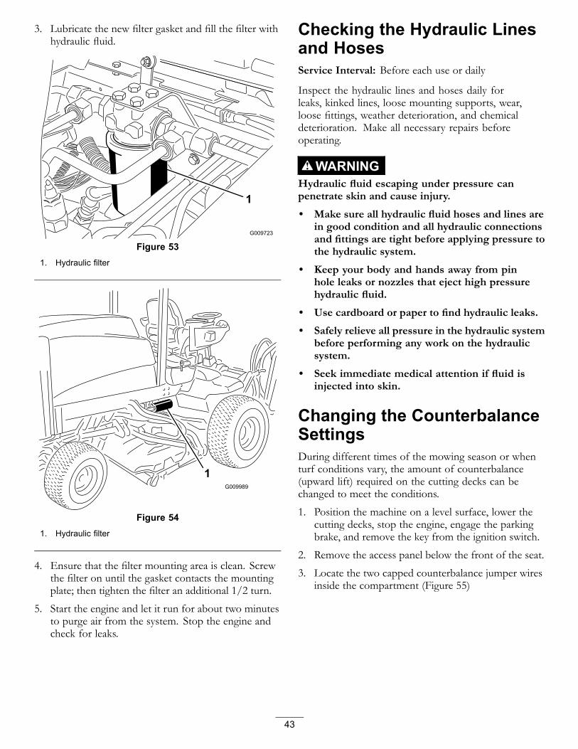
3. Lubricate the new filter gasket and fill the filter withhydraulic fluid.
Figure 531. Hydraulic filter
Figure 541. Hydraulic filter
4. Ensure that the filter mounting area is clean. Screwthe filter on until the gasket contacts the mountingplate; then tighten the filter an additional 1/2 turn.
5. Start the engine and let it run for about two minutesto purge air from the system. Stop the engine andcheck for leaks.
Checking the Hydraulic Linesand HosesService Interval: Before each use or daily
Inspect the hydraulic lines and hoses daily forleaks, kinked lines, loose mounting supports, wear,loose fittings, weather deterioration, and chemicaldeterioration. Make all necessary repairs beforeoperating.
WARNINGHydraulic fluid escaping under pressure canpenetrate skin and cause injury.
• Make sure all hydraulic fluid hoses and lines arein good condition and all hydraulic connectionsand fittings are tight before applying pressure tothe hydraulic system.
• Keep your body and hands away from pinhole leaks or nozzles that eject high pressurehydraulic fluid.
• Use cardboard or paper to find hydraulic leaks.
• Safely relieve all pressure in the hydraulic systembefore performing any work on the hydraulicsystem.
• Seek immediate medical attention if fluid isinjected into skin.
Changing the CounterbalanceSettingsDuring different times of the mowing season or whenturf conditions vary, the amount of counterbalance(upward lift) required on the cutting decks can bechanged to meet the conditions.
1. Position the machine on a level surface, lower thecutting decks, stop the engine, engage the parkingbrake, and remove the key from the ignition switch.
2. Remove the access panel below the front of the seat.
3. Locate the two capped counterbalance jumper wiresinside the compartment (Figure 55)
43

Figure 551. Counterbalance jumper
wires2. Wire cap
4. With the key in the OFF position, remove the capfrom jumper wires and plug the wires together(Figure 56).
Figure 56
5. Turn the key to the RUN position but DO NOTstart the machine.
6. The current counterbalance setting will flash on thediagnostic light. The system allows for 3 settings.
7. The counterbalance setting is changed by usingthe center Raise-Lower switch. To change thecounterbalance setting proceed as follows:• Moving the switch forward to the lower position
and releasing it will lower the counterbalancesetting, thus increasing the effective weight ofeach cutting deck in the turf
• Moving the switch rearward to the raise positionand releasing it will increase the counterbalancesetting, thus decreasing the effective weight ofeach cutting deck in the turf
• After the switch is released, the diagnostic lightwill flash the new counterbalance setting (1, 2,or 3).
8. When the desired setting is attained, rotate the keyto the Off position.
9. Unplug the jumper wires, install the cap on the wiresand put the wires back into the compartment.
10. Replace the access cover.
Note: The machine cannot be operated while inthe counterbalance adjustment mode. Once theadjustment has been completed, move the machineto a test area and operate the machine with thenew setting. The new counterbalanced setting maychange the effective height of cut.
44

CleaningServicing the Spark ArrestorMufflerService Interval: Every 200 hours
Every 200 hours operation, clear the muffler of carbonbuildup.
1. Remove the pipe plug from the clean-out port at thelower side of the muffler.
CAUTIONThe muffler may be hot and could cause injury.
Be careful while working around the muffler.
2. Start the engine. Plug the normal muffler exit with ablock of wood or metal plate so that the exhaust flowwill be forced out of the clean-out port. Continue toblock the exit until carbon deposits cease comingout of the port.
CAUTIONDo not stand in line with the clean-out port.
Always wear safety glasses.
3. Stop the engine and replace the pipe plug.
StorageTraction Unit1. Thoroughly clean the traction unit, cutting units, and
the engine.2. Check the tire pressure; refer to Checking the Tire
Pressure.3. Check all fasteners for looseness; tighten as
necessary.4. Grease or oil all grease fittings and pivot points.
Wipe up any excess lubricant.5. Lightly sand and use touch-up paint on painted areas
that are scratched, chipped, or rusted. Repair anydents in the metal body.
6. Service the battery and cables as follows:A. Remove the battery terminals from the battery
posts.B. Clean the battery, terminals, and posts with a
wire brush and baking soda solution.C. Coat the cable terminals and battery posts with
Grafo 112X skin-over grease (Toro Part No.505-47) or petroleum jelly to prevent corrosion.
D. Slowly recharge the battery every 60 days for 24hours to prevent lead sulfation of the battery.
7. Engage the transport latches (Groundsmaster4700–D only).
Engine1. Drain the engine oil from the oil pan and install the
drain plug.2. Remove and discard the oil filter. Install a new oil
filter.3. Refill the oil pan with 10 qt. (9.5 l) of SAE 15W-40
CH-4, CI-4, higher motor oil.4. Start the engine and run it at idle speed for
approximately two minutes.5. Stop the engine.6. Flush the fuel tank with fresh, clean diesel fuel.7. Secure all of the fuel system fittings.8. Thoroughly clean and service the air cleaner
assembly.9. Seal the air cleaner inlet and the exhaust outlet with
weatherproof tape.10. Check the anti freeze protection and add a 50/50
solution of water and ethylene glycol anti-freeze asneeded for the expected minimum temperature inyour area.
45

Schematics
Hydraulic Schematic-Groundsmaster 4700 (Rev. A)
46

Hydraulic Schematic-Groundsmaster 4500 (Rev. A)
47

Electrical Schematic (Rev. A)
48

Electrical Schematic (Rev. A)
49

Electrical Schematic (Rev. A)
50

Electrical Schematic (Rev. A)
51

The Toro Total Coverage GuaranteeA Limited Warranty
Conditions and Products CoveredThe Toro® Company and its affiliate, Toro Warranty Company, pursuantto an agreement between them, jointly warrant your Toro Commercialproduct (“Product”) to be free from defects in materials or workmanshipfor two years or 1500 operational hours*, whichever occurs first. Thiswarranty is applicable to all products with the exception of Aerators(refer to separate warranty statements for these products). Where awarrantable condition exists, we will repair the Product at no cost to youincluding diagnostics, labor, parts, and transportation. This warrantybegins on the date the Product is delivered to the original retail purchaser.* Product equipped with an hour meter.
Instructions for Obtaining Warranty ServiceYou are responsible for notifying the Commercial Products Distributor orAuthorized Commercial Products Dealer from whom you purchased theProduct as soon as you believe a warrantable condition exists. If you needhelp locating a Commercial Products Distributor or Authorized Dealer, orif you have questions regarding your warranty rights or responsibilities,you may contact us at:
Commercial Products Service DepartmentToro Warranty Company8111 Lyndale Avenue SouthBloomington, MN 55420-1196E-mail: [email protected]
Owner ResponsibilitiesAs the Product owner, you are responsible for required maintenanceand adjustments stated in your Operator’s Manual. Failure to performrequired maintenance and adjustments can be grounds for disallowing awarranty claim.
Items and Conditions Not CoveredNot all product failures or malfunctions that occur during the warrantyperiod are defects in materials or workmanship. This warranty does notcover the following:
• Product failures which result from the use of non-Toro replacementparts, or from installation and use of add-on, or modified non-Torobranded accessories and products. A separate warranty may beprovided by the manufacturer of these items.
• Product failures which result from failure to perform recommendedmaintenance and/or adjustments. Failure to properly maintain yourToro product per the Recommended Maintenance listed in theOperator’s Manual can result in claims for warranty being denied.
• Product failures which result from operating the Product in anabusive, negligent or reckless manner.
• Parts subject to consumption through use unless found to bedefective. Examples of parts which are consumed, or used up, duringnormal Product operation include, but are not limited to, brakespads and linings, clutch linings, blades, reels, bed knives, tines,spark plugs, castor wheels, tires, filters, belts, and certain sprayercomponents such as diaphragms, nozzles, and check valves, etc.
• Failures caused by outside influence. Items considered to be outsideinfluence include, but are not limited to, weather, storage practices,contamination, use of unapproved coolants, lubricants, additives,fertilizers, water, or chemicals, etc.
• Normal noise, vibration, wear and tear, and deterioration.
• Normal “wear and tear” includes, but is not limited to, damage toseats due to wear or abrasion, worn painted surfaces, scratcheddecals or windows, etc.
PartsParts scheduled for replacement as required maintenance are warrantedfor the period of time up to the scheduled replacement time for that part.Parts replaced under this warranty are covered for the duration of theoriginal product warranty and become the property of Toro. Toro willmake the final decision whether to repair any existing part or assembly orreplace it. Toro may use remanufactured parts for warranty repairs.
Note Regarding Deep Cycle Battery Warranty:Deep cycle batteries have a specified total number of kilowatt-hours theycan deliver during their lifetime. Operating, recharging, and maintenancetechniques can extend or reduce total battery life. As the batteries in thisproduct are consumed, the amount of useful work between chargingintervals will slowly decrease until the battery is completely worn out.Replacement of worn out batteries, due to normal consumption, is theresponsibility of the product owner. Battery replacement may be requiredduring the normal product warranty period at owner’s expense.
Maintenance is at Owner’s ExpenseEngine tune-up, lubrication cleaning and polishing, replacement ofItems and Conditions Not Covered filters, coolant, and completingRecommended Maintenance are some of the normal services Toroproducts require that are at the owner’s expense.
General ConditionsRepair by an Authorized Toro Distributor or Dealer is your sole remedyunder this warranty.
Neither The Toro Company nor Toro Warranty Company is liable forindirect, incidental or consequential damages in connection with theuse of the Toro Products covered by this warranty, including anycost or expense of providing substitute equipment or service duringreasonable periods of malfunction or non-use pending completionof repairs under this warranty. Except for the Emissions warrantyreferenced below, if applicable, there is no other express warranty.
All implied warranties of merchantability and fitness for use are limited tothe duration of this express warranty. Some states do not allow exclusionsof incidental or consequential damages, or limitations on how long animplied warranty lasts, so the above exclusions and limitations may notapply to you.
This warranty gives you specific legal rights, and you may also have otherrights which vary from state to state.
Note regarding engine warranty:The Emissions Control System on your Product may be covered bya separate warranty meeting requirements established by the U.S.Environmental Protection Agency (EPA) and/or the California AirResources Board (CARB). The hour limitations set forth above do notapply to the Emissions Control System Warranty. Refer to the EngineEmission Control Warranty Statement printed in your Operator’s Manualor contained in the engine manufacturer’s documentation for details
Countries Other than the United States or CanadaCustomers who have purchased Toro products exported from the United States or Canada should contact their Toro Distributor (Dealer) to obtainguarantee policies for your country, province, or state. If for any reason you are dissatisfied with your Distributor’s service or have difficulty obtainingguarantee information, contact the Toro importer. If all other remedies fail, you may contact us at Toro Warranty Company.
374-0253 Rev A


