33 01 30.81 Sanitary Sewerage Manhole Rehabilitation… 01... · 33 01 30.81 sanitary sewerage...
24
American States Utility Services 33 01 30.81-1 Sanitary Sewerage Manhole Rehabilitation Revision Date: 03/08/2016 33 01 30.81 SANITARY SEWERAGE MANHOLE REHABILITATION PART 1 – GENERAL 1.1 SUMMARY A. The work specified in this section includes all labor, materials, accessories, equipment and tools necessary for the repair and rehabilitation of the sanitary sewer manholes shown on the plans. B. Manhole Rehabilitation as shown in the contract documents includes cleaning manhole, filling all voids, stopping all leaks by chemical grout injection, and applying a spray on liner on the bench, barrel, and cone (terminating at the frame), or providing FRP insert liners, or providing polymer concrete insert liners for the existing manholes. C. The intent and purpose of these specifications is to require a complete and satisfactory installation in every respect and any defect in material or workmanship shall be cause for the replacement and correction of such defect as directed by the Utility’s Representative at no expense to the Utility. 1.2 QUALITY ASSURANCE A. Coating System 1. Coating system manufacturer shall have a minimum 5 years of experience manufacturing the particular material provided for this project, or be approved by the Utility. 2. Coating material must be applied by a Certified Applicator of the coating system manufacturer with at least 5 years of experience with the particular coating being used for this project. B. FRP and Polymer Concrete Liners 1. Regulatory Requirements: a. Comply with Utility requirements. b. Comply with all State and Local Regulatory standards. 2. The installing contractor shall demonstrate applicable experience and performance history by submitting references from a minimum of 3 other rehabilitation projects or shall have a minimum of five years’ experience installing standard sanitary manholes and a certification of training from the manufacturer of the manhole insert system.
Transcript of 33 01 30.81 Sanitary Sewerage Manhole Rehabilitation… 01... · 33 01 30.81 sanitary sewerage...
American States Utility Services 33 01 30.81-1 Sanitary Sewerage Manhole Rehabilitation Revision Date: 03/08/2016
33 01 30.81 SANITARY SEWERAGE MANHOLE REHABILITATION
PART 1 – GENERAL
1.1 SUMMARY
A. The work specified in this section includes all labor, materials, accessories, equipment and tools necessary for the repair and rehabilitation of the sanitary sewer manholes shown on the plans.
B. Manhole Rehabilitation as shown in the contract documents includes cleaning manhole, filling all voids, stopping all leaks by chemical grout injection, and applying a spray on liner on the bench, barrel, and cone (terminating at the frame), or providing FRP insert liners, or providing polymer concrete insert liners for the existing manholes.
C. The intent and purpose of these specifications is to require a complete and satisfactory installation in every respect and any defect in material or workmanship shall be cause for the replacement and correction of such defect as directed by the Utility’s Representative at no expense to the Utility.
1.2 QUALITY ASSURANCE
A. Coating System
1. Coating system manufacturer shall have a minimum 5 years of experience manufacturing the particular material provided for this project, or be approved by the Utility.
2. Coating material must be applied by a Certified Applicator of the coating system manufacturer with at least 5 years of experience with the particular coating being used for this project.
B. FRP and Polymer Concrete Liners
1. Regulatory Requirements:
a. Comply with Utility requirements.
b. Comply with all State and Local Regulatory standards.
2. The installing contractor shall demonstrate applicable experience and performance history by submitting references from a minimum of 3 other rehabilitation projects or shall have a minimum of five years’ experience installing standard sanitary manholes and a certification of training from the manufacturer of the manhole insert system.
American States Utility Services 33 01 30.81-2 Sanitary Sewerage Manhole Rehabilitation Revision Date: 03/08/2016
3. Certification and Testing
a. As a basis of acceptance the manufacturer shall provide an independent certification which consists of a copy of the manufacturer's test report and accompanied by a copy of the test results stating that the manufacturer's manhole liner has been sampled, tested, and inspected in accordance with the provisions of this specification and meets all requirements.
4. Marking and Identification
a. Each manhole liner shall be marked on the inside and outside with the following information:
1) Manufacturer's name or trademark
2) Manufacturer's factory location
3) Manufacturer's serial number
4) Total length
1.3 SUBMITTALS
A. The Contractor shall submit the following prior to construction and use:
1. Product Data shall be submitted for each type of product indicated.
2. Shop Drawings:
a. Detail of FRP and Polymer Concrete liners. Including plans, elevations, sections, details and frames and covers
b. Field quality-control test reports.
c. Traffic Control Plans.
d. Manhole Liner Certification.
1.4 WARRANTY
A. All work shall be certified by the Contractor and manufacturer for specified material properties for a period of two years from the date of acceptance. During the warranty period, any defects which affect the integrity or strength of the product or its ability to perform the in the application specified shall be repaired at the Contractor’s expense in a mutually agreed upon manner.
American States Utility Services 33 01 30.81-3 Sanitary Sewerage Manhole Rehabilitation Revision Date: 03/08/2016
1.5 PROJECT CONDITIONS
A. The Contractor shall visit each site and examine the local conditions to be encountered, improvements to be protected, permits and fees required, and other research necessary to assure Contractor understands the project thoroughly and is fully aware of all conditions and constraints which may be encountered during the course of construction.
B. Contractor shall conduct excavation and backfill operations in such a manner as to cause no damage to any existing utility, or impact safety for the public or the contractor’s employees during and after construction.
C. The Contractor shall meet all of the applicable OSHA regulations and all applicable requirements of EM385.
D. The Contractor shall provide a system to capture and remove cleaning material from the wet well without entry into the wetwell.
E. The Contractor shall be responsible for all traffic control requirements. This shall include flagging, all applicable signage, and/or detours as designated by the more stringent of the the Base Installation Design Guide (IDG), DOT requirements, and the MUTCD design manual (latest editions)
F. The Contractor shall provide Utility with a minimum three week notice of road closures.
G. The Contractor shall provide all means necessary to prevent sewer service impact to the user. This shall be resolved by the use of plugging clean outs, placing inflatable rubber balls in toilets, ensuring user toilet seat is down and secured, etc.
H. Service to occupied facilities shall not be interrupted unless permitted under the following conditions and then only after arranging to provide temporary water and sewer service according to requirements indicated:
1. Notify Utility no fewer than two days in advance of proposed interruption of service.
2. Do not proceed with interruption of sewer collection service without Utility’s written permission.
3. Sewer service interruption shall be limited to four hours or less.
4. In Cases where service is interrupted for longer than four hours, the contractor shall provide bottled water and portable toilets to the facility being impacted in quantities determined by the Utility at no additional cost to the Utility.
American States Utility Services 33 01 30.81-4 Sanitary Sewerage Manhole Rehabilitation Revision Date: 03/08/2016
PART 2 – PRODUCTS
2.1 PATCHING MATERIAL
A. All non-leaking holes, cracks or voids shall be patched with a quick setting (less than 30 minutes), non-shrink, fiber reinforced, corrosion resistant calcium aluminate or equivalent material that is compatible with the chosen liner system and shall be applied in accordance with the manufacturer’s recommendation for basecoat materials. Patch material must meet the following minimum requirements:
1. Compressive Strength per ASTM C-109: >200 psi (1 Hour)
2. Ultimate Compressive Strength per ASTM C-109: 5000 psi
3. Bond Strength per ASTM C-882: >1700 psi
4. Applied Density: 105 pcf
5. Shrinkage per ASTM C-596: 0% at 90% R.H.
2.2 INFILTRATION CONTROL MATERIAL (CHEMICAL GROUT)
A. Active leaks and infiltration shall be stopped by injecting a chemical grout through the source to the outside of the manhole. The grout used shall be an acrylamide, acrylic or hydrophobic urethane gel and might require the addition of a shrink control agent, gel reinforcing agent or accelerator. The chemical grout shall be volume stable and have a minimum 28 day compressive strength of 250 psi and minimum one day strength of 50 psi.
2.3 CEMENTITIOUS LINER
A. The material shall be a 100% calcium aluminate mortar designed to stop infiltration, restore structural integrity, and provide protection against microbiologically-induced corrosion. It shall be spray applied to form a structurally enhanced monolithic liner covering all interior substrate surfaces with the following minimum requirements:
1. Compressive Strength per ASTM C-109: >8000 psi (28 Days)
2. Tensile Strength per ASTM C-900: >800 psi
3. Flexural Strength per ASTM C-293: >1200 psi (28 Days)
4. Shrinkage @ 90% R.H. per ASTM C-596: <0.08% (28 Days)
5. Freeze/Thaw per ASTM C-666: No Damage After 300 Cycles
6. Air Void Content per ASTM C-457: 2-4% (7 Days)
American States Utility Services 33 01 30.81-5 Sanitary Sewerage Manhole Rehabilitation Revision Date: 03/08/2016
7. Specific Gravity/Absorption Test per ASTM C-642: 3-5% (7 Days)
B. Cementitious liner shall be Quadex Aluminaliner, manufactured by Quadex, Inc.; SewperCoat, manufactured by LaFarge Aluminates, CemTec Silatec CAM, manufactured by A. W. Cook Cement, Inc.; Strong-Seal MS2-C, High Performance Mix manufactured by Strong-Seal Systems, PerpetuCrete CA, manufactured by Protective Liner Systems, or approved equal.
2.4 EPOXY LINER
A. The material shall be 100% solids, solvent-free two-component epoxy resin system with select fillers to minimize permeability and provide sag resistance acceptable to the following minimum requirements:
1. Hardness, Shore D per ASTM D-2240: 70
2. Tensile Strength per ASTM D-638: >7000 psi
3. Flexural Strength per ASTM D-790: >10000 psi
B. Epoxy liner shall be Raven 405, manufactured by Raven Lining Systems, Cor-Cote SC, manufactured by Sherwin-Williams, PerpertuCoat PLS-613 manufactured by Protective Liner Systems, or approved equal.
2.5 FRP MANHOLE LINERS
A. The resins used shall be a commercial grade unsaturated polyester resin or vinyl ester resin.
B. The reinforcing materials shall be commercial grade "e" type glass in the form of continuous roving and chop roving, having a coupling agent that will provide a suitable bond between the glass reinforcement and the resin.
C. Interior Surfacing Material
1. The inner surface exposed to the chemical environment shall be a resin-rich layer of 0.010 to 0.020 inch thick.
2. The inner surface layer exposed to the corrosive environment shall be followed with a minimum of two passes of chopped roving of minimum length 0.5 inch (13 mm) to maximum length of 2.0 inch (50.8 mm) and shall be applied uniformly to an equivalent weight of 3 oz./ft.
3. Each pass of chopped roving shall be well rolled prior to the application of additional reinforcement.
4. The combined thickness of the inner surface and interior layer shall not be less than 0.10 inch (2.5 mm)
D. Wall Construction Procedure
American States Utility Services 33 01 30.81-6 Sanitary Sewerage Manhole Rehabilitation Revision Date: 03/08/2016
1. After inner layer has been applied the manhole liner wall shall be constructed with chop and continuous strand filament wound manufacturing process which insures continuous reinforcement and uniform strength and composition.
2. The cone section, if produced separately, shall be affixed to the barrel section at the factory with resin-glass reinforced joint resulting in a one piece unit.
3. Seams shall be fiberglassed on the inside and the outside using the same glass-resin jointing procedure.
4. Field joints shall not be acceptable by anyone except the manufacturer.
E. UV inhibitor shall be applied to the exterior surface of the manhole liner and shall have gray pigment and shall be a minimum thickness .125 inches.
F. Fillers And Additives
1. Fillers, when used, shall be inert to the environment and manhole construction.
2. Sand shall not be accepted as an approved filler.
3. Additives, such as thixotropic agents, catalysts, promoters, etc., may be added as required by the specific manufacturing process to be used to meet the requirements of this standard. The resulting reinforced-plastic material must meet the requirements of this specification.
G. Manhole Liner Design
1. All manholes shall have a 0.50” minimum wall thickness. 2. All manhole liners shall be designed so that a ladder can be supported by
the installed manhole liner. No manhole steps shall be installed.
3. Manway cone sections shall be concentric with respect to the larger portion of the manhole liner diameters through 60 inches. Larger manhole liners may have concentric or eccentric manway reducer openings.
4. The manhole liner shall provide an area for which grade rings to be installed to accept a manhole frame and cover and have the strength to support a traffic load without damage to the manhole liner.
American States Utility Services 33 01 30.81-7 Sanitary Sewerage Manhole Rehabilitation Revision Date: 03/08/2016
H. Other Requirements
1. The exterior surface of the liner shall be relatively smooth with no sharp projections. Hand-work finish is acceptable if enough resin is present to eliminate fiber show. The exterior surface shall be free of blisters larger than 0.5 inch in diameter, delamination or fiber show.
2. The interior surface shall be resin rich with no exposed fibers. The surface shall be free of crazing, delamination, blisters larger than 0.5 inch in diameter and wrinkles of 0.125 inch or greater in depth. Surface pits shall be permitted if they are less than 0.75 inch in diameter and less than 0.0625 inch deep. Voids that cannot be broken with finger pressure and that are entirely below the resin surface shall be permitted if they are less than 0.5 inch in diameter and less than 0.0625 inch thick.
3. Any manhole liner repairs shall meet all requirements of this specification.
4. Manhole liner lengths shall be in 6-inch increments +/- 2 inches.
5. Tolerance of inside diameter shall be +/- 1% of required manhole diameter.
6. The complete manhole liner shall have a minimum dynamic-load rating of 16,000 lbs. when tested in accordance with ASTM 3753 8.4 (note 1). To establish this rating the complete manhole shall not leak, crack, or suffer other damage when load tested to 40,000 lbs. and shall not deflect vertically downward more than 0.25 in. at the point of load application when loaded to 24,000 lbs.
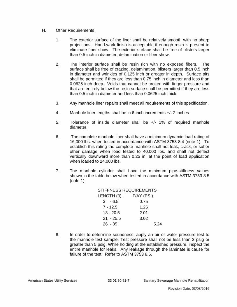
7. The manhole cylinder shall have the minimum pipe-stiffness values shown in the table below when tested in accordance with ASTM 3753 8.5 (note 1).
STIFFNESS REQUIREMENTS LENGTH (ft) F/AY (PSI)
3 - 6.5 0.75 7 - 12.5 1.26 13 - 20.5 2.01 21 - 25.5 3.02 26 - 35 5.24
8. In order to determine soundness, apply an air or water pressure test to
the manhole test sample. Test pressure shall not be less than 3 psig or greater than 5 psig. While holding at the established pressure, inspect the entire manhole for leaks. Any leakage through the laminate is cause for failure of the test. Refer to ASTM 3753 8.6.
American States Utility Services 33 01 30.81-8 Sanitary Sewerage Manhole Rehabilitation Revision Date: 03/08/2016
9. The FRP manhole and all related components shall be fabricated from corrosion proof material suitable for atmospheres containing hydrogen sulfide and dilute sulfuric acid as well as other gases associated with the wastewater collection systems.
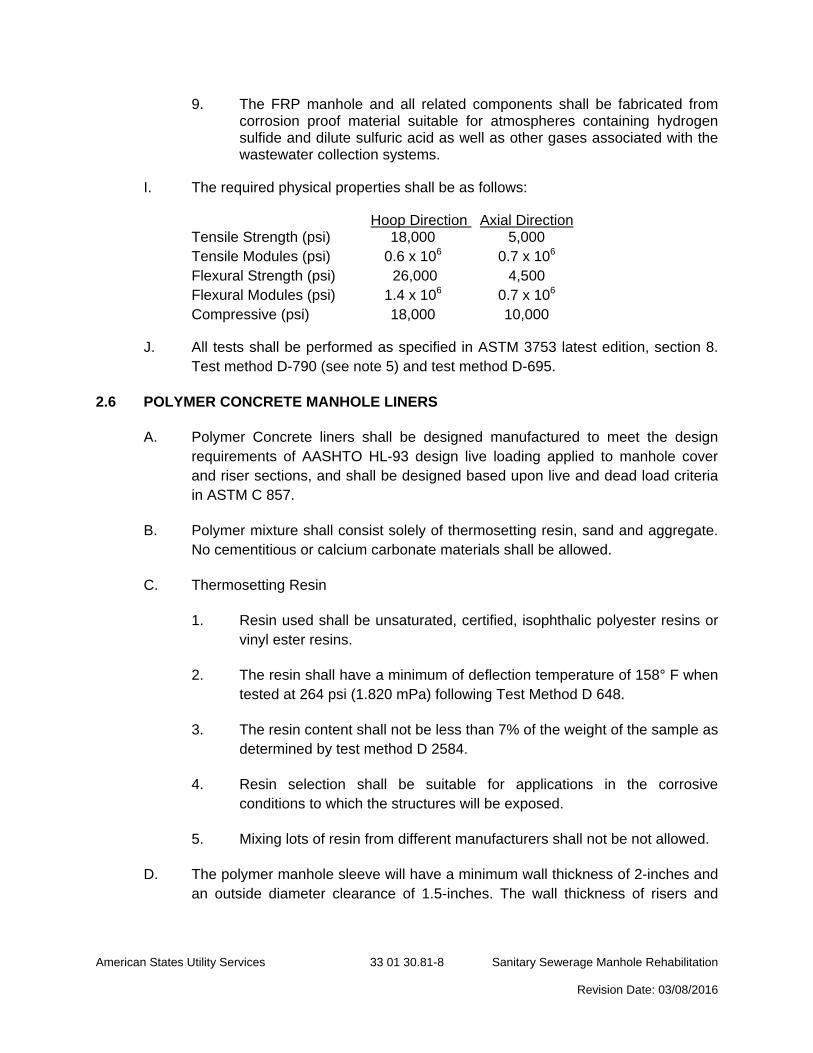
I. The required physical properties shall be as follows:
Hoop Direction Axial Direction Tensile Strength (psi) 18,000 5,000 Tensile Modules (psi) 0.6 x 10⁶ 0.7 x 10⁶ Flexural Strength (psi) 26,000 4,500 Flexural Modules (psi) 1.4 x 10⁶ 0.7 x 10⁶ Compressive (psi) 18,000 10,000
J. All tests shall be performed as specified in ASTM 3753 latest edition, section 8. Test method D-790 (see note 5) and test method D-695.
2.6 POLYMER CONCRETE MANHOLE LINERS
A. Polymer Concrete liners shall be designed manufactured to meet the design requirements of AASHTO HL-93 design live loading applied to manhole cover and riser sections, and shall be designed based upon live and dead load criteria in ASTM C 857.
B. Polymer mixture shall consist solely of thermosetting resin, sand and aggregate. No cementitious or calcium carbonate materials shall be allowed.
C. Thermosetting Resin
1. Resin used shall be unsaturated, certified, isophthalic polyester resins or vinyl ester resins.
2. The resin shall have a minimum of deflection temperature of 158° F when tested at 264 psi (1.820 mPa) following Test Method D 648.
3. The resin content shall not be less than 7% of the weight of the sample as determined by test method D 2584.
4. Resin selection shall be suitable for applications in the corrosive conditions to which the structures will be exposed.
5. Mixing lots of resin from different manufacturers shall not be not allowed.
D. The polymer manhole sleeve will have a minimum wall thickness of 2-inches and an outside diameter clearance of 1.5-inches. The wall thickness of risers and
American States Utility Services 33 01 30.81-9 Sanitary Sewerage Manhole Rehabilitation Revision Date: 03/08/2016
conical tops shall be not less than that prescribed by the manufacturer’s design by more than 5%.
E. Steel reinforcement shall not be required for circumferential reinforcement, joint reinforcement, or hoop reinforcement. Manufacture will determine the need for and type of reinforcement as it pertains to safety and lifting requirements.
F. Variations in height of two opposite sides of risers and conical tops shall not be more the 5/8 inch. The under run in height of a riser or conical top shall not be more than ¼-inch /foot of height with a maximum of ½-inch in any one section.
G. Riser and cone section joints shall be of a flush flat edge design that on assembly with gaskets and/or butyl mastic will make a continuous and uniform manhole. Joint sealing surfaces shall be free of dents, gouges and other surface irregularities that would affect joint integrity.
H. Polymer manhole riser and cone sections are to be provided in various lengths in combination to provide correct height with the fewest joints.
I. Each manhole component shall be free of all defects that will detrimentally affect the strength and serviceability of the component part.
J. Epoxy coatings for bench area shall meet the requirements of Section 2.4 above.
2.7 MANHOLE FRAME AND COVER
A. Manhole Frames and Covers shall be ferrous; 24-inch ID by 7- to 9-inch riser, with 4-inch- minimum-width flange and 26-inch diameter cover. Include indented top design with lettering cast into cover, using wording equivalent to "SANITARY SEWER." Outside ring on sewer manholes shall be painted APWA Green (PMS 3415).
B. Material shall be ASTM A 48-43, Class 35 gray iron unless otherwise indicated.
C. Cast Iron covers and frames design shall be based on a wheel load of 15,000 pounds plus 25% allowance for impact and the use of class 20 cast iron (federal spec RR-F 621C). Other designs differing only in non-essential details and as approved by the Owner may be used. Total weight shall be at least 400 pounds.
D. Manhole frame and cover shall be manufactured by the same manufacturer.
E. All castings shall conform to the shape and dimensions shown on the plans, and shall be clean and perfect without blow, sand holes, or defects of any kind which tend to impair their strength. No plugging or other stopping of defect holes will be allowed.
American States Utility Services 33 01 30.81-10 Sanitary Sewerage Manhole Rehabilitation Revision Date: 03/08/2016
F. The manhole ring and cover shall be set into a bed of clean, fresh mortar and/or a concrete collar as indicated on Utility’s Standard Details, in order to place the ring and cover at the required grade.
G. Camlock ring and covers shall have wiper gasket and two stainless steel roll pins ½-inch diameter by 1-3/4 inches 180 apart on the manhole cover. Camlock bolt head shall be compatible with Owner standard tool for turning camlock mechanism. Camlock ring and covers shall be installed as indicated on the drawings, in accordance with Owner standard details.
2.6 FRAME/CONE SEAL
A. Applied seals shall be achieved by applying an aromatic urethane resin compound to the internal surface between the manhole frame and the cone section to stop inflow under the manhole frame. Sufficient material shall be applied to achieve a minimum thickness of 120 mils. The material shall comply with the following requirements:
1. Hardness per ASTM D-2240: 75
2. Tensile Strength per ASTM D-412: 1150 psi
3. Elongation per ASTM D-442: 800%
4. Adhesive Strength per ASTM D-903: 175 lb/l. inch
5. Tear Resistance per ASTM D-1004: 155 lb/l. inch
B. The material shall be Flex-Seal Utility Sealant as manufactured by Sealing Systems, Inc. or approved equal.
2.5 INFLOW COLLECTOR
A. The contractor shall supply and install, to the manufacturer's recommendations, manhole inflow collectors as specified hereafter.
B. The completed manhole inflow collector and its associated valve body and components shall be manufactured from corrosion proof material suitable for atmospheres containing hydrogen sulfide and dilute sulfuric acid as well as other gases associated with wastewater collection systems.
C. The inflow collector shall be equipped with a gas relief valve designed to relieve at a pressure of 1 psi and have a water leak down rate not to exceed 5 gallons per 24 hours.
D. The insert gasket shall be made of closed cell neoprene and have a pressure sensitive adhesive on one side and be placed under the insert body rim by the manufacturer. The adhesive shall be compatible with the insert body material so as to form a long lasting bond in either wet or dry conditions of use.
American States Utility Services 33 01 30.81-11 Sanitary Sewerage Manhole Rehabilitation Revision Date: 03/08/2016
E. The inflow collector shall be equipped with a non-deteriorating lifting strap strong enough to lift a collector full to capacity with water out of the manhole. The lifting strap shall be fastened to the insert body with stainless steel rivets.
2.6 INSIDE DROP BOWL
A. Inside manhole drops shall be installed where indicated on the Repair Schedule.
B. Inside Drop Bowl size shall be determined by incoming pipe sizes and approximate flow rates. The bowl shall be installed as per manufacturer’s instructions using stainless steel fasteners.
C. The drop pipe and turn-out at the base end of the drop pipe shall be PVC SDR 35 (main lines) or Sch. 40 (service laterals). The turn-out at the base end of the drop pipe shall be accomplished with an appropriately angled pipe elbow.
D. All brackets for attaching the drop pipe to inside of manhole shall be stainless steel adjustable clamping brackets and fasteners anchored to the manhole wall.
E. Inside drop bowls shall be RELINER Inside Drop Bowl manufactured by RELINER / Duran Inc. or approved equal.
2.7 CONCRETE
A. General: Cast-in-place concrete complying with ACI 318, ACI 350/350R, and the following:
1. Cement: ASTM C 150, Type II.
2. Fine Aggregate: ASTM C 33, sand.
3. Coarse Aggregate: ASTM C 33, crushed gravel.
4. Water: Potable.
B. Portland Cement Design Mix: 4000 psi minimum, with 0.45 maximum water/cementitious materials ratio.
2.8 WATER
A. All water used on this project shall be clean and potable water.
PART 3 – EXECUTION
3.1 FLOW CONTROL AND BYPASS PUMPING:
A. It is anticipated that minimal bypass pumping will be required for manhole rehabilitation. It is expected that the majority of flow control can be accomplished using flow through plugs.
American States Utility Services 33 01 30.81-12 Sanitary Sewerage Manhole Rehabilitation Revision Date: 03/08/2016
B. When force main discharges are encountered, the Contractor may fabricate an apparatus to divert flow toward the bottom of the manhole thus reducing splash. Accepted materials for the temporary apparatus include PVC pipe, bends, fittings, fernco couplings, and lay flat discharge hose (and other acceptable materials / methods presented by the Contractor). The Utility shall assist by hand operating the lift stations while the Contractor installs the flow control apparatus.
C. If the Contractor proposes bypass pumping for this project, a detailed Bypass Pumping Plan shall be submitted by the Contractor, prior to installing any bypass pumping.
3.2 PATCHING HOLES OR VOIDS
A. All loose or disintegrated material shall be removed from the area to be patched.
B. Holes or voids around steps, joints or pipes, spalled areas, and cavities caused by missing or broken brick or mortar shall be repaired using patching material conforming to the requirements of Section 2.1 of these specifications.
C. The patching material shall be mixed and applied in accordance with the manufacturer’s requirements.
3.3 STOPPING ACTIVE LEAKS AND INFILTRATION:
A. All active leaks and infiltration shall be repaired using chemical grout conforming to the requirements of Section 2.2. Any areas that show evidence of leakage either active or non-active during inspection shall be injected.
B. At each point of leakage within the manhole structure a hole shall be carefully drilled through the wall to the exterior of the manhole. Grout ports or sealant injection devices shall be placed in these holes in a way as to provide a watertight seal between the holes and the injection device.
C. Chemical grout shall be pumped through the hole until material refusal is recorded on a pressure gauge mounted on the pumping unit. Care shall be taken during the pumping operation to insure that excessive pressures do not develop and cause damage to the manhole structure.
D. Upon completion of the injection, the ports shall be removed and the remaining holes filled with mortar and troweled flush with the surface of the manhole wall.
E. The injected section joints, pipe connection, holes, or seams shall be sealed with patching material conforming to the requirements of Section 2.1 and smoothed flush with the surface of the manhole wall.
F. To prevent the migration of infiltration leaks the Contractor shall comply with the following requirements for points of injection:
1. For Pre-cast Section Joint Leaks, provide a minimum of 4 injection points shall be evenly spaced around the circumference of the manhole joint.

American States Utility Services 33 01 30.81-13 Sanitary Sewerage Manhole Rehabilitation Revision Date: 03/08/2016
2. For Pipe Connection Leaks, provide a minimum of 2 injection points shall be evenly spaced around pipe connection. Large diameter pipe may require more than 2 injection points.
3. For Pipe Invert Leaks, provide a minimum of 2 injection points, one on each side of trough.
4. For Lift Holes / Voids provided a minimum of 1 injection point below the center of the lift hole / void.
3.4 REFORM/REPAIR EXISTING BENCH AND INVERT
A. Manhole inverts and benches shall be reformed as identified in the plans using the patching material identified in Section 2.1. Fast setting hydraulic cement may be used to repair the invert.
B. The patch material shall be applied to the invert and bench at a minimum thickness of ½”, extending sufficiently to the wall to tie into the cementitious liner to be applied later.
C. The finished invert and bench shall be troweled to a smooth finish free of any ridges.
D. The bench shall be sloped a minimum of 2 inches from the manhole wall toward the invert to prevent debris build-up on the bench.
E. Repairs on the invert shall not compromise grade.
F. The invert and bench shall be allowed to cure for a minimum of 30 minutes before being subject to active flow. Flow shall be bypassed by the requirements of Section 2: Wastewater Flow Control
3.5 BUILDING BENCH AND INVERT
A. Inverts and benches shall be constructed in manholes with no hard bottom and no defined invert (channel of flow) using the patching material identified in Section 2.1. Fast setting hydraulic cement may be used to repair the invert.
B. The bench shall be constructed of brick or block and finished by troweling smooth with patching material.
C. The patching material shall have a minimum thickness of 1”.
D. The finished invert and bench shall be troweled to a smooth finish free of any ridges.
E. The bench shall be sloped from the manhole wall toward the invert to prevent debris build-up on the bench. The invert and bench shall be allowed to cure for a minimum of 30 minutes before being subject to active flow.

American States Utility Services 33 01 30.81-14 Sanitary Sewerage Manhole Rehabilitation Revision Date: 03/08/2016
F. Flow shall be bypassed by the requirements of Section 3.1.
3.6 CEMENTITIOUS LINER APPLICATION
A. Surface Preparation:
1. All foreign material shall be removed from the manhole wall and bench using a high-pressure water spray (minimum 5,000 psi).
2. Loose or protruding brick, mortar and concrete shall be removed using a mason’s hammer and chisel or scraper. All concrete or mortar that is not sound or has been damaged by chemical exposure shall be removed to a sound concrete surface.
3. All loose cementitious liner (previously installed) shall be removed by water blasting. Deteriorated epoxy or protective coatings shall be completely removed by sandblasting.
4. Any holes or voids shall be filled in accordance with Section 3.2. The surface to be repaired must be clean and free of any loose materials.
5. Active leaks and infiltration shall be stopped in accordance with Section 3.3.
B. Step Removal:
1. Prior to application of the cementitious liner, all steps shall be cut off and ground flush with the manhole wall. The contractor shall be responsible for the removal and disposal of old steps.
C. Liner Application:
1. No application shall be made to frozen surfaces or if freezing is expected to occur inside the manhole within 24 hours after application. If ambient temperatures are in excess of 95 degrees, precautions shall be taken to keep the mix temperature below 90 degrees.
2. For each bag of product, use the amount of water specified by the manufacturer and mix for 30 seconds to 1 minute using equipment per manufacturer’s recommendation.
3. Manhole channels are not required to be lined.
4. First Application:
a. The surface prior to spraying shall be damp without noticeable free water, but totally saturated.
b. Materials shall be applied using low-pressure spray equipment from the bottom of the wall (including the bench but not invert) to the top (terminating at the frame / cone connection), to a minimum uniform
American States Utility Services 33 01 30.81-15 Sanitary Sewerage Manhole Rehabilitation Revision Date: 03/08/2016
thickness to insure that all cracks, crevices, and voids are filled and a relatively smooth surface remains after light troweling.
c. Light troweling shall be performed to compact the material into voids and to set the bond.
5. Second Application:
a. A second application is applied after the first application has begun to take an initial set (disappearance of surface sheen which could be 15 minutes to 1 hour depending upon ambient conditions) to assure a minimum total finished thickness of 1 inch.
b. Application again shall be from the bottom up using low-pressure spray equipment.
c. The surface shall then troweled to a smooth finish being careful not to over trowel so as to bring additional water to the surface and weaken it.
6. Curing:
a. Caution should be taken to minimize exposure of applied product to sunlight and air movement.
b. If application of second coat is to be longer than 15 minutes after completion of first coat, the manhole cover shall be set back in place.
c. At no time should the finished product be exposed to sunlight or air movement for longer than 15 minutes before replacing the manhole cover.
d. The final application shall have a minimum of 4 hours cure time before being subjected to active flow.
e. Flow shall be bypassed per the requirements of Section 3.1.
f. Traffic shall not be allowed over manholes for 12 hours after application is complete.
3.7 EPOXY LINER APPLICATION
A. Surface Preparation:
1. All concrete or mortar that is not sound or has been damaged by chemical exposure shall be removed to a sound concrete surface. At a minimum, this shall be achieved with a low pressure water cleaning equipment using a 0 degree rotating nozzle at 5,000 psi and 4 gpm.

American States Utility Services 33 01 30.81-16 Sanitary Sewerage Manhole Rehabilitation Revision Date: 03/08/2016
2. Other methods such as high pressure water jetting (refer to NACE Standard No. 5/SSPC-SP12), abrasive blasting, shot-blasting, grinding, scarifying, and/or acid etching may also be used.
3. The method(s) used shall be performed in a manner that provides a uniform, sound, clean, neutralized surface that is not excessively damaged.
4. Any holes or voids shall be filled in accordance with Section 3.2. The surface to be repaired must be clean and free of any loose materials.
5. Active leaks and infiltration shall be stopped in accordance with Section 3.3.
6. When required on the plans, the epoxy liner shall be applied over a back-build of cementitious surface.
a. Exact minimum thicknesses of cementitious back-build will be determined after deteriorated concrete has been removed.
b. The cementitious liner shall be applied accordance to Section 3.6 of this specification.
c. The epoxy lining shall take place only after the cementitious liner has cured the appropriate length of time as recommended by the manufacturer.
d. Micro-silica based cementitious material may be substituted for back-build material upon Manufacturer’s recommendations.
B. Liner Application:
1. Spray application equipment approved by the coating manufacturer shall be used.
2. Manhole channels are not required to be lined.
3. Surfaces shall be coated by spray application to a minimum dry film finished thickness of 100 mils including bench (not including invert) and walls (terminating at cone / frame joint). Thickness shall be achieved using a minimum of two coats.
4. Subsequent top coating or additional coats should occur no later than the recoat window for the specified products. Additional surface preparation will be required if this recoat window is exceeded.
C. Spark Test:
1. The cured epoxy lining shall be spark tested for pinholes with a spark tester set at 10,000 volts minimum (100 V per mil).
2. All pinholes identified by the spark test shall be repaired.
American States Utility Services 33 01 30.81-17 Sanitary Sewerage Manhole Rehabilitation Revision Date: 03/08/2016
3. All pinholes shall be marked off on surface areas containing pinholes to a point 6 inches beyond all pinholes and patch with epoxy to a minimum additional thickness of 30 mils.
4. Blisters and uncured lining shall be completely removed and the areas recoated with epoxy to a point 6 inches beyond the repair areas at a minimum thickness of 100 mils.
3.8 FRP MANHOLE LINERS
A. The existing manhole shall be excavated to below the bottom of concrete cone section on the existing manhole. The existing concrete cone section shall be removed and disposed of properly.
B. All cuts through existing asphalt and or concrete pavement shall be saw cut with straight cuts.
C. All existing manhole steps shall be removed flush with the existing manhole wall.
D. FRP manhole liners shall be installed in strict conformance to the manufacturer’s recommendations and specifications. General procedure is as follows:
1. Lift the manhole liner by inserting timber into the opening at the top of the liner. Attach a rope or chain to the timber and lift with a backhoe or other lifting device.
2. Set the manhole liner into existing manhole. Mark the contour of the existing bench area onto the FRP liner. Remove the liner and cut along the contour mark.
3. Set the liner into the existing manhole in a concentric manner. Use a non-shrinking grout to seal the area between the bottom of the liner and the existing bench area.
4. The area between the old manhole and the new FRP manhole liner shall be filled using a concrete grout or flowable fill. The concrete grout shall be poured in layers of not more than 12 inches in even lifts. Backfill around the excavated reducer section with stabilized sand or crushed stone. The material chosen shall be free of large lumps or clods which will not readily break down under compaction. Backfill material and compaction requirements shall be in accordance with Section 31 20 00 Earth Moving.
E. Any required manhole wall penetrations shall be sealed with a water proof gasket assembly approved by Owner.
F. The manhole frame and cover shall be set on concrete grade rings and into a bed of clean, fresh mortar as indicated on the standard details, in order to place the ring and cover at the required grade. Set tops of frames and covers level with finished surface of manholes that are in pavements. Set tops of frames and covers 3-inches
American States Utility Services 33 01 30.81-18 Sanitary Sewerage Manhole Rehabilitation Revision Date: 03/08/2016
above finished surface in non-pavement areas unless otherwise indicated. Grade rings shall be no more than 6-inches in height.
G. All exposed concrete/grout surfaces within manholes including manhole inverts shall be sealed with a 60 mil coating with Sauereisen Sewer Guard Epoxy spray coating or approved equal.
H. Pavement shall be replaced in kind to match existing pavement depth and material type. Non paved areas shall be replaced in kind to match existing conditions.
3.9 POLYMER CONCRETE MANHOLE LINERS
A. The area around the manhole shall be excavated as necessary to provide for removal of existing cone and castings while preventing soil and debris from falling into the manhole.
B. Contractor shall provide equipment to maintain sewage flows without backup, overflow or spill.
C. Necessary repairs shall be made to the existing manhole in order to receive the polymer inserts.
D. Any loose debris shall be power washed or cleaned from wall areas. All dirt, grease, and debris shall be removed from the bench area to prepare bench surfaces for resurfacing. Debris shall not be allowed to enter the sewage system.
E. All active leaks shall be repaired, and the bench shall be leveled and repaired to prepare for the polymer insert installation.
F. The risers will be offloaded and lifted into place with approved manufacturer’s lifting device. No other handling apparatus shall be acceptable.
G. Installation of First Polymer Riser Section
1. The first polymer riser section shall be saw cut if necessary to accommodate pipe entry and bench slopes.
2. Depending on invert configuration, the bench area shall be prepared by building up the bench section with a Portland cement and sand mixture to provide a clean level surface to receive the riser. This build up should allow for a level surface above the existing top of the highest pipe.
3. If pipe inverts are severely staggered the initial polymer sleeve can be modified in the field to accommodate the difference in bench slopes.
American States Utility Services 33 01 30.81-19 Sanitary Sewerage Manhole Rehabilitation Revision Date: 03/08/2016
4. After grout has set, lower the first riser section, clean and wipe down the polymer riser wall above the bench to allow for application of the epoxy coating. This shall be done with a wet cloth.
5. When the new bench configuration is sufficiently dry and clean, a thin shell coating of the epoxy shall be built over the bench. The epoxy shall should continue 6-inches up the polymer riser face to allow for interlink between the coating and polymer riser section.
6. All non-booted or flexible coupler pipe entry areas shall be grouted by an epoxy patch kit provided by the manufacturer.
H. Completion of Installation
1. After the initial bottom seal has cured the additional remaining riser sections and cone shall be installed using the appropriate wall alignment guides, gaskets and/or mastic.
2. Fill the annular space between old and new structure with 3 parts sand to 1 part cement Portland cement grout or a backfill material approved by the Utility.
3.10 FRAME/CHIMNEY (CONE) SEAL INSTALLATION
A. Applied Seal:
1. All foreign material, bituminous coating, rust or scale build-up, etc. shall be removed from the area to be coated by sandblasting in accordance with the manufacturers requirements. Wire brushing will not be allowed.
2. After the area is cleaned, it must be completely dried prior to application of the seal material.
3. The urethane resin compound shall then be applied from the bottom 3 inches of the frame to the top three inches of the cone, including the grade adjustment area, to a minimum thickness of 120 mils.
4. Application shall be in accordance with the manufacturer’s instructions.
3.11 CLEANING MANHOLE
A. Any rocks, pieces of broken pipe or any other debris not desired in the manhole or invert shall be removed and disposed of by methods deemed appropriate by the engineer.
B. The bench and invert shall be pressure washed to remove organic material and return undisturbed wastewater flow to the invert.
American States Utility Services 33 01 30.81-20 Sanitary Sewerage Manhole Rehabilitation Revision Date: 03/08/2016
3.12 PLUGGING ABANDONED LINE
A. Abandoned lines shall be filled with non-shrink grout conforming to the requirements of Section 2.2.
B. Grout plug shall extend at least 1.5 times the thickness of the manhole wall.
C. Plugging abandoned lines shall be performed prior to cementitious lining.
3.13 RAISING MANHOLES
A. The frame shall be removed from the cone.
B. The top of the cone and bottom of the frame shall receive a SSPC-SP3 Power Tool Cleaning to remove all rust and loose material.
C. Precast Concrete Grade Adjustment Ring:
1. A pre-cast grade ring shall be inserted to raise the manhole with ample butyl rubber mastic applied between the cone and grade ring and the grade ring and the frame.
2. If adjustment is made between the barrel and the cone section, butyl rubber shall be inserted between each joint
D. Steel Grade Adjustment Ring:
1. Silicone shall be used to seat the steel grade adjustment ring on the frame.
2. The grade ring shall be secured to the existing frame by four spot welds spaced equal distance around the circumference of the frame.
3. This method shall only be used to raise manholes prior to asphalt overlay of the road.
3.14 INSTALL FLAT TOP SLAB ON EXISTING SQUARE TOP MANHOLE
A. Existing square top slab, frame, and cover shall be removed.
B. Brick or block courses shall be removed to allow for the installation of new flat top slab to grade.
C. Standard approved precast concrete flat top slabs shall be used when applicable. Where standard size top slabs will not suffice, a custom precast concrete approved flat top slab shall be installed.
D. Frames shall be bolted to the flat top using SS expansion bolts and butyl rubber mastic.
E. The finished elevation shall be level with the existing or proposed finished grade.
American States Utility Services 33 01 30.81-21 Sanitary Sewerage Manhole Rehabilitation Revision Date: 03/08/2016
3.15 REALIGN AND RESET FRAME
A. Manhole frames shall be bolted to the cone section using SS Expansion Bolts. Frame shall have a minimum of 2 bolts (5/8” diameter, 4” in length).
B. Frames shall be sealed to the top of manhole with butyl rubber mastic.
C. Grout shall then be placed, on the inside and outside to the height of the adjustment.
D. Manholes installed in streets or roadways shall be constructed with a concrete ring (3,000 psi) 6 inches thick and 5 foot minimum o.d. securing the frame. The concrete ring shall lie embedded in the gravel base course and below the surface course of pavement.
3.16 MANHOLE BENCH AND CHANNEL
A. Manhole channels and benches shall be removed and rebuilt.
B. Manhole channels and benches shall be field formed from concrete.
1. Channels: Concrete invert, formed to same width as connected piping, with height of vertical sides to three-fourths of pipe diameter. Form curved channels with smooth, uniform radius and slope.
2. Benches: Concrete, sloped to drain into channel.
C. Modify the inverts to provide a smooth flow line through the manhole.
D. Raise the bench to the top of the pipe, forming a "U" channel through the manhole and provide sufficient slope to make benches self-cleaning when benches must be modified.
3.17 GROUTING SECTION JOINTS
A. Section joints shall be repaired with cementitious material conforming to the requirements of Section 2.3.
B. Material shall be applied to fill any holes, voids, or cracks at the section joint.
C. The material shall be applied at an even thickness around the entire circumference of the joint and smoothed flush to the surface of the manhole wall.
3.18 GROUTING CHIMNEY
A. Manhole chimneys shall be repaired with calcium aluminate cementitious material conforming to the requirements of Section 2.3 at a minimum thickness of 1 inch.
B. The cementitious material shall be applied and smoothed to an even thickness around the entire circumference of the chimney.
American States Utility Services 33 01 30.81-22 Sanitary Sewerage Manhole Rehabilitation Revision Date: 03/08/2016
3.19 ACCEPTANCE
A. Photographs
1. Upon completion of repair / rehabilitation work, the Contractor shall capture a digital photograph of the finished manhole.
2. The photograph shall be taken looking down into the manhole, oriented so that the effluent pipe is at the bottom of the photograph.
3. Photographs shall be named by the corresponding manhole number. When duplicate numbers occur, the photograph name shall also contain an approximate address or street location. These photographs shall be submitted to the Utility digitally on a USB flash drive, periodically to accompany pay applications.
4. Final project acceptance is contingent upon receiving all manhole photographs.
B. GPS
1. The Contractor shall capture Easting and Northing coordinates of all repaired / rehabilitated manholes.
2. The Contractor may use GPS receivers capable of supplying mapping grade (sub-meter) locations.
3. A list of manholes with corresponding coordinates shall be provided to the Engineer, in digital format, upon completion of the project.
4. Final project acceptance is contingent upon receiving all manhole GPS locations.
C. Performance Testing:
1. After the manhole rehabilitation and repair has been completed, the work shall be visually inspected by the Contractor in the presence of the Utility for compliance with these specifications and the manufacturer’s recommendations.
2. The Utility shall also inspect the work during the 1-year warranty period. Any leakage or defects in the work shall be corrected by the Contractor at no additional cost to the Owner.
3. If required, a qualified independent testing and inspecting agency shall be contracted by the Contractor or by the Utility as designated in the Contract Documents
D. Vacuum Testing
American States Utility Services 33 01 30.81-23 Sanitary Sewerage Manhole Rehabilitation Revision Date: 03/08/2016
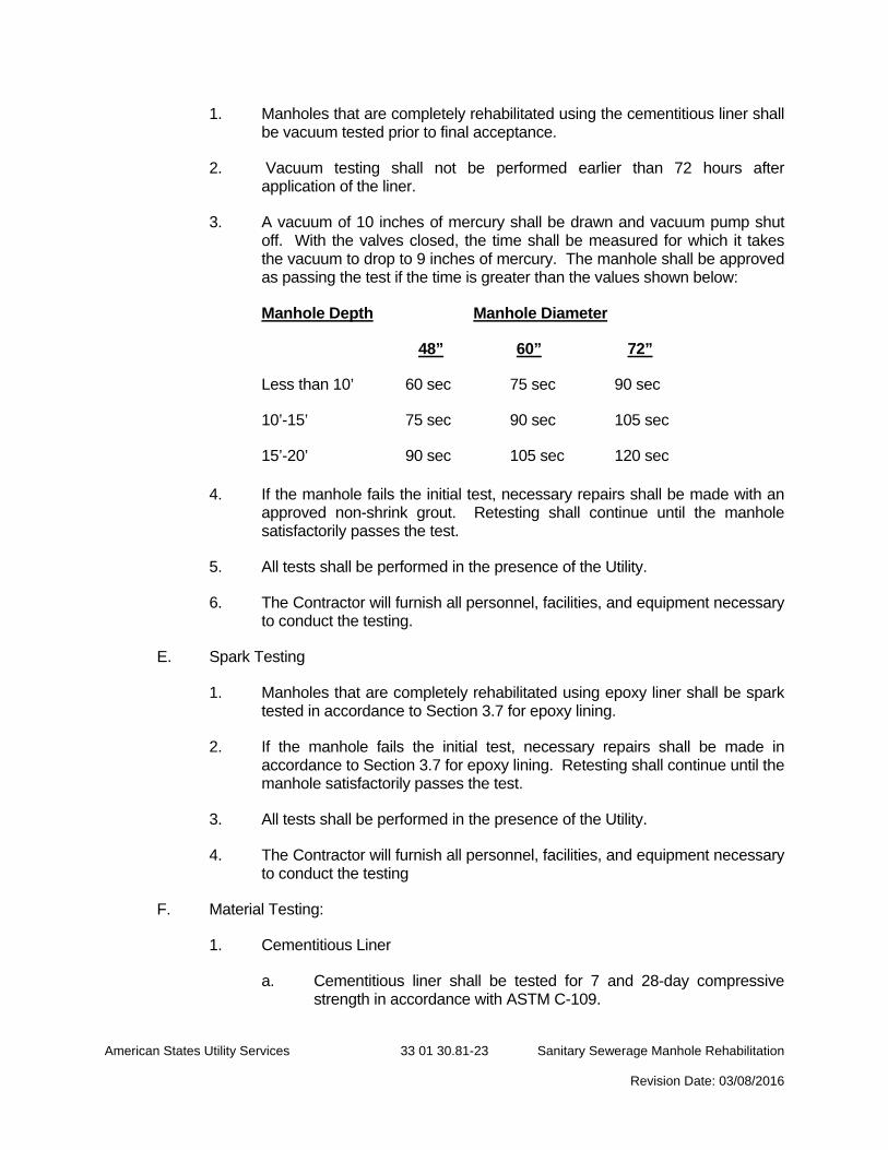
1. Manholes that are completely rehabilitated using the cementitious liner shall be vacuum tested prior to final acceptance.
2. Vacuum testing shall not be performed earlier than 72 hours after application of the liner.
3. A vacuum of 10 inches of mercury shall be drawn and vacuum pump shut off. With the valves closed, the time shall be measured for which it takes the vacuum to drop to 9 inches of mercury. The manhole shall be approved as passing the test if the time is greater than the values shown below:
Manhole Depth Manhole Diameter
48” 60” 72”
Less than 10’ 60 sec 75 sec 90 sec
10’-15’ 75 sec 90 sec 105 sec
15’-20’ 90 sec 105 sec 120 sec
4. If the manhole fails the initial test, necessary repairs shall be made with an approved non-shrink grout. Retesting shall continue until the manhole satisfactorily passes the test.
5. All tests shall be performed in the presence of the Utility.
6. The Contractor will furnish all personnel, facilities, and equipment necessary to conduct the testing.
E. Spark Testing
1. Manholes that are completely rehabilitated using epoxy liner shall be spark tested in accordance to Section 3.7 for epoxy lining.
2. If the manhole fails the initial test, necessary repairs shall be made in accordance to Section 3.7 for epoxy lining. Retesting shall continue until the manhole satisfactorily passes the test.
3. All tests shall be performed in the presence of the Utility.
4. The Contractor will furnish all personnel, facilities, and equipment necessary to conduct the testing
F. Material Testing:
1. Cementitious Liner
a. Cementitious liner shall be tested for 7 and 28-day compressive strength in accordance with ASTM C-109.
American States Utility Services 33 01 30.81-24 Sanitary Sewerage Manhole Rehabilitation Revision Date: 03/08/2016
b. Three samples shall be taken for every 50 bags of material used.
c. Samples shall be sprayed from the nozzle. Use three 3 by 6-inch diameter cylinders for testing.
d. Cylinders shall be labeled with date, project, manhole number, and product batch number.
e. Samples shall be sent to an independent testing agency for laboratory verification, results shall be provided to the Utility.
f. A written log shall be maintained referencing the specific bags of cement (product batch numbers) used per manhole, for all manholes.
2. Epoxy Liner
a. The Contractor shall produce samples of epoxy liner. These samples shall be spayed on concrete substrate (block), approx. 6 X 6-inch, approx. 60 mils thick, just prior to spraying the manholes.
b. Samples shall be labeled with the date, project, manhole number, and product batch number.
c. Samples shall be sent to an independent testing agency for laboratory verification, results shall be provided to the Utility.
3.20 CLEANUP
A. After the work has been completed and accepted by the Utility, the Contractor shall clean up the entire project area and return the ground cover to its original condition.
B. The Contractor shall dispose of all excess material and debris not incorporated into the permanent installation.
END OF SECTION 33 01 30.81