320680-C user manual - Affordable Security And Protection User Manuals/320680_0c_px_range... · PX...
52
PX Control Panel User Manual Issue C
-
Upload
truongdieu -
Category
Documents
-
view
219 -
download
0
Transcript of 320680-C user manual - Affordable Security And Protection User Manuals/320680_0c_px_range... · PX...

PX Control Panel
User Manual
Issue C

PX Control Panel User Manual – Issue C
- 2 -
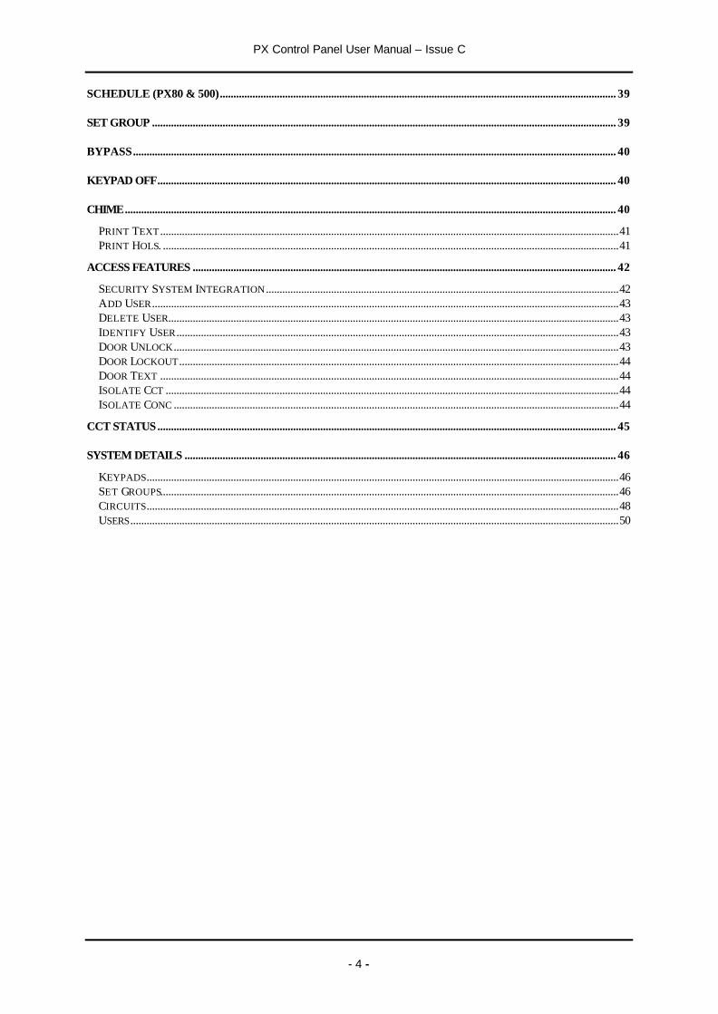
Contents
CONTENTS...............................................................................................................................................................................2
INTRODUCTION.....................................................................................................................................................................5
EVENT LOG.............................................................................................................................................................................5AREAS & SET GROUPS.........................................................................................................................................................5CIRCUITS................................................................................................................................................................................5USER, SET GROUP AND CIRCUIT IDENTIFICATION ........................................................................................................6USER CODES...........................................................................................................................................................................6
OPERATOR CONTROLS AND DISPLAYS ......................................................................................................................6
SYSTEM KEYPADS................................................................................................................................................................6Electronic Keys................................................................................................................................................................7Proximity Tokens.............................................................................................................................................................7
KEYSWITCH ...........................................................................................................................................................................7
USING THE SYSTEM..............................................................................................................................................................7
LOGGING ON...........................................................................................................................................................................7MENU FORMAT .....................................................................................................................................................................8
MENU LAYOUT........................................................................................................................................................................9
MENU LAYOUT..................................................................................................................................................................... 10
INVALID USER CODES.........................................................................................................................................................11USER ACCESS TIME.............................................................................................................................................................11ENGINEER ON SITE.............................................................................................................................................................11MENU RESTRICTIONS ........................................................................................................................................................11LOGGING OFF .......................................................................................................................................................................12HELP .....................................................................................................................................................................................13
Remote Service.............................................................................................................................................................. 13Contract ......................................................................................................................................................................... 13Product Info ................................................................................................................................................................... 13
KEYPAD BACKLIGHT .........................................................................................................................................................13LOG ON MESSAGES..............................................................................................................................................................13DUAL USER CODE OPERATION ........................................................................................................................................14
UNSET ..................................................................................................................................................................................... 14
UNSETTING METHODS ......................................................................................................................................................14Unsetting from a keypad ............................................................................................................................................. 14Unsetting from a keyswitch......................................................................................................................................... 16Automatic Unsetting .................................................................................................................................................... 16
UNSETTING WARNINGS.....................................................................................................................................................16UNSETTING AFTER AN ALARM .......................................................................................................................................16
SET........................................................................................................................................................................................... 17
SETTING FROM A KEYPAD................................................................................................................................................17KEYSWITCH SETTING........................................................................................................................................................17AUTOMATIC SETTING ......................................................................................................................................................18
Aborting The Setting Procedure................................................................................................................................ 18SETTING WITH WARNINGS...............................................................................................................................................18SETTING FAULTS................................................................................................................................................................18FAILURE TO SET AFTER EXIT TIME ...............................................................................................................................19
RESET...................................................................................................................................................................................... 20
CUSTOMER RESET ..............................................................................................................................................................20ENGINEER RESET ................................................................................................................................................................20

PX Control Panel User Manual – Issue C
- 3 -
MANAGED RESET ...............................................................................................................................................................20
TEST........................................................................................................................................................................................ 21
SOUNDER..............................................................................................................................................................................21STROBE .................................................................................................................................................................................21AUDIO...................................................................................................................................................................................21WALK TEST .........................................................................................................................................................................21COMMS TEST .......................................................................................................................................................................23
ENGINEER .............................................................................................................................................................................. 23
CODE....................................................................................................................................................................................... 23
USER........................................................................................................................................................................................ 24
NAME ....................................................................................................................................................................................24CODE .....................................................................................................................................................................................25AUTHORITY ........................................................................................................................................................................25CODE CHANGE.....................................................................................................................................................................26LOGON/SET ..........................................................................................................................................................................26SCHEDULE 1-2 (PX18/34)...................................................................................................................................................28SET GROUP 1-MAX .............................................................................................................................................................28DOOR 1-2 (PX18/34)............................................................................................................................................................28SCHEDULE (PX80/500) .......................................................................................................................................................28DOOR ACCESS (PX80/500)..................................................................................................................................................28
Challenged .................................................................................................................................................................... 28LOCKOUT (PX80/500).........................................................................................................................................................28EXPIRY DATE (PX80/500)..................................................................................................................................................28
LOGS ....................................................................................................................................................................................... 30
EVENT LOG MESSAGES.......................................................................................................................................................30PRINTED LOG.......................................................................................................................................................................30LOG-FULL .............................................................................................................................................................................31LOG-CCT ...............................................................................................................................................................................31LOG-USER.............................................................................................................................................................................31LOG-KP .................................................................................................................................................................................31LOG-DATE............................................................................................................................................................................31LOG-ALARM.........................................................................................................................................................................31A/LOG-FULL ........................................................................................................................................................................31A/LOG-USER.........................................................................................................................................................................31A/LOG-DOOR .......................................................................................................................................................................31LOG MESSAGES....................................................................................................................................................................32
TIME......................................................................................................................................................................................... 36
HOLIDAY................................................................................................................................................................................ 37
START ...................................................................................................................................................................................37END........................................................................................................................................................................................37SET GROUP (PX80/500) ......................................................................................................................................................37SET GROUP 1-8 (PX34) .......................................................................................................................................................37
SCHEDULE (PX18 & 34)..................................................................................................................................................... 38
SCHEDULE............................................................................................................................................................................. 38
START TIME ........................................................................................................................................................................38STOP TIME...........................................................................................................................................................................38MON-SUN .............................................................................................................................................................................38HOLIDAY ..............................................................................................................................................................................38
PX Control Panel User Manual – Issue C
- 4 -
SCHEDULE (PX80 & 500).................................................................................................................................................. 39
SET GROUP ........................................................................................................................................................................... 39
BYPASS.................................................................................................................................................................................. 40
KEYPAD OFF......................................................................................................................................................................... 40
CHIME..................................................................................................................................................................................... 40
PRINT TEXT .........................................................................................................................................................................41PRINT HOLS. ........................................................................................................................................................................41
ACCESS FEATURES ............................................................................................................................................................ 42
SECURITY SYSTEM INTEGRATION ..................................................................................................................................42ADD USER............................................................................................................................................................................43DELETE USER......................................................................................................................................................................43IDENTIFY USER...................................................................................................................................................................43DOOR UNLOCK ....................................................................................................................................................................43DOOR LOCKOUT ..................................................................................................................................................................44DOOR TEXT .........................................................................................................................................................................44ISOLATE CCT .......................................................................................................................................................................44ISOLATE CONC ....................................................................................................................................................................44
CCT STATUS......................................................................................................................................................................... 45
SYSTEM DETAILS ............................................................................................................................................................... 46
KEYPADS..............................................................................................................................................................................46SET GROUPS.........................................................................................................................................................................46CIRCUITS..............................................................................................................................................................................48USERS....................................................................................................................................................................................50

PX Control Panel User Manual – Issue C
- 5 -
Introduction
The PX Electronic Intruder Alarm System is designed to provide secure protection for the installation.The system is highly versatile, permitting individual systems to be installed and programmed to meet theparticular security requirements of each installation.
The system comprises a main control panel, normally located out of sight in a secure area, and at leastone keypad.
The panel has a wide range of features, which are programmed by the engineer on installation, to suitthe security requirements of the particular installation. Some of the features may be reprogrammed,edited, or viewed as required by an authorised user.
Event Log
The system incorporates an event log capable of recording the at least 250 events. The actual number ofevent stored is dependent on the panel type as shown in the table.
Feature PX18 PX34 PX80 PX500Security event log 250 250 500 1000Access Log 1000 1000 1000 1000
The event log will record all events, for example, user log-on times and user numbers, keypad numbers,setting and unsetting times, alterations made to programmed settings, fault conditions, etc. When theevent log is full, the oldest event will be automatically removed when the next event occurs.
All log events are date and time stamped and may be viewed, or printed if a printer is fitted to thesystem.
Areas & Set Groups
For protection purposes, the premises may be divided into a number of areas. Individual areas may begrouped together into a setting group which provides the user with a convenient way of setting andunsetting more than one area at the same time.
The installation company engineer will have configured your system for the appropriate number of areasand groups to comply with your specific security requirements.
Where more than one area is incorporated in the system, an area(s) can be configured by theinstallation engineer as a common area. A common area will automatically set if all other areas of thesystem are set and will automatically unset if any one of the other areas is unset.
Circuits
Each detector or sensor in the installation is allocated a unique circuit number. The installation engineerwill have programmed each circuit to respond in a certain way when the circuit is activated, when thearea is set and unset. The way in which the circuit is programmed to respond will depend on the type ofcircuit and its location and purpose.
If a circuit is faulty, the alarm response may be turned off by an authorised user. This process is referredto as bypassing.

PX Control Panel User Manual – Issue C
- 6 -
User, Set group and Circuit Identification
Each user, set group, and circuit can be programmed with a text description. An authorised user canchange a user text descriptor.
User Codes
Each user of the system is identified by a unique code. This code can be a PIN code, an electronic keyor proximity token. An electronic key can only be used on a keypad variant with an electronic keyinterface. A proximity token can only be used on a keypad variant with a proximity interface.
Throughout this manual user codes are only referred to as codes.
Operator Controls and Displays
System Keypads
2 x 16 characterLCD backlit display
Mains indicator
Optional electronickey socket
The operator keypad unit incorporates a backlit liquid crystal display (LCD) comprising 2 lines of 16characters, and a backlit keypad to gain access to the system and to perform all authorised userfunctions. Keypads may be fitted with an electronic key socket or an internal proximity reader. Thekeypad incorporates a mains power indicator. This indicator will flash if the system is operating onstandby battery power.
12:00 Mon 20 DecGuardall

PX Control Panel User Manual – Issue C
- 7 -
Electronic Keys
A user PIN code can be replaced by an electronic key. To use the facility at least one keypad in thesystem must have the optional electronic key interface fitted.
All Guardall electronic keys are manufactured with a unique code and duplicate keys cannot beobtained. Spare or replacement keys can be obtained from the installation company.
Proximity Tokens
A user PIN code can be replaced by a proximity token if the keypad is fitted with the optional proximityreader. There are 2 types of token available; a card or key fob.
All Guardall proximity tokens are manufactured with a unique code and duplicate tokens cannot beobtained. Spare or replacement tokens can be obtained from the installation company.
Keyswitch
As an alternative method of setting and unsetting, a simple On/Off keyswitch may be fitted to thesystem.
Using the System
When no user is logged on to a keypad, the time, date and company will normally be displayed.
12:00 Mon 27 SepGuardall
The LCD keypad will normally display the time, date and company name.
Logging on
A user logs on to the system by either:
1. Entering a user PIN code followed by 42. Inserting an electronic key3. Presenting a proximity token
The system will check that the entered user code is valid before permitting access to the system userfunctions.
12:00 Mon 27 SepEnter- ****
When a PIN code is entered the display will show an asterisk for eachdigit.
PX Control Panel User Manual – Issue C
- 8 -
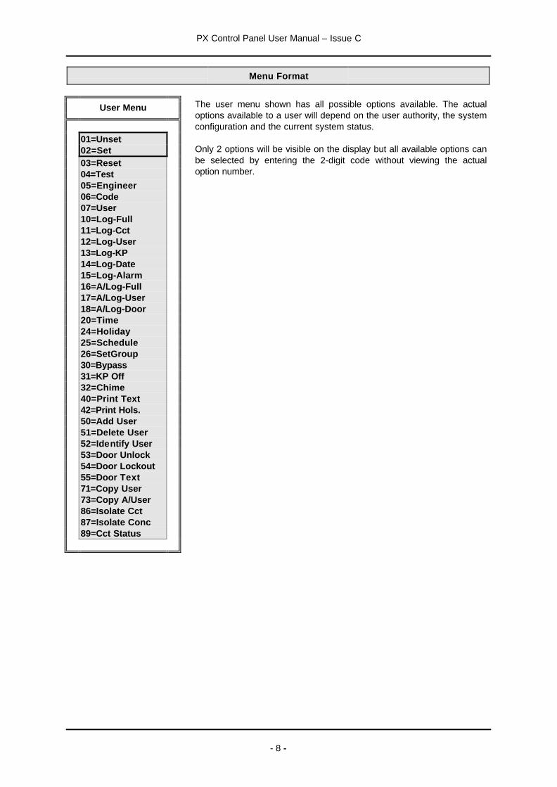
Menu Format
User Menu
01=Unset02=Set03=Reset04=Test05=Engineer06=Code07=User10=Log-Full11=Log-Cct12=Log-User13=Log-KP14=Log-Date15=Log-Alarm
The user menu shown has all possible options available. The actualoptions available to a user will depend on the user authority, the systemconfiguration and the current system status.
Only 2 options will be visible on the display but all available options canbe selected by entering the 2-digit code without viewing the actualoption number.
16=A/Log-Full17=A/Log-User18=A/Log-Door20=Time24=Holiday25=Schedule26=SetGroup30=Bypass31=KP Off32=Chime40=Print Text42=Print Hols.50=Add User51=Delete User52=Identify User53=Door Unlock54=Door Lockout55=Door Text71=Copy User73=Copy A/User86=Isolate Cct87=Isolate Conc89=Cct Status

PX Control Panel User Manual – Issue C
- 9 -
PX 18/34 Menu Layout
The menu map shows all possible menu options and, where appropriate, sub menus.
01=Unset02=Set03=Reset04=Test05=Engineer06=Code07=User10=Log-Full11=Log-Cct12=Log-User13=Log-KP14=Log-Date15=Log-Alarm16=A/Log Full17=A/Log User18=A/Log Door20=Time24=Holiday25=Schedule26=Set Group30=Bypass31=KP Off32=Chime40=Print Text42=Print Hols.50=Add User51=Delete User52=Identify User53=Door Unlock54=Door Lockout55=Door Text71=Copy User73=Copy A/User86=Isolate Cct87=Isolate Conc89=Cct Status
1=Group 12=Group 2. . .8=Group 8
AreaNumber-?
UserNumber- _ _
1=Display2=Print
EngineerGuardall
CircuitNumber-__
Time00:00
HolidayNumber-__
CircuitNumber-__
01 04 05
30, 322420
02
1=Sounder2=Audio3=Strobe4=Walk Test5=Comms Test
1=Silent Set2=Instant Set
?
07
New CodeEnter-
06
11
UserNumber-__
12, 1710, 15, 16
KeypadNumber-_
13
Filter DateEnterDDMMYYYY
14
Holiday 1Start-OffEnd-OffSet Group-00
KeypadNumber-_
31
PrintingText
PrintingHoliday
4240
ScheduleNumber-__
25
Schedule-nStart Time- 00:00Stop Time- 00:00Mon-OffTue-OffWed-OffThu-OffFri-OffSat-OffSun-OffHoliday-Off
User-xx"Descriptor"ManagerCode Change-OnLogOn/Set-OnSchedule 1-0Schedule 2-0Group 1-OffGroup 2-Off. . .Group 8-OffDoor 1-OffDoor 2-Off
3
1=Group 12=Group 2. . .8=Group 8
1=Name2=Code3=Authority
DoorNumber-__
18
User nPresent Card/Fob
Delete Users___-___
Present Card/Fob
50 51 52
DoorNumber-_
53, 54, 55
Copy User ____-__
Copy A/User ________-____
71 73
ConcentratorNumber-_
87
CircuitNumber-__
86
Set GroupNumber-__
26
PX Control Panel User Manual – Issue C
- 10 -
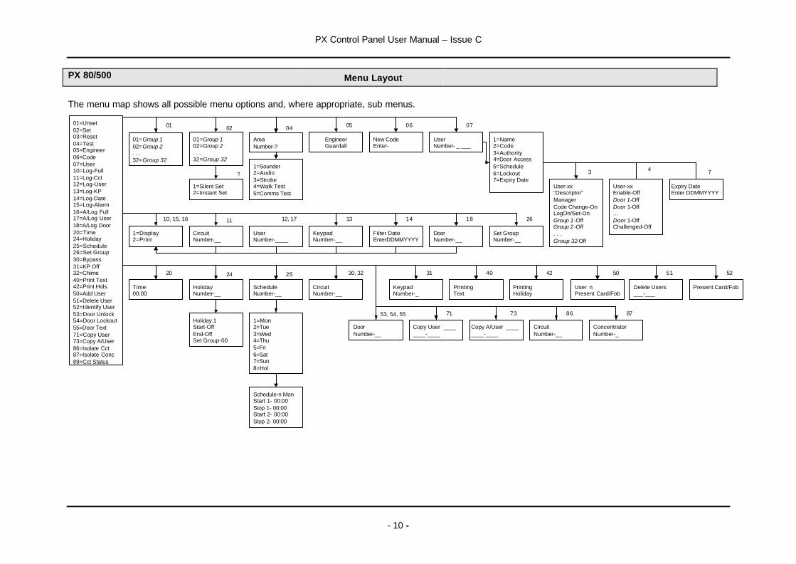
PX 80/500 Menu Layout
The menu map shows all possible menu options and, where appropriate, sub menus.
01=Unset02=Set03=Reset04=Test05=Engineer06=Code07=User10=Log-Full11=Log-Cct12=Log-User13=Log-KP14=Log-Date15=Log-Alarm16=A/Log Full17=A/Log User18=A/Log Door20=Time24=Holiday25=Schedule26=Set Group30=Bypass31=KP Off32=Chime40=Print Text42=Print Hols.50=Add User51=Delete User52=Identify User53=Door Unlock54=Door Lockout55=Door Text71=Copy User73=Copy A/User86=Isolate Cct87=Isolate Conc89=Cct Status
01=Group 102=Group 2. . .32=Group 32
AreaNumber-?
UserNumber- _ ___
1=Display2=Print
EngineerGuardall
CircuitNumber-__
Time00:00
HolidayNumber-__
CircuitNumber-__
01 04 05
30, 322420
02
1=Sounder2=Audio3=Strobe4=Walk Test5=Comms Test
1=Silent Set2=Instant Set
?
07
New CodeEnter-
06
11
UserNumber-____
12, 1710, 15, 16
KeypadNumber-__
13
Filter DateEnterDDMMYYYY
14
Holiday 1Start-OffEnd-OffSet Group-00
KeypadNumber-_
31
PrintingText
PrintingHoliday
4240
ScheduleNumber-__
25
User-xx"Descriptor"ManagerCode Change-OnLogOn/Set-OnGroup 1 -OffGroup 2 -Off. . .Group 32-Off
3
1=Mon2=Tue3=Wed4=Thu5=Fri6=Sat7=Sun8=Hol
Schedule-n MonStart 1- 00:00Stop 1- 00:00Start 2- 00:00Stop 2- 00:00
01=Group 102=Group 2. . .32=Group 32
1=Name2=Code3=Authority4=Door Access5=Schedule6=Lockout7=Expiry Date
User-xxEnable-OffDoor 1-OffDoor 1-Off...Door 1-OffChallenged-Off
4
Expiry DateEnter DDMMYYYY
7
DoorNumber-__
18
User nPresent Card/Fob
Delete Users___-___
Present Card/Fob
50 51 52
DoorNumber-__
53, 54, 55
Copy User ________-____
Copy A/User ________-____
71 73
ConcentratorNumber-_
87
CircuitNumber-__
86
Set GroupNumber-__
26
PX Control Panel User Manual – Issue C
- 11 -
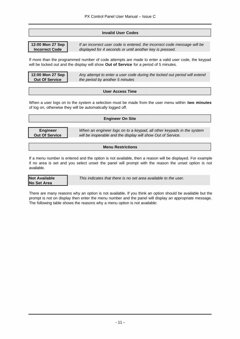
Invalid User Codes
12:00 Mon 27 SepIncorrect Code
If an incorrect user code is entered, the incorrect code message will bedisplayed for 4 seconds or until another key is pressed.
If more than the programmed number of code attempts are made to enter a valid user code, the keypadwill be locked out and the display will show Out of Service for a period of 5 minutes.
12:00 Mon 27 SepOut Of Service
Any attempt to enter a user code during the locked out period will extendthe period by another 5 minutes
User Access Time
When a user logs on to the system a selection must be made from the user menu within two minutesof log on, otherwise they will be automatically logged off.
Engineer On Site
EngineerOut Of Service
When an engineer logs on to a keypad, all other keypads in the systemwill be inoperable and the display will show Out of Service.
Menu Restrictions
If a menu number is entered and the option is not available, then a reason will be displayed. For exampleif no area is set and you select unset the panel will prompt with the reason the unset option is notavailable.
Not AvailableNo Set Area
This indicates that there is no set area available to the user.
There are many reasons why an option is not available. If you think an option should be available but theprompt is not on display then enter the menu number and the panel will display an appropriate message.The following table shows the reasons why a menu option is not available:
PX Control Panel User Manual – Issue C
- 12 -
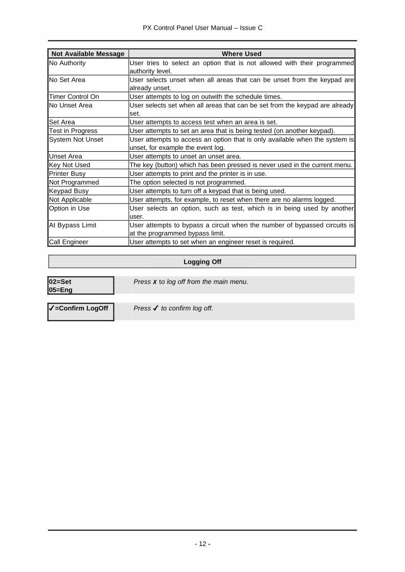
Not Available Message Where UsedNo Authority User tries to select an option that is not allowed with their programmed
authority level.No Set Area User selects unset when all areas that can be unset from the keypad are
already unset.Timer Control On User attempts to log on outwith the schedule times.No Unset Area User selects set when all areas that can be set from the keypad are already
set.Set Area User attempts to access test when an area is set.Test in Progress User attempts to set an area that is being tested (on another keypad).System Not Unset User attempts to access an option that is only available when the system is
unset, for example the event log.Unset Area User attempts to unset an unset area.Key Not Used The key (button) which has been pressed is never used in the current menu.Printer Busy User attempts to print and the printer is in use.Not Programmed The option selected is not programmed.Keypad Busy User attempts to turn off a keypad that is being used.Not Applicable User attempts, for example, to reset when there are no alarms logged.Option in Use User selects an option, such as test, which is in being used by another
user.At Bypass Limit User attempts to bypass a circuit when the number of bypassed circuits is
at the programmed bypass limit.Call Engineer User attempts to set when an engineer reset is required.
Logging Off
02=Set05=Eng
Press 7to log off from the main menu.
4=Confirm LogOff Press 4 to confirm log off.

PX Control Panel User Manual – Issue C
- 13 -
Help
The system will display context sensitive help for menu and programming options. When the main menuis on display press the help button (?) to display information about the system.
02=Set The normal log on menu05=Eng
Press the ? button to display the customer help menu.
Help Menu
0=Remote Service1=Contract2=Product Info
Help Menu Remote Service
The remote service option is only required if your alarm company offers this service. Before using theremote service option you must obtain a number from your alarm company. When you need to use theremote service, you will be prompted to enter this number, and the panel will dial the alarm company.The alarm company will then be able to check the condition of your system and identify and resolveproblems.
Help Menu Contract
The contract number uniquely identifies the system.
Contract123456
The customer contract number is a 6-digit number programmed by theinstallation engineer.
Help Menu Product Info
W73797 v1.00 The panel order code and firmware version numberS.Dial v4.0x The SmartDial version number (if fitted)
Press the quit button (7) to return to the normal menu.
Keypad Backlight
The LCD keypad incorporates backlighting. The backlighting will be turned on during the entry time,during code entry and while a user is logged on. It may also be turned on using any button except 4and 7and turned off using the 4 or 7 buttons.
Log On Messages
When a user logs on, the system may display a special message(s) before the normal menu isdisplayed. The special messages include:

PX Control Panel User Manual – Issue C
- 14 -
Message ReasonAlarm Abort User logs on within the alarm abort period (programmable option)Setting Stopped User logs on during the setting exit periodGroup Unset A group(s) is set and is programmed to automatically unset when a user logs on.Cannot Set The system cannot set, the reason(s) will then be displayed.Unset Alarm An unset alarm has occurred, the details will then be displayed.Mult.Alarm A circuit(s) has alarmed the maximum number of times allowed (programmable).
The circuit details will then be displayed.Code Known Another user has chosen your code. You will then be given the option of
immediately changing your code. This message will always be displayed on logon until the code is changed.
Call Engineer You should call the installation company. The details will then be displayed.Reset OK A managed reset code has been acceptedSet4=Confirm
The user is configured for the log on set option. If confirmed the system will startsetting (if only one group is authorised) or display the set group menu.
Soak Cct Fails Circuits which have been put on special test by the installation engineer havealarmed.
Dual User Code Operation
Where a higher level of security is required a keypad may have been programmed to require two usercodes to be entered before logging a user on to the system. Both user codes must be authorised andare logged by the system. The authority of the second user code entered is used by the system.
Unset Code-01
The system will have been partitioned by the installation engineer into a number of set groups. The userauthority will determine the choice of groups, which can be unset. There are several methods ofunsetting available to the user. These methods are discussed in the following section.
Unsetting Methods
If a set group incorporates an entry route in the unsetting procedure then opening a final entry door tothe area will start a pre-programmed entry timer. The user must proceed directly to the keypad orkeyswitch via a pre-determined entry route and unset the group as described.
If the group is not unset before the entry time has expired a warning period, equivalent to 50% of theprogrammed entry time, will be allowed. This is to warn the user that an alarm condition will occur if thegroup is not unset by the end of the warning period. If the group is not unset by the time that the totalentry time and warning time has expired, an alarm condition will be initiated.
During the entry time, if a user deviates from the prescribed entry route into an armed area, the entrytime is immediately cancelled. If programmed, a fixed pre-warning period of 45 seconds will be given,otherwise an immediate alarm will be given. If the user enters an armed area during the entry warningperiod, the warning period is cancelled and an immediate alarm will be given.
Unsetting from a keypad
To unset, log on to the keypad. If an authorised group is configured for automatic logon/unset then theunset group descriptor will be displayed.
WorkshopUnset
If more than 1 group is configured for logon/unset then only the firstdescriptor will be displayed.

PX Control Panel User Manual – Issue C
- 15 -
If automatic logon/unset is not configured then choose the unset option manually.
PX Control Panel User Manual – Issue C
- 16 -
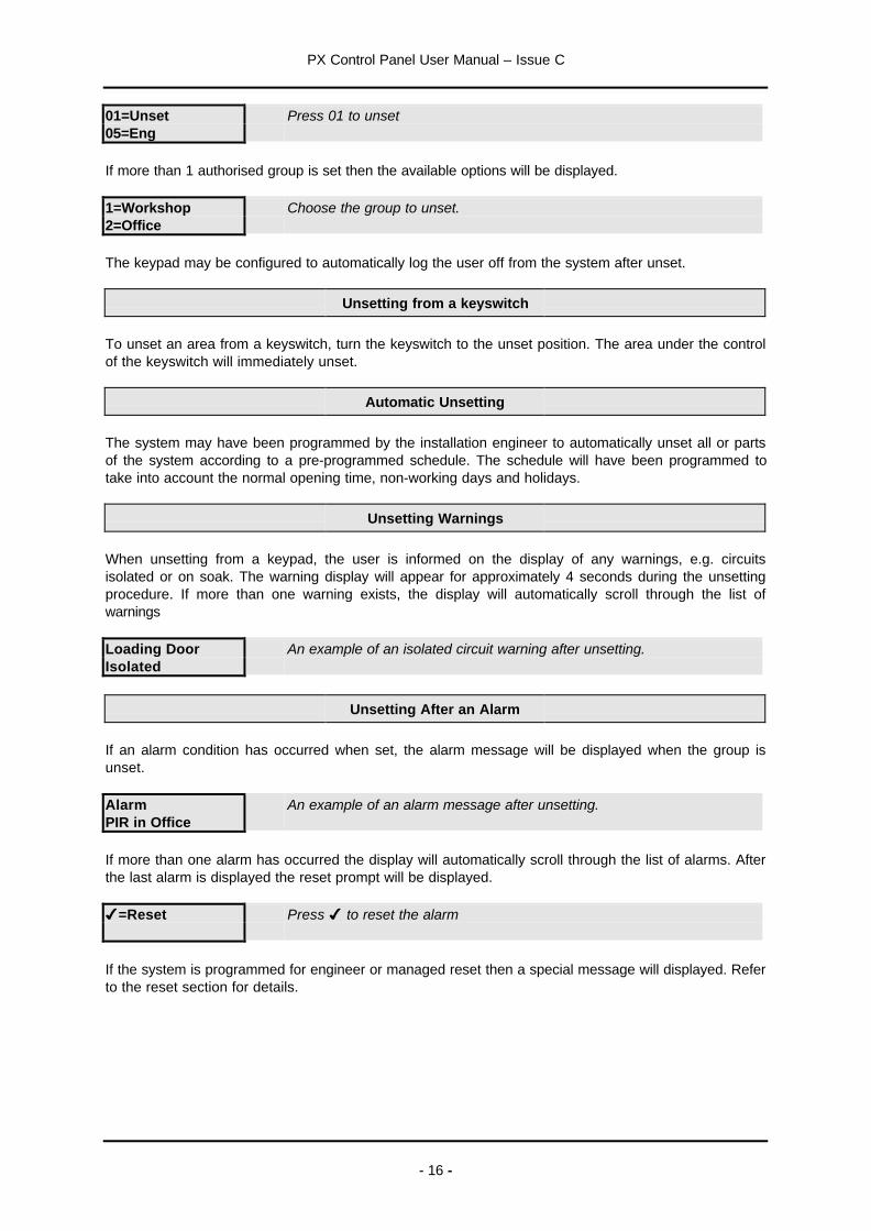
01=Unset05=Eng
Press 01 to unset
If more than 1 authorised group is set then the available options will be displayed.
1=Workshop2=Office
Choose the group to unset.
The keypad may be configured to automatically log the user off from the system after unset.
Unsetting from a keyswitch
To unset an area from a keyswitch, turn the keyswitch to the unset position. The area under the controlof the keyswitch will immediately unset.
Automatic Unsetting
The system may have been programmed by the installation engineer to automatically unset all or partsof the system according to a pre-programmed schedule. The schedule will have been programmed totake into account the normal opening time, non-working days and holidays.
Unsetting Warnings
When unsetting from a keypad, the user is informed on the display of any warnings, e.g. circuitsisolated or on soak. The warning display will appear for approximately 4 seconds during the unsettingprocedure. If more than one warning exists, the display will automatically scroll through the list ofwarnings
Loading DoorIsolated
An example of an isolated circuit warning after unsetting.
Unsetting After an Alarm
If an alarm condition has occurred when set, the alarm message will be displayed when the group isunset.
AlarmPIR in Office
An example of an alarm message after unsetting.
If more than one alarm has occurred the display will automatically scroll through the list of alarms. Afterthe last alarm is displayed the reset prompt will be displayed.
4=Reset Press 4 to reset the alarm
If the system is programmed for engineer or managed reset then a special message will displayed. Referto the reset section for details.
PX Control Panel User Manual – Issue C
- 17 -
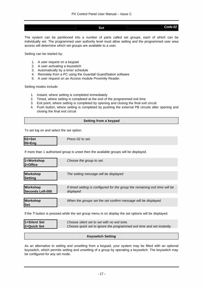
Set Code-02
The system can be partitioned into a number of parts called set groups, each of which can beindividually set. The programmed user authority level must allow setting and the programmed user areaaccess will determine which set groups are available to a user.
Setting can be started by:
1. A user request on a keypad2. A user activating a keyswitch3. Automatically by a timer schedule4. Remotely from a PC using the Guardall GuardStation software5. A user request on an Access module Proximity Reader.
Setting modes include:
1. Instant, where setting is completed immediately2. Timed, where setting is completed at the end of the programmed exit time3. Exit point, where setting is completed by opening and closing the final exit circuit4. Push button, where setting is completed by pushing the external PB circuits after opening and
closing the final exit circuit
Setting from a keypad
To set log on and select the set option.
02=Set05=Eng
Press 02 to set.
If more than 1 authorised group is unset then the available groups will be displayed.
1=Workshop2=Office
Choose the group to set.
WorkshopSetting
The setting message will be displayed
WorkshopSeconds Left-005
If timed setting is configured for the group the remaining exit time will bedisplayed
WorkshopSet
When the groups set the set confirm message will be displayed.
If the ? button is pressed while the set group menu is on display the set options will be displayed.
1=Silent Set2=Quick Set
Choose silent set to set with no exit tone.Choose quick set to ignore the programmed exit time and set instantly.
Keyswitch Setting
As an alternative to setting and unsetting from a keypad, your system may be fitted with an optionalkeyswitch, which permits setting and unsetting of a group by operating a keyswitch. The keyswitch maybe configured for any set mode.

PX Control Panel User Manual – Issue C
- 18 -
Automatic Setting
The system may have been programmed by the installation engineer to automatically set all or parts ofthe system according to a pre-programmed schedule. The schedule will have been programmed to takeinto account the normal closing time, non-working days and holidays. The schedule may be configuredfor any set mode.
Aborting The Setting Procedure
The setting procedure can be aborted at any time during the exit time by pressing 7on the keypad thatwas used to start setting, logging on to any other keypad or turning a keyswitch to the unset position.
SettingStopped
If setting is aborted by logging onto a keypad the setting aborted messagewill be displayed.
Setting with Warnings
The system will automatically display any conditions which the user should be aware of before settingthe system. These conditions are described as set warnings and do not prohibit the user from settingthe system in the normal way. The user however may wish to change a condition before setting thearea(s) or system, where appropriate.
When a user selects set, and warnings exist, the set warning prompt will be displayed.
Set Warning4=Report Press the 4 button to display the setting warning(s).
Loading DoorIsolated
The display will automatically scroll through the list of warnings
Workshop4=Set Press 4 to proceed with setting or press 7 to cancel setting
The set warnings include:
1. Bypassed circuits2. Circuits On Soak (a special circuit test mode set up by the installation engineer)3. Isolated circuits4. Line Fault (only when setting with telephone line fault is allowed)
Setting Faults
The system will not permit setting with faults or with any circuit open or activated, with the exception ofexit route circuits or circuits which have been bypassed or isolated.
When a user selects set, and faults exist, the set warning prompt will be displayed.
Cannot Set
TamperRear Door
The display will automatically scroll through the list of faults
The system may have been programmed to allow the user to force set if circuit faults exist.

PX Control Panel User Manual – Issue C
- 19 -
4=Force Set Press the 4 button to try to force set.
If the circuits in fault can be bypassed then the system will report the bypassed circuits and then promptthe user to confirm setting.
Failure to Set after Exit Time
If the group fails to set at the end of the exit period, the exit tone will change to warn the user that thesystem has not set. Log on to the keypad to display the fault condition(s). The external sounder mayalso have been programmed by the installation engineer to activate in the event of a failure to set.

PX Control Panel User Manual – Issue C
- 20 -
Reset Code-03
The resetting method programmed by the alarm company engineer for each area and the system willdepend on the particular security requirements of the area or system. There are 3 types of reset:
1. Customer reset, where the customer can reset any alarm2. Engineer reset, where the alarm company engineer must reset all alarms3. Managed reset, where the customer can reset an alarm after reporting the event to the alarm
company
Customer Reset
If an alarm condition has occurred when set, the alarm message will be displayed when the group isunset.
AlarmPIR in Office
An example of an alarm message after unsetting.
If more than one alarm has occurred the display will automatically scroll through the list of alarms. Afterthe last alarm is displayed the reset prompt will be displayed.
4=Reset Press 4 to reset the alarm
If an alarm condition cannot be reset then a message will be displayed.
Engineer Reset
If the system is configured for engineer reset then after the alarm(s) information is displayed a specialprompt will be displayed.
01313333802Code:123456
The number to call for a service engineerQuote your customer contract number
When an engineer reset is required, it will not be possible to set the system until an engineer has beento the site.
Managed Reset
If the system is configured for managed reset then after the alarm(s) information is displayed a specialprompt will be displayed. This feature operates in a similar way to engineer reset. After the call engineerprompt the telephone and code numbers will be displayed.
01313333802Code:12345
The number to call for a service engineerQuote your code number
The alarm company will issue a special 5-digit PIN code. This PIN code can be used only once to resetthe system.
Reset OK Log on using the 5 digit reset code. If the code is accepted this messagewill be displayed.

PX Control Panel User Manual – Issue C
- 21 -
Test Code-04
Each area of the system can be tested individually or all areas can be tested at the same time. The testtime is limited to 1 hour. If the user does not end the test by the end of the test time then the panel willexit test mode automatically. When the test option is selected the area test menu will be displayed.
Test Areas Menu
AreaNumber-?
Enter the area number to test (area 0 for the system).
When an area(s) is selected the test options menu will be displayed.
Test Options Menu
1=Sounder2=Strobe3=Audio4=Walk Test5=Comms Test
Choose the item that you want to test from the test menu.
Test Options Sounder Code-1
The external sounder(s) will be turned on until the user presses the 7button.
Test Options Strobe Code-2
The external strobe(s) will be turned on until the user presses the 7button.
Test Options Audio Code-3
The internal sounder(s) will be turned on until the user presses the 7button.
Test Options Walk Test Code-4
The panel records all activations from sensors during the unset period. When walk test is selected thepanel will display all circuits which have not alarmed since the panel was last unset. If all circuits are tobe tested then select walk test, then press the 7button and select walk test a second time.
When walk test is selected the keypad will automatically scroll through the list of circuits which have notbeen tested.
Hall PIRNot Tested
All circuits still to be tested will be displayed.
When all circuits have responded then “All Tested” message will be displayed and the panel will exit walktest:
Walk Test

PX Control Panel User Manual – Issue C
- 22 -
All Tested

PX Control Panel User Manual – Issue C
- 23 -
When the panel exits test mode, either manually or automatically at the end of the test time then:
1. Any fire sensor still in alarm will give a normal alarm response.2. Circuits with a 24-hour response, which are still in alarm, will be temporarily bypassed.3. A warning will be displayed if any PA sensor is still in alarm.
Test Options Comms Test Code-5
If the comms test is selected then the panel will make a test call to all telephone numbers that havebeen programmed for test by the installation engineer.
Engineer Code-05
The Eng option will only be available if the system is configured for user authorised engineer access. Thisoption applies to both local and remote engineer access.
When the Eng option is selected the system will prompt for the engineer PIN code to be entered.
EngineerGuardall
The engineer must log on within 2 minutes.Press 7to cancel the engineer log on authorisation.
Once logged on the engineer working time is limited to 8 hours.
Code Code-06
All users on the system are identified by a user code. A user code can be a PIN code, an electronic keyor proximity token. To change user code, log on to the keypad using your current code and choose thecode option. Then follow the display prompts. All user code changes are recorded in the system eventlog.
Note: If the code option is not available this means that the system has been programmed to preventyou from changing your user code, and a new code must be allocated by the security system manager.
New CodeEnter-
The chosen code may be any unique 4, 5 or 6 digit code.
If the entered code is not available the a warning message will be displayed.
New CodeNot Available
Re-enter CodeEnter-
The new code must be re-entered before being accepted by the system
New CodeDoes not Match
If the re-entered code does not match a message will be displayed and thesystem will prompt again for a new code.
New CodeNot Available
If the new code is not available you must choose another new code.
If a suitable keypad is used then the user code may be changed to either an electronic key or proximitytoken. If you are changing code to an electronic key then insert the key when the system prompts for acode. If you are changing code to a proximity token then present the token when the system prompts fora code. When using a proximity token you will not be prompted to re-enter the code.

PX Control Panel User Manual – Issue C
- 24 -
User Code-07
Feature PX18 PX34 PX80 PX500Max. Users 20 40 1000 1000Max. Security 20 40 100 200
A manager user can change the name, user code and authority for any user except the engineer. Tomodify a user’s details enter the user number in the range 2-max users. The user menu will then bedisplayed.
The user 2 configuration may only be changed by user 1 or user.
Access system users be added quickly using the “Add User” menu option (50).
User Menu
1=Name2=Code3=Authority4=Door Access5=Schedule6=Lockout7=Expiry Date
Choose the required option.
This option is not available on the PX18/34.This option is not available on the PX18/34.This option is not available on the PX18/34.This option is not available on the PX18/34.
User Name Code-1
When the name option is selected the current user descriptor will be displayed. Names can be up to 10characters long and may contain any of the following characters.
ABCDEFGHIJKLMNOPQRSTUVWXYZabcdefghijklmnopqrstuvwxyz .-/+#%^&*@<>:!$?_0123456789
By default all names are “User” followed by the user number, for example User 2.
User Number-03J Smith The first character of the text descriptor will be flashing.
When you edit a name the first letter will be flashing. You can either use the é or ê buttons to selectthe required character or use one of the numeric keys to quickly access a particular character.
Fast character access buttonsButton 1 2 3 4 5 6 7 8 9
Character A M Z a m z 1 9 space
Use the 4 button to move to the next character position on the right. Press 7to save the descriptor andexit. To clear all characters to the right of the cursor press 0.

PX Control Panel User Manual – Issue C
- 25 -
User Menu Code Code-2
For details of changing a code refer to the section on code change on page 23.
The default user codes are shown in the table.
Default CodesUser Number PIN
2 02023-last user Off
User Menu Authority Code-3
Users can be programmed with a number or options including authority level, area access and timedaccess.
When the authority option is selected the user authority menu is displayed.
User Options
User-nnnn nnnn=User numberUser NameManager Press ? for list of user authoritiesCode Change-On On/OffLogOn/Set-On On/OffSchedule 1-Off On/Off (PX18/34 only)Schedule 2-Off On/Off (PX18/34 only)Group 1-Off On/OffGroup 2-Off On/Off…Group 32-Off On/Off, the number of groups depends on the panel type
On/Off (PX18/34 only)Door 1-OffDoor 2-Off On/Off (PX18/34 only)
The available menu options are dependent on the programmed user authority.
User Auth Help
0=Off1=Manager2=Ordinary3=Set/Uns4=Set5=Unset6=Cleaner7=Access8=Reset9=Duress
Refer to the user authority option table for full details of options availablefor each user type.

PX Control Panel User Manual – Issue C
- 26 -
The menu options available to each authority level are shown in the table.
Menu Option User Authority LevelCode Text Man Ord Set/
UnsSet Unset Cleaner Access Reset Duress
01 Unset 3 3 3 7 3 3 7 7 3
02 Set 3 3 3 3 7 3 7 7 7
03 Reset 3 3 3 7 7 7 7 3 3
04 Test 3 3 7 7 7 7 7 7 7
05 Engineer 1 1 1 1 7 7 7 7 7
06 Code 3 2 2 2 7 7 7 7 207 User 3 7 7 7 7 7 7 7 7
10 Log-Full 3 7 7 7 7 7 7 7 7
11 Log-Cct 3 7 7 7 7 7 7 7 7
12 Log-User 3 7 7 7 7 7 7 7 7
13 Log-KP 3 7 7 7 7 7 7 7 7
14 Log-Date 3 7 7 7 7 7 7 7 7
15 Log-Alarm 3 7 7 7 7 7 7 7 7
16 A/Log-Full 3 7 7 7 7 7 7 7 7
17 A/Log-User 3 7 7 7 7 7 7 7 7
18 A/Log-Door 3 7 7 7 7 7 7 7 7
20 Time +/-75m 3 3 7 7 7 7 7 7 7
24 Holiday 3 7 7 7 7 7 7 7 7
25 Schedule 3 7 7 7 7 7 7 7 7
26 Set Group 3 7 7 7 7 7 7 7 7
30 Bypass 4 4 7 7 7 7 7 7 7
31 KP Off 3 7 7 7 7 7 7 7 7
32 Chime 3 3 7 7 7 7 7 7 7
40 Print Text 3 7 7 7 7 7 7 7 7
42 Print Hols. 3 7 7 7 7 7 7 7 7
50 Add User 3 7 7 7 7 7 7 7 7
51 Delete User 3 7 7 7 7 7 7 7 7
52 IdentifyUser 3 7 7 7 7 7 7 7 7
53 Door Unlock 3 7 7 7 7 7 7 7 7
54 Door Lockout 3 7 7 7 7 7 7 7 7
55 Door Text 3 7 7 7 7 7 7 7 7
71 Copy User 3 7 7 7 7 7 7 7 7
73 Copy A/User 3 7 7 7 7 7 7 7 7
86 Isolate Cct 5 7 7 7 7 7 7 7 7
87 Isolate Conc 5 7 7 7 7 7 7 7 7
89 Cct Status 3 7 7 7 7 7 7 7 7
Notes: Items marked 1-5 will only be available if programmed by the installation engineer.
User Authority Menu Code Change On/Off
Some user types are allowed by default to change their own code (refer to authority table). This featurecan be disabled for any user without manager authority.
User Authority Menu LogOn/Set On/Off
If this option is on, a set prompt will be displayed in place of the normal log on menu, when the user logson. If the user has only the set option available then either a list of the groups, which can be set, will be

PX Control Panel User Manual – Issue C
- 27 -
displayed when logging on or, if there is only one set group available, setting will start when the userlogs on.
PX Control Panel User Manual – Issue C
- 28 -
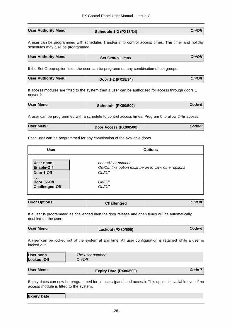
User Authority Menu Schedule 1-2 (PX18/34) On/Off
A user can be programmed with schedules 1 and/or 2 to control access times. The timer and holidayschedules may also be programmed.
User Authority Menu Set Group 1-max On/Off
If the Set Group option is on the user can be programmed any combination of set groups.
User Authority Menu Door 1-2 (PX18/34) On/Off
If access modules are fitted to the system then a user can be authorised for access through doors 1and/or 2.
User Menu Schedule (PX80/500) Code-5
A user can be programmed with a schedule to control access times. Program 0 to allow 24hr access.
User Menu Door Access (PX80/500) Code-5
Each user can be programmed for any combination of the available doors.
User Options
User-nnnn nnnn=User numberEnable-Off On/Off, this option must be on to view other optionsDoor 1-Off On/Off. . .Door 32-Off On/OffChallenged-Off On/Off
Door Options Challenged On/Off
If a user is programmed as challenged then the door release and open times will be automaticallydoubled for the user.
User Menu Lockout (PX80/500) Code-6
A user can be locked out of the system at any time. All user configuration is retained while a user islocked out.
User-nnnn The user numberLockout-Off On/Off
User Menu Expiry Date (PX80/500) Code-7
Expiry dates can now be programmed for all users (panel and access). This option is available even if noaccess module is fitted to the system.
Expiry Date

PX Control Panel User Manual – Issue C
- 29 -
Off No expiry date is programmed, press enter to change

PX Control Panel User Manual – Issue C
- 30 -
Expiry DateEnter DDMMYYYY Enter the day, month and year.
To delete an expiry date enter the day and month of 0000 and the current year.
Logs
The panel logs all events that occur in the system. All events stored in the event log are numbered in therange 0-65535. The event number is only used when printing the log. The event number will be the sameeven if the event is printed as part of a filtered log. The event number will only be reset if more than65535 events have been recorded.
The event log may be displayed or printed in full or in filtered form. Printing will only be available if aprinter interface is fitted to the system. When a log option is selected the display or print choice menuwill be displayed.
1=Display2=Print
Press 1 to display or 2 to print the selected log items.The print option will only be available if a printer is fitted to the system
Logs Event Log Messages
Log messages are constructed using the event time, the event type and the additional informationspecified by the event type. Each event is time stamped to the nearest 2 seconds. If a text descriptionhas been programmed it will be used in the printed log. When the log is displayed abbreviations areused.
The displayed log format is:
PIR in Hall the circuit description Bypassed the event type
The event time and circuit number may be displayed in place of the normal top line information bypressing the ? button.
12:00:00 Cct 1 the event time and additional data Bypassed the event type
Press the ? button again to display the user number.
U xxxx Cct 1 the event time and additional data Bypassed the event type
You can set the display mode you prefer or use the ? button to switch between display modes as youscroll through the logged events. You can use the é and ê buttons to step through the events.
In the table below all messages logged by the panel are shown. Some message types are stored in boththe alarm and event logs and some are stored in the event log only.
Logs Printed Log
If the log is printed then the log index number, text descriptors and the date will be printed for each event.
00001 Sat 02 Jan 00:00:02 User 2 (Mr Smith) Logged On on KP 0

PX Control Panel User Manual – Issue C
- 31 -
Logs Log-Full Code-10
All logged events may be displayed or printed.
Logs Log-Cct Code-11
All logged events for a particular circuit number may be displayed or printed.
Logs Log-User Code-12
All logged events for a particular user may be displayed or printed.
Logs Log-KP Code-13
All logged events for a particular keypad may be displayed or printed.
Logs Log-Date Code-14
All logged events for a particular date may be displayed or printed.
Logs Log-Alarm Code-15
All logged alarm events may be displayed or printed.
Access Log A/Log-Full Code-16
The access log capacity of the system is 1000 events. This log contains the most recent 1000 eventsfor all doors in chronological order. All log options are configurable for each door. The Access log optionsare only accessible to users with manager authority.
The full access log may be displayed or printed.
Access Log A/Log-User Code-17
Events for a single access user may be displayed or printed. Select option 17, then enter the usernumber.
Access Log A/Log-Door Code-18
Events for a single door may be displayed or printed. Select option 18, then enter the door number.

PX Control Panel User Manual – Issue C
- 32 -
Logs Log Messages
Alarm & Event Log messagesLog Text Additional Data Display Text Event Description
Alarm Circuit nnn Cctnnn A Circuit alarmAnti mask Circuit nnn Cctnnn A Circuit program with the anti-
mask option has alarmedBat.Monitor Fail NONE (see note) NONE Battery voltage is low or not
present during a battery testBattery Low NONE (see note) NONE The battery has reached the low
volts threshold (after a mains fail)Comm Fail NONE NONE Control panel comm fail input
active.Entry Alarm Area n An The area is not unset before the
end of the entry warning periodFire Circuit nnn Cctnnn A fire type circuit alarmPanel Tamper NONE NONE Panel case or off the
wall tamperPersonal Attack Circuit nnn Cctnnn A PA type circuit alarmRmt.Auth Fail NONE NONE Repeated attempt to log on by a
remote hostSndr Tamper NONE NONE Panel sounder tamperTamper n n Concentrator TamperTamper Circuit nnn Cctnnn A circuit tamperTamper Keypad n KPn A keypad tamperTamper SM n SMn A serial module tamperTamper OM n OMn An output module tamperTamper Door n Doorn An access module tamper

PX Control Panel User Manual – Issue C
- 33 -
Event log only messagesLog Text Additional Data Display Text Event Description
230v Fault NONE (see note) NONE Mains supply failed230v OK NONE (see note) NONE Mains supply restoredActive Circuit Circuit nnn Cctnnn User selected active circuit testAlarm (master shunt) Circuit nnn Cctnnn Master shunt type circuit alarmsAlarm Abort User nn, Keypad m Usnn, KPm Alarm abort signal transmitted.Auto Check Fail Circuit nnn Cctnnn A Circuit has failed to activate
during the auto check period.Auto Check OK NONE NONE Circuit Auto Check was OKBypass User nn, Circuit mmm Usnn Cctmmm Circuit bypassedCannot set User nn, Area m Usnn, Am User was not able to set an areaCct Tested Circuit nnn Cctnnn Circuit responded in walk testChanged Code User nn, Keypad m Usnn, KPm User changes own codeChanged Code User nn, User mm Usnn, Usmm Manager or GSR user changes
code for another userChanged Time User nn, Keypad m Usnn, KPm Time modified, old time and new
time are loggedCheck Fuse n N Panel fuse numberCheck Fuse Conc n Conc n Concentrator fuseCheck Fuse OPM n OPM n Output module fuseCheck Fuse Door n Door n Access module fuseClear Circuit nnn Cctnnn Master shunt type circuit clearsCode Clash User nn, User mm Usnn, Usmm User has chosen a new code
which is the same as anotheruser
Comm Acknowledge n N Central station acknowledgealarm report
Comm Fail n N Central station fails toacknowledges alarm report
Comm Test User nn, Keypad m Usnn, KPm User or the panel tested thecommunicator(s)
Duress Alarm User nn, Keypad m Usnn, KPm User enters a duress codeEngineer Reset Circuit nnn Cctnnn Engineer reset type circuit
alarmsEntry Started Circuit nnn Cctnnn Entry circuit opensFailed Auto Set User nn, Area m Usnn, Am Event programmer failed to auto
set due to circuits in alarmFault Circuit nnn Cctnnn A Circuit short circuit when unset
or in alarm when trying to setFault Keypad n KPn Failed poll when unsetFault Conc nn Conc nn Failed poll when unsetFault OPM nn OPM nn Failed poll when unsetFault SM n SM n Failed poll when unsetFault Door nn Door nn Failed poll when unsetFirst code User nn, Keypad m Usnn, KPm User entered code on Dual code
keypadHead Count Number Number of activations of all
circuits programmed with thehead count option while the panelwas unset.
Isolate User nn, Circuit mmm Usnn Cctmmm Circuit isolated by userIsolate User nn, Concm Usnn, m Concentrator isolated by userKey Set Req. Circuit nnn Cctnnn Key type circuit alarmsKey Unset Req. Circuit nnn Cctnnn Key type circuit clears

PX Control Panel User Manual – Issue C
- 34 -
Event log only messagesLog Text Additional Data Display Text Event Description
Knock Circuit nnn Cctnnn Circuit first knockLine Block NONE NONE SmartDial has reported a line
blocked conditionLine Fault 1 - 50 volts not present
2 - Line block test failure3 - No acknowledge fromcentral station4 - Main PCB LF input5- SmartDial Fault
NONE Communicator has reported aline fault
Lockout Keypad n KPn Incorrect code attempt limitreached on the keypad
Logged Off User nn, Keypad m Usnn, KPm User logged off keypadLogged On User nn, Keypad m Usnn, KPm User logged on keypadManaged Rst Keypad m KPm Managed reset code enteredMarginal Circuit nnn Cctnnn A Circuit is marginalMult. Alarm Circuit nnn Cctnnn Circuit has alarmed up to the
multiple alarm limitNormal User nn, Concm Usnn, m Isolate removed from a
concentratorNormal User nn, Circuit mmm Usnn Cctmmm Bypass or isolate removed from a
circuitPC Access User 00 Usnn A GSR user has logged on
remotely.Power Fail NONE (see note) NONE Supply voltage has
fallen to the power fail thresholdPre-Warning Circuit nnn Cctnnn A circuit has been alarmed during
the entry periodReprogrammed User nn, Keypad m Usnn, KPm A configuration option(s) has
been changedReset Circuit nnn Cctnnn An area has been resetReset User nn, Area m Usnn, Usnn An area has been resetClear Circuit nnn Cctnnn A Circuit alarm has cleared.Restored Code(s) User nn, Keypad m Usnn, KPm All codes have been restored to
defaultSet User nn, Area m Usnn Am Area has been set by a userShunt Off Circuit nnn Cctnnn A master shunt circuit or the
event programmer schedule hasremoved the shunt from a circuit
Shunt On Circuit nnn Cctnnn A master shunt circuit or theevent programmer schedule hasshunted a circuit
Soak Alarm Circuit nnn Cctnnn A circuit on soak test hasalarmed
Soak Failed Circuit nnn Cctnnn At the end of the soak period anycircuit which has alarmed islogged as failed
Soak Off Circuit nnn Cctnnn A circuit has been taken off soakSoak On Circuit nnn Cctnnn A circuit has been put on soakSoftware Error N N A software error has been loggedTemp Bypass Circuit nnn Cctnnn A circuit has been temporarily
(until clear) bypassedTX On N N TX channel N onTX Off N N TX channel N offUnset User nn, Area m Usnn Am A user has unset the area

PX Control Panel User Manual – Issue C
- 35 -
Event log only messagesLog Text Additional Data Display Text Event Description
Verify Alm Area n An A verified alarm has occurredWatchdog NONE NONE Software watchdog active
PX Control Panel User Manual – Issue C
- 36 -
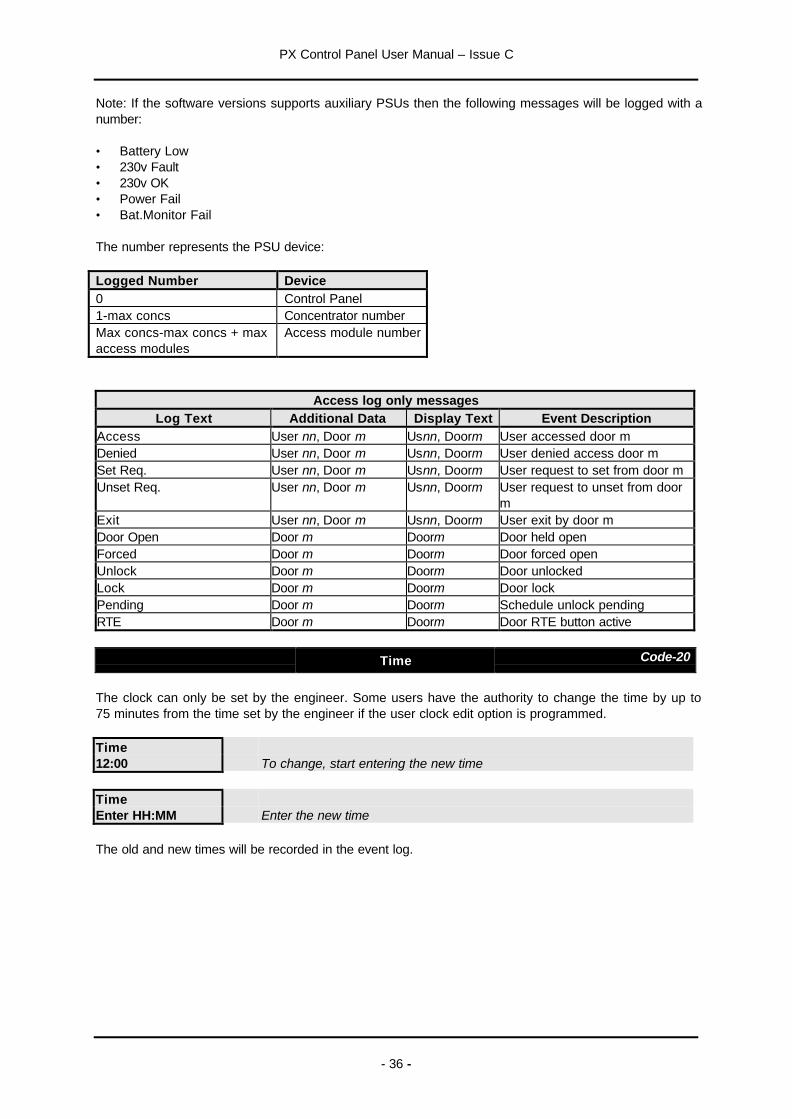
Note: If the software versions supports auxiliary PSUs then the following messages will be logged with anumber:
• Battery Low• 230v Fault• 230v OK• Power Fail• Bat.Monitor Fail
The number represents the PSU device:
Logged Number Device0 Control Panel1-max concs Concentrator numberMax concs-max concs + maxaccess modules
Access module number
Access log only messagesLog Text Additional Data Display Text Event Description
Access User nn, Door m Usnn, Doorm User accessed door mDenied User nn, Door m Usnn, Doorm User denied access door mSet Req. User nn, Door m Usnn, Doorm User request to set from door mUnset Req. User nn, Door m Usnn, Doorm User request to unset from door
mExit User nn, Door m Usnn, Doorm User exit by door mDoor Open Door m Doorm Door held openForced Door m Doorm Door forced openUnlock Door m Doorm Door unlockedLock Door m Doorm Door lockPending Door m Doorm Schedule unlock pendingRTE Door m Doorm Door RTE button active
Time Code-20
The clock can only be set by the engineer. Some users have the authority to change the time by up to75 minutes from the time set by the engineer if the user clock edit option is programmed.
Time12:00 To change, start entering the new time
TimeEnter HH:MM Enter the new time
The old and new times will be recorded in the event log.
PX Control Panel User Manual – Issue C
- 37 -
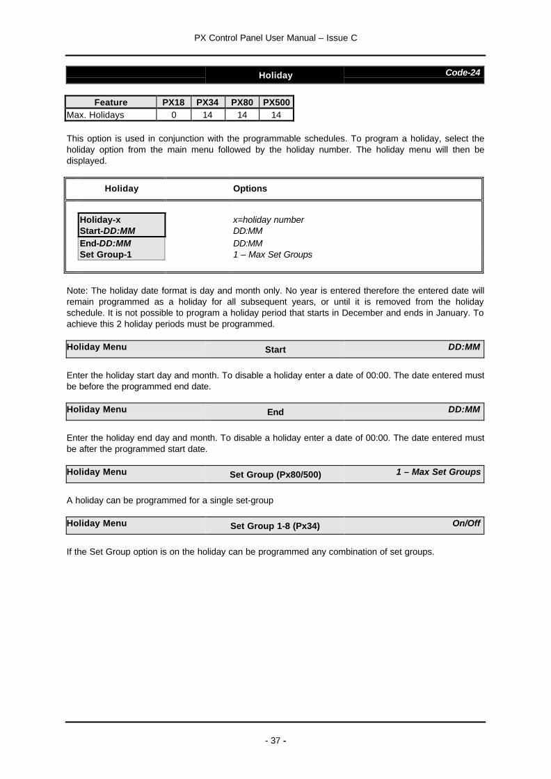
Holiday Code-24
Feature PX18 PX34 PX80 PX500Max. Holidays 0 14 14 14
This option is used in conjunction with the programmable schedules. To program a holiday, select theholiday option from the main menu followed by the holiday number. The holiday menu will then bedisplayed.
Holiday Options
Holiday-x x=holiday numberStart-DD:MM DD:MMEnd-DD:MM DD:MMSet Group-1 1 – Max Set Groups
Note: The holiday date format is day and month only. No year is entered therefore the entered date willremain programmed as a holiday for all subsequent years, or until it is removed from the holidayschedule. It is not possible to program a holiday period that starts in December and ends in January. Toachieve this 2 holiday periods must be programmed.
Holiday Menu Start DD:MM
Enter the holiday start day and month. To disable a holiday enter a date of 00:00. The date entered mustbe before the programmed end date.
Holiday Menu End DD:MM
Enter the holiday end day and month. To disable a holiday enter a date of 00:00. The date entered mustbe after the programmed start date.
Holiday Menu Set Group (Px80/500) 1 – Max Set Groups
A holiday can be programmed for a single set-group
Holiday Menu Set Group 1-8 (Px34) On/Off
If the Set Group option is on the holiday can be programmed any combination of set groups.

PX Control Panel User Manual – Issue C
- 38 -
Schedule (PX18 & 34) Code-25
Feature PX18 PX34Max. Schedules 4 8
A schedule can be used to:
1. Auto set and unset parts of the system2. Control outputs3. Enable/disable keypads4. Enable/disable user access
To program a schedule, select the schedule option from the main menu followed by the schedulenumber. The schedule menu will then be displayed.
Schedule Options
Schedule-x x=Schedule numberStart Time-00:00 HH:MMStop Time-00:00 HH:MMMon-Off On/OffTue-Off On/Off. . .Sun-Off On/OffHoliday-Off On/Off
Schedule Menu Start Time HH:MM
To disable a schedule the start and stop times should be set to 00:00.
Schedule Menu Stop Time HH:MM
To disable a schedule the start and stop times should be set to 00:00.
Schedule Menu Mon-Sun On/Off
Each schedule can be configured for any combination of days, if the start or stop times are non zero.The programmed schedule function will not operate on days that are programmed as off.
Schedule Menu Holiday On/Off
If the holiday option is on, then the schedule operation will be suspended on dates that are programmedas holidays.

PX Control Panel User Manual – Issue C
- 39 -
Schedule (PX80 & 500) Code-25
Feature PX80 PX500Max. Schedules 16 32
A schedule can be used to:
1. Auto set and unset parts of the system2. Control outputs3. Enable/disable keypads4. Enable/disable user access
To program a schedule, select the schedule option from the main menu followed by the schedulenumber. The day menu will then be displayed.
Schedule Options
1=Mon2=Tue3=Wed4=Thu5=Fri6=Sat7=Sun8=Hol
Select the day or holiday (Hol) to program the schedule times:
Schedule Options
Schedule-nn Day nn=Schedule number, Day= selected day or holidayStart 1-00:00 HH:MMStop 1-00:00 HH:MMStart 2-00:00 HH:MMStop 2-00:00 HH:MM
Two sets of times may be programmed for each schedule day. This allows, for example, 2 accessperiods to be configured for a user or 2 auto set/unset times.
Set Group Code-26
A descriptor of up to 10 characters may be entered for each set group. Refer to the user name sectionfor details of how to change a descriptor.

PX Control Panel User Manual – Issue C
- 40 -
Bypass Code-30
The bypass option will only be available if a circuit(s) has been programmed as bypassable by theinstallation engineer.
The bypass circuit option allows the user to bypass a circuit that is in a fault condition. When bypassedthe alarm condition of a circuit is ignored.
CircuitNumber-x
To bypass a circuit select the bypass option from the main menu, followedby the circuit number.
Circuit -xNormal The current state will be displayed
When a circuit is bypassed it is ignored until the bypass is automatically removed when the circuit isnext unset or until a user removes the bypass. All bypass actions are stored in the event log.
A bypass limit will have been programmed by the installation engineer to limit the number of circuits thatcan be bypassed at any one time. The system will display an error message if you try to exceed thislimit.
Keypad Off Code-31
A keypad can be disabled by an authorised user if required. Disabling a keypad will render all buttonson the keypad inoperative, however the keypad display will continue to operate normally.
To disable a keypad, enter the keypad number.
Keypad-xOn Press 0 to turn off or 1 to turn on.
12:00 Mon 27 SepOut of Service
A keypad that is turned off will show the time/date and out of servicemessage.
Not Available:Keypad Busy
You cannot turn off a keypad which is being used. If this is attempted awarning message will be displayed.
The installation engineer may also have programmed the system to turn off a keypad(s) at various timesof day. This allows, for example, a keypad in a public area to be turned off while the area is unset.
Chime Code-32
Certain circuit types can be selected as chime circuits when unset.
To select the chime function for a circuit, enter the circuit number.
Circuit -x The circuit descriptor will be displayed.Front Door Press any button to display the current chime status of the circuit.
Circuit -xChime-Off Press 0 to turn off or 1 to turn on.

PX Control Panel User Manual – Issue C
- 41 -
Printing Print Text Code-40
The print text option will print all text descriptors for users, circuits, set groups, and the company name.
Printing Print Hols. Code-42
The print holiday option will print all holiday periods.

PX Control Panel User Manual – Issue C
- 42 -
Access Features
The number of Access Modules that can be connected depends on the panel variant:
Feature PX18 PX34 PX80 PX500Access Modules 2 2 16 32
The table shows the access features across the panel range.
Feature PX18 PX34 PX80 PX500Doors 2 2 16 32Panel Users 20 40 100 200Access Users 20 40 1000 1000User expiry dates 7 7 3 3
Challenged user option 7 7 3 3
User lock out from keypad 7 7 3 3
Door lock/unlock from keypad 3 3 3 3
Programmable unlock time 3 3 3 3
Programmable Aux. relay time 3 3 3 3
Anti pass back 3 3 3 3
Access log events 1000 1000 1000 1000Access log real time print 3 3 3 3
Set & unset 3 3 3 3
Note: The panel users must be the first users in the system. For example on the PX 500 users 2-200may be access or panel users, users 201-1000 can only be access users and user 1 is always theengineer.
The PX access control system can be configured through a security system keypad or a PC runningGuardStation™ Access. Guardall PX proximity tokens may only be introduced to the system through aPX keypad with an integrated proximity reader.
The Access Module door input may be programmed as a circuit. Refer to the Input Map option fordetails.
Access System Security System Integration
1. The door contact may be programmed as a security panel entry/exit circuit or be given any othercircuit response.
2. An access system user can be programmed as a security system user.3. The door may not be unlocked while the access module area is set. The access module area is the
area that the door circuit is programmed for.4. All doors may be programmed to open if a fire alarm is reported from the security system.5. The door area may be set and unset from a Proximity reader.Outputs on the security system may be programmed to follow the state of a door circuit.
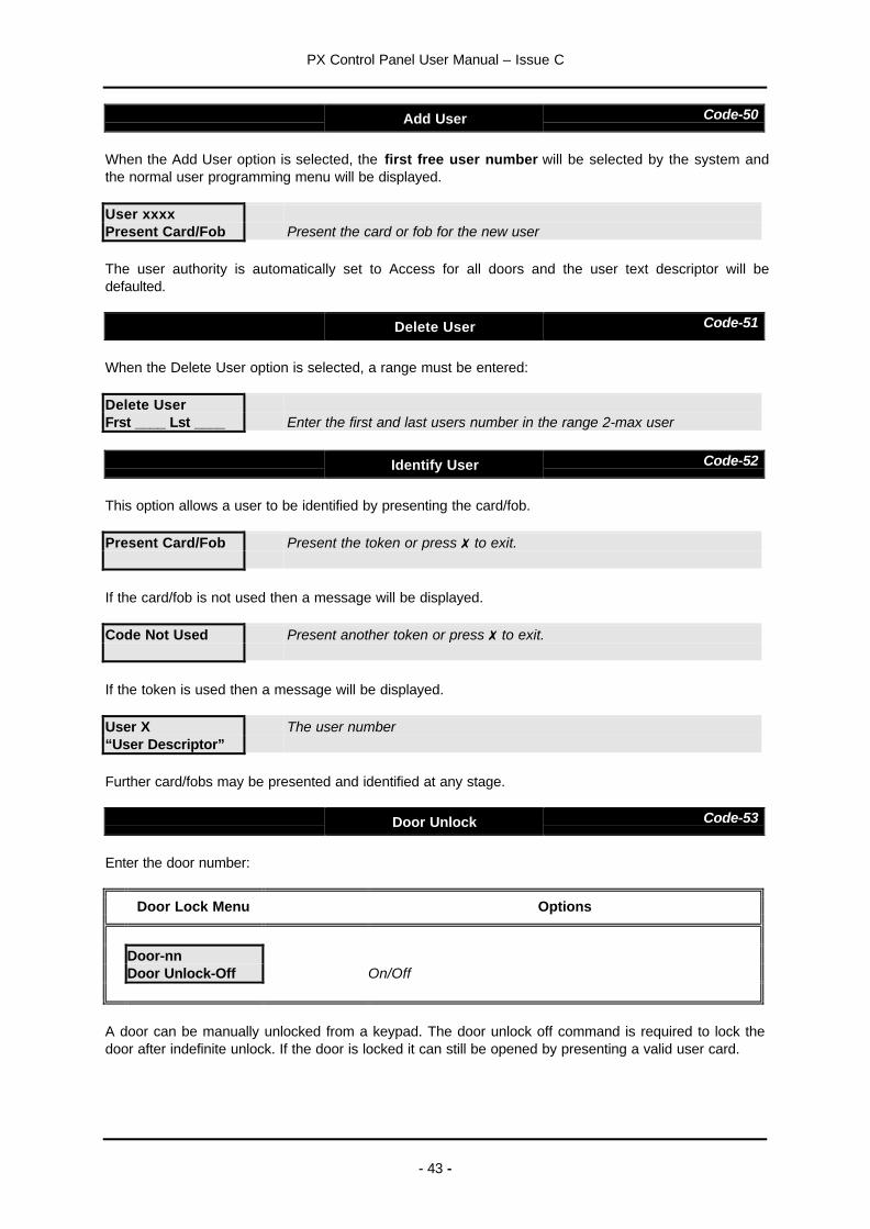
PX Control Panel User Manual – Issue C
- 43 -
Add User Code-50
When the Add User option is selected, the first free user number will be selected by the system andthe normal user programming menu will be displayed.
User xxxxPresent Card/Fob Present the card or fob for the new user
The user authority is automatically set to Access for all doors and the user text descriptor will bedefaulted.
Delete User Code-51
When the Delete User option is selected, a range must be entered:
Delete UserFrst ____ Lst ____ Enter the first and last users number in the range 2-max user
Identify User Code-52
This option allows a user to be identified by presenting the card/fob.
Present Card/Fob Present the token or press 7to exit.
If the card/fob is not used then a message will be displayed.
Code Not Used Present another token or press 7to exit.
If the token is used then a message will be displayed.
User X The user number“User Descriptor”
Further card/fobs may be presented and identified at any stage.
Door Unlock Code-53
Enter the door number:
Door Lock Menu Options
Door-nnDoor Unlock-Off On/Off
A door can be manually unlocked from a keypad. The door unlock off command is required to lock thedoor after indefinite unlock. If the door is locked it can still be opened by presenting a valid user card.

PX Control Panel User Manual – Issue C
- 44 -
Door Lockout Code-54
Enter the door number:
Door Lock Menu Options
Door-nnDoor Lockout-Off On/Off
The locked out door will remain locked and will refuse all access attempts until the lockout is removed.The door lockout can only be removed through this programming option. The door lockout will over-rideany user/door schedule permissions or otherwise immediately, and for the applied duration. Uponremoval the door will be returned to its previous state (if that state still applies). Proximity reader LED’swill show the door as locked out for the applied duration.
Door Text Code-55
A descriptor of up to 10 characters may be entered for each door. Refer to the user name section fordetails of how to change a descriptor.
Isolate Cct Code-86
The isolate circuit option will only be available if programmed by the installation engineer.
The isolate circuit operation enables a circuit to be isolated in case of a fault. When isolated the alarmand tamper condition of a circuit are ignored.
CircuitNumber-x Enter the circuit number
Circuit -xNormal The current state will be displayed
When a circuit is isolated it is ignored until the isolate is removed. Isolate can only be removed if thecircuit is in a clear condition.
Isolate Conc Code-87
The isolate concentrator option will only be available if programmed by the installation engineer.
This option enables a concentrator tamper to be isolated if a fault occurs.
ConcentratorNumber-x Enter the concentrator number
Isol Conc-xOff The current state will be displayed
When a concentrator is isolated it is ignored until the isolate is removed. Isolating a concentrator doesnot isolate circuits connected to the concentrator.

PX Control Panel User Manual – Issue C
- 45 -
Cct Status Code-89
The circuits that are on soak, bypassed or isolated can be displayed.
Cct StatusNormal
The display will scroll all circuits that are bypassed, isolated or shunted.

PX Control Panel User Manual – Issue C
- 46 -
System Details
Number of Areas
Number of keypads
Number of Circuits
Number of Users
Service Number
Contract Number
Keypads
Number Location
1
2
3
4
5
6
7
8
Set Groups
AreasNumber Description1 2 3 4 5 6 7 8
1
2
3
4
5
6
7

PX Control Panel User Manual – Issue C
- 47 -
AreasNumber Description1 2 3 4 5 6 7 8
8
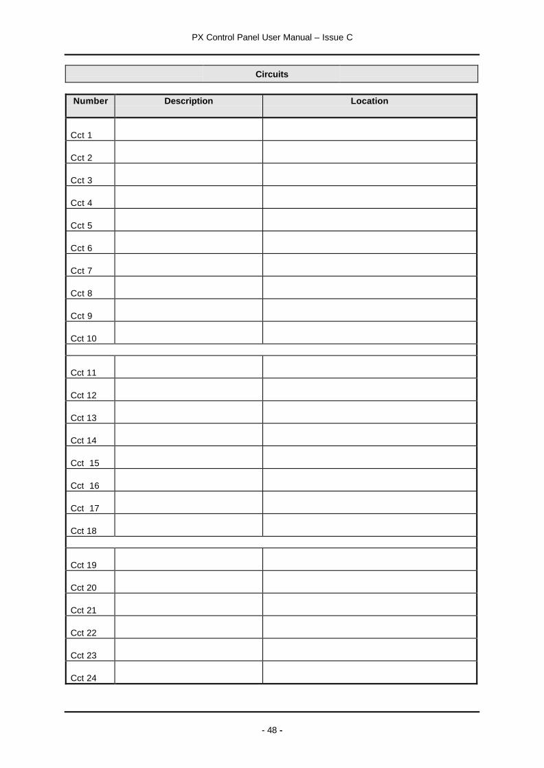
PX Control Panel User Manual – Issue C
- 48 -
Circuits
Number Description Location
Cct 1
Cct 2
Cct 3
Cct 4
Cct 5
Cct 6
Cct 7
Cct 8
Cct 9
Cct 10
Cct 11
Cct 12
Cct 13
Cct 14
Cct 15
Cct 16
Cct 17
Cct 18
Cct 19
Cct 20
Cct 21
Cct 22
Cct 23
Cct 24

PX Control Panel User Manual – Issue C
- 49 -
Number Description Location
Cct 25
Cct 26
Cct 27
Cct 28
Cct 29
Cct 30
Cct 31
Cct 32
Cct 33
Cct 34

PX Control Panel User Manual – Issue C
- 50 -
Users
Areas or Set GroupsNumber Name Authority Level1 2 3 4 5 6 7 8
2
3
4
5
6
7
8
9
10
11
12
13
14
15
16
17
18
19
20
21
22
23
24
25
26
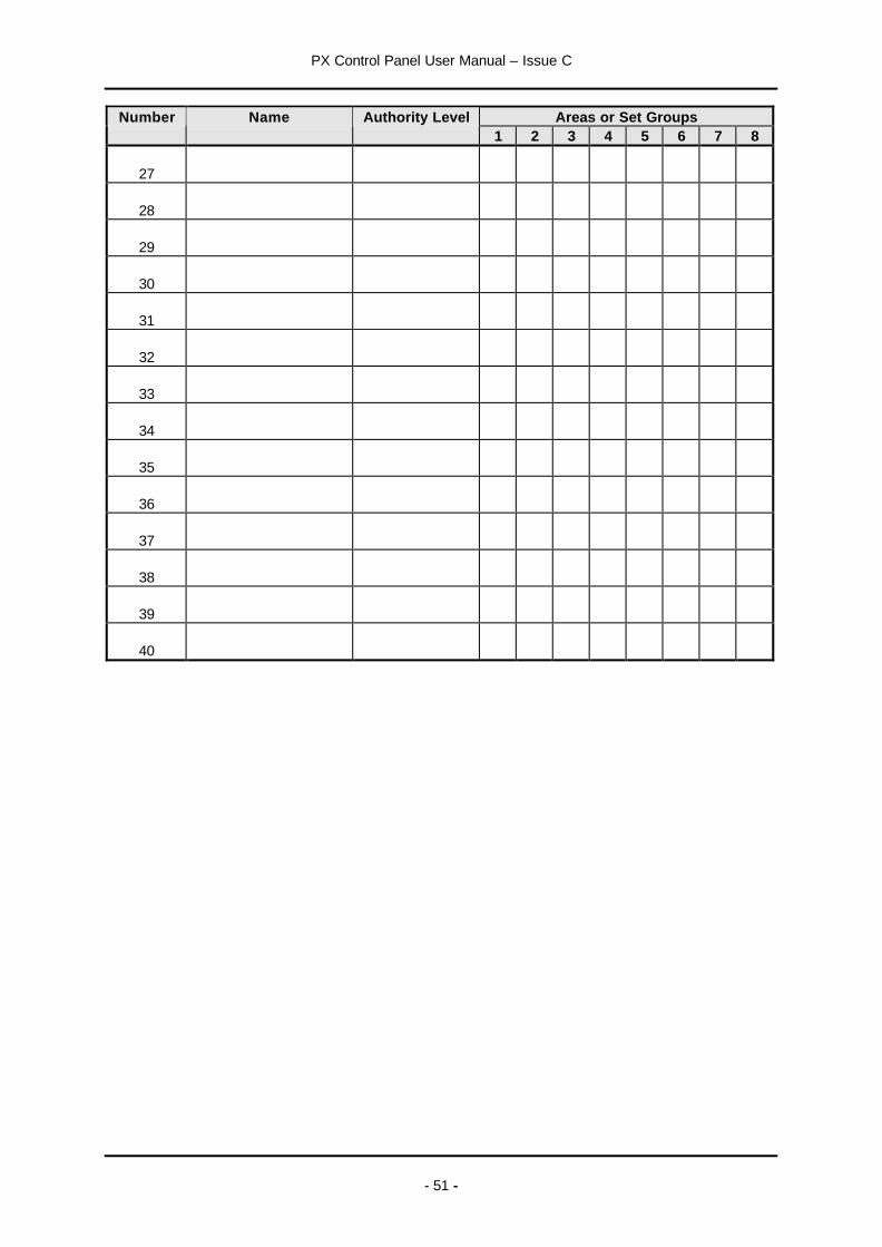
PX Control Panel User Manual – Issue C
- 51 -
Areas or Set GroupsNumber Name Authority Level1 2 3 4 5 6 7 8
27
28
29
30
31
32
33
34
35
36
37
38
39
40

Guardall LimitedLochend Industrial Estate
NewbridgeEdinburgh EH28 8PL
Tel: 0131-333-2900FAX: 0131-333-4919
Technical Hotline: 0131-333-3802
Part Number: 320680-0C