3/2, 5/2 and 5/3 Directional Control Valves - ARA Pneumatik · 45 Series S9 – G1/8 to G1/2...
13
44 Series S9 – G1/8 to G1/2 Characteristics Symbol Unit Series S9 G1/8 Actuation Manual control pneumatic electrical General Features Type Spool valve Mounting 2 Screws M5 Tube connection Thread Thread G1/8 – 7.4 deep Weight kg See page 48, 56, 64 Installation In any position Ambient temperature range ( 1 T min. / max. °C -10 to +60 * Medium temperature range ( 1 T min. / max. °C -10 to +60 * Medium Filtered compressed air Lubrication With or without oil mist lubrication (We recommend the use of mineral oil type VG 32 to ISO 3448) Pneumatische Characteristics Nominal pressure p min. / max. bar 6 Operating pressure range p min. / max. bar 0–10 ( 10 – – – permanent signal version p min. / max. bar – 0–10 2–10 – impulse version p min. / max. bar – 0–10 2–10 – with external pilot air p min. / max. bar – – 0–10 Nominal flow QN l/min 500 (450 bei 3/2 Way Valve) Actuation Manual control Direct Stroke mm 4.5 Actuation force Fb N 7 ( 2 10 ( 3 Actuation force for panel mounting actuators See page 48 Pneumatic Direct Actuation pressure range – permanent signal version p min. / max. bar – 2–10 2–10 – impulse version p min. / max. bar – 1.5–10 1.5–10 Electrical Electrical pilot operated Voltage type Alternating current (50/60Hz) Nominal voltage – Standard version Un V 230 ± 10% – Low wattage version Un V 230 ± 10% Initial power consumption G1/8 G1/4 G1/2 – Standard version VA (W) 8.5 8.5 11.0 – Low wattage version VA (W) 6.6 6.6 7.8 Continuous consumption G1/8 G1/4 G1/2 – Standard version VA (W) 6.0 6.0 8.5 – Low wattage version VA (W) 3.9 4.9 4.9 Duty cycle ED % 100 Electrical protection IP IP65 to DIN 40050 (applise only to solenoid with plug) Connection Plug to DIN EN 175301-803 form B – industrial standard ( 6 * Valve Manifold Assemblies with electrically actuated valves -10 to +50°C ( 1 Note: For use below freezing point please contact us ( 2 Actuation force for valves without spring return, actuation with rotary lever: 5N ( 3 Actuation force for valves with spring return, Actuation with rotary lever: 15N ( 4 Only for version with biased position 2 – 10 bar, pneumatically actuated 2 – 10 bar, electrically actuated 2.5 – 10 bar ( 5 Version with biased position 2.5 – 10 bar ( 6 Low wattage version: Plug to DIN EN 175301-803 form A ( 7 Version “middle position vented“ 1000 l/min ( 8 Version “middle position vented“ 3300 l/min Version “middle position pressured“ 3600 l/min ( 9 5/3 Way Valve 2.5 – 10 bar ( 10 Valves with panel mounting actuators 2 – 10 bar 3/2, 5/2 and 5/3 Directional Control Valves Series S9-G1/8 to G1/2
Transcript of 3/2, 5/2 and 5/3 Directional Control Valves - ARA Pneumatik · 45 Series S9 – G1/8 to G1/2...

44
Series S9 – G1/8 to G1/2Characteristics Symbol Unit Series S9 Series S9 Series S9
G1/8 G1/4 G1/2
Actuation Manual control pneumatic electrical Manual control pneumatic electrical Manual control pneumatic electrical
General FeaturesType Spool valve Spool valve Spool valveMounting 2 Screws M5 2 Screws M6 2 Screws M6Tube connection Thread Thread ThreadThread G1/8 – 7.4 deep G1/4 – 11 deep G1/2 – 16 deepWeight kg See page 48, 56, 64 See page 52, 60, 66 See page 54, 62, 68Installation In any position In any position In any positionAmbient temperature range (1 Tmin. / max. °C -10 to +60 * -10 to +60 * -10 to +60 *
Medium temperature range (1 Tmin. / max. °C -10 to +60 * -10 to +60 * -10 to +60 *Medium Filtered compressed airLubrication With or without oil mist lubrication
(We recommend the use of mineral oil type VG 32 to ISO 3448)Pneumatische CharacteristicsNominal pressure pmin. / max. bar 6 6 6Operating pressure range pmin. / max. bar 0–10 (10 – – 0–10 – – 0–10 – –– permanent signal version pmin. / max. bar – 0–10 2–10 – 0–10 2–10 – 0–10 2.2–10– impulse version pmin. / max. bar – 0–10 2–10 – 0–10 2–10 – 0–10 2.2–10– with external pilot air pmin. / max. bar – – 0–10 – – 0–10 – – 0–10Nominal flow QN l/min 500 (450 bei 3/2 Way Valve) 1300(7 3500(8
ActuationManual control Direct Direct DirectStroke mm 4.5 6.5 9.4Actuation force Fb N 7 (2
10 (310 (2
15 (315 (2
40 (3
Actuation force for panel mounting actuators
See page 48 – –
Pneumatic Direct Direct DirectActuation pressure range– permanent signal version pmin. / max. bar – 2–10 2–10 2–10 2–10 2–10 – 2.2–10(9 2.2–10– impulse version pmin. / max. bar – 1.5–10 1.5–10 1.5–10 1.5–10(4 1.5–10(4 – 1.5–10(5 1.5–10(4
Electrical Electrical pilot operatedVoltage type Alternating current (50/60Hz) Direct currentNominal voltage– Standard version Un V 230 ±10% 24 ±10% Other voltages on request– Low wattage version Un V 230 ±10% 24 ±10%Initial power consumption G1/8 G1/4 G1/2 G1/8 G1/4 G1/2– Standard version VA (W) 8.5 8.5 11.0 2.5 2.5 4.8– Low wattage version VA (W) 6.6 6.6 7.8 2.1 2.1 2.7Continuous consumption G1/8 G1/4 G1/2 G1/8 G1/4 G1/2– Standard version VA (W) 6.0 6.0 8.5 2.5 2.5 4.8– Low wattage version VA (W) 3.9 4.9 4.9 2.1 2.1 2.7Duty cycle ED % 100Electrical protection IP IP65 to DIN 40050 (applise only to solenoid with plug)
Connection Plug to DIN EN 175301-803 form B – industrial standard (6
* Valve Manifold Assemblies with electrically actuated valves -10 to +50°C
(1 Note: For use below freezing point please contact us(2 Actuation force for valves without spring return, actuation with rotary lever: 5N(3 Actuation force for valves with spring return, Actuation with rotary lever: 15N(4 Only for version with biased position 2 – 10 bar, pneumatically actuated 2 – 10 bar, electrically actuated 2.5 – 10 bar(5 Version with biased position 2.5 – 10 bar(6 Low wattage version: Plug to DIN EN 175301-803 form A(7 Version “middle position vented“ 1000 l/min(8 Version “middle position vented“ 3300 l/min Version “middle position pressured“ 3600 l/min(9 5/3 Way Valve 2.5 – 10 bar(10 Valves with panel mounting actuators 2 – 10 bar
3/2, 5/2 and 5/3 Directional Control ValvesSeries S9-G1/8 to G1/2

45
Series S9 – G1/8 to G1/2Characteristics Symbol Unit Series S9 Series S9 Series S9
G1/8 G1/4 G1/2
Actuation Manual control pneumatic electrical Manual control pneumatic electrical Manual control pneumatic electrical
General FeaturesType Spool valve Spool valve Spool valveMounting 2 Screws M5 2 Screws M6 2 Screws M6Tube connection Thread Thread ThreadThread G1/8 – 7.4 deep G1/4 – 11 deep G1/2 – 16 deepWeight kg See page 48, 56, 64 See page 52, 60, 66 See page 54, 62, 68Installation In any position In any position In any positionAmbient temperature range (1 Tmin. / max. °C -10 to +60 * -10 to +60 * -10 to +60 *
Medium temperature range (1 Tmin. / max. °C -10 to +60 * -10 to +60 * -10 to +60 *Medium Filtered compressed airLubrication With or without oil mist lubrication
(We recommend the use of mineral oil type VG 32 to ISO 3448)Pneumatische CharacteristicsNominal pressure pmin. / max. bar 6 6 6Operating pressure range pmin. / max. bar 0–10 (10 – – 0–10 – – 0–10 – –– permanent signal version pmin. / max. bar – 0–10 2–10 – 0–10 2–10 – 0–10 2.2–10– impulse version pmin. / max. bar – 0–10 2–10 – 0–10 2–10 – 0–10 2.2–10– with external pilot air pmin. / max. bar – – 0–10 – – 0–10 – – 0–10Nominal flow QN l/min 500 (450 bei 3/2 Way Valve) 1300(7 3500(8
ActuationManual control Direct Direct DirectStroke mm 4.5 6.5 9.4Actuation force Fb N 7 (2
10 (310 (2
15 (315 (2
40 (3
Actuation force for panel mounting actuators
See page 48 – –
Pneumatic Direct Direct DirectActuation pressure range– permanent signal version pmin. / max. bar – 2–10 2–10 2–10 2–10 2–10 – 2.2–10(9 2.2–10– impulse version pmin. / max. bar – 1.5–10 1.5–10 1.5–10 1.5–10(4 1.5–10(4 – 1.5–10(5 1.5–10(4
Electrical Electrical pilot operatedVoltage type Alternating current (50/60Hz) Direct currentNominal voltage– Standard version Un V 230 ±10% 24 ±10% Other voltages on request– Low wattage version Un V 230 ±10% 24 ±10%Initial power consumption G1/8 G1/4 G1/2 G1/8 G1/4 G1/2– Standard version VA (W) 8.5 8.5 11.0 2.5 2.5 4.8– Low wattage version VA (W) 6.6 6.6 7.8 2.1 2.1 2.7Continuous consumption G1/8 G1/4 G1/2 G1/8 G1/4 G1/2– Standard version VA (W) 6.0 6.0 8.5 2.5 2.5 4.8– Low wattage version VA (W) 3.9 4.9 4.9 2.1 2.1 2.7Duty cycle ED % 100Electrical protection IP IP65 to DIN 40050 (applise only to solenoid with plug)
Connection Plug to DIN EN 175301-803 form B – industrial standard (6
48
94
29
22
720
1837
3
2
1
11,5
40
50
G1/8
4131,5
5
5,5
19°
77
10
12
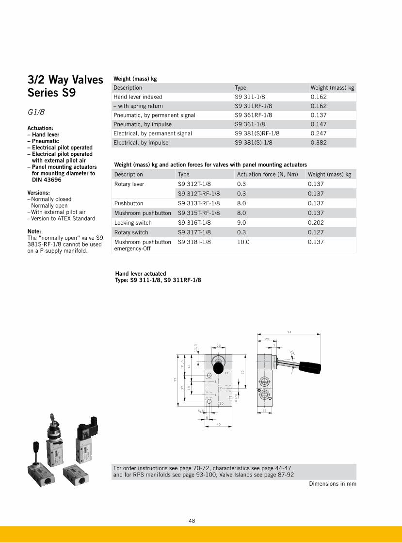
Hand lever actuated Type: S9 311-1/8, S9 311RF-1/8
Weight (mass) kg
Description Type Weight (mass) kg
Hand lever indexed S9 311-1/8 0.162
– with spring return S9 311RF-1/8 0.162
Pneumatic, by permanent signal S9 361RF-1/8 0.137
Pneumatic, by impulse S9 361-1/8 0.147
Electrical, by permanent signal S9 381(S)RF-1/8 0.247
Electrical, by impulse S9 381(S)-1/8 0.382
Weight (mass) kg and action forces for valves with panel mounting actuators
Description Type Actuation force (N, Nm) Weight (mass) kg
Rotary lever S9 312T-1/8 0.3 0.137
S9 312T-RF-1/8 0.3 0.137
Pushbutton S9 313T-RF-1/8 8.0 0.137
Mushroom pushbutton S9 315T-RF-1/8 8.0 0.137
Locking switch S9 316T-1/8 9.0 0.202
Rotary switch S9 317T-1/8 0.3 0.127
Mushroom pushbuttonemergency-0ff
S9 318T-1/8 10.0 0.137
For order instructions see page 70-72, characteristics see page 44-47and for RPS manifolds see page 93-100, Valve Islands see page 87-92
3/2 Way ValvesSeries S9
G1/8
Actuation:– Hand lever– Pneumatic– Electrical pilot operated– Electrical pilot operated with external pilot air– Panel mounting actuators for mounting diameter to DIN 43696
Versions:– Normally closed– Normally open– With external pilot air – Version to ATEX Standard
Note:The “normally open“ valve S9 381S-RF-1/8 cannot be used on a P-supply manifold.
Dimensions in mm

49
Pneumatically actuated – Type: S9 361-1/8, S9 361RF-1/8
Electrically actuated – Type: S9 381(S)-1/8, S9 381(S)RF-1/8
2
42,5
G1/8
15,5
40
63S9 381 -1/8S9 381S-1/8
1
3
10
12
(1)
(3)
(10)
(12)
3,2
5,6
8
5
pst
pst
1837
69,5
5,5
M510,5
33,524
15,5
110
56 5
G1/8 24,5
36
*
*
**
**16,6
22***
ca.
122
ca.
190
* Manual override** Operating pressure supply pst only for type S9 381S*** Solenoid width = 30 mm on low wattage coil version
only for type
��
��
����
���
���
��
���
�
�
�
�
��
���
����
�
�
�
��
�
����
�
����
��
��
�
only for type
S9361-1/8
��
����
�
�����
� �����
��
�
Solenoid for use in EX areas – Dimensions
For more information on valves to ATEX standards see page 46, 47, 72
X = 15,5 mm
Cable lenth see Order Instructions
Solenoid width 30 mm
For order instructions see page 70-72, characteristics see page 44-47P-Manifolds and for RPS manifolds see page 93-100, Valve Islands see page 87-92
Dimensions in mm
50
1837
3
2
1
40
47
G1/8
3828
5
5,5
74
10
12
22
28
40
76,5
�������
��������
����
����
����
����
�������
��������
����
����
∅��
����
�������
����
��°
���
��
���
���
��
��
�������
���
����
����
�
���
∅��
�������
����
��
���
��
����
�
����
�������
∅��
���
��
���
���
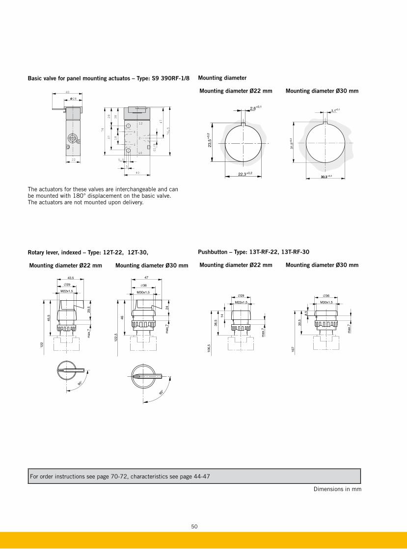
Basic valve for panel mounting actuatos – Type: S9 390RF-1/8
The actuators for these valves are interchangeable and can be mounted with 180° displacement on the basic valve.The actuators are not mounted upon delivery.
Mounting diameter
Mounting diameter Ø22 mm Mounting diameter Ø30 mm
Rotary lever, indexed – Type: 12T-22, 12T-30,
Mounting diameter Ø22 mm Mounting diameter Ø30 mm
Pushbutton – Type: 13T-RF-22, 13T-RF-30
Mounting diameter Ø22 mm Mounting diameter Ø30 mm
For order instructions see page 70-72, characteristics see page 44-47
Dimensions in mm

51
�������
��
��
∅�����
����
���
����
����
�������
∅��
���
��
���
����
�
����
Mushroom pushbutton – Type: 15T-RF-22, 15T-RF-30
Mounting diameter Ø22 mm Mounting diameter Ø30 mm
∅��
����
�������
����
��°
���
��
���
��
�������
���
����
��°
����
�
∅��
�������
��
��∅����
���
��
���
����
����
�������
∅����
���
�����
����
�
����
��°
��
��
�������
∅��
���
����
����
�
����
∅��
����
�������
����
��°
���
��
���
∅��
�������
��
��
��
���
��
����
�
����
�������
∅��
���
����
��
��
���
Rotary lever with spring return – Type: 12T-RF-22, 12T-RF-30
Mounting diameter Ø22 mm Mounting diameter Ø30 mm Mushroom pushbutton emergency-0ff – Type: 18T-22, 18T-30
Mounting diameter Ø22 mm Mounting diameter Ø30 mm
Rotary switch – Type: 17T-22, 17T-30
Mounting diameter Ø22 mm Mounting diameter Ø30 mm
Locking switch – Type: 16T-22, 16T-30
Mounting diameter Ø22 mm Mounting diameter Ø30 mm

52
12
17
44
120
18°
32
98
22
3
1
2
25
52
12
6
6,5
10
4742,5
55
66
G1/4
12
17
44
120
18°
32
98
22
3
1
2
25
52
12
6
6,5
10
4742
,5
55
66
G1/4
3/2 Way ValvesSeries S9
G1/4
Actuation systems:– Hand lever– Pneumatic– Electrical pilot operated– Electrical pilot operated with external pilot air
Versions:– Normally closed– Normally open– With external pilot air – With biased position– Version to ATEX Standard
Hand lever actuated – Type: S9 311-1/4, S9 311RF-1/4
Weight (mass) kg
Description Type Weight (mass)
Hand lever, indexed S9 311-1/4 0.370
– with spring return S9 311RF-1/4 0.370
Safety hand lever S9 311S-1/4 0.370
Rotary lever, indexed S9 312-1/4 0.370
– with spring return S9 312RF-1/4 0.370
Pneumatic, by permanent signal S9 361RF-1/4 0.370
Pneumatic, by impulse S9 361-1/4 0.430
– with biased position S9 362-1/4 0.430
Electrical, by permanent signal S9 381(S) RF-1/4 0.500
Electrical, by impulse S9 381(S)-1/4 0.600
– with biased position S9 382(S)-1/4 0.600
Safety hand lever actuated – Type: S9 311S-1/4

53
12
17
44
32
98
22
3
1
2
52
12
6
10
47
55
66
G1/4
33° 33°
65
79,5
25
6,5
42,5
Pneumatically actuated – Type: S9 361-1/4, S9 362-1/4, S9 361RF-1/4
Rotary lever actuated – Type: S9 312-1/4, S9 312RF-1/412
,5
21
224776,5
32
33,5
G1/4
11
5,5
25
52
6
6,5
4422
,5G1/8
44,5
3
2
1
10
12
o 4,
2
o 7,
5
4,5
12,5
only for typeS9 361-1/4S9 362-1/4
Electrically actuated – Type: S9 381(S)-1/4, S9 382(S)-1/4, S9 381(S)RF-1/4
* Manual override** Operating pressure supply pst only for type S9 381S*** Solenoid width = 30 mm on low wattage coil version
Note:The “normally open“ valve S9 381S-RF-1/4 cannot be used on a P-supply manifold.
���
��
����
��
��
�
�
�
��
��
��
����
��
���
��
��
��
��
��
���
��
������������������������������������������
���
���
����
����
����
�
�����
���
���
�
���
�
���
��
����
��
���
��
���
�
���
�����
��
�����
��only for type
��
����
�
�����
� �����
��
�X = 15.5 mm
Cable lenth see Order Instructions
Solenoid width 30 mm
For order instructions see page 70-72, characteristics see page 44-47
Dimensions in mm
Solenoid for use in EX areasDimensions
For more information on valves to ATEX standards see page 46, 47, 72

54
���
��
��
�
���
���
��
��
��
��
��
������
���
���
�
��
��
��
�
�
�
���
��
��
�
���
���
��
��
��
��
��
������
���
���
�
��
��
��
�
�
�
Hand lever actuated – Type: S9 311-1/2, S9 311RF-1/2
Safety hand lever actuated – Type: S9 311S-1/2
3/2 Way ValvesSeries S9
G1/2
Actuation systems:– Hand lever– Pneumatic– Electrical pilot operated– Electrical pilot operated with external pilot air
Versions:– Normally closed– Normally open– With external pilot air – With biased position – Version to ATEX Standard
Weight (mass) kg
Description Type Weight (mass)
Hand lever, indexed S9 311-1/2 0.900
– with spring return S9 311RF-1/2 0.900
Safety hand lever S9 311S-1/2 0.900
Rotary lever, indexed S9 312-1/2 0.950
–with spring return S9 312RF-1/2 0.950
Pneumatic, by permanent signal S9 361RF-1/2 0.700
Pneumatic, by impulse S9 361-1/2 0.650
– with biased position S9 362-1/2 0.650
Electrical, by permanent signal S9 381(S) RF-1/2 0.770
Electrical, by impulse S9 381(S)-1/2 1.008
– with biased position S9 382(S)-1/2 1.008

55
��
��
�
���
��
��
��
��
��
����
��
���
���
�
��
��
��
�
�
�
��
�����
Pneumatically actuated – Type: S9 361-1/2, S9 361RF-1/2
Rotary lever actuated – Type: S9 312-1/2, S9 312RF-1/2
���
�
��
���
�
��
��
�
�
�
��
����
���
���
�� ��
��
���
�
��
���
�
��
���
����
����
���
only for typeS9 361-1/2S9 362-1/2
6 d
eep
Electrically actuatedType: S9 381(S)-1/2, S9 382(S)-1/2, S9 381(S)RF-1/2
* Manual override** Operating pressure supply pst only for type S9 381S*** Solenoid width = 30 mm on low wattage coil version
Note:The “normally open“ valve S9 381S-RF-1/2 cannot be used on a P-supply manifold.
���
��
��
��
�
�
�
����
����
���
���
�� ��
���
�
���
��
��
��
��
��
�����
���
���
�
�
���
��
��
��
��
�����
���
���
����
����
6 de
ep
only for typeS9 581(S)-1/2S9 582(S)-1/2
Solenoid for use in EX areasDimensions
For more information on valves to ATEX standards see page 46, 47, 72
��
����
�
�����
� �����
��
�X = 21 mm
Cable lenth see Order Instructions
Solenoid width 30 mm
For order instructions see page 70-72, characteristics see page 44-47
Dimensions in mm

70
2
1 3
12
2
1 3
12 10
2
1 3
12
2
1 3
12
2
1 3
12 10
2
1 3
12 10
2
1 3
12 10
2
1 3
12 10
2
1 3
1210
3/2 Way Valves – Standard versionsActuation System Symbol Mounting
Ø (mm)Order Instructions Page
Type Order No.
Hand lever,indexed
S9 311-1/8 PA 10293 48
S9 311-1/4 PA 12708 52
S9 311-1/2 PA 16404 54
Hand lever,spring return
S9 311RF-1/8 PA 10294 48
S9 311RF-1/4 PA 12709 52
S9 311RF-1/2 PA 16405 54
Hand lever secured in 2 switchingpositions
S9 311S-1/4 PA 12710 52
S9 311S-1/2 PA 16406 54
Rotary lever,indexed S9 312-1/4 PA 12711 53
S9 312-1/2 PA 16407 45
Rotary lever,spring return S9 312RF-1/4 PA 12712 53
S9 312RF-1/2 PA 16408 55
Pneumatic,by permanent signal
S9 361RF-1/8 PA 10295 49
S9 361RF-1/4 PA 12713 53
S9 361RF-1/2 PA 16409 55
Pneumatic,by impulse
S9 361-1/8 PA 10296 49
S9 361-1/4 PA 12714 53
S9 361-1/2 PA 16410 55
Pneumatic, by impulse,with biased position S9 362-1/4 PA 12715 53
S9 362-1/2 PA 16411 55
Basic valve forpanel mounting
S9 390RF-1/8 PA 10307 50
Rotary lever,indexed
22 12T-22 KX 9355 50
30 12T-30 KX 9314
Rotary lever,spring return
22 12T-RF-22 KX 9356 51
30 12T-RF-30 KX 9315
Pushbutton 22 13T-RF-22 KX 9357 50
30 13T-RF-30 KX 9316
Mushroom pushbutton 22 15T-RF-22 KX 9358 51
30 15T-RF-30 KX 9317
Locking switch 22 16T-22 KX 9359 51
30 16T-30 KX 9318

71
2
1 3
1012
2
1 3
1210
12
3
2
1
14
stp
2
1 3
12 10
2
1 3
14 12
pst
2
1 3
14 12
pst
2
1 3
14 12
pst pst
Actuation System Symbol Mounting Ø (mm)
Order Instructions Page
Type Order No.
Rotary switch 22 17T-22 KX 9360 51
30 17T-30 KX 9319
Mushroom pushbuttonemergency-0ff
22 18T-22 KX 9361 51
30 18T-30 KX 9320
Electricalby permanent signal
S9 381RF-1/8-NC-.. PA 10297-..33 49
S9 381RF-1/4-NC-.. PA 12716-..33 53
S9 381RF-1/2-NC-.. PA 16412-..33 55
S9 381RF-1/8-NO-.. PA 10298-..33 49
S9 381RF-1/4-NO-.. PA 12717-..33 53
S9 381RF-1/2-NO-.. PA 16413-..33 55
with external pilot air S9 381S-RF-1/8-.. PA 10300-..33 49
S9 381S-RF-1/4-.. PA 12719-..33 53
S9 381S-RF-1/2-.. PA 16415-..33 55
Electrical by impulse
S9 381-1/8-.. PA 10299-..33 49
S9 381-1/4-.. PA 12718-..33 53
S9 381-1/2-.. PA 16414-..33 55
Electrical, by impulse,with external pilot air
S9 381S-1/8-.. PA 10301-..33 49
S9 381S-1/4-.. PA 12720-..33 53
S9 381S-1/2-.. PA 16417-..33 55
Electrical by impulse,with biased position S9 382-1/4-.. PA 12721-..33 53
S9 382-1/2-.. PA 16418-..33 55
with external pilot air
S9 382S-1/4-.. PA 12722-..33 53
S9 382S-1/2-.. PA 16419-..33 55
Solenoid version Nominal voltage Applicable for Key code ATEX Type additon
Standard version 230V 50/60Hz 110 V = 61 –
24V = 60V 50/60Hz 02 –
Low wattage version 24V = 13 –
230V 50/60Hz 69 –
EX Area versions to ATEX standard see page 72

72
EX Area versions to ATEX StandardCategory, type of ignition protectionSingle valve: II 2G c T4 T135°C -10°C≤Ta≤+60°CSolenoid/individual use: II 2G EEx m II T5 -20°C≤Ta≤+50°CSolenoid/manifold mounting: II 2G EEx m II T5 -20°C≤Ta≤+40°C
Solenoid version Nominal voltage
Applicable for Key code ATEX Type ad-diton
Solenoid – with cable 1.2 m
24V = 48 ATEX
– with cable 3 m 24V = 45 ATEX
– with cable 5 m 24V = 46 ATEX
– with cable 10 m 24V = 47 ATEX
– with cable 1.2 m 24V 50/60Hz 99 ATEX
– with cable 1.2 m 110V 50/60Hz 97 ATEX
– with cable 1.2 m 230V 50/60Hz 98 ATEX
Example for valves in ATEX-Version:– for valves Series S9-G1/8, S9-G1/4, S9-G1/2Please add behind the Standard Order No. “ATEX“Type: S9 381RF-1/8-NC-4633Order No. PA10297-4633ATEX