aircar.com 31.pdf · cycling recorder. The recording ... Mounted at Stn.636.0 and connected by an...
40
Transcript of aircar.com 31.pdf · cycling recorder. The recording ... Mounted at Stn.636.0 and connected by an...


Jun 30/0131-31-00 Page 1EFFECTIVITY: All
zSD3-60 AIRCRAFT MAINTENANCE MANUAL
AMM31-31-00 1.0.0.0FLIGHT DATA RECORDING SYSTEM - DESCRIPTION & OPERATION
1. Description
A. General
This system acquires operational data from other aircraft systems, processes it into serial digital form in a programmed sequence and then records it on an accident protected re-cycling recorder. The recording retains data pertaining to the last 25.12 to 27.25 hours of flight. Facilities are provided for the entire recording to be played back to a copy recorder in approximately 20 minutes while the unit is still installed in the aircraft.
The equipment consists of a data acquisition and recorder unit (DARU), a flight data entry panel (FDEP), an accelerometer, transducers for airspeed and altitude, together with potentiometers for control surface movement. Other parameters which are also recorded are taken from the propeller tacho-generators, engine torque pressure transmitters and a vertical gyro. Discrete (on-off) signals are provided by propeller pitch warning lamp relays, the pilots' press-to-transmit switches and the event switch on the FDEP.
B. Detail
(1) Data acquisition and recorder unit - Plessey Type PV1584/G
This unit, which consists of a recorder and the data acquisition electronics, is housed in a 1/2 ATR long case mounted on a tray (Plessey Type PV1586) attached to the fuselage structure on the left side of the tail compartment.
The construction of the unit is such that the recorder is a module which is mechanically and thermally protected against accident.
The recording medium is mylar based magnetic tape. The two tape spools are mounted coaxially, the drive capstan being coupled by a v-belt to a motor external to the recorder module. Four head assemblies, two record and two playback, each with three heads provide for a six track recording and playback, with adjacent tracks being recorded in opposite directions along the tape.
Connections to the aircraft wiring are made via two 106-way sockets at the rear of the unit. A test socket connected to these connectors is mounted just below the unit to provide for the connection of a flight line test set and a copy recorder.
(2) Flight data entry panel, Plessey Type PV1591A
Refer to Figure 1.
This panel is mounted by means of DZUS fasteners on panel 1P at the 2nd pilot's position. It provides facilities for manually inserting flight data into the recording and for checking the status of the flight data recording system by means of the following switches and indicators:-

Jun 30/0131-31-00 Page 2EFFECTIVITY: All
zSD3-60 AIRCRAFT MAINTENANCE MANUAL
(a) EVENT button
When pressed, this button supplies a discrete signal to the DARU to insert a marker into the recording to call attention to any particular event.
(b) DDI button
The documentary data insert button supplies a discrete signal to the DARU, when pressed, to insert a marker in the recording to identify a change of documentary data.
(c) Documentary data selector switches
Eight 10-position thumbwheel switches provide manual selection of individual decimal digits for DAY (2 digits) MONTH (2 digits) FLT. LEG (1 digit) FLIGHT No. (3 digits). The switches are scanned in turn, each for one frame period, to record the documentary data.
(d) GROUND CHECK switch
This switch by-passes the aircraft flying controls interlock circuit to allow the flight data recording system to be operated with the aircraft on the ground.
(e) Status indicator
This indicator contains a lamp which only lights on a fault condition. It will remain unlit while fault conditions are absent, but will light when the indicator is pressed, thereby providing a check on the lamp filament, the presence of power and the validity of the no fault indication. It flashes briefly during tape reversal.
Electrical connections to the flight data entry panel are via a multi-pin connector at the rear.
(3) Accelerometer, three axis Sundstrand Type 971-4193-001
The accelerometer is mounted in the fuselage roof aft of frame 249 and slightly to the left of the aircraft centre line. Although the unit has 3 axis capability, only two of the parameters are supplied to the DARU:-
(a) On aircraft pre Serv. Bull. SD360-31-05, only vertical and lateral acceleration are recorded.
(b) On aircraft post mod A8472 or post Serv. Bull. SD360-31-05, only vertical and longitudinal acceleration are recorded.
The instrument has an operating range of -3g to +6g vertical and ±1g lateral and longitudinal. Signal outputs are 200 to 5000 mV dc. and the null points are at +1800mV vertical and 2600 mV lateral and longitudinal, ±25mV d.c. in all cases.

Jun 30/0131-31-00 Page 3EFFECTIVITY: All
zSD3-60 AIRCRAFT MAINTENANCE MANUAL
(4) Transducer, airspeed, SE Labs (EMI) Ltd., Type SE40/L/041/Vgg/0 to 2PSI/d
This unit is mounted on a plate on the right side of the fuselage just forward of the pilots instrument panel. It is a capsule type instrument and is connected into the aircraft pitot system to produce a signal proportional to aircraft airspeed. The transducer is energized from a sine wave oscillator and the A.C. output is amplified demodulated and filtered to give a maximum output of ±5V. The oscillator, amplifier, demodulator, and filter form encapsulated modules energized from a stabilized dc. module which is in turn connected to the aircraft 28V dc. supply. Electrical connections to the unit are via a multi-pin connector.
(5) Transducer, altitude, Penny and Giles Type D5380/3
The altitude transducer is a capsule type absolute pressure instrument and is mounted adjacent to the airspeed transducer. It is connected into the aircraft static system to produce outputs which vary according to aircraft altitude. The two outputs are controlled by potentiometers, one coarse and one fine, the wipers of which are driven by the capsule. The 5V dc. supply is connected to the potentiometers so that in one stroke of the transducer the full voltage will be swept, one on the coarse potentiometer and five times on the fine. Thus the amplitude of the recorded signal from the coarse potentiometer will identify the sweep of the fine potentiometer which will, in turn, indicate small changes in altitude. The transducer has a range of -1000 to 50,000 ft. (1053-116 millibars). Electrical connections to the unit are via a multi-pin connector adjacent to the static line connector.
(6) Potentiometer, Penny and Giles Type RP11/1S, Drg. No. D14145 and D14312
Five potentiometers of this type are installed, four to Drg. No. D14145 and one to Drg. No. D14312, to provide signals proportional to the movements of the aircraft flying control surfaces. They are all of the linear type, the D14145 having a resistance of 2k ohm with an electrical angle of 50 degrees and the D14312 a resistance of 9k ohm with an electrical angle of 300 degrees.
The potentiometers are all connected in parallel across a 5V dc. supply (provided by the DARU) and each wiper gives a continuous signal to measure the movement of its control surface.
All the potentiometers are secured to their mounting brackets by Penny and Giles Type SA21016 clamp assemblies and are positioned as follows:-
(a) Flap (D14145)
Mounted just aft of the flap primary signalling quadrant Stn. 300.7 to which it is connected by an adjustable lever and a rod.

Jun 30/0131-31-00 Page 4EFFECTIVITY: All
zSD3-60 AIRCRAFT MAINTENANCE MANUAL
(b) Aileron (D14145)
Mounted at Stn.287.9 and connected by an adjustable lever and a rod to the aileron control lever at Stn.280.2.
(c) Rudder (D14145)
Mounted at Stn.636.0 and connected by an adjustable lever and a rod to the rudder bell-crank lever at Stn. 640.6.
(d) Elevator (D14145)
Mounted at Stn 662.8 and connected by an adjustable lever and a rod to the elevator control lever at Stn. 666.3.
(e) Elevator trim (D14312)
This potentiometer which has an electrical angle of 300 degrees, is mounted in line with the elevator trim torque tube at frame 595. It is connected to the tube at the large sprocket end by means of a flexible drive link (Drayton Regulator Instrument Co. Ltd. Type HB1767/D.
C. Signals rovided by aircraft system equipment
(1) Engine torque pressure
Each engine torque transmitter provides an ac output, having a reference voltage of 26V, 400 Hz for DARU. This signal varies according to engine torque.
(2) Propeller speed
An output is taken via 47k ohm isolation resistors, from the stator winding of each propeller tacho-generator. These outputs provide signals for the DARU which vary with propeller speed in the range 2V to 112V ac. and 7 to 77 Hz.
(3) Heading
An output is taken from the gyro compass to provide a synchro signal having a reference voltage of 26V, 400 Hz for the DARU.
(4) Propeller pitch
The relays which control the propeller warning lamps provide ground connections to the DARU when the propellers move into 'fine' or 'reverse' pitch. The discrete signal will be intermittent as the propeller cycles in and out of 'fine' pitch and steady for as long as the propeller remains in 'reverse' pitch.

Jun 30/0131-31-00 Page 5EFFECTIVITY: All
zSD3-60 AIRCRAFT MAINTENANCE MANUAL
(5) Pilots' audio
Two 'ground' connections from the pilots audio system apply discrete signals to the DARU, one when either of the 1st pilots transmit switches is operated and one when the either of the 2nd pilots transmit switches is operated.
(6) Pitch and role signals obtained from an isolation transformer in the 2nd pilots vertical gyro.
2. Operation
A. General
Data from the accelerometer, flight data entry panel and the aircraft system is appliled to the DARU where the data is sampled at the rate of 64 samples per second, each sample being converted to a 12 digit binary word and then recorded.
The fundamental timing period is a 4 second duration frame period which is divided into four 1 second duration sub-frame periods. An input can be sampled 1 2, 4, 8 or 16 times in a frame period. If an output is sampled more than once per frame, the samples are taken at times symmetrically distributed through the frame period.
B. Timing and programming
All timing waveforms required by the DARU are derived from an internal crystal controlled oscillator. Timing waveforms are applied to a programme matrix which produces programmed strobe pulses to determine the sampling sequence and processing of each sample.
A frame sync pulse is provided by the DARU for synchronising the timing of the flight data entry panel.
C. Signal channels
In this installation the input signals to the DARU are as listed in para 1.B. and 1.C. with the equipment which supplies them. However, the full range of singal input facilities provided by the DARU as follows:-
(1) Eight frequency (Tacho) input channels.
(2) One thermobulb input channel.
(3) Four very low level dc. input channels.
(4) Fifteen four-wire input channels each of which can be utilised for any of the followinig analogue signals:-
(a) One synchro signal (four wire)
(b) One ac. or dc. voltage ratio (three-wire)

Jun 30/0131-31-00 Page 6EFFECTIVITY: All
zSD3-60 AIRCRAFT MAINTENANCE MANUAL
(c) Two high level dc. or low level d.c. signals
(d) Four potentiometer wiper signals (four x 1 wire).
(5) Analogue data from the flight data entry panel.
(6) Simple on/off states (discretes) on up to 30 channels.
D. Sampling of analogue signals
For the majority of analogue input signals, programmed strobes operate multiplex switches to connect the input signals in sequence to analogue processing circuits. Each sample thus obtained is then converted into a 12-bit number; this number is passed to a parallel high way. A 3-bit number is also produced by the analogue processing circuits. This number in conjunction with the 12-bit number, conveys sufficient data to enable completion of signal processing during word assembly.
E. Discrete signal sampling
Discrete signals are each conditioned to the standard internal logic levels. Programmed strobes operate multiplex switches to connect the conditioned signals, two at a time, to the word assembly circuits.
F. Word assembly
The word assembly circuits produce a serial data stream comprising 12-bit words at a rate of 64 words per second.
Each word is derived from the sample of an input signal either:-
(1) Directly from the 12-bit number on the parallel highway or:
(2) By utilizing the 12-bit number from the parallel highway and the 3-bit number from the analogue processing circuits to complete the processing of the sample.
In any case, according to programme, certain of the 12-bit words produced by the foregoing action have the LS2 bits replaced by the sample of two discretes.
The word assembly circuits generate an appropriate sync word which provides the first output word in every sub-frame period; a different word is provided for each of the four sub-frames in a frame.
The output is a Harvard bi-phase modulated format and is applied via the track control circuits to the appropriate record head of the recorder.
Jun 30/0131-31-00 Page 7EFFECTIVITY: All
zSD3-60 AIRCRAFT MAINTENANCE MANUAL
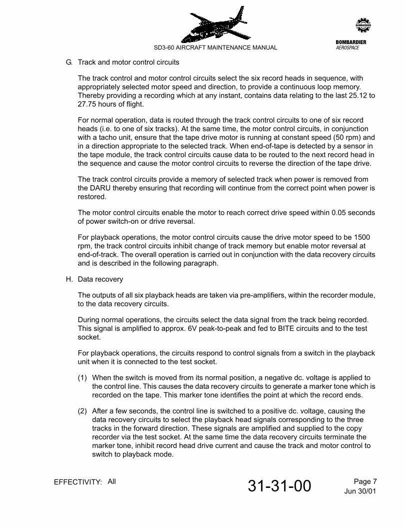
G. Track and motor control circuits
The track control and motor control circuits select the six record heads in sequence, with appropriately selected motor speed and direction, to provide a continuous loop memory. Thereby providing a recording which at any instant, contains data relating to the last 25.12 to 27.75 hours of flight.
For normal operation, data is routed through the track control circuits to one of six record heads (i.e. to one of six tracks). At the same time, the motor control circuits, in conjunction with a tacho unit, ensure that the tape drive motor is running at constant speed (50 rpm) and in a direction appropriate to the selected track. When end-of-tape is detected by a sensor in the tape module, the track control circuits cause data to be routed to the next record head in the sequence and cause the motor control circuits to reverse the direction of the tape drive.
The track control circuits provide a memory of selected track when power is removed from the DARU thereby ensuring that recording will continue from the correct point when power is restored.
The motor control circuits enable the motor to reach correct drive speed within 0.05 seconds of power switch-on or drive reversal.
For playback operations, the motor control circuits cause the drive motor speed to be 1500 rpm, the track control circuits inhibit change of track memory but enable motor reversal at end-of-track. The overall operation is carried out in conjunction with the data recovery circuits and is described in the following paragraph.
H. Data recovery
The outputs of all six playback heads are taken via pre-amplifiers, within the recorder module, to the data recovery circuits.
During normal operations, the circuits select the data signal from the track being recorded. This signal is amplified to approx. 6V peak-to-peak and fed to BITE circuits and to the test socket.
For playback operations, the circuits respond to control signals from a switch in the playback unit when it is connected to the test socket.
(1) When the switch is moved from its normal position, a negative dc. voltage is applied to the control line. This causes the data recovery circuits to generate a marker tone which is recorded on the tape. This marker tone identifies the point at which the record ends.
(2) After a few seconds, the control line is switched to a positive dc. voltage, causing the data recovery circuits to select the playback head signals corresponding to the three tracks in the forward direction. These signals are amplified and supplied to the copy recorder via the test socket. At the same time the data recovery circuits terminate the marker tone, inhibit record head drive current and cause the track and motor control to switch to playback mode.

Jun 30/0131-31-00 Page 8EFFECTIVITY: All
zSD3-60 AIRCRAFT MAINTENANCE MANUAL
(3) Thus the tape will move at high speed in the forward direction and the data from the three tracks recorded in this direction will be played back to the copy recorder.
(4) When the end-of-tape is sensed, the tape direction is reversed and data from the other three playback heads is selected. Copying continues until the opposite end-of-tape is reached, at which time the original tape direction and playback heads are selected. Eventually, the marker tone will be played back and the detection of this by the playback unit causes the control signal to be removed, thereby restoring the system to normal operation i.e. with the recording continuing on the same track and at the same point as before playback.
The playback signals produced at the DARU output are approximately 6V peak-to-peak and are superimposed on dc. levels which, if all three lines are considered, provide a binary coded indication of the track selected by the track control circuits.
3. Self Test
CAUTION: THE OPERATION OF THE SELF TEST FUNCTION CONFIRMS THE RECORDER IS RUNNING. IT DOES NOT CONFIRM CORRECTLY CALIBRATED DATA IS BEING RECORDED.
A. Note that the electrical master switch is set to INTERNAL POWER. If set to EXTERNAL POWER ensure that an external supply is connected.
B. At the flight data entry panel, set the ground check switch to GROUND CHECK and note that the status indicator remains unlit (ignoring any initial display) for approx. 30 seconds.
C. Depress status indicator and check that it illuminates.
D. Set the ground check switch to the unmarked position.
4. Power Supplies
The 115V, 400 HZ supply for the DARU is taken from the left 115V 400 HZ busbar via a one amp circuit breaker No.315 on left distribution panel 1D. The 26V 400 Hz reference supply for the gyro transformer pitch and roll is taken from the right 26V 400 Hz busbar via a further 1 amp circuit breaker No. 351 (panel 2D).
The 28V dc. supply for the airspeed transducer and the accelerometer is taken from the left essential services busbar via a 5 amp circuit breaker (No.32) on distribution panel 1D.

Jun 30/0131-31-00 Page 9EFFECTIVITY: All
zSD3-60 AIRCRAFT MAINTENANCE MANUAL
Flight Data Entry Panel - ControlsFigure 1
Jun 30/0131-31-00 Page 10EFFECTIVITY: All
zSD3-60 AIRCRAFT MAINTENANCE MANUAL
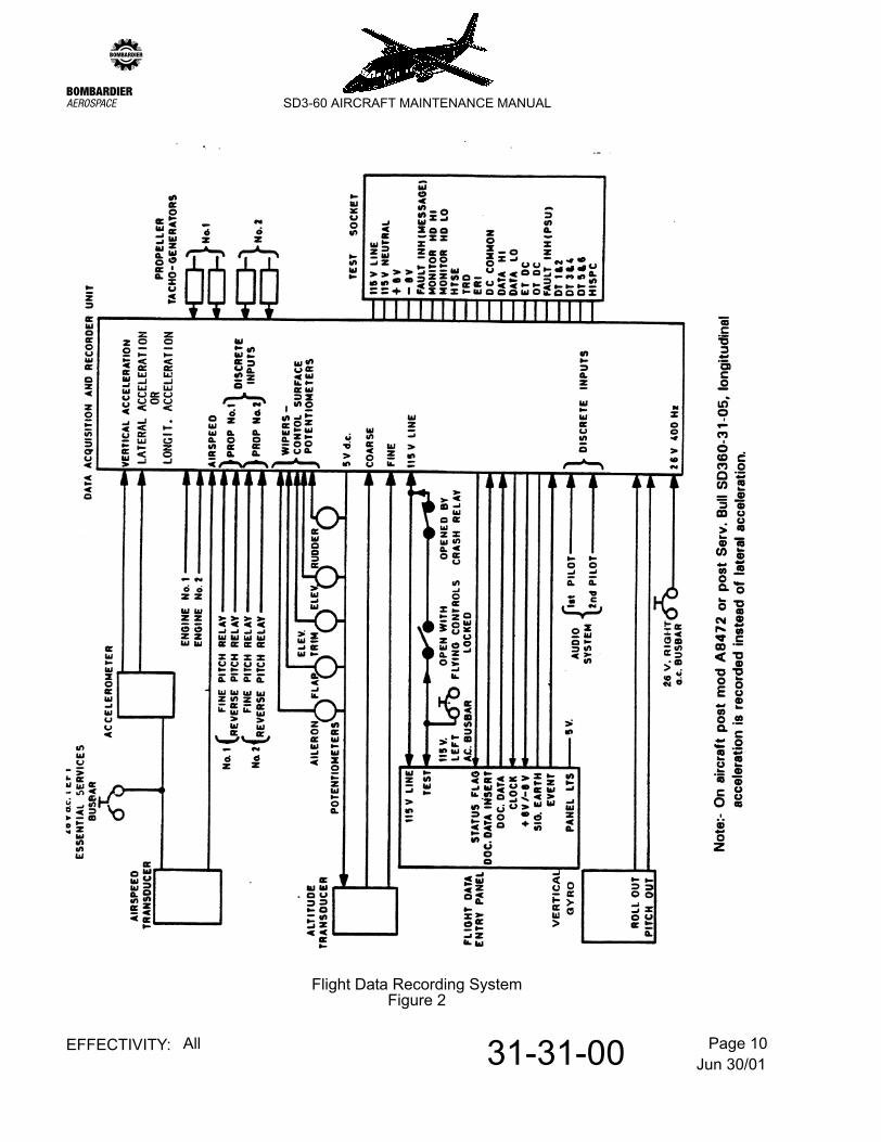
Flight Data Recording SystemFigure 2

Jun 30/0131-31-00 Page 201EFFECTIVITY: All
zSD3-60 AIRCRAFT MAINTENANCE MANUAL
AMM31-31-00 2.0.0.0FLIGHT DATA RECORDING SYSTEM - MAINTENANCE PRACTICES
1. Adjustment/Test
A. Power Checks
NOTE: For read-out checks - refer to para D.
The following abbreviations are used in the text:-
FDEP - Flight Data Entry Panel
DARU - Data Acquisition and Recorder Unit.
(1) Refer to 12-09-03, pb301. Energise the 28V DC Left Essential Services Busbar, the 26V AC Right Busbar and the 115V AC Left and Right Busbars.
(2) Set the GUST LOCK CONTROL LEVER to the UNLOCKED position.
(3) Ensure that the inertia switch is set on line i.e. voice recorder power on and 'RECORDER POWER OFF WARNING' lamp unlit.
(4) Reset C/B No.315 on panel 1D.
(5) Ensure that C/B Nos.178 and 192 on panel 2D are open.
(6) Ensure that 115V, 400Hz power is present at DARU PL2 pin 1 and F.D.E.P pins X and Y.
(7) Reset C/B No.351 on panel 2D.
(8) Ensure that 26V, 400Hz power is present at D.A.R.U. PL1 pins 11 and 29.
(9) Ensure that C/B Nos. 32, 315 and 351 are reset.
(10) Ensure that there is no electrical power present on or between any DARU connector pins except for the following:-
(a) PL1
(b) PL2
Between pins 31 and 32 less than 2V DCBetween pins 33 and 34 less than 3V DC
Pin 1 115V ACPin 11 26V ACPin 29 26V ACBetween pins 25 and 27 approximately 0V

Jun 30/0131-31-00 Page 202EFFECTIVITY: All
zSD3-60 AIRCRAFT MAINTENANCE MANUAL
(11) Reset C/B Nos.361, 362 and 363 and 371 on distribution panel 2D.
(12) Check FDEP panel lighting by operating No.2 Pilots GENERAL dimmer switch on panel 1P.
(13) Reset C/B No.32.
(14) Ensure that 28V DC is present on accelerometer pin A only. No voltage should be present on any other pin.
(15) Ensure that 28V DC is present on Air Speed Transducer pin A only. No voltage should be present on any other pin.
B. Calibration checks following a system component change.
(1) When a transducer is replaced, the associated calibration check should be carried out on the appropriate channel - refer to para C.
(2) When a potentiometer is replaced, the associated calibration check should be carried out on the appropriate channel - refer to para C.
(3) When a Data Acquisition and Recorder Unit is replaced, each channel should be tested for serviceability. A full calibration check of a channel is not required unless the sample reading from that channel is found to have deviated outside the accepted tolerance.
For example, a compass angle of 180° should give a counts reading of 512± 5. Therefore, a count of 506 or 518 would be unacceptable and a full calibration check carried out.
(4) When any of the following components are replaced, its associated calibration check should be performed - refer to para. C.
(a) Engine torque transmitter
(b) Tacho-generator
(c) Gyro compass
(5) When an accelerometer is replaced, the associated calibration checks should be carried out - refer to para. C.
C. Calibration Checks
NOTE: (a) In the event of maintenance work being needed, the Flight Data Recorded should be electrically isolated to prevent the accidental erasure of data by tripping C/B Nos.315 and 365 on panels 1D and 2D respectively.
(b) Relevant sections of these checks are to be performed when components in the flight data recording system are changed.
Jun 30/0131-31-00 Page 203EFFECTIVITY: All
zSD3-60 AIRCRAFT MAINTENANCE MANUAL
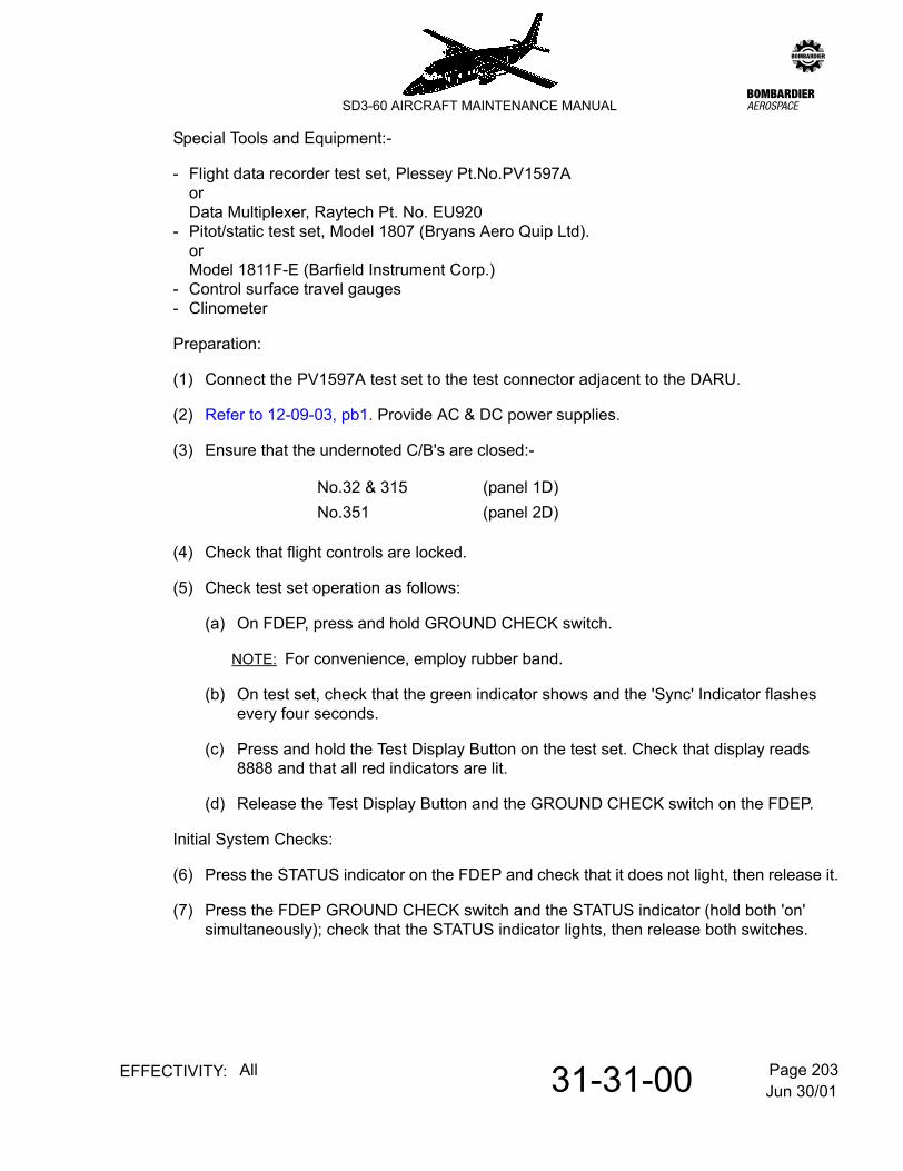
Special Tools and Equipment:-
- Flight data recorder test set, Plessey Pt.No.PV1597AorData Multiplexer, Raytech Pt. No. EU920
- Pitot/static test set, Model 1807 (Bryans Aero Quip Ltd).orModel 1811F-E (Barfield Instrument Corp.)
- Control surface travel gauges- Clinometer
Preparation:
(1) Connect the PV1597A test set to the test connector adjacent to the DARU.
(2) Refer to 12-09-03, pb1. Provide AC & DC power supplies.
(3) Ensure that the undernoted C/B's are closed:-
(4) Check that flight controls are locked.
(5) Check test set operation as follows:
(a) On FDEP, press and hold GROUND CHECK switch.
NOTE: For convenience, employ rubber band.
(b) On test set, check that the green indicator shows and the 'Sync' Indicator flashes every four seconds.
(c) Press and hold the Test Display Button on the test set. Check that display reads 8888 and that all red indicators are lit.
(d) Release the Test Display Button and the GROUND CHECK switch on the FDEP.
Initial System Checks:
(6) Press the STATUS indicator on the FDEP and check that it does not light, then release it.
(7) Press the FDEP GROUND CHECK switch and the STATUS indicator (hold both 'on' simultaneously); check that the STATUS indicator lights, then release both switches.
No.32 & 315 (panel 1D)No.351 (panel 2D)

Jun 30/0131-31-00 Page 204EFFECTIVITY: All
zSD3-60 AIRCRAFT MAINTENANCE MANUAL
(8) Press the FDEP GROUND CHECK switch and check that the STATUS indicator is not lit.
NOTE: During this test the indicator may flash once or twice after initial operation of the GROUND CHECK switch. As long as the indicator does not flash after a period of 30 seconds the system is functioning correctly and ready for subsequently listed calibration checks. If however, the FAULT lamp remains lit continuously any time during the test the DARU should be removed as unserviceable.
(9) Select the following test set switches thus:-
- RATE/FRAME to Position 1.- PARAMETER to 000.- 64/32 to 64.- AD/REC to AD.
(10) Press the GROUND CHECK switch on the FDEP and after eight seconds, check:-
(a) That the 'Sync' lamp on the test set is flashing once every four seconds.
and
(b) That the numerical display reads 905
NOTE: 10 (a) and 10 (b) should apply for as long as the GROUND CHECK switch is depressed. If these conditions do not apply, the DARU is not functioning correctly and should be replaced.
(11) Release the GROUND CHECK switch and UNLOCK the flight controls, then check:-
(a) The 'Sync' lamp on the test set is flashing once every four seconds.
(b) The numerical display reads 905.
(c) The STATUS indicator is not lit.
NOTE: During all subsequent checks, the 'Sync' lamp should flash once every four seconds as long as data is being produced.
Data Entry Panel Checks:
(12) Set test set switches thus:-
- RATE/FRAME to 4- 64/32 to 64- PARAMETER to 060- AD/REC to AD.
(13) In the following sequence (left to right) set the FDEP 'thumbwheel' switches as follows:-
1, 2, 3, 4, 5, 6, 7, 8.

Jun 30/0131-31-00 Page 205EFFECTIVITY: All
zSD3-60 AIRCRAFT MAINTENANCE MANUAL
(14) Check that lamps 1 and 2 on test set are unlit.
(15) Press FDEP EVENT button, holding it on, and check that test set lamp 1 is lit. Release EVENT button and check lamp 1 goes out.
(16) Press the FDEP DDI button and check that test set lamp 2 is lit. Release the button and check that lamp 2 goes out.
(17) Press the DDI button for 1 second and release.
Ensure that lamps 12, 11, 10 and 9 all become lit for approx 32 seconds.
NOTE: After this period, check that lamp 12, 11, 10 and 9 cycle through the sequence:-
NOTE: The lamp sequences will update every four seconds.
(18) Select REC on the AD/REC switch on the test set and repeat (17).
NOTE: There will be a delay of approximately 20 seconds after pressing DDI button before lamps operate.
(19) Reselect AD on the AD/REC switch.
Heading checks:
(20) Check that the aircraft compass system is operating satisfactorily before commencing checks by noting the removal from view of the heading flags on the RMI and on the HSI or EHSI as fitted.
(21) Set the test switches thus:-
- RATE/FRAME to 4- PARAMETER to 010- 64/32 to 64- AD/REC to AD.
Lamp 12 11 10 90 0 0 10 0 1 00 0 1 10 1 0 0 0 is unlit0 1 0 1 1 is lit0 1 1 00 1 1 11 0 0 0

Jun 30/0131-31-00 Page 206EFFECTIVITY: All
zSD3-60 AIRCRAFT MAINTENANCE MANUAL
(22) Set compass to 0° as accurately as possible by rotating aircraft or compass gyro. Check that test set display is:-
- 0000 + 5- 1023 - 5
(23) Set the compass to each of the points in the following table and remain at each point for approximately 5 seconds. Check the test set display at each point and plot a calibration graph of heading versus 'counts' Check for absence of excessive scatter.
Vertical Acceleration:
(24) Set test set switches as follows:-
- RATE to 32- PARAMETER to 001- 64/32 to 64- AD/REC to AD
(25) Check test set display is 480 ± 20 counts.
NOTE: 1g theoretical reading is 0478, with changes of 110 counts per g.
Lateral Acceleration: (pre Serv.Bull.SD360-31-05)
(26) Set test set switches as follows:
- RATE to 16- PARAMETER to 012
(27) Check test set displays 0532 ± 20 counts.
NOTE: Zero g reading is 0532, with changes of 110 counts per g.
Compass Angle Test Set Display
45° 128 ± 590° 256 ± 5135° 384 ± 5180° 512 ± 5225° 640 ± 5270° 768 ± 5315° 896 ± 5360° 1023 ± 5
0000 ± 5

Jun 30/0131-31-00 Page 207EFFECTIVITY: All
zSD3-60 AIRCRAFT MAINTENANCE MANUAL
Longitudinal Acceleration: (post mod A8472 or post Serv.Bull.SD360-31-05)
(28) Select the test set switches as follows:-
- RATE/FRAME - 16- PARAMETER - 012
(29) Ensure the test set displays 0532 ± 20 counts.
NOTE: Zero g reading is 0532, with changes of 110 counts per g.
Pitch Attitude:
(30) Unmount the vertical gyro associated with the second pilots flight director
(31) Set test set switches as follows:-
- RATE to 16- PARAMETER to 002
(32) Mount the gyro on a tilt table and adjust for a pitch angle of 0° ± .25°. Check test set display reads 512 ± 8 counts.
(33) Tilt the gyro to the following pitch angles for one minute each:-
- Nose Down: 5° and 12°- Nose Up: 5° and 20°
NOTE: Check that the test set displays between 350 and 600 counts for each change.
Roll Attitude
(34) Plot a calibration chart of angles versus counts and check for reasonable linearity.
(35) Set test set switches as follows:-
- RATE to 8- PARAMETER to 007
(36) Adjust the gyro tilt table for 0° ± .25° roll. Check that the test set displays 512 ± 5 counts.
(37) Adjust the tilt table to the following roll angles for one minute each and for each step, check that the test set displays between 400 and 600 counts:-
Left and Right : 5°, 10°, 15° 20° and 30°.
(38) Plot a calibration graph of angles versus counts and check for reasonable linerity.
(39) Remount the gyro unit.

Jun 30/0131-31-00 Page 208EFFECTIVITY: All
zSD3-60 AIRCRAFT MAINTENANCE MANUAL
Altitude Coarse and Fine:
(40) Connect the pitot/static test set to the aircraft sensors from which the flight recorder transducers are tapped and set to 1030 milli-bars.
(41) Set RATE/FRAME switch on PV1597A test set to 4.
(42) Set up pressure altitudes shown on the following table.
NOTE: (a) At each stage, select PV1597A test set PARAMETER switch to 030 and 040 in turn and read respective test set display counts appropriate to altitude fine and coarse readings.
(b) Allow approximately one minute between each recording.
(43) Plot counts obtained against millibars.
NOTE: Resultant graphs should be reasonably linear.
Indicated Airspeed:
(44) Connect the pitot/static test set to the aircraft sensors from which the flight recorder transducers are tapped (right pitot head and No.2 static vent).
ALTITUDE FINE ALTITUDE COARSE
Pitot Static Set to: PARAMETER 030 PARAMETER 040
mb FEET DISPLAY ± 80 DISPLAY ± 60
1030 -460 244 24980 920 774 77940 2060 795 120880 3850 159 183840 5100 265 226790 6730 795 279750 8090 785 311700 9880 255 374650 11780 276 427600 13800 806 480560 15520 774 523510 17810 224 576460 20290 286 629

Jun 30/0131-31-00 Page 209EFFECTIVITY: All
zSD3-60 AIRCRAFT MAINTENANCE MANUAL
(45) Select the PV1597A test set switches as follows:-
- RATE/FRAME to 4- PARAMETER to 020
(46) Adjust the pitot/static test set to the settings in the following table and record PV1597A test set display counts at each stage.
NOTE: Allow approximately one minute at each point before continuing to next.
(47) Remove pitot/static test set.
(48) Plot calibration graph and check for absence of excessive scatter.
Rudder Position:
(49) Before attempting to calibrate rudder position information, the following actions must be carried out:-
(a) Select the PB1597A test set switches to:-
- RATE/FRAME to 16- PARAMETER to 003
(b) Hold the FDEP GROUND CHECK switch down (employ rubber band).
(c) Select flight controls LOCKED and centralize rudder pedals to lock the rudder at neutral setting.
(d) Slacken the screws securing the rudder position potentiometer to its mounting bracket.
Pitot/Static Set to:Display
mb kt
0 0 1024 - 140 + 14
12 85.8 100 ± 1424 121.1 190 ± 1436 148.0 281 ± 1648 170.6 374 ± 2060 190.3 467 ± 2272 208.0 558 ± 2484 224.2 648 ± 2696 239.2 740 ± 28
108 253.3 832 ± 30

Jun 30/0131-31-00 Page 210EFFECTIVITY: All
zSD3-60 AIRCRAFT MAINTENANCE MANUAL
(e) Rotate the potentiometer until the test set display reads 512 ± 25 counts.
(f) Tighten the securing screws and check that the test set reading has not been altered.
(50) Fit travel gauge to rudder.
(51) Disengage control locks.
(52) Operate rudder to the settings in the following table, noting the angle and test set display each time; allow approximately one minute between each change.
(53) Plot calibration graph and check for absence of excessive scatter.
Aileron Position:
(54) Before attempting to calibrate aileron position information, the following actions must be carried out.
(a) Select the PV2597A test set switches to:-
- RATE/FRAME to 16- PARAMETER to 004
(b) Hold the FDEP GROUND CHECK switch down (employ rubber band.
(c) Select flight controls LOCKED and centralize handwheels to lock ailerons at neutral settings.
(d) Slacken the screws securing the left aileron potentiometer to its mounting bracket.
(e) Rotate the potentiometer until the test set display reads 500 ± 30 counts.
(f) Tighten securing screws and check that the test set display remains unchanged.
(55) Place clinometer centrally on top of the left aileron and adjust to register zero.
Rudder Angle Display
MAX LEFT Between 5 and 1020 counts+20° L
low count atMAX LEFT
+10° L+ 5° L- 5° R-10° R-20° RMAX RIGHT

Jun 30/0131-31-00 Page 211EFFECTIVITY: All
zSD3-60 AIRCRAFT MAINTENANCE MANUAL
(56) Disengage control locks.
(57) Operate the aileron to the settings in the following table, noting the angle and test set display each time; allow approximately one minute between each change.
(58) Plot calibration graph and check for absence of excessive scatter.
Flap Position:
(59) Before attempting to calibrate flap position information, perform the following:-
(a) Provide hydraulic pressure and fully retract the flaps.
(b) Select the PV1597A test set switches to:-
- RATE/FRAME to 8- PARAMETER to 005
(c) Slacken the screws securing the flap potentiometer to its mounting bracket.
(d) Rotate the potentiometer until the test set reads 980 ± 20 counts. Tighten securing screws and check that test set display has not altered.
(60) Connect travel gauge to left or right inner flap and adjust to register 3° down (rigged retracted setting).
(61) Stage extend and retract flaps throughout gated positions.
NOTE: (a) Remain at each setting for approximately one minute.
(b) For each extend stage, apply a 50 1b upward load at trailing edge of travel gauge equipped flap and record:-
1. Travel gauge reading
2. Test set reading
(c) Repeat actions referred in (b) for retact stages.
Aileron Angle Display
MAX DOWN Between 5 and 1020 counts
low counts at max DOWN
- 8°- 5°+10°+16°MAX UP

Jun 30/0131-31-00 Page 212EFFECTIVITY: All
zSD3-60 AIRCRAFT MAINTENANCE MANUAL
(62) Plot calibration graphs for extend and retract angles against test set display counts and check for absence of excessive scatter.
Elevator Position:
(63) Before attempting to calibrate elevator position information, perform the following:-
(a) Select the PV1597A test set switches to:-
- RATE/FRAME to 16- PARAMETER to 013
(b) Hold the FDEP GROUND CHECK switch down (employ rubber band).
(c) Select flight controls at 0° and centralize control columns to lock the elevators at neutral.
(d) Slacken the screws securing the pitch control potentiometer to its mounting bracket.
(e) Rotate the potentiometer until the test set display reads 730 ± 30 counts. Tighten the securing screws, checking that test set reading is maintained.
(64) Attach travel gauge centrally to trailing edge of left or right elevator and adjust to register zero.
(65) Disengage control locks and operate elevators to the settings in the following table, noting the angle and test set display each time; allow approximately one minute between each change
(66) Plot a calibration graph and check for absence of excessive scatter.
Elevator Angle Display
Max Down Between 5 and 1020 counts
low count at MAX UP
5° Down5° Up
10° Up20° Up
Max Up
Jun 30/0131-31-00 Page 213EFFECTIVITY: All
zSD3-60 AIRCRAFT MAINTENANCE MANUAL
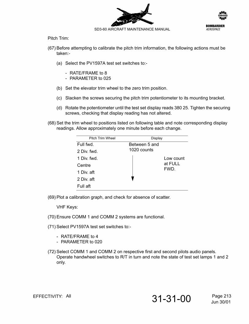
Pitch Trim:
(67) Before attempting to calibrate the pitch trim information, the following actions must be taken:-
(a) Select the PV1597A test set switches to:-
- RATE/FRAME to 8- PARAMETER to 025
(b) Set the elevator trim wheel to the zero trim position.
(c) Slacken the screws securing the pitch trim potentiometer to its mounting bracket.
(d) Rotate the potentiometer until the test set display reads 380 25. Tighten the securing screws, checking that display reading has not altered.
(68) Set the trim wheel to positions listed on following table and note corresponding display readings. Allow approximately one minute before each change.
(69) Plot a calibration graph, and check for absence of scatter.
VHF Keys:
(70) Ensure COMM 1 and COMM 2 systems are functional.
(71) Select PV1597A test set switches to:-
- RATE/FRAME to 4- PARAMETER to 020
(72) Select COMM 1 and COMM 2 on respective first and second pilots audio panels. Operate handwheel switches to R/T in turn and note the state of test set lamps 1 and 2 only.
Pitch Trim Wheel Display
Full fwd. Between 5 and 1020 counts2 Div. fwd.
1 Div. fwd. Low count at FULL FWD.
Centre1 Div. aft2 Div. aftFull aft

Jun 30/0131-31-00 Page 214EFFECTIVITY: All
zSD3-60 AIRCRAFT MAINTENANCE MANUAL
These should operate as shown on following table:-
Parameters requiring an engine run:
Calibrations of engine torque, propeller speed and propeller pitch indications for the No.1 and No.2 engines follow.
NOTE: To avoid unnecessary engine running, it is convenient to calibrate prop RPM, torque and prop pitch during the same run. Prop RPM and torque can be done together whilst the prop pitch lights can be observed when the power levers are moved to change the pitch from FLIGHT FINE to REVERSE. It is important to check that these lights are not flickering when the subsequently referred test lamps on the PV1597A test set are being observed.
No.1 Engine Torque and PRPM:
(73) Select the PV1597A test set switches as follows:-
- RATE/FRAME to 1- PARAMETER to 006
Note the test set display reading (torque zero).
(74) Start the No.1 engine and:-
(a) Set up stabilized PRPM referred on following table and note corresponding test set display counts; allow approximately one minute at each step before proceeding to next.
(b) Select test set switches as follows:-
- RATE/FRAME to 8- PARAMETER to 035
VHF Key State Lamp 2 Lamp 1
Neither 1 1 0 is unlitCOMM 1 0 1 is litCOMM 2 0 1

Jun 30/0131-31-00 Page 215EFFECTIVITY: All
zSD3-60 AIRCRAFT MAINTENANCE MANUAL
(c) Set up stabilized torque settings referred on table and note corresponding test set display counts; again allow approximately one minute at each step.
NOTE: After shutdown, calibration graphs of PRPM and torque against display counts should be prepared and checked for absence of excessive scatter.
No.1 Engine Propeller Pitch Discretes:
(75) Select the PV1597A test set switches as follows:-
- RATE/FRAME to 4- PARAMETER to 010
(76) Progressively operate power lever from FLIGHT IDLE to full REVERSE, checking that the state of test set lamps 1 & 2 (only) conform with the referred states of the pitch indicator lights (see following table).
NOTE: The above operation should be performed three times.
(77) Shutdown engine.
Engine Instruments Display (PRPM) RATE/FRAME to 1 PARAMETER to 006
Display (Torque) RATE/FRAME to 8 PARAMETER to 035PRPM Torque
1000 as obtained 297 ± 8 -1100 as obtained 269 ± 8 -1400 as obtained 213 ± 8 -1600 as obtained 190 ± 8 -
As Req. 1000 - 990 ± 15As Req. 2000 - 955 ± 15As Req. 3000 - 925 ± 15
ON state (Pitch Indicator Lights)
Test Set Lamps
Lamp 2 (Reverse)
Lamp 1 (Fine)
Neither 1 1Blue (Fine) 0 1 0 is unlitBlue & Green (reverse)
0 0 1 is lit

Jun 30/0131-31-00 Page 216EFFECTIVITY: All
zSD3-60 AIRCRAFT MAINTENANCE MANUAL
No.2 Engine Torque and PRPM:
(78) Select the PV1597A test set switches as follows:-
- RATE/FRAME to 1- PARAMETER to 046
Note the test set display reading (torque zero).
(79) Start the No.2 engine and:-
(a) Set up stabilized PRPM referred on following table and note corresponding test set display counts; allow approximately one minute at each step before proceeding to next.
(b) Select test set switches as follows:-
- RATE/FRAME to 078- PARAMETER to 017
(c) Set up stabilized torque settings referred on table and note corresponding test set display counts; again allow approximately one minute at each step.
NOTE: After shutdown, calibration graphs of PRPM and torque against display counts should be prepared and checked for absence of excessive scatter.
No.2 Engine Propeller Pitch Discretes:
(80) Select the PV1597A test set switches as follows:-
- RATE/FRAME to 4- PARAMETER to 014
Engine Instruments Display (PRPM) RATE/FRAME to 1 PARAMETER to 046
Display (Torque RATE/FRAME TO 078 PARAMETER to 017PRPM Torque
1000 as obtained 297 ± 8 -1100 as obtained 269 ± 8 -1400 as obtained 213 ± 8 -1600 as obtained 190 ± 8 -
as req. 1000 - 990 ± 15as req. 2000 - 955 ± 15as req. 3000 - 925 ± 15
Jun 30/0131-31-00 Page 217EFFECTIVITY: All
zSD3-60 AIRCRAFT MAINTENANCE MANUAL
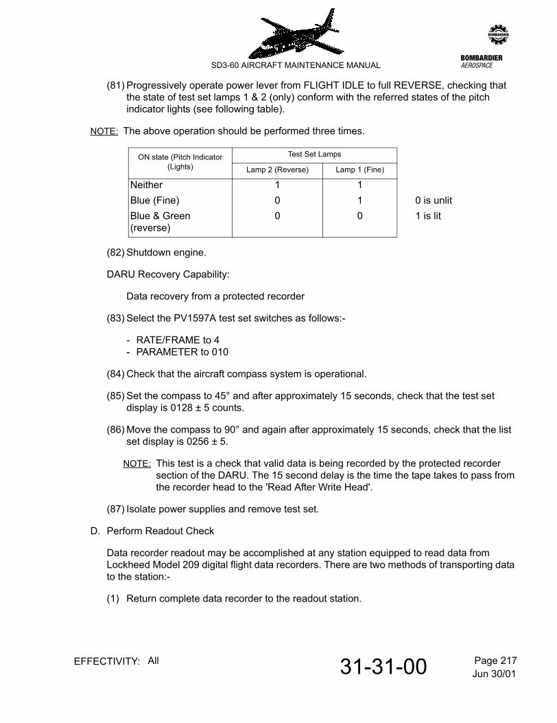
(81) Progressively operate power lever from FLIGHT IDLE to full REVERSE, checking that the state of test set lamps 1 & 2 (only) conform with the referred states of the pitch indicator lights (see following table).
NOTE: The above operation should be performed three times.
(82) Shutdown engine.
DARU Recovery Capability:
Data recovery from a protected recorder
(83) Select the PV1597A test set switches as follows:-
- RATE/FRAME to 4- PARAMETER to 010
(84) Check that the aircraft compass system is operational.
(85) Set the compass to 45° and after approximately 15 seconds, check that the test set display is 0128 ± 5 counts.
(86) Move the compass to 90° and again after approximately 15 seconds, check that the list set display is 0256 ± 5.
NOTE: This test is a check that valid data is being recorded by the protected recorder section of the DARU. The 15 second delay is the time the tape takes to pass from the recorder head to the 'Read After Write Head'.
(87) Isolate power supplies and remove test set.
D. Perform Readout Check
Data recorder readout may be accomplished at any station equipped to read data from Lockheed Model 209 digital flight data recorders. There are two methods of transporting data to the station:-
(1) Return complete data recorder to the readout station.
ON state (Pitch Indicator (Lights)
Test Set Lamps
Lamp 2 (Reverse) Lamp 1 (Fine)
Neither 1 1Blue (Fine) 0 1 0 is unlitBlue & Green (reverse)
0 0 1 is lit

Jun 30/0131-31-00 Page 218EFFECTIVITY: All
zSD3-60 AIRCRAFT MAINTENANCE MANUAL
(2) Use Lockheed Model 235 copy recorder to dump recording from the aircraft onto a reel of copy tape. This reel alone is returned to the readout station thus allowing the recorder to remain in service. The copy recorder is connected to the data dump socket which is located adjacent to the recorder in the rear luggage compartment. It is operated in accordance with the relevant manufacturers instructions.
The readout station provides data in the form of photographic paper traces with appropriate 'counts' scales. Used in conjunction with recorder calibration graphs, flight data (actual speed, height angles etc.) can be determined. It is important that all channels are operating.

Jun 30/0131-31-01 Page 201EFFECTIVITY: All
zSD3-60 AIRCRAFT MAINTENANCE MANUAL
AMM31-31-01 3.0.0.0UNDERWATER LOCATOR BEACON - MAINTENANCE PRACTICES(TYPE N15F210B OR DK100)
1. General
This section provides details of the servicing (battery replacement) and function testing of the subject unit which is essentially an underwater acoustic pulse generator employed to locate the flight recorder in a 'lost-in-water' situation. The battery in Type N15F210B can be replaced as defined below. The Type DK100 is factory sealed and should be returned to the manufacturer for battery replacement.
2. Servicing (Type N15F210B only)
A. Remove and replace battery.
(1) Refer to 6-30-00, pb1. Remove panel 312TZ to gain access to the beacon which is attached to the flight recorder.
(2) Remove beacon from its mounting by performing the following:-
(a) Remove safety wire from three socket head caps. Refer to Figure 201.
(b) Remove the three socket panel cap screws and securing plate.
(c) Remove the Beacon from mounting cradle.
(3) Secure the beacon with Vice-Clamp P/N 810-546, if available, or grasp the body of the
NOTE: Do not clamp the beacon in a vice, except in the approved vice-clamp.
(4) Using spanner wrench P/N 810-235, remove end cover marked 'BATTERY ACCESS' by unscrewing anti-clockwise.
NOTE: Spanner wrench should be held firmly in contact with battery end cap.
(5) Remove shock cushion 810-419 from battery end of beacon if not removed with end cap. Refer to Figure 202.
(6) Tap the body in your hand to remove old battery, and shock cushion 810-371. If the shock cushion is 2 inches wide trim down to 1 13/16 inches.
(7) Insert shock cushion into beacon ensuring that it has reached the bottom.
(8) Pull back each of the two outer corners with tweezers, then apply one drop of Duco cement, or equivalent, under each outer corner.
(9) Press the corners down against the inner surface of the beacon case. Allow at least 20 minutes of drying time.

Jun 30/0131-31-01 Page 202EFFECTIVITY: All
zSD3-60 AIRCRAFT MAINTENANCE MANUAL
(10) Install new battery. If battery is without collar, ensure the end marked 'INSERT THIS END' goes in first as indicated by the arrows.
CAUTION: INSTALLING BATTERY WITH INCORRECT POLARITY WILL CAUSE PERMANENT DAMAGE TO THE BEACON. EVEN TEMPORARY INCORRECT POLARITY CAN CAUSE SUBSEQUENT EXCESSIVE CAPACITOR LEAKAGE WHICH MAY RESULT IN A NEW BATTERY BEING DEPLETED WITHIN A FEW DAYS.
WARNING: INCORRECT BATTERY POLARITY IS PRACTICALLY A SHORT CIRCUIT ACROSS THE BATTERY. IN SOME CASES THIS CAN CAUSE THE BATTERY TO EXPLODE.
(11) Refer to Figure 203. Connect test leads as shown and check for current leakage between battery and beacon body leakage should be less than 2 micro amperes.
(12) Remove the old O-ring from the cover, do not use a screw driver or sharp tool because of danger of damaging the O-ring groove.
(13) Clean the threads and the O-ring groove in body and cover thoroughly by wiping with solvent.
(14) Apply a thin coating of furnished O-ring lubricant P/N 810-346 or 810-500 to new O-ring, O-ring grooves and threads. Carefully install new O-ring on battery cap.
(15) Position rubber shock cushion over contact spring and on the inside of the battery cap.
(16) Refit the end cap and tighten until the cap flange contacts the body. Use hand force only on the spanner wrench.
(17) Function beacon as detailed in para. 3.
(18) Re-install in mounting cradle. Fit securing plate and wirelock the three socket head screws.
(19) Repeat (17).
(20) Refit panel 312TZ.

Jun 30/0131-31-01 Page 203EFFECTIVITY: All
zSD3-60 AIRCRAFT MAINTENANCE MANUAL
3. Adjustment/test (Type N15F210B & DK100)
A. Function check the beacon.
Special Tools & Equipment:-
Ultrasonic Test Set : T360-31-01
(1) Make following selections on test set:-
(a) INT-EXT swich to INT.
(b) TUNING control to between 35 and 40 KHz and GAIN control clockwise.
NOTE: To check if Test Set is operational, jingle keys, coins or other available ultrasonic noise maker near microphone.
(2) Establish temporary circuit across the beacon water switch by means of a piece of flexible conductor. Tune test set for best audible signal. If signal is not present, perform (a) or (b) as appropriate to beacon type:-
(a) Replace battery in beacon type N15F210B.
(b) Replace beacon assembly, type DK100.
(3) Determine pulse rate by counting pulses for ten seconds and dividing by ten.
NOTE: Pulse rate should be approximately one pulse per second, except for MOD 1 beacons, which have a pulse repetition rate of two per second.
(4) Approximate beacon frequency will be indicated by adjusting the test set TUNING control to zero beat (i.e. between the two audible tones).
(5) Remove temporary circuit from across beacon water switch.

Jun 30/0131-31-01 Page 204EFFECTIVITY: All
zSD3-60 AIRCRAFT MAINTENANCE MANUAL
Beacon to mounting cradleFigure 201

Jun 30/0131-31-01 Page 205EFFECTIVITY: All
zSD3-60 AIRCRAFT MAINTENANCE MANUAL
Battery removal/installation (Type N15F210B)Figure 202

Jun 30/0131-31-01 Page 206EFFECTIVITY: All
zSD3-60 AIRCRAFT MAINTENANCE MANUAL
Current leakage check - battery/beacon bodyFigure 203

Jun 30/0131-50-00 Page 1EFFECTIVITY: All
zSD3-60 AIRCRAFT MAINTENANCE MANUAL
AMM31-50-00 4.0.0.0CENTRAL WARNING SYSTEM - DESCRIPTION & OPERATION
1. Description
A. General
Those aspects of the warning system which are centralized are located at the top centre of panel 1P. Should a fault occur, requiring immediate action the indication is a red illumination behind a caption. Other indications are similarly presented with amber illumination.
A TEST/BRT/DIM switch, on panel 11P, will provide selection of two levels of light intensity on all annunciators except the red, which always remains bright. The TEST position of the switch checks the integrity of all the indicating modules on panel 1P and also other warning/indicator lamps in the flight compartment.
Jun 30/0131-50-00 Page 201EFFECTIVITY: All
zSD3-60 AIRCRAFT MAINTENANCE MANUAL
AMM31-50-00 5.0.0.0CENTRAL WARNING SYSTEM - MAINTENANCE PRACTICES
1. Adjustment/Test
A. Test filament integrity of Central Warning System.
(1) Refer to 12-09-03, pb301. Provide electrical power.
(2) Check that all 1P panel warning/indicator annunciators and other flight compartment warning/indicator lights are not illuminated. Trip any associated system circuit breakers necessary to achieve this.
(3) Select TEST on the TEST/BRT/DIM switch on panel 11P and ensure that all annunciators and warning lights in Wiring Manual 31-50-00 are lit and bright.
NOTE: Two filaments connected in parallel, are employed to illuminate panel 1P annunciators. Failure of a filament will be immediately apparent.
(4) Select the switches to DIM and then to BRIGHT and ensure that no warnings/indications are lit.
(5) Return the aircraft to the unpowered state.