31313 31314 16K S 5TH WHEEL INSTALLATION...
20
All Products limited to Vehicle Tow Rating; see Vehicle Owners Manual 9/12/2009 See www.huskytow.com for Warranty Information / Tech Support 1 of 20 Assembly, Installation, Operation and Maintenance Instructions 16K S 5th Wheel Hitch Part # 31313 (Hitch Head and Cross Member) Part # 31314 (2 Uprights) Dealer / Installer: Provide a copy of these Instructions to the end user of this product. These Instructions provide important operating and safety information for proper usage of this product. Demonstrate the proper use of the product with the end user. Have the end user demonstrate that they understand the proper use of the product. End User: Read and follow all instructions included in this manual. Ask your Dealer / Installer for assistance if you do not understand the proper use of the product. Never remove any decals from the product. NOTICE Husky recommends to always drive the king pin into the hitch throat and not drop the king pin from above into the hitch head to avoid incorrect hook-ups. Please read Operating Instruction to understand how this important Safety Feature operates. WARNING Failure to follow all of these instructions may result in death or serious injury Base Rails Not Included.
Transcript of 31313 31314 16K S 5TH WHEEL INSTALLATION...

All Products limited to Vehicle Tow Rating; see Vehicle Owners Manual 9/12/2009 See www.huskytow.com for Warranty Information / Tech Support
1 of 20
Assembly, Installation, Operation and Maintenance Instructions
16K S 5th Wheel Hitch Part # 31313 (Hitch Head and Cross Member) Part # 31314 (2 Uprights)
Dealer / Installer: Provide a copy of these Instructions to the end user of this product. These Instructions provide important operating and safety information for proper usage of this product. Demonstrate the proper use of the product with the end user. Have the end user demonstrate that they understand the proper use of the product.
End User: Read and follow all instructions included in this manual. Ask your Dealer / Installer for assistance if you do not understand the proper use of the product. Never remove any decals from the product.
NOTICE Husky recommends to always drive the king pin into the hitch throat and not drop the king pin from above into the hitch head to avoid incorrect hook-ups. Please read Operating Instruction to understand how this important Safety Feature operates.
WARNING Failure to follow all of these instructions may result in death or serious injury
Base Rails Not Included.

All Products limited to Vehicle Tow Rating; see Vehicle Owners Manual 9/12/2009 See www.huskytow.com for Warranty Information / Tech Support
2 of 20
Contents Assembly, Installation, Operation and Maintenance Instructions ................................................................................ 1 16K S 5th Wheel Hitch................................................................................................................................................. 1 Contents ........................................................................................................................................................................ 2 Introduction .................................................................................................................................................................. 3 Tools Listing................................................................................................................................................................. 3 Package Contents ................................................................................................................................................... 3
Box 1 Contains: ................................................................................................................................................ 3 Box 2 Contains: ................................................................................................................................................ 3
Prior To Installation.............................................................................................................................................. 4 Assembly & Installation Procedures ............................................................................................................. 5
1. Hitch Assembly........................................................................................................................................... 5 2 . Hitch Handle A s s e m b l y .......................................................................................................................... 7
Understanding The Safety Features Of your New HUSKY 5th Wheel. .............................................. 8 Operating Instructions............................................................................................................................................. 10
About Your Husky 16K S............................................................................................................................... 10 Preparing For First Use................................................................................................................................... 10 Uncoupling Your Trailer ................................................................................................................................ 12
Maintenance .......................................................................................................................................................... 12 Towing Tips................................................................................................................................................................ 13
Driving Tow Vehicle ...................................................................................................................................... 13 Driving Conditions ......................................................................................................................................... 13 Check Your Equipment .................................................................................................................................. 13 Trailer Loading ............................................................................................................................................... 13 Tire Inflation ................................................................................................................................................... 13 Towing Vehicle And Trailer Manufacturers Recommendations.................................................................... 14 Passengers In Trailers ..................................................................................................................................... 14 Trailer Lights, Turn Signals, Electric Brakes ................................................................................................. 14
Trouble Shooting.................................................................................................................................................. 15 Warranty Terms:................................................................................................................................................... 17 Parts Listing ................................................................................................................................................................ 18 Appendix A.............................................................................................................................................................. 19
Weighing Truck and 5th Wheel Trailer......................................................................................................... 19 Summarizing Weighing ......................................................................................................................................... 20

All Products limited to Vehicle Tow Rating; see Vehicle Owners Manual 9/12/2009 See www.huskytow.com for Warranty Information / Tech Support
3 of 20
Introduction
• Safety is of paramount importance in both installation and use of the Husky 16K S Hitch System. Observe all "Cautions" and "Notes" found in this manual, as well as common sense precautions to ensure the safety of yourself and others.
• Caution: The Husky 16K S is recommended for use only in truck beds 6 feet or longer. A Husky EZ Roller combined with a 16K S Hitch is recommended for short bed truck of less than 8 ft but longer than 6 ft.
• For best results, it is recommended you have your Husky 16K S system (31313 and 31314) professionally installed by a qualified technician.
• The Husky 16K S 5th Wheel Hitch System is designed to tow 5th Wheel Trailers with a total Gross Vehicle Weight Rating up to 16,000 lbs. do not exceed the rated capacity.
• King pin weight should never exceed 4,000 lbs.
Tools Listing
The following tools will be required for installation: • (2) 7/16” wrenches/sockets • (2) ¾” wrenches/sockets • Eye protection • Gloves • Torque wrench capable of 100 ft-lbs of torque
Package Contents Unpacking: The Husky 16K S system (31313 and 31314) Hitch Assembly ships in two boxes as indicated below. The Husky 16K S (31313 and 31314) does not include Base Rails. Inspect all parts for - damage & verify that all items listed are present.
Box 1 Contains: Hitch head (Qty 1) Hitch Handle w\Grip (Qty 1) Cross Member (Qty 1) Hardware kit
Box 2 Contains: Uprights (Qty 2)

All Products limited to Vehicle Tow Rating; see Vehicle Owners Manual 9/12/2009 See www.huskytow.com for Warranty Information / Tech Support
4 of 20
Prior To Installation
If towing with a short bed truck (less than 8ft but longer than 6ft.) Husky Towing recommend the use of a Husky EZ Roller for increased turning clearance at slow maneuvering speeds.
WARNINGS
• Check the Truck Payload and Trailer Weight as defined in Appendix A (Checking Truck & 5th Wheel Trailer Weight Rating). Never Overload Truck, Trailer or Hitch.
• This Hitch requires Pre-Installed Base Rails which are bolted through the Bed of the Truck into brackets which in turn are fastened to the Truck Chassis. DO NOT INSTALL HITCH BY FASTENING TO THE FLOOR OF THE PICKUP BOX. The Pickup Box Floor is not strong enough to carry the loads imposed by the trailer
• This 5th Wheel Hitch is rated for a MAXIMUM Pin Weight of 4,000 lbs and a MAXIMUM Trailer GVW of 16,000 lbs. Exceeding Maximum ratings may result in death, serious injury or property damage.
The distance from the back of the truck cab to the center of the King Pin (Dim X) should be 4” greater than one-half the trailer width (Dim Y)
Do Not Install this 5th Wheel Hitch in a Pickup truck that has a bed shorter than 6ft. The result of towing with this combination of short bed and 5th Wheel Hitch could be damage to the truck and/or trailer, Serious Injury or Death.
WARNING

All Products limited to Vehicle Tow Rating; see Vehicle Owners Manual 9/12/2009 See www.huskytow.com for Warranty Information / Tech Support
5 of 20
Assembly & Installation Procedures
1. Hitch Assembly
a) If using pre-existing base rails ensure that the center to center (fore and aft) distance is 22” and that there are two pairs of slots in the base rails that are 20 5/8” apart (side to side). Otherwise contact your local dealer for proper base rail selection and installation.
b) Place the uprights into the base rails with the decals facing the rear of the truck. Secure the uprights to the
base rails using the 1 / 2 inch diameter rail pins and secure using the large hairclips in the hardware bag.
c) With the Warning Label of the cross member facing to the driver side of the truck, slide the cross member
assembly downward over the uprights. Determine the mounting holes to obtain the proper height of the hitch head, and from the inside insert the four 1/2" diameter bolts into the appropriate cross member mounting holes and thru each body side. Note: inserting the bolts from the inside will put the lock nuts on the outside of the cross member, this will ensure that the proper torque will be applied to the lock nuts.

All Products limited to Vehicle Tow Rating; see Vehicle Owners Manual 9/12/2009 See www.huskytow.com for Warranty Information / Tech Support
6 of 20
d) Shims 30703 are provided to adjust crossmember and uprights. Use only if necessary for alignment.
e) NOTE: See page 10 for complete height adjusting instructions.
IMPORTANT: The ideal centerline location of the 5thWheel Hitch should be positioned between 1” and 3” forward of the Center of the Rear Axle once installed in the base rails. This position may be limited by your specific base rail installation. Always verify this information before towing down the road and also confirm that you will have adequate turning clearance between the back of the truck cab and the nose of the 5th wheel trailer.
Torque lock nuts to 75 ft. lbs.
Shim 30703
Crossmember
Upright Place shim on either
side as needed

All Products limited to Vehicle Tow Rating; see Vehicle Owners Manual 9/12/2009 See www.huskytow.com for Warranty Information / Tech Support
7 of 20
Hitch Handle Assembly
a. Place the hitch head onto the adjustable cross member and secure with the supplied 3/8" clevis pins and hair pins. Check for freedom of movement.
b. Rotate the handle shaft while pulling it straight out, once the shaft starts sliding out of the guide tube pull it all the way out to lock the hitch head in the open position.
c. Hold the handle with the grip pointed upward and slide the handle onto the handle shaft.
d. Fasten the hitch handle using the supplied ¼-20 HEX HEAD BOLT and ¼-20 NYLON LOCK NUT. Tighten lock nut until it comes in contact with the tube.
e. Use a wrench to trip the lock mechanism to close the hitch head. Be careful to keep your body away
from any moving parts. The handle should rotate and point down towards the bed of the pickup truck.
Trip lock mechanism
HANDLE SHAFT
GUIDE TUBE

All Products limited to Vehicle Tow Rating; see Vehicle Owners Manual 9/12/2009 See www.huskytow.com for Warranty Information / Tech Support
8 of 20
f. View of final assembly of 16K S 5th Wheel System.
g. Rotate the handle straight up and pull out until it is in the locked open position.
Understanding The Safety Features Of your New HUSKY 5th Wheel.
The HUSKY 16K S 5th wheel hitch comes standard with a visual aid to indicate what the current status is of the king pin locking mechanism. Note that the view shown directly below has a red indicator sleeve on the handle shaft. This is intended to give a quick visual aid as to whether the hitch head is closed or open, in the two pictures below it is open. Cross member, uprights and base rails removed for clarity.
There is another visual aid that indicates if the hitch head is closed and locked. This is shown in the picture below with a green shaft that protrudes from the side of the hitch head. If the king pin has been correctly installed into the mouth of the hitch head the slide bar will close, the red indicating sleeve will disappear and the green indicator pin will protrude out as shown below. Cross member, uprights and base rails removed for clarity.
RED INDICATOR SLEEVE RED INDICATOR
SLEEVE
All Products limited to Vehicle Tow Rating; see Vehicle Owners Manual 9/12/2009 See www.huskytow.com for Warranty Information / Tech Support
9 of 20
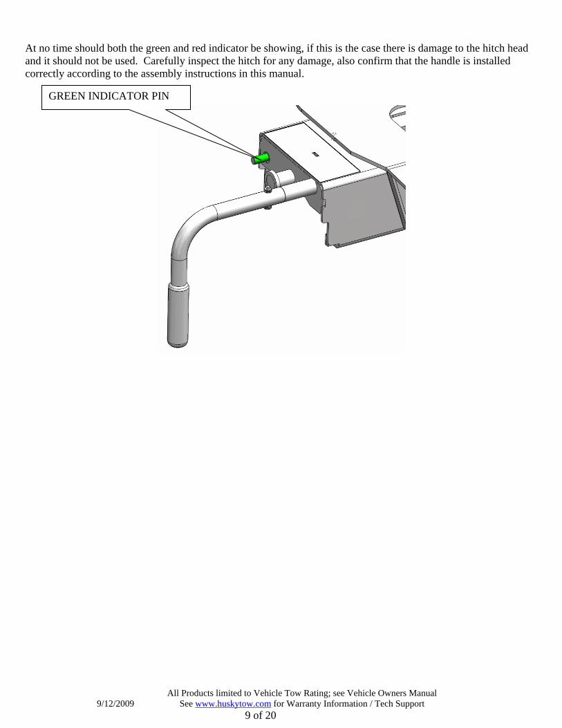
At no time should both the green and red indicator be showing, if this is the case there is damage to the hitch head and it should not be used. Carefully inspect the hitch for any damage, also confirm that the handle is installed correctly according to the assembly instructions in this manual.
GREEN INDICATOR PIN
All Products limited to Vehicle Tow Rating; see Vehicle Owners Manual 9/12/2009 See www.huskytow.com for Warranty Information / Tech Support
10 of 20
Operating Instructions About Your Husky 16K S The Husky 16K S 5th Wheel Hitch System is designed to tow 5th Wheel Trailers with a Gross Vehicle Weight Rating up to 16,000 lbs. Do not exceed the rated capacity as it will create an unsafe towing condition. It has a 4-way swivel head, its height is adjustable from 14 to 17 inches in one-inch increments, and is removed from the bed of the truck by pulling 4 rail pins.
Preparing For First Use Your Husky 16K S 5th wheel system is now installed and you're anxious to be on your way down the road. You're almost there, but take a few minutes to ensure your hitch is set up properly for your particular truck/coach combination by following the steps below.
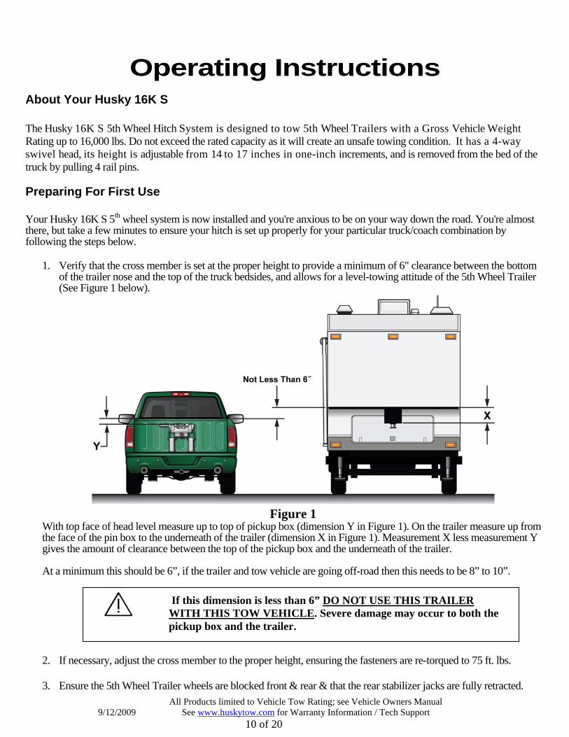
1. Verify that the cross member is set at the proper height to provide a minimum of 6" clearance between the bottom of the trailer nose and the top of the truck bedsides, and allows for a level-towing attitude of the 5th Wheel Trailer (See Figure 1 below).
Figure 1 With top face of head level measure up to top of pickup box (dimension Y in Figure 1). On the trailer measure up from the face of the pin box to the underneath of the trailer (dimension X in Figure 1). Measurement X less measurement Y gives the amount of clearance between the top of the pickup box and the underneath of the trailer. At a minimum this should be 6”, if the trailer and tow vehicle are going off-road then this needs to be 8” to 10”.
2. If necessary, adjust the cross member to the proper height, ensuring the fasteners are re-torqued to 75 ft. lbs. 3. Ensure the 5th Wheel Trailer wheels are blocked front & rear & that the rear stabilizer jacks are fully retracted.
If this dimension is less than 6” DO NOT USE THIS TRAILER WITH THIS TOW VEHICLE. Severe damage may occur to both the pickup box and the trailer.

All Products limited to Vehicle Tow Rating; see Vehicle Owners Manual 9/12/2009 See www.huskytow.com for Warranty Information / Tech Support
11 of 20
4. Also make sure the 5th Wheel Trailer landing leg feet are on a stable surface.
5. With hitch head level, set trailer king pin box ½” to 1” below hitch so trailer will ride up and onto hitch. Back Up the truck under the trailer so the king pin enters the hitch.
6. Rotate the handle of the hitch 180 degrees so that the handgrip is pointing straight up & pull the handle out until the slide bar is held open by the king pin trip mechanism. The handle shaft has a red indicating sleeve to provide a quick visual reference that the handle is not closed. You should also note that the green indicator pin is not protruding from the side of the hitch head.
7. Slowly back the truck so that the bottom plate of the king pin box slides onto the 5th wheel plate & the king pin slides fully into the throat of the hitch head. Set the parking brake of the truck & place the transmission into park.
8. Visually verify the slide bar has closed behind the king pin and the king pin box is resting on the 5th wheel plate. Positively lock the slide bar by rotating the handle clockwise so the handgrip is pointing straight down at the bed of the truck. The red indicator sleeve on the handle shaft should not be visible when correctly hitched up and the green indicator shaft should be protruding from the side of the hitch head.
9. Warning! Never back the tow vehicle under the trailer king pin and then lower the king pin into the hitch. This will result in high pinning and will result in hitch damage and possible vehicle damage, injury or death!
10. Before towing perform a tug test as follows: Ensure the landing gear of the 5th Wheel Trailer are
NEVER LOWER THE KING PIN INTO THE HITCH USING THE TRAILER JACKS. THIS IS A VERY DANGEROUS PRACTICE AND WILL RESULT IN THE KING PIN SITTING ON TOP OF HITCH INSTEAD OF INSIDE. THE TRAILER COULD THEN BECOME DETACHED FROM THE TRUCK DURING TOWING CAUSING SERIOUS DAMAGE AND POSSIBLY INJURY OR DEATH.

All Products limited to Vehicle Tow Rating; see Vehicle Owners Manual 9/12/2009 See www.huskytow.com for Warranty Information / Tech Support
12 of 20
extended to the ground, chock the tires, and attach the electrical & breakaway connectors to the proper receptacles in accordance with your 5th Wheel Trailer owner's manual. Then apply the trailer brakes, and slowly try to pull the trailer forward. The trailer should prevent the truck from moving.
11. Remove the blocks from the wheels of the 5th Wheel Trailer; fully retract the trailer jacks and double check that
the hitch is properly attached to your tow vehicle.
Uncoupling Your Trailer
1. Block your 5th Wheel Trailer wheels front & rear.
2. If necessary, start your truck & back up against the king pin to relieve pressure on the slide bar. Set the parking brake, put the transmission into park and then turn off your vehicle.
3. Extend the landing gear of the 5th Wheel Trailer until the weight of the 5th Wheel Trailer is just off of the 5th wheel plate of the hitch. Do not exceed 1/16" gap between the bottom plate of the king pin box and the tabletop of the hitch. Caution: Raising the 5th Wheel Trailer too high while still connected can damage the hitch head as well as components of your 5th Wheel Trailer. Do not extend the rear stabilizers of the 5th Wheel Trailer prior to or during uncoupling.
4. Disconnect the electrical and breakaway connectors in accordance with your 5th Wheel Trailer owner's manual. With the rubber grip of the handle pointing straight down towards the bed of the truck, pull it straight out and then rotate it straight up to lock the handle in the out position.
5. You are now ready to pull your truck slowly away from the 5th Wheel Trailer.
Maintenance 1. After coupling, always visually check that the slide bar has closed completely across the rear of the king
pin and that the red indicator sleeve on the handle shaft is not showing. Also confirm that the green indicating pin is “popped out” from the side of the hitch head. IMPORTANT! Both indicating features should never both be showing when you are done hitching up for travel.
2. After the first 100 miles, and at least once a year thereafter, inspect all bolts for proper tightness. Retighten nuts if needed. All fasteners ½” diameter, torque to 75 ft-lbs.
3. Once or twice a week when traveling, apply a few drops of lubricant to the top of the pivot pin collar. The pivot pins hold the tabletop or "horseshoe" in place on the hitch head and can be found by locating the hex head bolts on the front and rear of the hitch head.
4. Once or twice a year, apply a light coating of wheel bearing grease to the surfaces of the slide bar that holds the king pin in place. For best results, apply the grease with the slide bar in the closed position. Caution: The slide bar can close with heavy force. Use extreme care to keep fingers, hands, extremities &
WARNING DO NOT TRIP THE HITCH MECHANISM BY HAND AS THIS CAN RESULT IN INJURY . IN NORMAL OPERATION LEAVE THE HITCH OPEN UNLESS IT IS
COUPLED TO A TRAILER. ALWAYS PULL ON THE HANDLE TO OPEN THE HITCH BEFORE COUPLING THE
TRAILER.

All Products limited to Vehicle Tow Rating; see Vehicle Owners Manual 9/12/2009 See www.huskytow.com for Warranty Information / Tech Support
13 of 20
clothing out of the path of the slide bar. Failure to do so could result in severe injury. 5. Periodically inspect your Husky 16K S for wear or damage. If excessive wear or damage is found, contact
your installing dealer or HUSKY technical support staff at www.huskytow.com or 1-877-544-4449.
6. Husky Towing Products recommends the use of a lube disc, contact your local Husky dealer to purchase one.
Towing Tips Driving Tow Vehicle Good habits for normal driving need extra emphasis when towing a trailer. The additional weight of the trailer affects acceleration and braking. Extra time should be allowed for passing, stopping and changing lanes. Signal well in advance of a maneuver to let other drivers know your intentions. Severe bumps and badly undulating roads can damage your towing vehicle, hitch and trailer, and should be negotiated at a slow, steady speed. If any part of your towing system “bottoms out” or if you suspect damage may have occurred in any other way, pull over and make a thorough inspection. Correct any problems before resuming travel. Turning and backing up present new problems; plan ahead. Towing a trailer will change your turning radius, the longer the trailer the larger radius turn.
Driving Conditions When driving in conditions where the pavement is wet, icy, snowy, loose gravel, grass and dirt, reduce speed and do not make any sudden maneuvers. Allow ample distance/time for stopping and changing lanes. If possible, wait for road conditions to improve before driving. Follow all state, local and provincial driving and towing laws in the location you are driving in. Not following your tow vehicle, trailer, and Husky instructions/manuals can result in a fatal accident.
Check Your Equipment Please refer to the MAINTENANCE section. Periodically check the condition of all your towing equipment and keep it in top condition.
Trailer Loading Proper trailer loading is very important. Heavy items should be placed close to the floor near the trailer axle centerline. The load should be balanced side to side and firmly secured in the trailer to prevent shifting.
Tire Inflation Unless specified otherwise by the towing vehicle or trailer manufacturer, tires should be inflated to their manufacturer’s towing recommendations.

All Products limited to Vehicle Tow Rating; see Vehicle Owners Manual 9/12/2009 See www.huskytow.com for Warranty Information / Tech Support
14 of 20
Towing Vehicle And Trailer Manufacturers Recommendations Review the owner’s manual for your towing vehicle and trailer for specific recommendations, capacities and requirements.
Passengers In Trailers Husky Towing does not recommend passengers traveling in or on trailers while being towed.
Trailer Lights, Turn Signals, Electric Brakes Always hook up all of the trailer lights, electric brakes and break-away switch connection whenever trailer is being towed. Also periodically check functionality of all lights before towing and repair any problems as needed.

All Products limited to Vehicle Tow Rating; see Vehicle Owners Manual 9/12/2009 See www.huskytow.com for Warranty Information / Tech Support
15 of 20
Trouble Shooting Problem What To Look For Solution
Hitch is not assembled correctly. Refer to Hitch Assembly section for proper assembly instructions.
Base Rails are not parallel with each other.
Use spacer to hold both base rails parallel while loosening and retightening the carriage bolts.
Hitch is difficult to install and remove from the base rails.
Truck bed collapsing around carriage bolts in base rails.
Install proper spacers between the base rail and corrugations. Refer to installation instructions for specific directions.
Incorrect king pin height The king pin plate should be ½” to 1” below the 5th wheel skid plate.
Excessive angle between hitch head and king pin.
Level trailer or tow vehicle with blocks under the wheels.
Lube disc is too thick. Check thickness of lube disc. It should not exceed 3/16”.
Hitch will not hook up to the trailer king pin.
Bent king pin. Contact your local dealer for replacement.
King pin is resting on the locking bar, preventing it from sliding open.
Remove pressure on the locking bar by blocking the trailer wheels in front and behind. With trailer wheels blocked and truck running, place truck in reverse, set the parking brake and then put truck in park and turn off the engine. This should relieve the pressure on the locking bar.
Incorrect king pin height. Trailer is up to high; retract the trailer landing legs to remove tension from slide bar.
Excessive angle between hitch head and king pin.
Level trailer or tow vehicle with blocks under the wheels.
Lube disc is too thick. Check thickness of lube disc. It should not exceed 3/16”.
Hitch is difficult to unhook from trailer.
Bent king pin. Contact your local dealer for replacement.
New hitch head. Contact your local dealer for replacement.
Locking bar is difficult to close or open.
Locking bar is worn. Inspect locking bar for wear or damage. Look for a ridge at the front edge of the locking bar. If found, file away the ridge and lubricate locking bar. Contact the Husky warranty dept. at 1-877-544-4449, or contact your dealer/installer if locking bar is damaged rather than

All Products limited to Vehicle Tow Rating; see Vehicle Owners Manual 9/12/2009 See www.huskytow.com for Warranty Information / Tech Support
16 of 20
worn. Lack of lubrication. Lubricate locking bar and pull
handle with a light coating of grease on all contact surfaces.
Missing spring on trip mechanism. Contact technical support for replacement spring.
Locking bar does not lock into the open position.
Missing or damaged trip mechanism. Inspect trip mechanism. The trip mechanism should not be bent and the spring should be attached and have good tension.
Table top distorted/cracking at the pivot point.
Wear and tear. Replace hitch head, contact technical support.
Green and Red indicator are showing at the same time.
Broken return spring on king pin bar clamp.
Contact technical support for replacement spring.
Handle installed incorrectly. Review assembly instructions to ensure correct installation.
Linkage mechanism is damaged. Turn head upside down and inspect pivot linkage for green indicator pin.

All Products limited to Vehicle Tow Rating; see Vehicle Owners Manual 9/12/2009 See www.huskytow.com for Warranty Information / Tech Support
17 of 20
Warranty Terms: 5-Year Limited Warranty: This warranty applies solely to 5th Wheel and Weight Distribution Hitches manufactured by DTS Manufacturing for Husky Towing Products. DTS Manufacturing, Husky Towing Products and Coast Distribution make no guarantees or warranties for products not manufactured by DTS Manufacturing. Such products are covered solely under any applicable warranty of the manufacturer. It is always recommended that the operating instructions and guarantee instructions provided by the manufacturer are followed. DTS Manufacturing warrants its products to be free from manufacturing and material defects to the original purchaser for the length of warranty stated above from the date of retail purchase. If any products are found to have a manufacturing or material defect, the product will be replaced or repaired at the option of DTS Manufacturing, Husky Towing Products and Coast Distribution with proof of purchase by the original purchaser. The original purchaser shall pay all transportation and shipping costs associated with the return of the defective product and the defective product shall become the property of DTS Manufacturing. The Warranty applies to DTS manufactured products used for individual and recreational purposes. Commercial usage of the DTS manufactured products limits the warranty to 90-days from date of purchase. The Warranty applies only to DTS manufactured products which are found to be defective in manufacturing or material. This warranty does not apply to normal wear and tear of to the finished placed on DTS manufactured products. DTS Manufacturing, Husky Towing Products and Coast Distribution are not responsible for any labor costs incurred for removal or replacement of the defective product. DTS Manufacturing, Husky Towing Products and Coast Distribution are not responsible for repair or replacement of any product under the limited warranty where the product was improperly installed, misapplied, altered, abused, neglected, overloaded, misused or damaged as a result of an accident, including any use of the product not in accordance with all product operating and safety instructions. Any implied warranty of merchantability or fitness for a particular purpose on any DTS Manufactured product shall be limited to one (1) year from the date of purchase at retail to the original purchaser. Some states do not allow limitations on how long an implied warranty lasts, so the above limitation may not apply to you. Without limiting the generality of the foregoing, DTS Manufacturing, Husky Towing Products and Coast Distribution shall under no circumstances be liable for any incidental or consequential loss or damage whatsoever arising out of, or in any way relating to any such breach of warranty or claimed defect in, or non-performance of the products. Some states do not allow the exclusion or limitation of incidental or consequential damages, so the above exclusion or limitation may not apply to you. This limited warranty gives you specific legal rights, and you may also have other rights that vary from state to state.

All Products limited to Vehicle Tow Rating; see Vehicle Owners Manual 9/12/2009 See www.huskytow.com for Warranty Information / Tech Support
18 of 20
Parts Listing
ITEM NO. Description QTY
QTY
QTY
QTY
QTY
QTY
QTY
QTY
1 PIN, 1/2" BASE RAIL 4 - - - - 4 - -2 PIN, 1/2" HAIR 4 - - - - 4 - -3 UPRIGHT 2 2 - - - - - -4 HEX HEAD BOLT, 1/4-20 UNC X 1.375 LG 1 - - 1 1 - - -5 HANDLE 1 - - 1 1 - - -6 NUT, NYLON LOCK, 1/4-20 UNC 1 - - 1 1 - - -7 16K S 5TH WHEEL HEAD ASSEMBLY 1 - - 1 - - - -8 PIN, 3/8" HAIR 2 - - 2 - 2 2 -9 PIN, 3/8" CLEVIS 2 - - 2 - 2 2 -
10 CROSS MEMBER 1 - 1 - - - - -11 WASHER FLAT .531 ID X 1.250 OD X .10 THK, 4 - 4 - - 4 - 412 BOLT, HEX, 1/2-13 UNC X 5 LG 4 - 4 - - 4 - 413 NUT, NYLON LOCK, 1/2-13 UNC 4 - 4 - - 4 - 414 BASE RAIL FOR 5TH WHEEL(NOT INCLUDED) NA NA NA NA NA NA NA NA15 SHIMS ( NOT SHOWN ) - 4 - - - - - -
16K S HEAD AND HANDLE PACKAGECROSS MEMBER PACKAGE
2 UPRIGHTS PACKAGE16K S HEAD AND CROSS MEMBER PACKAGE
3131
3
3131
4
3145
2
3145
3
3145
4
3145
5
CROSS MEMBER HARDWARE KIT16K S HITCH HEAD RETAINING PINS
16K S COMPLETE HARDWARE KITHANDLE KIT
3145
6
3145
8

All Products limited to Vehicle Tow Rating; see Vehicle Owners Manual 9/12/2009 See www.huskytow.com for Warranty Information / Tech Support
19 of 20
Appendix A Weighing Truck and 5th Wheel Trailer.
Weigh the Truck and 5th Wheel on a public weigh scale. Public weigh scales can be found at Some Truck Stops, or they can be located from Yellow pages or on the Internet.
Weigh the Truck and 5th Wheel in 3 stages as shown in the sketch.
Step 1, Weigh the both the Truck and 5th Wheel. This is weight 1; this will give the GCW (Gross Combination Weight) of the Truck and 5th Wheel Trailer. The GCW must not exceed the GCWR (Gross Combination Weight Rating) for the Truck. The GCWR of a truck depends on engine size, transmission, rear axle ratio, tow package and other factors. The manufacturer or dealer will be able to find the GCWR from the VIN (Vehicle Identification Number) of the truck.
Step 2, Drive the front wheels of the truck off the weighing platform. Weigh the rear wheels of the truck and the 5th Wheel Trailer wheels. This is weight 2, Subtract weight 2 from the weight 1; the result is the GAW (Gross Axle Weight) for the front axle of the truck. The GAWR (Gross Axle Weight Rating) for the front axle can be found on the VIN plate on the driver’s side door pillar, the measured front GAW must not exceed the front GAWR on the VIN plate.
Step 3, Drive the rear wheels of the truck off the weighing platform; this should leave only 5th Wheel Axles remaining on the weighing platform. This is weight 3, Subtract weight 3 from the weight 1 and this is the GVW (Gross Vehicle Weight) of the truck. The measured GVW must not exceed the GVWR found on the VIN plate. Subtract weight 3 from weight 2 and this is the measured GAW of the rear axle of the truck, and must not exceed the GAWR of the rear axle found on the VIN plate. Weight 3 is also the GAW of the 5th Wheel; this weight should not exceed the GAWR on the plate on the 5th Wheel.

All Products limited to Vehicle Tow Rating; see Vehicle Owners Manual 9/12/2009 See www.huskytow.com for Warranty Information / Tech Support
20 of 20
Summarizing Weighing GCW (Truck & 5th Wheel Trailer) = weight 1
GAW of front axle (Truck) = weight 1 – weight 2
GVW (Truck) = weight 1 – weight 3
GAW of rear axle (Truck) = weight 2 – weight 3
GAW of axles (5th Wheel Trailer) = weight 3
WARNING!!! EXCEEDING ANY WEIGHT RATING IS HAZARDOUS. OVERLOADING OF TRUCK AND/OR 5th WHEEL TRAILER CAN LEAD TO TIRE FAILURE, BRAKE FADE AND OVERHEATING OF THE TRUCK ENGINE OR TRANSMISSION. OVERLOADED VEHICLES ARE MORE UNSTABLE AND UNPREDICTABLE EVEN IN NORMAL DRIVING CONDITIONS.