3116A-001 MULTI SYSTEM ANALOG TV MODULATOR …file.yizimg.com/363295/2011021412565564.pdf ·...
172
3116A-001 MULTI SYSTEM ANALOG TV MODULATOR INSTRUCTION MANUAL
Transcript of 3116A-001 MULTI SYSTEM ANALOG TV MODULATOR …file.yizimg.com/363295/2011021412565564.pdf ·...

3116A-001
MULTI SYSTEM ANALOG TV MODULATOR
INSTRUCTION MANUAL
3116A
2006.10.06 E2474-A-EN01R4 i
This instruction manual describes important information in order to use this unit safely. Before using this unit, read this document thoroughly. Especially, use this unit after reading over “Caution for Safety” and getting well understanding. Also, keep this manual always by keeping good care in order to allow you to refer at anytime when this unit is used. Eiden is paying careful attention on safe usage of this unit without having any damage or injury on user’s life, body or property. Follow to instructions of this document when this unit is used.
Meaning of WARNING and CAUTION
WARNINGContents imagined possibility to be killed or to be got serious injury, if incorrect handling is made by ignoring this indication, are shown.
CAUTIONContents imagined possibility to be got injury or to be occurred only property damage, if incorrect handling is made by ignoring this indication, are shown.
FOR SAFE USE

3116A
2006.10.06 E2474-A-EN01R4 ii
Abnormal condition is occurred by any chance.
WARNING
Electric Shock
Pull out power cord plug from outlet immediately when abnormal condition is occurred, such as generation of smoke, bad smell or abnormal sound by any chance. In case of smoke generation, ask repair to Eiden after confirming on pulling out of smoke. Repair by user itself is dangerous, so do not do it unconditionally. If unit is keeping to use under abnormal condition, it may be the cause of electric shock or fire.
Electric Shock
When foreign material (water, metal piece, liquid and etc.) is put inside of unit, pull out power cord plug from outlet immediately. If unit is used as it is, it may be the cause of electric shock or fire.
Caution on Safety

3116A
2006.10.06 E2474-A-EN01R4 iii
Handling of this unit
WARNING
Electric Shock Do not insert or drop foreign material, such as metal or flammable to inside of unit from ventilation hole. It may be the cause of electric shock or fire.
WARNING Fire
Do not block ventilation holes of unit. If ventilation holes are blocked, heat is filled in the unit and it may be the cause of fire.
Electric Shock
When work for installation or moving of this unit is made, pull out power cord plug from outlet before work is done. Also, connect plug to outlet after all work is finished. If improper connection between ground terminal of unit and the earth, it may get electric shock through unexpected route.

3116A
2006.10.06 E2474-A-EN01R4 iv
CAUTION
Injury Do not place heavy article on this unit. Also, do not apply any shock
Injury This unit has weight of less than 10 kg, but be careful when this unit is carried for moving and etc.
Failure This unit uses mechanical relay for RF output level variation, the failure may be occurred by the matter of the life of the relay contact, if the level variation is made continuously. So, be careful.

3116A
2006.10.06 E2474-A-EN01R4 i
3116A MULTI SYSTEM ANALOG TV MODULATOR
Contents
1. General·································································································································································1 1.1 General ····························································································································································1 1.2. Features / Functions·······································································································································1 2. Composition························································································································································3 2.1 Main Unit ························································································································································3 2.2 Accessories······················································································································································3 3. Designated Item ··················································································································································4 3.1 Power Source··················································································································································4 3.2 Operating Environment Condition················································································································4 3.3 Model Name List by Option··························································································································4 3.4 Reference Item by Option······························································································································4 4. Specifications / Ratings·······································································································································5 4.1 Analog Video Part···········································································································································5 4.1.1 Reference Standard····································································································································5 4.1.2 Selection of Pictures ··································································································································6 4.1.3 Picture Pattern············································································································································8 4.1.4 Video Level Variation································································································································10 4.1.5 Output ON / OFF Function·······················································································································11 4.1.6 TELETEXT SYSTEM·····························································································································12 4.1.7 CLOSED CAPTION································································································································12 4.1.8 WSS (Wide Screen Signaling) ·················································································································12 4.1.9 EURO A/V (SCART)·······························································································································12 4.1.10 Rating·······················································································································································14 4.1.11 Picture Pattern Specifications··················································································································16 4.2 Video Format Part···········································································································································20 4.3 Audio Signal Part············································································································································21 4.3.1 AUDIO Selection ······································································································································21 4.3.2 AM Modulation, FM Modulation············································································································22 4.3.3 JAPAN System Sound Multiplex·············································································································23 4.3.4 BTSC System Sound Multiplex···············································································································26 4.3.5 NICAM System Sound Multiplex···········································································································29 4.3.6 2CARR System Sound Multiplex············································································································34 4.4 RF Output Part················································································································································38 4.4.1 Ratings························································································································································38 5. Operating Explanation······································································································································39

3116A
2006.10.06 E2474-A-EN01R4 ii
6. Handling Method················································································································································41 6.1 Checking of Accessories ································································································································41 6.2 Starting / Ending method································································································································42 6.3 Names and generals of Each Part ··················································································································43 6.3.1 Front Panel·················································································································································43 6.3.2 Rear Panel ··················································································································································47 6.4 Menu Configuration·······································································································································51 6.4.1 Main Menu ················································································································································51 6.4.2 SYSTEM Menu········································································································································52 6.4.3 VIDEO Menu············································································································································53 6.4.4 AUDIO Menu············································································································································54 6.4.5 Digital Service Menu ································································································································56 6.4.6 MEMORY Menu······································································································································57 6.4.7 Interface Menu···········································································································································57 6.4.8 PATETRN Key··········································································································································57 6.5 Menu Operation··············································································································································58 6.5.1 Panel Key···················································································································································58 6.5.2 Function Key ·············································································································································67 7. Remote Control···················································································································································104 7.1 LAN Interface (OPTION)······························································································································104 7.1.1 Communication and Operating Mode·····································································································104 7.1.2 Pin Assignment of LAN (10Base-T) Interface························································································104 7.1.3 Communication Procedure·······················································································································105 7.1.4 Communication Format····························································································································105 7.2 GP-IB Interface···············································································································································107 7.2.1 Communication System····························································································································107 7.2.2 Transmitting / Receiving Data··················································································································107 7.2.3 GP-IB (IEEE-488.2) Interface Pin Assignment ······················································································107 7.2.4 Service Request and Status / Event Command ·······················································································108 7.2.4 Communication Format····························································································································113 7.3 RS-232C Interface··········································································································································114 7.3.1 Interface Specification·······························································································································114 7.3.2 Pin Assignment of RS-232C Interface·····································································································114 7.3.3 Communication Procedure·······················································································································115 7.3.4 Communication Format····························································································································115 7.4 Control Command List···································································································································117 7.4.1 Device Information····································································································································135 7.4.2 ID Information···········································································································································135 7.4.3 Contents List of Response Reply··············································································································135 7.4.4 Special Remarks of GP-IB Interface········································································································136

3116A
2006.10.06 E2474-A-EN01R4 iii
8. Reference Data····················································································································································137 8.1 Measuring Method of Video Modulation Degree························································································137 8.1.1Measurement of Modulation Degree by Using Spectrum Analyzer ······················································137 8.1.2 Measurement by Substitution Method·····································································································138 8.2 Measuring Method of Audio FM Modulation Degree ················································································139 8.3 Measuring Method of Audio AM Modulation Degree················································································140 8.4 TV System of the World (reference Materials)·····························································································141 8.4.1 CCIR (M, N) SYSTEM····························································································································142 8.4.2 CCIR (B/G) SYSTEM ·····························································································································143 8.4.3 CCIR (B) SYSTEM (AUSTRALIA) ·····································································································144 8.4.4 CCIR (D/K) SYSTEM·····························································································································144 8.4.5 CCIR-D (CHINA) SYSTEM··················································································································145 8.4.6 CCIR-D (CHINA) SYSTEM in Combination with NICAM·······························································146 8.4.7 CCIR (I) SYSTEM···································································································································147 8.4.8 CCIR (L) SYSTEM··································································································································148 8.4.9 CCIR (L) SYSTEM in Combination with NICAM···············································································149 8.5 Setting Channel List of This Unit ··················································································································150 8.5.1 Selection of Country / Area·······················································································································150 8.5.2 Channel List···············································································································································151 9. External View······················································································································································163 9.1 Whole View ····················································································································································163 9.2 Front View / Rear View··································································································································164

3116A
2006.10.06 E2474-A-EN01R4 1
3116A MULTI SYSTEM ANALOG TV MODULATOR
1. General 1.1 General
This unit is corresponded to TV broadcasting system and color system in each country in the world. Generating parts of several kinds of video signal, teletext signal and sound multiplex signal are built-in, so that test of analog TV of each country in the world is possible to be made only by this unit. For video output, output terminals of analog RGB signal output (Mini D-Sub15 pin) and digital video signal output (DVI-I) are equipped, so that this unit is most suitable for test of receivers, such as TV and etc. which equip these input terminal. Also, this unit is configured with video modulation part having VSB characteristics, so that this unit can be used for adjacent channel interference signal test between analog TV signal and digital TV signal.
1.2. Features / Functions ① Corresponding to TV broadcasting system / Color system in the world
- NTSC M Japan, U. S. A. and etc. - PAL B/G Germany and etc. - PAL I U. K. and etc. - PAL D Republic of Poland and etc. - PAL-N Argentine Republic and etc. - PAL-M Federative Republic of Brazil and etc. - PAL-D (CHINA) People's Republic of China - PAL-B (AUS) Australia - SECAM B/G Kingdom of Saudi Arabia and etc. - SECAM D/K/K1 Russian, Czech Republic and etc. - SECAM L French Republic and etc. - NTSC4.43 B/G - NTSC4.43 D/K -NTSC4.43 I
② Characteristics of VSB (Vestigial Side Band) VSB characteristics suited for adjacent channel interference signal test between analog TV signal and digital TV signal are equipped.
③ Group Delay Characteristics Group Delay Characteristics conforming to each TV system are equipped.
④ Built-in Video Signal COLOR BAR, CROSS HATCH, CIRCLE CROSS, MULTI BURST, MOD STAIR STEP, WHITE, BLACK & WHITE, MOD RAMP, PURITY, AFTER IMAGE (MOVING WINDOW), MONOSCOPE, COLOR PATTERN, DEM PATTERN and OPTION (14 items, total 45 kinds excluding VITS ON/OFF and OPTION)
⑤ Built-in Sound Multiplex Signal - Japan system - BTSC (U. S. A.)system - NICAM system - A2 system
⑥ Signal for audio modulation is built-in 10 Hz ~ 150 kHz of signal in 10 Hz step is built-in. Low distortion is realized. By designating start / stop frequency, log (Logarithm) sweep function is realized.
⑦ External video / audio modulation is possible.

3116A
2006.10.06 E2474-A-EN01R4 2
⑧ Audio modulation function is enhanced. (AM and FM simultaneous modulation). Regardless of TV system, audio modulation can be modulated by combining (or simultaneous) with AM and FM freely.
⑨ Built-in Digital Service (TELETEXT and etc.) - TELETEXT System B TOP (Table of Pages) FLOF (Full Level-One Feature) VPT (Video recorder Programming by Teletext) PSF (PDC PreSelection Function) - VPS (Video Program System) - WSS (Wide Screen Signaling) - CC (Closed Caption) CC CH1, 2, 3, 4 TEXT CH1, 2, 3, 4 XDS Time of day and etc. V-Chip System 0: MPAA System 1: TV PARENTAL GUIDELINE System 3: Canadian English Language Rating System 3: Canadian French Language Rating
⑩ Selection of Picture Format - VGA (640x480) 31.5 kHz / 60 Hz - SVGA (800x600) 37.9 kHz / 60 Hz - XGA (1024x768) 48.4 kHz / 60 Hz - XGA (1024x768) 56.5 kHz / 70 Hz - XGA (1024x768) 60.0 kHz / 75 Hz - SXGA (1280x1024) 64.0 kHz / 60 Hz - SXGA (1280x1024) 80.0 kHz / 75 Hz
⑪ Small and lightweight size is realized. Video signal generating part, sound (multiplexing) signal generating part, teletext signal multiplex generating part, video / audio modulating part and RF output part are put in small space.
⑫ RF output part is built-in. RF output frequency is 30 MHz ~ 900 MHz and VHF / UHF / CATV channels in the world are corresponded.
⑬ Abundant External Signal Output - Composite Signal Output: BNC / SCART - RGB Signal Output: BNC / SCART/ Mini D-Sub 15 Pin - Y, Pb, Pr Output: BNC / SCART - S-VIDEO Signal Output: S terminal - Composite Sync. Signal Output: BNC / SCART - HD and VD Output: BNC / SCART - Digital Video Signal Output: DVI
⑭ Remote Interface - GP-IB (IEEE-488.2) - RS-232C - LAN (Option)
⑮ Option “Change to rear RF output”, “Addition of video signal” designated by customer, “Adding LAN” for a remote interface and “Addition of IF input / output terminals” are possible.

3116A
2006.10.06 E2474-A-EN01R4 3
2. Composition 2.1 Main Unit
Main Unit: 1 Weight: Less than 9 kg Outer Dimensions: 350 (W) x 132 (H) x 420 (D) mm (But, excluding projection)
2.2 Accessories
Power Cable One designated cable (Please designate on order surely.) Instruction Manual: 1

3116A
2006.10.06 E2474-A-EN01R4 4
3. Designated Item 3.1 Power Source
Single phase alternating current Frequency: 50 Hz or 60 Hz Input Voltage Allowable Range: AC 90 V ~ AC 250 V Connector: Rectangular 3P (With ground) Power Consumption: Less than 80 VA
3.2 Operating Environment Condition
Limited for only use in room Ambient Temperature: +5 °C ~ +40 °C Humidity: Less than 90 %RH (No-dew generation)
3.3 Model Name List by Option
Item No. Model Name Contents of Option 1 3116A-002 LAN for the remote interface is added. 2 3116A-011 RF output terminal is moved to the rear panel from the front panel. 3 3116A-012 LAN for the remote interface is added and RF output terminal is moved to the rear panel
from the front panel. 4 3116A-021 IF input / output terminals are added to the rear panel. 5 3116A-022 IF input / output terminals are added to the rear panel and RF output terminal is moved to
the rear panel from the front panel. 3.4 Reference Item by Option
Item No. Model Name Reference Item 1 3116A-002 Refer to 7.1 LAN Interface of this instruction manual (E2474-A-EN01). 2 3116A-011 The external view is changed only. The specifications are not changed. 3 3116A-012 Refer to 7.1 LAN Interface of this instruction manual (E2474-A-EN01) and the external
view is changed. 4 3116A-021 Refer to the instruction manual of 3116A-021 (E2474-A021-EN01). 5 3116A-022 Refer to 7.1 LAN Interface of this instruction manual (E2474-A-EN01) and the instruction
manual of 3116A-021 (E2474-A021-EN01). * Described contents and specifications may be changed without prior notice for improvement and etc. * Company name and product name are trademark or registered trademark

3116A
2006.10.06 E2474-A-EN01R4 5
4. Specifications / Ratings 4.1 Analog Video Part 4.4.1 Reference Standard
List 4.1.1-1 Video System Item No. System Reference Standard Remarks
1 PAL BLK_20H ITU-R Rep 624 - 1990 System whose BLK is 20H. 2 NTSC BLK_21H RS-170A (SMPTE 170M - 1994) System whose BLK is 21H.
3 NTSC 4.43 4 SECAM ITU-R Rep 624 - 1990
List 4.1.1-2 Digital Service
Color TV System Item No. Digital Service Referential Standard PAL
(B, G, D, K, I) PAL M
PAL N
NTSC M
NTSC 4.43
SECAM
1 TELETEXT (System B)
ETSI ETS 300 706 ETSI ETS 300 707 ETSI ETS 300 708
Rec.ITU R BT.653-3
2 CLOSED CAPTION
EIA-608 FCC47 CFR Part15
and Report
3 WSS ETSI RTS 300 294 Rec.ITU-R BT.1119-2
sign: Possible to select.

3116A
2006.10.06 E2474-A-EN01R4 6
4.1.2 Selection of Pictures List 4.1.2
Picture Color TV System Item No. MAIN
Category Sub
Category Aspect PAL (B,G,D,K,I)
PALM
PALN
NTSC M
NTSC 4.43
SECAM
Full Field 1 4:3 Full Field 2 4:3 Split Field 1 4:3
1 Color Bar
Split Field 2 4:3 Cross (posi) 4:3/16:9 Dot (posi) 4:3/16:9 Cross Dot (posi) 4:3/16:9 Top Left (posi) 4:3/16:9 Cross (nega) 4:3/16:9 Dot (nega) 4:3/16:9 Cross Dot (nega) 4:3/16:9
2 Cross Hatch
Top Left (nega) 4:3/16:9 posi 4:3/16:9 3 Circle Cross nega 4:3/16:9 Type1 (100 %) 4:3 Type2 (75 %) 4:3 4 Multi Burst Type3 (30 %) 4:3
5 Mod Stair Step Mod 10Step 4:3 White 100 4:3 White 75 4:3 White 50 4:3 White 25 4:3
6 White
Raster 4:3 W/B 2 divisions 4:3 B/W 2 divisions 4:3 7 Black & White W/B 4 divisions 4:3
8 Mod Ramp Mod Ramp 4:3 Red 4:3 Green 4:3 9 Purity Blue 4:3

3116A
2006.10.06 E2474-A-EN01R4 7
Picture Color TV System Item
No. MAIN Category
Sub Category Aspect PAL
(B,G,D,K,I)PALM
PALN
NTSC M
NTSC 4.43
SECAM
Red + Move Win (W) 4:3/16:9
Red + Move Win (G) 4:3/16:9
Red + Move Win (B) 4:3/16:9
Green + Move Win (W) 4:3/16:9
Green + Move Win (R) 4:3/16:9
Green + Move Win (B) 4:3/16:9
Blue + Move Win (W) 4:3/16:9
Blue + Move Win (R) 4:3/16:9
Blue + Move Win (G) 4:3/16:9
White + Move Win (R) 4:3/16:9
White + Move Win (G) 4:3/16:9
10 After Image
White + Move Win (B) 4:3/16:9
11 Monoscope Monosco 4:3 12 Color Pattern Color Pattern 4:3 13 DEM DEM 4:3 14 VITS
sign: Possible to select.

3116A
2006.10.06 E2474-A-EN01R4 8
4.1.3 Picture Pattern List 4.1.3
Picture Aspect 4:3 16:9
Line System Line System Item No. MAIN
Category Sub
Category 625 525 625 525 Full Field 1 100/0/75/0 100/7.5/75/7.5 Full Field 2 75/0/75/0 75/7.5/75/7.5 Split Field 1 Studio EIA 1 Color Bar
Split Field 2 SMPTE SMPTE Cross (posi) H=17/V=13 H=17/V=13 H=23/V=13 H=23/V=13 Dot (posi) H=17/V=13 H=17/V=13 H=23/V=13 H=23/V=13 Cross Dot (posi) H=17/V=13 H=17/V=13 H=23/V=13 H=23/V=13 Top Left (posi) H=17/V=13 H=17/V=13 H=23/V=13 H=23/V=13 Cross (nega) H=17/V=13 H=17/V=13 H=23/V=13 H=23/V=13 Dot (nega) H=17/V=13 H=17/V=13 H=23/V=13 H=23/V=13 Cross Dot (nega) H=17/V=13 H=17/V=13 H=23/V=13 H=23/V=13
2 Cross Hatch
Top Left (nega) H=17/V=13 H=17/V=13 H=23/V=13 H=23/V=13 posi Center Center Center + Corner Center + Corner 3 Circle Cross nega Center Center Center + Corner Center + Corner
Type 1 (100 %) Ref = 100 % Mourst = 100 %
0.5/1/2/4/4.8/5.2
Ref = 100 % Mourst = 100 IRE
0.5/1/2/3/3.58/4.2
Type 2 (75 %)
Ref = 100 % Mourst = 75 % 0.5/1/2/4/4.8
/5.2
Ref=100% Mourst=75 IRE
0.5/1/2/3/3.58/4.2 4 Multi Burst
Type 3 (30 %) Ref = 100 % Mourst =30 %
0.5/1/2/4/4.8/5.2
Ref = 100 % Mourst = 30 IRE
0.5/1/2/3/3.58/4.2
5 Mod Stair Step Mod 10 Step 100 %/ 10 Step 100IRE/10Step White 100 100 % 100IRE White 75 75% 75IRE White 50 50% 50IRE White 25 25% 25IRE
6 White
Raster 0% 0IRE W/B 2 divisions 100%/0% 100IRE/0 IRE B/W 2 divisions 0%/100% 0 IRE /100 IRE 7 Black & White W/B 4 divisions 100%/0%
0%/100% 100 IRE /0 IRE 0 IRE /100 IRE

3116A
2006.10.06 E2474-A-EN01R4 9
Picture Aspect
4:3 16:9 Line System Line System
Item
No. MAIN
Category Sub
Category 625 525 625 525 8 Mod Ramp Mod Ramp 0~100% 0~100%
Red 100/0/75/0 100/7.5/75/7.5 Green 100/0/75/0 100/7.5/75/7.5 9 Purity Blue 100/0/75/0 100/7.5/75/7.5 Red +
Move Win (W) 100/0/75/0 Win1(R),Win2(W)
100/7.5/75/7.5 Win1(R),Win2(W)
100/0/75/0 Win1(R),Win2(W)
100/7.5/75/7.5 Win1(R),Win2(W)
Red + Move Win (G)
100/0/75/0 Win1(R),Win2(G)
100/7.5/75/7.5 Win1(R),Win2(G)
100/0/75/0 Win1(R),Win2(G)
100/7.5/75/7.5 Win1(R),Win2(G)
Red + Move Win (B)
100/0/75/0 Win1(R),Win2(B)
100/7.5/75/7.5 Win1(R),Win2(B)
100/0/75/0 Win1(R),Win2(B)
100/7.5/75/7.5 Win1(R),Win2(B)
Green + Move Win (W)
100/0/75/0 Win1(G),Win2(W)
100/7.5/75/7.5 Win1(G),Win2(W)
100/0/75/0 Win1(G),Win2(W)
100/7.5/75/7.5 Win1(G),Win2(W)
Green + Move Win (R)
100/0/75/0 Win1(G),Win2(R)
100/7.5/75/7.5 Win1(G),Win2(R)
100/0/75/0 Win1(G),Win2(R)
100/7.5/75/7.5 Win1(G),Win2(R)
Green + Move Win (B)
100/0/75/0 Win1(G),Win2(B)
100/7.5/75/7.5 Win1(G),Win2(B)
100/0/75/0 Win1(G),Win2(B)
100/7.5/75/7.5 Win1(G),Win2(B)
Blue + Move Win (W)
100/0/75/0 Win1(B),Win2(W)
100/7.5/75/7.5 Win1(B),Win2(W)
100/0/75/0 Win1(B),Win2(W)
100/7.5/75/7.5 Win1(B),Win2(W)
Blue + Move Win (R)
100/0/75/0 Win1(B),Win2(R)
100/7.5/75/7.5 Win1(B),Win2(R)
100/0/75/0 Win1(B),Win2(R)
100/7.5/75/7.5 Win1(B),Win2(R)
Blue + Move Win (G)
100/0/75/0 Win1(B),Win2(G)
100/7.5/75/7.5 Win1(B),Win2(G)
100/0/75/0 Win1(B),Win2(G)
100/7.5/75/7.5 Win1(B),Win2(G)
White + Move Win (R)
White100% Win1(W),Win2(R)
White100% Win1(W),Win2(R)
White100% Win1(W),Win2(R)
White100% Win1(W),Win2(R)
White + Move Win (G)
White100% Win1(W),Win2(G)
White100% Win1(W),Win2(G)
White100% Win1(W),Win2(G)
White100% Win1(W),Win2(G)
10 After Image
White + Move Win (B)
White100% Win1(W),Win2(B)
White100% Win1(W),Win2(B)
White100% Win1(W),Win2(B)
White100% Win1(W),Win2(B)
11 Monoscope Monosco PAL Standard NTSC Standard
12 Color Pattern Color Pattern PAL SECAM NTSC
13 DEM DEM PAL
SECAM PAL-N
NTSC PAL-M
NTSC4.43
14 VITS 4 Lines 3 Lines

3116A
2006.10.06 E2474-A-EN01R4 10
4.1.4 Video Level Variation List 4.1.4
Item No. Output Name Output Terminal Signal Varied Level Varying Step Setting
Luminance Signal Chrominance Signal (Including Burst)
1 CVBS BNC
Sync. Signal
0 % ~ 110 % (Reference: 100 %) 1 %
Luminance Signal Chrominance Signal (Including Burst)
2 VIDEO OUTPUT
BNC
Sync. Signal
Gearing with CVBS (Item No. 1)
R BNC G BNC
3
B BNC RGB Signal Gearing with each R/G/B.
Gearing with CVBS (Item No.1), too
Luminance Signal 0 % ~ 110 % (Reference: 100 %) 1 % Y BNC
Sync. Signal Gearing with CVBS (Item No. 1) Pb BNC 0 % ~ 110 % (Reference: 100 %) 1 %
4
Pr BNC 0 % ~ 110 % (Reference: 100 %) 1 % Luminance Signal
Y
Sync. Signal
5 S-VIDEO S Terminal
C Chrominance Signal (Including Burst)
Gearing with CVBS (Item No. 1)
CVBS Y/C Gearing with CVBS (Item No. 1) 6 EURO AV
OUTPUT SCART Terminal
R/G/B Gearing with R/G/B (Item No. 3)
These are not reflected to RF output.

3116A
2006.10.06 E2474-A-EN01R4 11
4.1.5 Output ON / OFF Function List 4.1.5
Item No. Output Name Output Terminal Signal VIDEO
OutputSETUP
(*1) BURST SYNC IDENT (*2) VITS
Luminance Signal Chrominance Signal (Including Burst)
1 CVBS BNC
Sync. Signal
Luminance Signal Chrominance Signal (Including Burst)
2 VIDEO OUTPUT
BNC
Sync. Signal
R BNC G BNC
3
B BNC RGB Signal
Luminance Signal
Y BNC
Chrominance Signal
Pb BNC
4
Pr BNC
Luminance Signal
Y
Sync. Signal
5 S-VIDEO S Terminal
C Chrominance Signal (Including Burst)
CVBS Y/C 6 EURO AV
OUTPUT SCART Terminal
R/G/B (*1) SETUP ON / OFF is possible for only NTSC-M. (*2) IDENT ON / OFF is possible for only SECAM-L. sign: ON / OFF is possible. sign: Gearing with CVBS (Item No. 1) sign: Gearing with R/G/B (Item No. 3)

3116A
2006.10.06 E2474-A-EN01R4 12
4.1.6 TELETEXT SYSTEM System B in Rec. ITU-R BT.653-3: Teletext systems is only corresponded.
4.1.7 CLOSED CAPTION
This becomes valid in case of 525Line System. - CC Number 1: PAINT-ON Test data Encode CH: CC1, CC2, CC3, CC4 - CC Number 2: ROLL-UP2 Test data Encode CH: CC1, CC2, CC3, CC4 - CC Number 3: POP-ON Test data Encode CH: CC1, CC2, CC3, CC4 - CC Number 4: TEXT Test data Encode CH: TX1, TX2, TX3, TX4 - CC Number 5: XDS Test data LOCAL TIME ZONE 6 hour TIME OF DAY (* Reference time is built-in RTC of this unit) CALL LETTERS "GOOD" PROGRAM NAME "NOVA " NETWORK NAME "CNN" - CC Number 6: V-CHIP Test data 'MPAA (PG-13)' - CC Number 7: V-CHIP Test data 'TV-PG (TV-MA)' - CC Number 8: V-CHIP Test data 'Canadian English (14+)' - CC Number 9: V-CHIP Test data 'Canadian French (18ans+)'
4.1.8 WSS (Wide Screen Signaling)
This becomes valid in case of 625Line System. 4.1.9 EURO A/V (SCART)
List 4.1.9-1 Output Format Item No. Output Format Contents
1 Y/C Same as those of S terminal output 2 RGB Same as those of R/G/B output 3 CVBS Same as those of CVBS output 4 CVBS_RGB CVBS and R/G/B are output at same time.
List 4.1.9-2 CVBS STATUS
Item No.
CVBS STATUS
SCART Pin Setting Condition Output Voltage
(Regulated Value) Output Voltage (Rated Value)
1 OFF In case that CVBS STATUS is OFF 0 V ~ +2 V +1 V ±10 % 2 In case of Aspect 16:9 +4.5 V ~ +7 V +6 V ±10 % 3 ON 8
In case of Aspect 4:3 +9.5V ~ +12 V +11 V ±10 %
List 4.1.9-3 RGB STATUS Item No.
CVBS STATUS
SCART Pin Setting Condition Output Voltage
(Regulated Value) Output Voltage (Rated Value)
1 In case of RGB OFF Gearing with item 3 of “4.1.5 Output ON / OFF Function”
0 V ~ +0.4 V 0 V (GND)
2 ON/OFF 16 In case of RGB ON Gearing with item 3 of “4.1.5 Output ON / OFF Function”
+1 V ~ +3 V +2 V ± 10 %

3116A
2006.10.06 E2474-A-EN01R4 13
List 4.1.9-4 Pin Assignment Output Format Pin
No. Name Y/C RGB CVBS CVBS_RGB 1 Audio Channel2 R signal is output. 2 NC Not used 3 Audio Channel1 L signal is output. 4 GND GND 5 GND GND 6 NC Not used 7 RGB OUT(B) 75 Ω terminated B OUT 75 Ω terminated B OUT 8 CVBS STATUS Impedance 850 Ω (Refer to List 4.1.9-2 CVBS STATUS) 9 GND GND 10 NC Not used 11 RGB OUT(G) 75 Ω terminated G OUT 75 Ω terminated G OUT 12 NC Not used 13 GND GND 14 NC Not used 15 RGB OUT(R) C OUT R OUT 75 Ω terminated R OUT 16 RGB STATUS Impedance 75 Ω (Refer to List4.1.9-3 RGB STATUS) 17 GND GND 18 GND GND 19 CVBS OUT Y OUT SYNC CVBS OUT CVBS OUT 20 NC Not used 21 GND GND
Fig. 4.1.9-4 SCART Connector Pin Arrangement
220
21 1

3116A
2006.10.06 E2474-A-EN01R4 14
4.1.10 Ratings List 4.1.10-1 VIDEO Signal
Line System Item No. Item 625 525
Vertical Frequency 50 Hz 59.94 Hz Horizontal Frequency 15.625 kHz 15.734265 kHz
1ppm (At room temperature) 1ppm (At room temperature) Allowable Deviation 3 ppm (+5 °C ~ + 40 °C) 3 ppm (+5 °C ~ + 40 °C) Aging Change Less than 2 ppm / year Less than 2 ppm / year Level -43 % -40IRE
1 Sync. Signal
Allowable Deviation 2 % 2IRE BLK Level 0 % 0IRE Black Level 0 % +7.5IRE (At SETUP ON) White Level 100 % 100IRE 2 Luminance Signal
Allowable Deviation 2 % 2IRE
System PAL-B,D,G,I,K,N, SECAM L
PAL-M,NTSC M, NTSC4.43
PAL- B,D,G,I,K 4.43361875 MHz
NTSC4.43 4.43361875 MHz PAL-M 3.57561149 MHz PAL-N 3.58205625 MHz NTSC M 3.579545 MHz
SECAM L FOR = 4.406250 MHz FOB = 4.250000 MHz
1ppm (At room temperature) 1ppm (At room temperature) Allowable Deviation 3 ppm (+5 °C ~ + 40 °C) 3 ppm (+5 °C ~ + 40 °C) Aging Change Less than 2 ppm / year Less than 2 ppm / year
2° 2° Phase Allowable Deviation 1° (At room temperature) 1° (At room temperature)
Frequency Shift (FM Deviation)
FOR = +280kHz±2kHz FOB = -230kHz±2kHz (SECAM)
Level 100 % 100 %
3 Chrominance Signal
Allowable Deviation 2 % (At room temperature) 2 % (At room temperature)

3116A
2006.10.06 E2474-A-EN01R4 15
List 4.1.10-2 External Output Item No. Output Name Item Specifications
Connector BNC 1 route Impedance 75 Ω
Reference Level (100 %):
0.7 Vp-p (625Line) 0.714 Vp-p (525Line) Luminance Signal Level
Variable Range: 110 % ~ 0 % Variable Step: 1 % Reference Level (100 %): Regulated by burst signal Chrominance Signal Level Variable Range: 110 % ~ 0 % Variable Step: 1 % Reference Level (100 %):
0.3 Vp-p (625Line) 0.286 Vp-p (525Line)
1 CVBS
Sync. Signal Level Variable Range: 110 % ~ 0 % Variable Step: 1 %
Connector BNC Each 1 route Impedance 75 Ω
Reference Level (100 %):
0.7 Vp-p (625Line) 0.714 Vp-p (525Line)
Variable Range: 110 % ~ 0 % Variable Step: 1 %
2 R / G / B Output Level
ON / OFF is possible at each R / G / B Connector BNC Each 1 route Impedance 75 Ω
Reference Level (100 %): 1.0 Vp-p at Y signal 3 Y / Pb / Pr Output Level Variable Range: 110 % ~ 0 % Variable Step: 1 % Connector S terminal 1 route Impedance 75 Ω
Reference Level (100 %): 1.0 Vp-p Y Signal Level Variable Range: 110 % ~ 0 % Variable Step: 1 % Reference Level (100 %): Regulated by burst signal
4 S-VIDEO
C Signal Level Variable Range: 110 % ~ 0 % Variable Step: 1 % Connector SCART terminal 1 route Impedance 75 Ω CVBS Output Same as item No. 1 CVBS R/G/B Output Same as item No. 2 R/G/B
5 EURO A/V OUT
Y/C Output Same as item No. 4 S-VIDEO Connector BNC 1 route Impedance 75 Ω 6 CSYNC Output Level TTL 2.0 Vp-p ± 10 % Negative Polarity Connector BNC 1 route Impedance 75 Ω 7 HD Output Level TTL 2.0 Vp-p ± 10 % Negative Polarity Connector BNC 1 route Impedance 75 Ω 8 VD Output Level TTL 2.0 Vp-p ± 10 % Negative Polarity

3116A
2006.10.06 E2474-A-EN01R4 16
4.1.11 Picture Pattern Specifications Color Bar
FullField1 Full Field2 Split Field 1 Split Field 2
Cross Hatch Cross (posi) Dot (posi) CrossDot (posi) TopLeft(posi) Cross (nega) Dot (nega) CrossDot (nega) TopLeft (nega) Cross (posi) 16:9 Dot (posi) 16:9 Cross Dot (posi) 16:9 TopLeft (posi) 16:9 Cross (nega) 16:9 Dot (nega) 16:9 Cross Dot (nega) 16:9 TopLeft (nega) 16:9
Circle Cross posi nega posi 16:9 nega 16:9
・ ・ ・ ・ ・ ・ ・ ・ ・ ・ ・ ・ ・ ・ ・ ・
・ ・ ・ ・ ・ ・ ・ ・ ・ ・ ・ ・ ・ ・ ・ ・
・ ・ ・ ・ ・ ・ ・ ・ ・ ・ ・ ・ ・ ・ ・ ・
・ ・ ・ ・ ・ ・ ・ ・ ・ ・ ・ ・ ・ ・ ・ ・
・ ・ ・ ・ ・ ・ ・ ・ ・ ・ ・ ・ ・ ・ ・ ・
・ ・ ・ ・ ・ ・ ・ ・ ・ ・ ・ ・ ・ ・ ・ ・
・ ・ ・ ・ ・ ・ ・ ・ ・ ・ ・ ・ ・ ・ ・ ・
・ ・ ・ ・ ・ ・ ・ ・ ・ ・ ・ ・ ・ ・ ・ ・
・ ・ ・ ・ ・ ・ ・ ・ ・ ・ ・ ・ ・ ・ ・ ・
・ ・ ・ ・ ・ ・ ・ ・ ・ ・ ・ ・ ・ ・ ・ ・
・ ・ ・ ・ ・ ・ ・ ・ ・ ・ ・ ・ ・ ・ ・ ・
・ ・ ・ ・ ・ ・ ・ ・ ・ ・ ・ ・ ・ ・ ・ ・
・ ・ ・ ・ ・ ・ ・ ・ ・ ・ ・ ・ ・ ・ ・ ・
・
・
・
・
・
・
・
・
・
・
・
・
・
・ ・ ・ ・ ・ ・ ・ ・ ・ ・ ・ ・ ・ ・ ・ ・
・ ・ ・ ・ ・ ・ ・ ・ ・ ・ ・ ・ ・ ・ ・ ・
・ ・ ・ ・ ・ ・ ・ ・ ・ ・ ・ ・ ・ ・ ・ ・
・ ・ ・ ・ ・ ・ ・ ・ ・ ・ ・ ・ ・ ・ ・ ・
・ ・ ・ ・ ・ ・ ・ ・ ・ ・ ・ ・ ・ ・ ・ ・
・ ・ ・ ・ ・ ・ ・ ・ ・ ・ ・ ・ ・ ・ ・ ・
・ ・ ・ ・ ・ ・ ・ ・ ・ ・ ・ ・ ・ ・ ・ ・
・ ・ ・ ・ ・ ・ ・ ・ ・ ・ ・ ・ ・ ・ ・ ・
・ ・ ・ ・ ・ ・ ・ ・ ・ ・ ・ ・ ・ ・ ・ ・
・ ・ ・ ・ ・ ・ ・ ・ ・ ・ ・ ・ ・ ・ ・ ・
・ ・ ・ ・ ・ ・ ・ ・ ・ ・ ・ ・ ・ ・ ・ ・
・ ・ ・ ・ ・ ・ ・ ・ ・ ・ ・ ・ ・ ・ ・ ・
・ ・ ・ ・ ・ ・ ・ ・ ・ ・ ・ ・ ・ ・ ・ ・
・ ・ ・ ・ ・ ・ ・ ・ ・ ・ ・ ・ ・ ・ ・ ・
・ ・ ・ ・ ・ ・ ・ ・ ・ ・ ・ ・ ・ ・ ・ ・
・ ・ ・ ・ ・ ・ ・ ・ ・ ・ ・ ・ ・ ・ ・ ・
・ ・ ・ ・ ・ ・ ・ ・ ・ ・ ・ ・ ・ ・ ・ ・
・ ・ ・ ・ ・ ・ ・ ・ ・ ・ ・ ・ ・ ・ ・ ・
・ ・ ・ ・ ・ ・ ・ ・ ・ ・ ・ ・ ・ ・ ・ ・
・ ・ ・ ・ ・ ・ ・ ・ ・ ・ ・ ・ ・ ・ ・ ・
・ ・ ・ ・ ・ ・ ・ ・ ・ ・ ・ ・ ・ ・ ・ ・
・ ・ ・ ・ ・ ・ ・ ・ ・ ・ ・ ・ ・ ・ ・ ・
・ ・ ・ ・ ・ ・ ・ ・ ・ ・ ・ ・ ・ ・ ・ ・
・ ・ ・ ・ ・ ・ ・ ・ ・ ・ ・ ・ ・ ・ ・ ・
・ ・ ・ ・ ・ ・ ・ ・ ・ ・ ・ ・ ・ ・ ・ ・
・ ・ ・ ・ ・ ・ ・ ・ ・ ・ ・ ・ ・ ・ ・ ・
・ ・ ・ ・ ・ ・ ・ ・ ・ ・ ・ ・ ・ ・ ・ ・
・ ・ ・ ・ ・ ・ ・ ・ ・ ・ ・ ・ ・ ・ ・ ・
・ ・ ・ ・ ・ ・ ・ ・ ・ ・ ・ ・ ・ ・ ・ ・
・ ・ ・ ・ ・ ・ ・ ・ ・ ・ ・ ・ ・ ・ ・ ・
・ ・ ・ ・ ・ ・ ・ ・ ・ ・ ・ ・ ・ ・ ・ ・
・ ・ ・ ・ ・ ・ ・ ・ ・ ・ ・ ・ ・ ・ ・ ・
・ ・ ・ ・ ・ ・ ・ ・ ・ ・ ・ ・ ・ ・ ・ ・
・ ・ ・ ・ ・ ・ ・ ・ ・ ・ ・ ・ ・ ・ ・ ・
・ ・ ・ ・ ・ ・ ・ ・ ・ ・ ・ ・ ・ ・ ・ ・
・ ・ ・ ・ ・ ・ ・ ・ ・ ・ ・ ・ ・ ・ ・ ・
・ ・ ・ ・ ・ ・ ・ ・ ・ ・ ・ ・ ・ ・ ・ ・
・
・
・
・
・
・
・
・
・
・
・
・
・
・ ・ ・ ・ ・ ・ ・ ・ ・ ・ ・ ・ ・ ・ ・ ・
・ ・ ・ ・ ・ ・ ・ ・ ・ ・ ・ ・ ・ ・ ・ ・
・ ・ ・ ・ ・ ・ ・ ・ ・ ・ ・ ・ ・ ・ ・ ・
・ ・ ・ ・ ・ ・ ・ ・ ・ ・ ・ ・ ・ ・ ・ ・
・ ・ ・ ・ ・ ・ ・ ・ ・ ・ ・ ・ ・ ・ ・ ・
・ ・ ・ ・ ・ ・ ・ ・ ・ ・ ・ ・ ・ ・ ・ ・
・ ・ ・ ・ ・ ・ ・ ・ ・ ・ ・ ・ ・ ・ ・ ・
・ ・ ・ ・ ・ ・ ・ ・ ・ ・ ・ ・ ・ ・ ・ ・
・ ・ ・ ・ ・ ・ ・ ・ ・ ・ ・ ・ ・ ・ ・ ・
・ ・ ・ ・ ・ ・ ・ ・ ・ ・ ・ ・ ・ ・ ・ ・
・ ・ ・ ・ ・ ・ ・ ・ ・ ・ ・ ・ ・ ・ ・ ・
・ ・ ・ ・ ・ ・ ・ ・ ・ ・ ・ ・ ・ ・ ・ ・
・ ・ ・ ・ ・ ・ ・ ・ ・ ・ ・ ・ ・ ・ ・ ・
・ ・ ・ ・ ・ ・ ・ ・ ・ ・ ・ ・ ・ ・ ・ ・
・ ・ ・ ・ ・ ・ ・ ・ ・ ・ ・ ・ ・ ・ ・ ・
・ ・ ・ ・ ・ ・ ・ ・ ・ ・ ・ ・ ・ ・ ・ ・
・ ・ ・ ・ ・ ・ ・ ・ ・ ・ ・ ・ ・ ・ ・ ・
・ ・ ・ ・ ・ ・ ・ ・ ・ ・ ・ ・ ・ ・ ・ ・
・ ・ ・ ・ ・ ・ ・ ・ ・ ・ ・ ・ ・ ・ ・ ・
・ ・ ・ ・ ・ ・ ・ ・ ・ ・ ・ ・ ・ ・ ・ ・
・ ・ ・ ・ ・ ・ ・ ・ ・ ・ ・ ・ ・ ・ ・ ・
・ ・ ・ ・ ・ ・ ・ ・ ・ ・ ・ ・ ・ ・ ・ ・
・ ・ ・ ・ ・ ・ ・ ・ ・ ・ ・ ・ ・ ・ ・ ・
・ ・ ・ ・ ・ ・ ・ ・ ・ ・ ・ ・ ・ ・ ・ ・
・ ・ ・ ・ ・ ・ ・ ・ ・ ・ ・ ・ ・ ・ ・ ・ ・ ・ ・ ・ ・ ・
・ ・ ・ ・ ・ ・ ・ ・ ・ ・ ・ ・ ・ ・ ・ ・ ・ ・ ・ ・ ・ ・
・ ・ ・ ・ ・ ・ ・ ・ ・ ・ ・ ・ ・ ・ ・ ・ ・ ・ ・ ・ ・ ・
・ ・ ・ ・ ・ ・ ・ ・ ・ ・ ・ ・ ・ ・ ・ ・ ・ ・ ・ ・ ・ ・
・ ・ ・ ・ ・ ・ ・ ・ ・ ・ ・ ・ ・ ・ ・ ・ ・ ・ ・ ・ ・ ・
・ ・ ・ ・ ・ ・ ・ ・ ・ ・ ・ ・ ・ ・ ・ ・ ・ ・ ・ ・ ・ ・
・ ・ ・ ・ ・ ・ ・ ・ ・ ・ ・ ・ ・ ・ ・ ・ ・ ・ ・ ・ ・ ・
・ ・ ・ ・ ・ ・ ・ ・ ・ ・ ・ ・ ・ ・ ・ ・ ・ ・ ・ ・ ・ ・
・ ・ ・ ・ ・ ・ ・ ・ ・ ・ ・ ・ ・ ・ ・ ・ ・ ・ ・ ・ ・ ・
・ ・ ・ ・ ・ ・ ・ ・ ・ ・ ・ ・ ・ ・ ・ ・ ・ ・ ・ ・ ・ ・
・ ・ ・ ・ ・ ・ ・ ・ ・ ・ ・ ・ ・ ・ ・ ・ ・ ・ ・ ・ ・ ・
・ ・ ・ ・ ・ ・ ・ ・ ・ ・ ・ ・ ・ ・ ・ ・ ・ ・ ・ ・ ・ ・
・ ・ ・ ・ ・ ・ ・ ・ ・ ・ ・ ・ ・ ・ ・ ・ ・ ・ ・ ・ ・ ・
・
・
・
・
・
・
・
・
・
・
・
・
・
・ ・ ・ ・ ・ ・ ・ ・ ・ ・ ・ ・ ・ ・ ・ ・ ・ ・ ・ ・ ・ ・
・ ・ ・ ・ ・ ・ ・ ・ ・ ・ ・ ・ ・ ・ ・ ・ ・ ・ ・ ・ ・ ・
・ ・ ・ ・ ・ ・ ・ ・ ・ ・ ・ ・ ・ ・ ・ ・ ・ ・ ・ ・ ・ ・
・ ・ ・ ・ ・ ・ ・ ・ ・ ・ ・ ・ ・ ・ ・ ・ ・ ・ ・ ・ ・ ・
・ ・ ・ ・ ・ ・ ・ ・ ・ ・ ・ ・ ・ ・ ・ ・ ・ ・ ・ ・ ・ ・
・ ・ ・ ・ ・ ・ ・ ・ ・ ・ ・ ・ ・ ・ ・ ・ ・ ・ ・ ・ ・ ・
・ ・ ・ ・ ・ ・ ・ ・ ・ ・ ・ ・ ・ ・ ・ ・ ・ ・ ・ ・ ・ ・
・ ・ ・ ・ ・ ・ ・ ・ ・ ・ ・ ・ ・ ・ ・ ・ ・ ・ ・ ・ ・ ・
・ ・ ・ ・ ・ ・ ・ ・ ・ ・ ・ ・ ・ ・ ・ ・ ・ ・ ・ ・ ・ ・
・ ・ ・ ・ ・ ・ ・ ・ ・ ・ ・ ・ ・ ・ ・ ・ ・ ・ ・ ・ ・ ・
・ ・ ・ ・ ・ ・ ・ ・ ・ ・ ・ ・ ・ ・ ・ ・ ・ ・ ・ ・ ・ ・
・ ・ ・ ・ ・ ・ ・ ・ ・ ・ ・ ・ ・ ・ ・ ・ ・ ・ ・ ・ ・ ・
・ ・ ・ ・ ・ ・ ・ ・ ・ ・ ・ ・ ・ ・ ・ ・ ・ ・ ・ ・ ・ ・
・ ・ ・ ・ ・ ・ ・ ・ ・ ・ ・ ・ ・ ・ ・ ・ ・ ・ ・ ・ ・ ・
・ ・ ・ ・ ・ ・ ・ ・ ・ ・ ・ ・ ・ ・ ・ ・ ・ ・ ・ ・ ・ ・
・ ・ ・ ・ ・ ・ ・ ・ ・ ・ ・ ・ ・ ・ ・ ・ ・ ・ ・ ・ ・ ・
・ ・ ・ ・ ・ ・ ・ ・ ・ ・ ・ ・ ・ ・ ・ ・ ・ ・ ・ ・ ・ ・
・ ・ ・ ・ ・ ・ ・ ・ ・ ・ ・ ・ ・ ・ ・ ・ ・ ・ ・ ・ ・ ・
・ ・ ・ ・ ・ ・ ・ ・ ・ ・ ・ ・ ・ ・ ・ ・ ・ ・ ・ ・ ・ ・
・ ・ ・ ・ ・ ・ ・ ・ ・ ・ ・ ・ ・ ・ ・ ・ ・ ・ ・ ・ ・ ・
・ ・ ・ ・ ・ ・ ・ ・ ・ ・ ・ ・ ・ ・ ・ ・ ・ ・ ・ ・ ・ ・
・ ・ ・ ・ ・ ・ ・ ・ ・ ・ ・ ・ ・ ・ ・ ・ ・ ・ ・ ・ ・ ・
・ ・ ・ ・ ・ ・ ・ ・ ・ ・ ・ ・ ・ ・ ・ ・ ・ ・ ・ ・ ・ ・
・ ・ ・ ・ ・ ・ ・ ・ ・ ・ ・ ・ ・ ・ ・ ・ ・ ・ ・ ・ ・ ・
・ ・ ・ ・ ・ ・ ・ ・ ・ ・ ・ ・ ・ ・ ・ ・ ・ ・ ・ ・ ・ ・
・ ・ ・ ・ ・ ・ ・ ・ ・ ・ ・ ・ ・ ・ ・ ・ ・ ・ ・ ・ ・ ・
・ ・ ・ ・ ・ ・ ・ ・ ・ ・ ・ ・ ・ ・ ・ ・ ・ ・ ・ ・ ・ ・
・ ・ ・ ・ ・ ・ ・ ・ ・ ・ ・ ・ ・ ・ ・ ・ ・ ・ ・ ・ ・ ・
・ ・ ・ ・ ・ ・ ・ ・ ・ ・ ・ ・ ・ ・ ・ ・ ・ ・ ・ ・ ・ ・
・ ・ ・ ・ ・ ・ ・ ・ ・ ・ ・ ・ ・ ・ ・ ・ ・ ・ ・ ・ ・ ・
・ ・ ・ ・ ・ ・ ・ ・ ・ ・ ・ ・ ・ ・ ・ ・ ・ ・ ・ ・ ・ ・
・ ・ ・ ・ ・ ・ ・ ・ ・ ・ ・ ・ ・ ・ ・ ・ ・ ・ ・ ・ ・ ・
・ ・ ・ ・ ・ ・ ・ ・ ・ ・ ・ ・ ・ ・ ・ ・ ・ ・ ・ ・ ・ ・
・ ・ ・ ・ ・ ・ ・ ・ ・ ・ ・ ・ ・ ・ ・ ・ ・ ・ ・ ・ ・ ・
・ ・ ・ ・ ・ ・ ・ ・ ・ ・ ・ ・ ・ ・ ・ ・ ・ ・ ・ ・ ・ ・
・ ・ ・ ・ ・ ・ ・ ・ ・ ・ ・ ・ ・ ・ ・ ・ ・ ・ ・ ・ ・ ・
・ ・ ・ ・ ・ ・ ・ ・ ・ ・ ・ ・ ・ ・ ・ ・ ・ ・ ・ ・ ・ ・
・
・
・
・
・
・
・
・
・
・
・
・
・
・ ・ ・ ・ ・ ・ ・ ・ ・ ・ ・ ・ ・ ・ ・ ・ ・ ・ ・ ・ ・ ・
・ ・ ・ ・ ・ ・ ・ ・ ・ ・ ・ ・ ・ ・ ・ ・ ・ ・ ・ ・ ・ ・
・ ・ ・ ・ ・ ・ ・ ・ ・ ・ ・ ・ ・ ・ ・ ・ ・ ・ ・ ・ ・ ・
・ ・ ・ ・ ・ ・ ・ ・ ・ ・ ・ ・ ・ ・ ・ ・ ・ ・ ・ ・ ・ ・
・ ・ ・ ・ ・ ・ ・ ・ ・ ・ ・ ・ ・ ・ ・ ・ ・ ・ ・ ・ ・ ・
・ ・ ・ ・ ・ ・ ・ ・ ・ ・ ・ ・ ・ ・ ・ ・ ・ ・ ・ ・ ・ ・
・ ・ ・ ・ ・ ・ ・ ・ ・ ・ ・ ・ ・ ・ ・ ・ ・ ・ ・ ・ ・ ・
・ ・ ・ ・ ・ ・ ・ ・ ・ ・ ・ ・ ・ ・ ・ ・ ・ ・ ・ ・ ・ ・
・ ・ ・ ・ ・ ・ ・ ・ ・ ・ ・ ・ ・ ・ ・ ・ ・ ・ ・ ・ ・ ・
・ ・ ・ ・ ・ ・ ・ ・ ・ ・ ・ ・ ・ ・ ・ ・ ・ ・ ・ ・ ・ ・
・ ・ ・ ・ ・ ・ ・ ・ ・ ・ ・ ・ ・ ・ ・ ・ ・ ・ ・ ・ ・ ・
・ ・ ・ ・ ・ ・ ・ ・ ・ ・ ・ ・ ・ ・ ・ ・ ・ ・ ・ ・ ・ ・
・ ・ ・ ・ ・ ・ ・ ・ ・ ・ ・ ・ ・ ・ ・ ・ ・ ・ ・ ・ ・ ・
・ ・ ・ ・ ・ ・ ・ ・ ・ ・ ・ ・ ・ ・ ・ ・ ・ ・ ・ ・ ・ ・
・ ・ ・ ・ ・ ・ ・ ・ ・ ・ ・ ・ ・ ・ ・ ・ ・ ・ ・ ・ ・ ・
・ ・ ・ ・ ・ ・ ・ ・ ・ ・ ・ ・ ・ ・ ・ ・ ・ ・ ・ ・ ・ ・
・ ・ ・ ・ ・ ・ ・ ・ ・ ・ ・ ・ ・ ・ ・ ・ ・ ・ ・ ・ ・ ・
・ ・ ・ ・ ・ ・ ・ ・ ・ ・ ・ ・ ・ ・ ・ ・ ・ ・ ・ ・ ・ ・
・ ・ ・ ・ ・ ・ ・ ・ ・ ・ ・ ・ ・ ・ ・ ・ ・ ・ ・ ・ ・ ・
・ ・ ・ ・ ・ ・ ・ ・ ・ ・ ・ ・ ・ ・ ・ ・ ・ ・ ・ ・ ・ ・
・ ・ ・ ・ ・ ・ ・ ・ ・ ・ ・ ・ ・ ・ ・ ・ ・ ・ ・ ・ ・ ・
・ ・ ・ ・ ・ ・ ・ ・ ・ ・ ・ ・ ・ ・ ・ ・ ・ ・ ・ ・ ・ ・
・ ・ ・ ・ ・ ・ ・ ・ ・ ・ ・ ・ ・ ・ ・ ・ ・ ・ ・ ・ ・ ・
・ ・ ・ ・ ・ ・ ・ ・ ・ ・ ・ ・ ・ ・ ・ ・ ・ ・ ・ ・ ・ ・

3116A
2006.10.06 E2474-A-EN01R4 17
Multi Burst Type 1 (100 %) Type 2 (75 %) Type 3 (30 %)
ModSteirStep Mod 10 Steps
White White 100 White 75 White 50 White 25 Raster
Black & White White 25 B/W 2division W/B 4division
Mod Ramp

3116A
2006.10.06 E2474-A-EN01R4 18
Purity Red Green Blue
After Image (Moving Window) Red + MoveWin (W)
Patetrn 1 Pattern 2 Pattern 1 16:9 Pattern 2 16:9
Green + MoveWin (B) Patetrn 1 Pattern 2 Pattern 1 16:9 Pattern 2 16:9
These are quasi-moving picture signals. By designated time, pattern 1 and 2 are switched automatically. By combination of base color and window color (Red, Green, Blue and White), 12 kinds of each aspect ratio can be selected.
Monoscope

3116A
2006.10.06 E2474-A-EN01R4 19
Color Pattern
DEM NTSC PAL SECAM

3116A
2006.10.06 E2474-A-EN01R4 20
4.2 Video Format Part List 4.2-1 Output Specifications
Item No. System Format Line Rate Frame Rate
1 VGA (640X480) 31.5 kHz / 60 Hz 31.469 kHz 59.940 Hz 2 SVGA (800X600) 37.9 kHz / 60 Hz 37.879 kHz 60.317 Hz 3 XGA (1024X768) 48.4 kHz / 60 Hz 48.363 kHz 60.004 Hz 4 XGA (1024X768) 56.5 kHz / 70 Hz 56.476 kHz 70.069 Hz 5 XGA (1024X768) 60.0 kHz / 75 Hz 60.023 kHz 75.029 Hz 6 SXGA (1280X1024) 64.0 kHz / 60 Hz 63.981 kHz 60.020 Hz 7 SXGA (1280X1024) 80.0 kHz / 75 Hz 79.976 kHz 75.025 Hz
List 4.2-2 Mini D-Sub 15Pin Connector Pin Assignment
Pin No. Name Pin
No. Name Pin No. Name
1 RED 6 GND 11 GND 2 GREEN 7 GND 12 NC 3 BLUE 8 GND 13 HSYNC 4 GND 9 NC 14 VSYNC 5 GND 10 GND 15 NC
List 4.2-3 DVI-I Connector Pin Assignment
Pin No. Name Pin
No. Name Pin No. Name
1 DATA2- 11 DATA1 SHIELD 21 NC 2 DATA2+ 12 NC 22 CLOCK SHIELD 3 DATA2 SHIELD 13 NC 23 CLOCK+ 4 NC 14 NC 24 CLOCK- 5 NC 15 GND 6 NC 16 NC C1 ANALOG RED 7 NC 17 DATA0- C2 ANALOG GREEN 8 ANALOG VSYNC 18 DATA0+ C3 ANALOG BLUE 9 DATA1- 19 DATA0 SHIELD C4 ANALOG HSYNC 10 DATA1+ 20 NC C5 ANALOG GND
Control data of DVI are not corresponded Fig. 4.2-1 Fig. 4.2-2 Mini D-Sub 15Pin Pin Arrangement DVI-I Connector Pin Arrangement
15
16 11
6101
17
9
C4
C2
C3 C5
C1

3116A
2006.10.06 E2474-A-EN01R4 21
4.3 Audio Signal Part 4.3.1 AUDIO Selection
List 4.3.1 AUDIO Selection VIDEO System
NTSC4.43 PAL SECAM Item No. System NTSC
M B/G D/K I B/G I D N M D (CHINA)
B (AUS) B/G D/K L
1 AM
2 FM
1-2 AM-FM
Simultaneous Modulation
3 JAPAN 4 BTSC 5 NICAM
6 A2
sign: Selection is possible

3116A
2006.10.06 E2474-A-EN01R4 22
5.4.2 AM Modulation, FM Modulation List 4.3.2-1 Ratings
Item No. Item Ratings
AM 0 % ~ 95.0 % 1 Modulation Degree Setting Range FM 0 % ~ 99.0 kHz
AM 0.1 % ~ 20 % 2 Modulation Degree Step Setting FM 0.1 kHz ~ 20 kHz
3 Modulation System FM / AM switching, or FM / AM simultaneous modulation Yes: 10 Hz ~ 150 kHz (10 Hz step) <When FM modulation / Pre-Em is ON, the performance to 15 kHz is guaranteed.> SWEEP Operation Mode: Sweeping between designated audio frequencies
with designated time <Only FM modulation> <When the starting frequency is set to 10 Hz, the stopping frequency can be set to less than 100 kHz.>
4 Internal Modulation Signal
CW Operation Mode : Modulating with monotone audio frequency 5 Modulation ON / OFF Function Yes 6 PRE-EM ON / OFF Function Yes
List 4.3.2-2 Performance
Item No. Item Performance
AM 20 Hz ~ 150 kHz: Within ±1 dB 1 Frequency Amplitude Characteristics FM 20 Hz ~ 150 kHz: Within ±1 dB
AM 20 Hz ~ 80 kHz: Within ±1 % 2 Non-Linearity Distortion FM 20 Hz ~ 80 kHz: Within ±1 %
At De-Emphasis ON: Within ±0.2 % AM More than 50 dB 3 S/N FM More than 60 dB (75 µsec De-Emphasis ON)
List 4.3.2-3 External Modulation Input
Item No. Input Name Input Terminal Specifications
1 WIDE BNC-R Connector 2 Vp-p (Main Signal) of composite signal (Only M system)

3116A
2006.10.06 E2474-A-EN01R4 23
4.3.3 JAPAN System Sound Multiplex List 4.3.3-1 Ratings
Item No. Item Ratings
L/MAIN 0 % ~ 199 % R/SUB 0 % ~ 199 % 1 Modulation Degree Setting
Range Q 0 % ~ 100 % L/MAIN R/SUB Yes: 100 Hz, 400 Hz, 1 kHz, 3 kHz, 7.5 kHz, 10 kHz, 12.5 kHz (Fixed) 2 Internal Modulation Signal Q 982.5 Hz (Stereo) / 922.5 Hz (2 Sounds) L/MAIN R/SUB 3 Modulation ON / OFF
Function Q Yes
L/MAIN By P/S setting R/SUB 0 % ~ 199 % 4 Level Setting Range Q 0 % ~ 199 % L/MAIN By P/S setting R/SUB 5 Level ON / OFF Function Q Yes
6 Pre-Emphasis ON / OFF Function Yes 75 µ
7 Output System
(1) Fs (4.5 MHz): (L+R)/2 · MAIN, FM ±25 kHz, 75 µs Pre-emphasis (2) Fs (4.5 MHz): (L-R)/2 · SUB: FM (2fH, FM ±10 kHz), FM ±20/15 kHz 75 µs Pre-emphasis (3) Fs (4.5 MHz) Control Signal (3.5fH, 982.5/922.5 Hz 60 % AM modulation), FM ±2 kHz, (4) Level: Fv - Fs = -6 dB (5) Horizontal Sync. Signal: NTSC 15.7342 kHz

3116A
2006.10.06 E2474-A-EN01R4 24
List 4.3.3-2 Performance Item No. Item Performance
Main Channel 50 Hz ~ 12.5 kHz: Within ±0.5 dB 1 Frequency - Amplitude
Characteristic Sub-Channel 50 Hz ~ 7.5 kHz: Within ±0.5 dB 7.5 kHz ~ 12.5 kHz: Within: ±0.75 dB
Main Channel 50 Hz ~ 12. 5 kHz: Less than 0.3 %
2 Non-Linearity Distortion Sub-Channel 50 Hz ~ 1 kHz: Less than 0.5 % 1 kHz ~ 3 kHz: Less than 2.0 % 3 kHz ~ 12.5 kHz: Less than 3.0 %
Main Channel More than 65 dB 3 S/N Sub-Channel More than 60 dB Sub-Sound → Main Sound
Less than line connecting with following points 50 Hz: -60 dB, 1 kHz: -60dB, 12.5 kHz: -32.5 dB
4 2 Sound Cross Talk Main Sound → Sub-Sound 50 Hz ~ 12.5 kHz: Less than -55 dB
Right → Left 5 Stereo Separation Left → Right
100 Hz ~ 5 kHz: More than 36 dB 5 kHz ~ 7.5 kHz: More than 30 dB
Sub- Channel Carrier (2fH) Control Channel Carrier (3.5fH)
Synchronizing with video sync. signal 6 Frequency Deviation
Control Channel Modulated Wave 982.5 Hz / 922.5 Hz: Within ±0.1 Hz
7 Internal Sound Signal Generator Frequency Deviation Within indication value ±0.5 Hz
List 4.3.3-3 External Modulation Input
Item No. Input Name Input Terminal Specifications
1 L/M1 BNC-R Connector 2 R/M2 BNC-R Connector Rated modulation (Max. +6 dBm) at 600 Ω / 0 dBm

3116A
2006.10.06 E2474-A-EN01R4 25
Fig. 4.3.3-1 Frequency Arrangement
6dB
Fa
Fv
0 1 2 3 4 5 6
Frequency
4.5MHz
Fig. 4.3.3-2 Audio Carrier Modulated Signal Frequency Arrangement
5
10
15
20
25
0
0 fH 2 3 4 5 6 7 8
fH: 15.7342 kHz
DEV(kHz)
Main Channel Sub-Channel Digital System Analog System
QPSK
FM ±10 kHz75μs
MONOMAINL+R75μs
SUB (2 Sounds)
L-R (Stereo)
Control (Q) Channel[ ] [ ]AM 60 % (982.5 Hz Stereo / 922.5 Hz 2 Sounds )
List 4.3.3-4 JAPAN System Sound Multiplex Modulation Signal
Main Carrier Frequency Shifting Item No. Transmitting mode Main Channel Sub-Channel Control Channel
Sub-Carrier Frequency Shifting
Control Signal Modulating Frequency
1 MONO (*3) ±25 kHz 2 MULTI (*4) ±25 kHz ±15 kHz ±2 kHz ±10 kHz 922.5 Hz 3 STEREO (*5) ±25 kHz ±20 kHz ±2 kHz ±10 kHz 982.5 Hz 4 STEREO L only ±12.5 kHz ±20 kHz ±2 kHz ±5 kHz 982.5 Hz
(*3) Traditional monaural sound broadcasting (Mono phonic) (*4)Broadcasting of independently (dependently) 2 sounds (Dual / Bilingual) (*5) Audio broadcasting of 2 channels of left and right (Stereo phonic)

3116A
2006.10.06 E2474-A-EN01R4 26
4.3.4 BTSC System Sound Multiplex List 4.3.4-1 Ratings
Item No. Item Ratings
L R 1 Modulation Degree Setting
Range SAP 0 % ~ 199 %
L R 2 Internal Modulation Signal SAP
Yes: 100 Hz, 300 Hz, 1 kHz, 2 kHz, 3 kHz, 7 kHz, 8 kHz, 10 kHz (Fixed)
L R 3 Modulation ON / OFF
Function SAP Yes
PILOT 4 Level Setting Range SAP 0 % ~ 199 %
PILOT 5 Level ON / OFF Function SAP Yes
6 Sync. - Plot Phase Setting Range 00 ~ 15 (360 ° is divided into 16.) 7 Pre-Emphasis ON / OFF Function Yes 75 µ
U. S. A. System (CCIR-M)
(1) Fs (4.5 MHz): (L+R)/2, FM ±25 kHz, 75 µs Pre-emphasis (2) Fs (4.5 MHz): Pilot (fH), FM ±5 kHz, (3) Fs (4.5 MHz): (L-R)/2: AM-DSB (2fH), FM ±50 kHz, dbx noise reduction (4) Fs (4.5 MHz): SAP (5fH): FM ±10 kHz, FM ±15 kHz, dbx noise reduction (5) Level: Fv - Fs = -6 dB ~ 10 dB (6) Horizontal Sync. Signal: NTSC 15.7342 kHz 8 Output System
Argentina System (CCIR-N)
(1) Fs (4.5 MHz): (L+R)/2, FM ±25 kHz, 75 µs Pre-emphasis (2) Fs (4.5 MHz): Pilot, FM ±5 kHz, (3) Fs (4.5 MHz): (L-R)/2: AM-DSB (2fH), FM ±50 kHz, dbx noise reduction (4) Fs (4.5 MHz): SAP (5fH): FM ±10 kHz, FM ±15 kHz, dbx noise reduction (5) Level: Fv - Fs = -6 dB ~ 10 dB (6) Horizontal Sync. Signal: PAL 15.625 kHz
There is no external modulation input. TEL channel output is impossible. In case that both “L” and “R” are set to 1 kHz ~ 10 kHz, when “L” and “R” are modulated simultaneously, the modulation degree being near 100 % is the over-modulation, so be careful.

3116A
2006.10.06 E2474-A-EN01R4 27
List 4.3.4-2 Performance Item No. Item Performance
L R 1 Frequency - Amplitude
Characteristic SAP 100 Hz ~ 10 kHz: Within ±1.5 dB
L R 2 Non-Linearity Distortion SAP
100 Hz ~ 10 kHz: Less than 1.5 % (Pre-emphasis NR: ON, 10 % equivalent input modulation)
L R 3 S/N SAP
More than 65 dB (Per-emphasis NR: ON)
Right → Left 5 Stereo Separation Left → Right
More than 26 dB (10 % equivalent input modulation)
Pilot 6 Frequency Deviation SAP Channel Carrier Synchronizing with video sync. signal
7 Internal Sound Signal Generator Frequency Deviation Within indication value ±1 %

3116A
2006.10.06 E2474-A-EN01R4 28
Fig. 4.3.4-1 Frequency Arrangement
~6 10dB
Fa
Fv
0 1 2 3 4 5 6
Frequency(MHz)
4.5MHz
Fig. 4.3.4-2 Audio Carrier Modulated Signal Frequency Arrangement
5
10
15
20
25
0
0 fH 2 3 4 5 6 7 8
DEV(kHz)
Stereo L+RChannel
L-R Channel SAP Channel PROF-Channel
FM±10kHz
dBx-TV NR
MONOMAINL+R75μs
L-R (Stereo)
Pilot Signal
fH: 15.7342 kHz
30
35
40
45
50
dBx-TV NR
FM±3kHz
SC DSB AM
List4.3.4-4 BTSC (*6) System Sound Multiplex Modulation Signal
Main Carrier Frequency Shifting Item No. Transmitting mode L+R Channel L-R Channel Pilot Signal SAP Channel PROF-Channel1 MONO ±25 kHz ±15 kHz ±3 kHz 2 STEREO LR Same phase ±25 kHz 0 ±5 kHz Sub-Carrier Frequency Shifting 3 STEREO LR Invert phase 0 ±50kHz ±5 kHz ±10 kHz ±3 kHz
(*6)Broadcast Television Sound system Committee of the Electronic Industries Association(EIA) of the USA

3116A
2006.10.06 E2474-A-EN01R4 29
4.3.5 NICAM System Sound Multiplex List 4.5-1 Ratings
Item No. Item Ratings
QPSK L/M1
QPSK R/M2 0 % ~ 100 %
1 Modulation Degree Setting Range
WIDE AM: 0 % ~ 95.0 % (L system) FM: 0 kHz ~ 99.0 kHz (Other than L system)
QPSK L/M1 QPSK R/M2
Yes: 100 Hz, 400 Hz, 1 kHz, 3 kHz, 7.5 kHz, 10 kHz, 15 kHz (Fixed)
Yes: 10 Hz ~ 150 kHz (10 Hz step) <When FM modulation / Pre-Em is ON, the performance to 15 kHz is guaranteed.> SWEEP Operation Mode: Sweeping between designated audio
frequencies with designated time <Only FM modulation> <When the starting frequency is set to 10 Hz, the stopping frequency can be set to less than 100 kHz.>
2 Internal Modulation Signal
WIDE
CW Operation Mode : Modulating with monotone audio frequency QPSK L/M1 3 Modulation ON /
OFF Function QPSK R/M2 Yes: ON / OFF / DATA switching
4 Adding Data Input 0x7FF ~ 0x000 5 Bit4 Control ON/OFF switched 6 Digital Data Setting Range 0xFFFF ~ 0x0000 7 S1 / S2 Ratio Setting Range 0 dB ~ -30 dB 8 S2 ON / OFF Function Yes 9 Pre-Emphasis ON / OFF Function Yes: 50 µ, CCITT-J17 10 No Tone Code (*7) Level -72 dB, -66 dB, -60 dB, -54 dB, -48 dB, -42,dB, -36 dB, OFF (Fixed) 11 No Tone Code (*7) Timing 8 ms, 9 ms, 10 ms, 11 ms, 12 ms 12 CIB(*7) Data 11 ~ 00 13 CIB(*7) Data Frame Sync. / Un-Sync. switched 14 CIB(*7) Execution ON / OFF switched
15 Sound Coding
Sampling frequency: 32 kHz Initial resolution: 14 bit/sample Commanded Characteristics: 32 Sample / 1 msec. at near instantaneous timeData coding: 2's complement Sampling: Simultaneous 2 channels
(*7) TV System: B/G only

3116A
2006.10.06 E2474-A-EN01R4 30
Item No. Item Ratings
U. K. System (CCIR-I)
(1) Fs1 (6.0 MHz): MONO sound, FM ±50kHz, 50 µs Pre-emphasis (2) Fs2 (6.552 MHz): QPSK 100 % cosine roll OFF (3) Level: Fs1 - Fs2 = -10 dB (*10) (4) Pre-emphasis: CCITTJ.17 (5) Rated modulation level: FS (Full scare) -14.8 dB
Sweden System (CCIR-B/G)
(1) Fs1 (5.5 MHz): MONO sound, FM ±50kHz, 50 µs Pre-emphasis (2) Fs2 (5.85 MHz): QPSK 40 % cosine roll OFF (3) Level: Fs1 - Fs2 = -7 dB (*10) (4) Pre-emphasis: CCITTJ.17 (5) Rated modulation level: FS (Full scare) -12 dB
France System (*8) (CCIR-E/L)
(1) Fs1 (6.5 MHz): MONO sound, AM (2) Fs2 (5.85 MHz): QPSK 40 % cosine roll OFF (3) Level: Fs1 - Fs2 = -17 dB (*10) (4) Pre-emphasis: CCITTJ.17 (5) Rated modulation level: FS (Full scare) -12 dB
16 Output System
China System (*9) (CCIR-D/K)
(1) Fs1 (6.5 MHz): MONO sound, FM ±50kHz, 50 µs Pre-emphasis (2) Fs2 (5.85 MHz): QPSK 40 % cosine roll OFF (3) Level: Fs1 - Fs2 = -12 dB (*10) (4) Pre-emphasis: CCITTJ.17 (5) Rated modulation level: FS (Full scare) -12 dB
(*8) In case of combination with NICAM French system and SECAM L, amplitude characteristic is different from other L system. Refer to “8.4.9 CCIR (L) SYSTEM in Combination with NICAM” of “8.4 TV System of the World (Referential Materials)”. (*9) In case of combination with NICAM Chinese system and CHINA-D, amplitude characteristic is different from other D/K system. Refer to “8.4.6 CCIR D (CHINA) SYSTEM in Combination with NICAM” of “8.4 TV System of the World” (Referential Materials)”. (*10) S1/S2 ratio is possible to be varied 0 dB ~ -30 dB, but in case of usage with other than rated specifications, other specifications may not be filled, so be careful.

3116A
2006.10.06 E2474-A-EN01R4 31
List 4.3.5-2 Performance Item No. Item Performance
Pre-Emphasis OFF 30 Hz ~ 15kHz: Within ±0.5 dB 1 Frequency - Amplitude
Characteristic Pre-Emphasis ON 30 Hz ~ 12.5 kHz: Within ±0.5 dB 12.5 kHz ~ 15 kHz: Within ±1.0 dB
2 Non-Linearity Distortion L, R 30 Hz ~15 kHz: Less than 0.15 % (By 10 bits transmission)
3 S/N L, R More than 80 dB against Max. modulation (by 14 bits resolution)
Internal 728 kHz Fv-S2 6 Frequency Deviation Fv-S1
Within ±1 x 10⁻⁶
Frequency Deviation Within indicated value ±1 % 7 Internal Sound Signal Generator Non-Linearity Distortion Within 0.3 %
List 4.3.5-3 External Modulation Input
Item No. Input Name Input Terminal Specifications
1 WIDE BNC-R connector 2 Vp-p Input 2 L/M1 BNC-R connector 3 R/M2 BNC-R connector Rated modulation (Max. +6 dBm) at 600 Ω, 0 dBm

3116A
2006.10.06 E2474-A-EN01R4 32
Fig. 4.3.5-1 Frequency Arrangement of U. K. System
10dB
S1(Fa1)
Fv
0 1 2 3 4 5
Frequency(MHz)
6.0MHz
S1・・・ ( ) Traditional Broadcasting FM, Frequency Deviation 50 kHz
6 7 8
S2
20dB
6.552MHz
S2・・・ ( ) Added Digital Broadcasting QPSK modulation 100 % cosine roll off
Fig. 4.3.5-2 Frequency Arrangement of Sweden System
13dB
S1(Fa1)
Fv
0 1 2 3 4 5
Frequency(MHz)
5.5MHz
S1・・・ ( ) Traditional Broadcasting FM, Frequency Deviation 50 kHz
6 7 8
S2
20dB
5.85MHz
S2・・・ ( ) Added Digital Broadcasting QPSK modulation 40 % cosine roll off
Fig. 4.3.5-3 Frequency Arrangement of France System
10dB
S1(Fa1)
Fv
0 1 2 3 4 5
Frequency(MHz)
6.5MHz
S1・・・ ( ) Traditional Broadcasting AM
6 7 8
S2
27dB
5.85MHz
S2・・・ ( ) Added Digital Broadcasting QPSK modulation 40 % cosine roll off
Fig. 4.3.5-4 Frequency Arrangement of China System
13dB
S1(Fa1)
Fv
0 1 2 3 4 5
Frequency(MHz)
6.5MHz
S1・・・ ( ) Traditional Broadcasting FM
6 7 8
S2
25dB
5.85MHz
S2・・・ ( ) Added Digital Broadcasting QPSK modulation 40 % cosine roll off

3116A
2006.10.06 E2474-A-EN01R4 33
Fig. 4.3.5-4 Digital Code Data Format
Control Signal: Mode 0: Stereo L, R 1: Mono (2CH) M1, M2 2: Mono (1CH) + Data (352 kbps) 3: Data Signal (704 kbps) Audio Signal Regulation - Sampling Frequency: 32 kHz (2’s complement indication) - Signal Processing: 14 bits sample is companded instantaneously by 10 bits / 32 samples
- Pre-emphasis: CCITTJ.17 - Rated Level: -12 dB against full range (UK: -14.8 dB)
FAW C AD n1 n2 n3 n4 n5 n59 n60 n61 n62 n63 n64
728 bits (1ms)
:Audio Data (11 bits unit 10 bits + 1 bit of Parity, 704 bits)
Added Data (11 bits)Control Signal (5 bits)
Frame Sync. Signal (8 bits)

3116A
2006.10.06 E2474-A-EN01R4 34
4.3.6 A2 System Sound Multiplex List 4.3.6-1 Ratings
Item No. Item Ratings
L/M1 1 Modulation Degree Setting Range R/M2 0 % ~ 199%
L/M1 2 Internal Modulation Signal R/M2 Yes: 100 Hz, 400 Hz, 1 kHz, 3 kHz, 7.5 kHz, 10 kHz, 13 kHz (Fixed)
L/M1 3 Modulation ON / OFF Function R/M2
Yes
4 S1/S2 ratio Setting Range 0 dB ~ -20 dB 5 S2 ON / OFF Function Yes 6 Pre-Emphasis ON / OFF Function Yes: 50 µ (*11) 7 Pilot Level Setting 0 % ~ 199 % 8 IDENT Level Setting 0 % ~ 100 %
Germany System (CCIR-B/G)
(1) Fs1 (5.5 MHz): (L+R)/2, FM ±30 kHz, 50 µs Pre-emphasis (2) Fs2 (5.742 MHz): R, FM ±30 kHz, 50 µs Pre-emphasis (3) Level: Fs1 - Fs2 = -7 dB (*12) (4) Horizontal Sync. Signal: PAL 15.625 kHz
Czech System (CCIR-D/K)
(1) Fs1 (6.5 MHz): (L+R)/2, FM ±30 kHz, 50 µs Pre-emphasis (2) Fs2 (6.257 MHz): R, FM ±30 kHz, 50 µs Pre-emphasis (3) Level: Fs1 - Fs2 = -7 dB (*12) (4) Horizontal Sync. Signal: PAL 15.625 kHz
9 Output System
Korea System (CCIR-M)
(1) Fs1 (4.5 MHz): (L+R)/2, FM ±25 kHz, 75 µs Pre-emphasis (2) Fs2 (4.742 MHz): (L-R)/2, FM ±25 kHz, 75 µs Pre-emphasis (3) Level: Fs1 - Fs2 = -7 dB (*12) (4) Horizontal Sync. Signal: NTSC 15.7342 kHz
(*11) 75 µ for Korean system (*12) S1/S2 ratio is possible to be varied 0 dB ~ -30 dB, but in case of usage with other than rated specifications, other specifications may not be filled, so be careful.

3116A
2006.10.06 E2474-A-EN01R4 35
List 4.3.6-2 Performance Item No. Item Performance
Pre-Emphasis OFF 50 Hz ~14 kHz: Within ±0.5 dB 1 Frequency - Amplitude Characteristic Pre-Emphasis ON 50 Hz ~7.5 kHz: Within ±0.5 dB
7.5 kHz ~14 kHz: Within ±1.0 dB 2 Non-Linearity Distortion S1, S2 50 Hz ~ 3 kHz: Less than 0.3 %
3 kHz ~ 14 kHz: Less than 1 % 3 S/N S1, S2 More than 60 dB (Against 100 % modulation)
Right → Left 4 Stereo Separation
Left → Right 50 Hz ~ 10 kHz: More than 40 dB 10 kHz ~ 14 kHz: More than 30 dB
S1 Carrier S2 Carrier With in ±1 x 10⁻⁶
Pilot Carrier
5
Frequency Deviation
IDENT Carrier
Synchronized with video sync. signal In case that video signal is not input, operation is made by built-in generator (Within ±0.5 %)
Frequency Deviation Within indicated value ±1 % 6 Internal Sound Signal Generator Non-Linearity Distortion 50 Hz ~ 3 kHz: Within 0.3 %
3 kHz ~ 14 kHz: Within 1.0 %
List 4.3.6-3 External Modulation Input Item No. Input Name Input Terminal Specifications
1 L/M1 BNC-R connector 2 R/M2 BNC-R connector Rated modulation (Max. +6 dBm) at 600 Ω, 0 dBm

3116A
2006.10.06 E2474-A-EN01R4 36
Fig. 4.3.6-1 Germany / Australia System Frequency Arrangement
13dB
S1(Fa1)
Fv
0 1 2 3 4 5
Frequency(MHz)
5.5MHz(352fH)
6 7
S2
20dB
5.742MHz(367.5fH)
S2-S1・・・15.5fH(242.1875kHz)
Fig. 4.3.6-2 Germany /Australia System Audio Carrier Modulation Signal Frequency Arrangement
50
0
0
DEV(kHz)
S1
Stereo (L+R)/22 sounds M150μs
15kHz
0
0
fH:15.625kHz
Control (INDENT) Channel( fH [ ]AM 50 % 117.48 Hz = /133 Stereo
fH [ ]) 274.12 Hz = /57 2 sounds
fH
DEV(kHz)
S2
Stereo R2 sounds M250μs
2.5
3.5fH54.6875kHz
( ) *14 ( ) *14 50
Fig. 4.3.6-3 Czech System Frequency Arrangement
13dB
S1(Fa1)
Fv
0 1 2 3 4 5
Frequency(MHz)
6.5MHz(416fH)
6 7 8
S2
20dB
6.257MHz(400.5fH)
S2-S1・・・15.5fH(242.1875kHz)
Fig. 4.3.6-4 Czech System Audio Carrier Modulation Signal Frequency Arrangement
50
0
0
DEV(kHz)
S1
Stereo (L+R)/22 sounds M150μs
15kHz
0
0
fH:15.625kHz
IDENTControl ( ) Channel( fH [ ]AM 50 % 117.48 Hz = /133 Stereo
fH [ ]) 274.12 Hz = /57 2 sounds
fH
DEV(kHz)
S2
Stereo R2 sounds M250μs
2.5
3.5fH54.6875kHz
50

3116A
2006.10.06 E2474-A-EN01R4 37
Fig. 4.3.6-5 Korea System Frequency Arrangement
13dB
S1(Fa1)
Fv
0 1 2 3 4 5
Frequency(MHz)
4.5MHz(286fH)
6 7
S2
20dB
4.7242MHz(300.25fH)
S2-S1・・・14.25fH(224.21kHz)
Fig. 4.3.6-6 Korea System Audio Carrier Modulation Signal Frequency Arrangement
25
0
0
DEV(kHz)
S1
Stereo (L+R)/22 sounds M175μs
15kHz
0
0
fH:15.734kHz
IDENTControl ( ) ChannelfH [ ]AM 50 % (149.85 Hz = /105 Stereo H [ ]) 276.04 Hz = f /57 2 sounds
fH
DEV(kHz)
S2
Stereo (L-R)/22 sounds M275μs
2.5
3.5fH55.069kHz
25
Fig. 4.3.6-4 A2 System Sound Modulation Signal
Transmitting Mode S1 Carrier Frequency Deviation
S2 Carrier Frequency Deviation
Control Signal Modulation Frequency
System Germany
Czech Australia
Korea Germany
Czech Australia
Korea Germany
Czech Australia
Korea Item No.
Unit (kHz) (kHz) (Hz) 1 MONO ±50 ±25 ±50 ±25 2 MULTI ±50 ±25 ±50 ±25 274.12 276.04 3 STEREO ±50 ±25 ±50 ±25 117.48 149.85 4 STEREO L only ±25 ±12.5 0 ±12.5 117.48 149.85 5 STEREO R only ±25 ±12.5 ±50 ±12.5 117.48 149.85 Frequency deviation of S2 by control signal MONO: 2.5 kHz, STEREO / MULTI: 3.75 kHz

3116A
2006.10.06 E2474-A-EN01R4 38
4.4 RF Output Part 4.4.1 Ratings
List 4.4.1 Item No. Item Ratings
1 TV System B, B (AUS), D, D (CHINA), G, I, K, L, M, N
2 Modulation Degree Setting Range Negative modulation: 0 % ~ 120.0 % Positive modulation:0 % ~ 105.0 %
3 Modulation Degree Step Setting 0.1 % ~ 20 % 4 Modulation System DC reproducing pedestal clamping system
5 Modulation Polarity Negative / Positive switching system corresponded to each TV system (Transmission Characteristic)
6 Modulation ON / OFF Function Yes 7 VSB Characteristic Corresponding to each TV system (Transmission Characteristic) 8 External Modulation Input Terminal 1 route, BNC-R connector (75 Ω)
9 Output Level Range -80.0 dBm ~ 0.0 dBm (29 dBµV ~ 109 dBµV) * When P/S ratio is reversed, -96.0 dBm ~ -16.0 dBm
<But, performance is not guaranteed in this case.>10 Output Level Step Setting 0.5 dB ~ 10 dB
11 P/S ratio Variable Range -30.0 dB ~ -6.0 dB (At AM modulation: -30.0 dB ~ -10.0 dB) * When P/S ratio is reversed, -14.0 dB ~ +10.0 dB (At AM modulation: -14.0 dB ~ +6.0 dB)
12 P/S ratio Step Setting 0.5 dB ~ 10 dB 13 Output Frequency Range 30.00 MHz ~ 900.00 MHz (At RFv) 14 Output Frequency Step Setting 50 kHz ~ 100 MHz 15 Output Signal Setting Method Frequency / Channel 16 Output Level Indication Setting dBm / dBµV 17 Group Delay Setting Corresponding to each TV system 18 Side Band polarity Inversion Yes (Output Signal Setting Method: When Frequency is selected.) 19 RF Signal Output Terminal 1 route, BNC-R connector (75 Ω) ~ Rear output is possible by OPTION ~
List 4.4.2 Performance
Item No.
Item Performance
1 Frequency - Amplifier Characteristics Within ±0.5 dB against standard value of each system 2 Frequency - Group Delay Characteristics Within ±50 nsec. against standard value of each system
DG Within 3 % 3 DG / DP DP Within 3 ° Kb Within 3 4 Waveform Response Characteristics Kp Within 3
5 Video S/N More than 60 dB (Evaluated value, excluding L system) 6 ICPM Within ±1 ° 7 Output Level Error Within ±3 dB (Against setting value) 8 P/S Ratio Setting Error Within ±1 dB 9 Output Frequency Setting Error Within 10 ppm 10 Spurious Less than -60 dBc (At more than -50 dBm and <900 MHz)

3116A
2006.10.06 E2474-A-EN01R4 39
5. Operating Explanation Fig. 5 BLEOCK
ANALOGVideo SignalGenerating Part
VIDEO INPUT(75Ω)
VIDEO OUTPUT(75Ω)
RF OUTPUT(75Ω)
TO REAR<75Ω>
VideoModulationPart
Audio Multiplexing SignalGenerating Part/AudioGenerating Part
RF OutputPart
TO FRONT<75Ω>
KEY & DisplayPart
Control Part
DVI-I
CVBS
L/M1
R/M2
WIDE
ETHERNET
GP-IB
RS-232C
DIGITALVideo SignalGenerating Part
· ANALOG Video Signal Generating Part
Each video signal conformed to ITU-R regulation is generated and luminance signal, chrominance signal, RGB signal and etc. are output to BNC terminal, S terminal and SCART terminal. Also, TELETEXT signal, CLOSED CAPTION signal and WSS signal are generated and multiplexed.
· DIGITAL Video Signal Generating Part Data from ANALOG video signal generating part are converted to VGA, XGA or SXGA system and are output to ANALOG RGB terminal and DVI-I terminal.
· Audio Multiplexing Signal Generating Part / Audio Generating Part AM modulated signal, FM modulated signal, JAPAN system audio multiplexing signal, BTSC system audio multiplexing signal, NICAM system audio multiplexing signal and 2CARR system audio multiplexing signal are generated, and L/M1 signal and R/M2 signal are output to SCART terminal. Also, external audio signal can be input from L/M1 terminal, R/M2 terminal and WIDE terminal.
· Video Modulating Part Internal / External video signal is modulated by TV system conformed to ITU-R regulation and is output at IF band with coupling with audio signal.

3116A
2006.10.06 E2474-A-EN01R4 40
· RF Output Part IF signal output from video modulation part is input and is up-converted to 30 MHz ~ 900MHz and output inverse. But, for normal operation of this unit, aging more than 30 min. is necessary. Also, RF output level variation is made by the mechanical relay, the failure may be occurred by the matter of the life of the relay contact, if the level variation is made continuously. So, be careful for the use.
This unit uses mechanical relay for RF output level variation, the failure may be occurred by the matter of the life of the relay contact, if the level variation is made continuously. So, be careful. · KEY & Indication Part
This unit is controlled by KEY input and setting contents of this unit are indicated.
· Control Part Each part is controlled by KEY input or remote control.
Data Maintenance
Operativity of this unit is based on TV system, so that Audio system and etc. are selected after selection of TV system. Example) In case that TV system “PAL B/G” is selected, audio system can be selected form “AM”, “FM”, “NICAM” and “2Carrier”, but, in case that Audio system “JAPAN” is designated to be selected, “JAPAN” can not be selected unless TV system “NTSC M” is selected.. At the same, condition of data maintenance is based on TV system, so that data of Audio system and etc. are maintained at every TV system. Be careful here, for example, VIDEO modulation degree setting is different by TV system. Example) In case that only VIDEO modulation degree of TV system “PAL B/G” is set to “90 %”, VIDEO modulation degree of TV system other than “PAL B/G” is kept to “87.5 %” of initial setting value of VIDEO modulation degree. Also, this data maintenance is maintained after power of this unit turned “OFF”, but, “RF output frequency”, “RF output level”, “RFv ON / OFF” and “RFa ON / OFF” are set to have common data in no relation with TV system. By this, “RF output frequency” and “RF output level” are kept not changing, if TV system is changed.
Operation of Video Modulation P/S is defined against video peak level at rating modulation. Peak is sync. peak value at 87.5 % modulation at negative modulation. At positive modulation, peak is 100 % white level at 95 % modulation. Also, no video signal is input at external video input setting, video signal will be no-modulation carrier compulsory. At this time, peak level is same as peak level at rating modulation. When the modulation is set to “OFF”, it is same. For pedestal clamp modulation, modulation degree is set to 0 % in condition that video signal is input, peak level becomes same as pedestal level.

3116A
2006.10.06 E2474-A-EN01R4 41
6. Handling Method 6.1 Checking of Accessories
Confirm that a designated power cable with power connector is attached. Connect attached power cable to AC inlet (Indication: POWER) on rear side of this unit and take ground for FG terminal.
AC Inlet
FG Terminal
Caution! For protection of this unit, take ground for FG terminal surely in use.

3116A
2006.10.06 E2474-A-EN01R4 42
6.2 Starting / Ending Method Firstly, confirm that power switch of AC inlet on rear side of this unit is OFF (Indication: ) side. After confirming this, connect power cable to outlet. Also, be careful that AC input voltage is 90 V ~ 250 V. After connecting power cable to outlet, turn power switch of AC inlet on rear side of this unit to ON (Indication: |) side.
OFFSide
ONside
If power is turned ON normally, “Main Menu” is indicated on vacuum fluorescence display on front side of this unit. Approx. 20 sec. are taken before Main Menu is indicated.
Vacuum Fluorescence Display
Caution! In case that nothing is indicated on vacuum fluorescence display after AC power is input and power is turned ON, malfunction of internal DC power converting part is considered. In case that DC converting part operates abnormal, internal operation abnormality is occurred, other circuit may be broken in the worst case. In case that vacuum fluorescence display indicates nothing, pull OFF the power cable and stop the use immediately. 3116A-001 starts working by the above. But, for normal operation of this unit, aging more than 30 min. is necessary. Also, variation of level is made by relay, so that continuous level varying operation is unsuitable, be careful. For ending of 3116A-001, turn power switch of AC inlet on rear side of this unit to OFF side. If power is turned OFF, vacuum fluorescence display on front side of this unit is shut off. After this, by removing power cable connected to this unit from outlet then operation is finished.

3116A
2006.10.06 E2474-A-EN01R4 43
Main Menu
SYSTEM VIDEO AUDIO Digital I/F
NTSC M 9OO.OO -8O.OMHz dBmP/S:-2O.OdB
Video : 95.0% Full Field1 4:3
Audio : AM 95.0% FM ----kHz
Digital Service: TELETEXT B TOP1(4L)
Video Format : SXGA(1280x1024)/75Hz
MEMORY
6.3 Names and Generals of Each Part 6.3.1 Front Panel
Fig. 6.3.1 Front View
Connectors on Front Panel
Function Keys Area 1 Area 2
Vacuum Fluorescence Display
① Vacuum Fluorescence Display
All setting item is indicated in this fluorescence display. Operating contents by Keys after the next item are indicated. In case that operation by Key and etc. are not made in approx. 10 min., indication becomes dark, but, by Key operation, it is returned.
② Function Keys
These are used for function setting. These are corresponded to function items indicated on fluorescence
display.
Refer to “6.5.2 Function Keys” for contents of function items.

3116A
2006.10.06 E2474-A-EN01R4 44
③ DATA Area These Keys are used for direct input of numerical value setting data. Hereafter, Keys on this Area are named generically “10 Keys”.
④ PATTERN Area (Refer to “6.5.1 Panel Keys”)
These are used at selection of video signal and Key LED is lit after selection.
⑤ Area 1
UP / DOWN Key: This is used for pop-up Window indicated on fluorescence Display and etc. STEP Key : This is used in case that STEP value of numerical value setting data is changed at Main Menu. ESC Key: This is escape Key. This is used in case that input value or settings are returned back to before setting. BS Key: This is back space Key. This is used in case that input value is returned back to before one at numerical value setting data. ENTER Key: This is selection decision Key when item is set or setting value is decided.

3116A
2006.10.06 E2474-A-EN01R4 45
⑥ SYSTEM Area (Refer to “6.5.1 Panel Keys”) NTSC Key: This is used in case that TV system is changed. PAL Key: This is used in case that TV system is changed. SECAM Key: This is used in case that TV system is changed.
⑦ AUDIO Area (Refer to “6.5.1 Panel Keys”) MOD Key: This is used in case that modulation degree of Audio is changed at Main Menu. SYSTEM Key: This is used in case that system of Audio is changed at Main Menu. MOD ON Key: This is used in case that ON / OFF of modulation of Audio is switched.
⑧ VIDEO Area (Refer to “6.5.1 Panel Keys”) MOD Key: This is used in case that modulation degree of Video is changed at Main Menu. INT / EXT Key: This is used in case that internal Video or external input Video is selected. MOD ON Key: This is used in case that ON / OFF of modulation of Video is switched.
⑨ RF Area (Refer to “6.5.1 Panel Keys”) FREQ Key: This is used in case that output frequency is changed at Main Menu. At CH indication, CH is changed LEVEL Key: This is used in case that output level is changed at Main Menu.
⑩ Area 2 (Refer to “6.5.1 Panel Keys”)
CONDITION Key: By pushing this Key, status is able to be confirmed at CONDITION Menu. VIDEO FORMAT Key: This is used in case that FORMAT of VIDEO is changed at Main Menu. LOCAL Key: This is lit at external remote operation and at Key lock. TELETEXT ON Key: This is used in case that ON / OFF of Digital Service is switched.

3116A
2006.10.06 E2474-A-EN01R4 46
⑪ Connectors on Front Panel TO REAR Connector: This is BNC -R connector of 75 Ω route. This is connected with “TO FRONT” connector. In case that output of connector on front panel is designated to be output to rear panel side, this is used. But, characteristic in case that output of connector on front panel is designated to be output to rear panel side is not guaranteed, be careful. VIDEO INPUT Connector: This is BNC -R connector of 75 Ω route. In case of external modulation, VIDEO signal is input. Specification is 1 Vp-p. VIDEO OUTPUT Connector: This is BNC -R connector of 75 Ω route. This is same as output of “CVBS” connector on rear panel side. Output condition is depended on setting of this unit. RF OUTPUT Connector: This is BNC -R connector of 75 Ω route. This is RF output terminal. Output condition is depended on setting of this unit.

3116A
2006.10.06 E2474-A-EN01R4 47
6.3.2 Rear Panel
Fig. 6.3.2 Rear View ① Area - Analog Video
Y / Pb / Pr Connector: HD Connector: VD Connector: This is BNC -R connector of 75 Ω route. Refer to “List 4.1.10-2 External Output”. CSYNC Connector: Output condition is depended on setting of this unit. CVBS Connector: R / G / B Connector:
Area - Audio / CONT. Area - Digital Video
AC Inlet
FG Terminal
Area - Analog Video TO FRONT

3116A
2006.10.06 E2474-A-EN01R4 48
S-VIDEO Connector: This is 75 Ω S terminal. Refer to “List 4.1.10-2 External Output”. Output condition is depended on setting of this unit. EURO AV Output Connector: This is 75 Ω SCART terminal. Refer to “List 4.1.9-4 Pin Assignment”. Output condition is depended on setting of this unit. ② Area - Digital Video ANALOG RBG Connector: This is mini D-sub 15 pin (Female) connector. Refer to “List 4.2-2 Pin Assignment of mini D-Sub 15 Pin Connector”. Output condition is depended on setting of this unit. DVI Connector: This is mini DVI-I connector. Refer to “List 4.2-3 Pin Assignment of DVI Connector”. Output condition is depended on setting of this unit. DVI-I and DVI-D signal can be connected. ③ Area - Audio / CONT. WIDE Connector: This is BNC -R connector of 75 Ω route. In case that external modulation is made at AM modulation, FM modulation and S1 at NICAM system sound multiplexing, this is used. Rated 2 Vp-p input. L/M1, R/M2 Connector: This is BNC -R connector of 75 Ω route. In case that external modulation of 3 kinds of audio multiplexing excluding AM modulation, FM modulation and BTSC system sound multiplexing is made, this is used. Rated 0 dBm (600 Ω) input.

3116A
2006.10.06 E2474-A-EN01R4 49
ETHERNET Connector: This is modular connector. (OPTION) In case of remote control by LAN, this is used. Refer to “7.1.2 Pin Assignment of LAN (10Base-T) Interface” for detailed specifications. RS-232C Connector: This is D-sub 9 pin (Female) connector. In case of remote control by RS-232C, this is used. (Fixed Base: 4-#40 inch screw) Refer to “7.3.2 Pin Assignment of RC-232C Interface” for detailed specifications. GP-IB Connector: This is IEEE-488 connector. In case of remote control by GP-IB, this is used. (Fixed Base: 4-#40 inch screw) Refer to “7.2.3 Pin Assignment of GP-IB (IEEE-488.2) Interface” for detailed specifications. ④ TO FRONT Connector TO FRONT Connector: This is BNC -R connector of 75 Ω route. This is connected with “TO REAR” connector. In case that output of connector on rear panel is designated to be output to front panel side, this is used. But, characteristic in case that output of connector on rear panel is designated to be output to front panel side is not guaranteed, be careful. ⑤ RF OUTPUT Connector
This is BNC -R connector of 75 Ω route. This is RF output terminal. Output condition is depended on setting of this unit.
There is no RF OUTPUT connector on rear panel side normally. Only unit of user who selects rear side output by OPTION Setting is equipped, so be careful.

3116A
2006.10.06 E2474-A-EN01R4 50
⑥ AC Inlet This is all-in-one module of fuse, AC switch and inlet filter. Fuse of 3 A type is built-in. Input allowable power voltage range is AC 90 V ~ AC 250 V.
⑦ FG Terminal Caution! This is frame ground terminal. For protection of this unit, ground this terminal surely in use.

3116A
2006.10.06 E2474-A-EN01R4 51
6.4 Menu Configuration 6.4.1 MAIN Menu M a in M e n u
【 】 F 1 S Y S T E M
T V S ta n d a rd
P A T T E R N K E Y
C o lo r B a r
S id e b a n d
P / S
C a r r ie r
【 】 F 2 V ID EO
A u d io M e n u
【 】 F 3 A U D IO
V P S D a ta S e t
P D C D a ta S e t
W S S D a ta S e t
【 】 F 4 D ig it a l
V id e o S o u rc e
V id e o P a t te rn
M o d u la t io n
A s p e c t R a t io
to V id e oO u tp u t M EN U
【 】 F 5 M EM O R Y
S TO R E
R E C A L L
R E S E T
V id e o F o rm a t K E Y
S y s tem /M o d e s
T e le te x t O N K E Y
C O N D IT IO N K E Y
:F 1 A L A R M
: .F 2 V e r
L O C A L K E Y
【 】 F 6 I/ F
-G P IB
-R S 2 3 2C
L A NL e v e l
F re q u e n c yo r
C h a n n e l
C ro s s H a tc hC irc le C ro s s
M u lt iB u rs tM o d S ta irS te p
W h it eB la c k & W h it e
P u r it y
V IT SA fte r Im a g eM o n o s c o
C o lo r P a tte rnD EM
O P T IO N
M o d R am p
N T S C K E Y P A L K E Y S EC A M K E Y
S Y S T EM A re a
N T S C M
.N T S C 4 4 3 B /G
.N T S C 4 4 3 D / K
.N T S C 4 4 3 I
P A L B /G
P A L I
P A L D
-P A L N
-P A L M
S EC A M B /G
S EC A M D / K / K 1
S E C A M L
M O D K E Y S Y S T EM K E Y M O D O N K E Y
A U D IO A re a
M o d u la t io n O N /O FF
S T E P S e tt in g
A u d io M o d u la t io n
(E x c lu d in g s o u n d m u lt ip le x in g s y s te m )
M O D K E Y XIN T /E T M O D O N K E Y
V ID E O A re a
XIN T /E T M o d u la t io n O N /O FF
V id e o M od u la t io n S T E P. ~ . %0 1 2 0 0
V id e o M o d u la t io n D e g re e. ~ . %0 0 1 0 5 0
-(S E C A M L ). ~ . %0 0 1 2 0 0
-(O th e r th an S E C A M L )
F R EQ K E Y L E V E L K E Y
R F A re a
R F O u tp u t L e v e l- . ~ 8 0 0 0 d B m
S T E P S e t t in g. ~0 0 5 1 0 0M H z
R F O u tp u t F re q u e n c y. ~3 0 0 0
.9 0 0 0 0M H z
S T E P S e tt in g. ~0 5 1 0 d B
V G A (6 4 0× 48 0 ) / 6 0 H z
S V G A (8 0 0× 60 0 ) / 6 0 H z
X G A (1 0 2 4× 76 8 ) / 6 0 H z
X G A (1 0 2 4× 76 8 ) / 7 0 H z
X G A (1 0 2 4× 76 8 ) / 7 5 H z
XS G A (1 2 8 0× 10 2 4 ) / 6 0 H z
XS G A (1 2 8 0× 10 2 4 ) / 7 5 H z
K E Y L o c k
R em o te D ig it a l S e rv ic eO N /O F F
AM M od u la t io n D e g re e. ~ . %0 0 9 5 0
A M M o d u la t io n S T E P. ~ . %0 1 2 0 0
FM M od u la t io n D e g re e. ~ .0 0 9 9 0 kH z
FM M o d u la t io n S T E P. ~ .0 1 2 0 0 kH z
P A L D (C H IN A )
P A L B (A U S )
. .C C S e le c t(O n ly w h e n C lo se d C ap t io n is s e le c te d )
A M / FM
JA P A N
B T S C
N IC A M
A 2
:F 3 R T C

3116A
2006.10.06 E2474-A-EN01R4 52
6.4.2 SYSTEM Menu
【】
F1 SYSTEM
TV Standard
NTSC M
PAL B/G
PAL I
PAL D
-PAL N
-PAL M
SECAM
B/G
SECAM
D/K/K1
SECAM L
NTSC4.43 B/G
NTSC4.43
D/K
NTSC4.43 I
Carrier
Level
Frequency
Sideband
P/S
P/S Ratio
-~-
30 6 dB
( At AM modulation
-~-
) 30 10 dB
STEP Setting
~0.5 10 dB
Upper
Lower
Output Frequency
~30.00
900.00 MHz
STEP Setting
~0.05 100 MHz
Output Level
-~
80.0 0 dBm
~(29.0 109.0 dBμV)
STEP Setting
~0.5 10 dB
RFa
ON/OFF
RFv
ON/OFF
PAL D
()
CHINA
PAL B
()
AUS
P/S Ratio
-~+
14 10 dB
( At AM modulation
-~+
) 14 6dB
STEP Setting
~0.5 10 dB
Nomal
Reverse
* But, output level
-~
becomes 96.0
- 16 dBm.
Channel
Country/Area
Channel
Number
* Output frequency:
“Frequency” only

3116A
2006.10.06 E2474-A-EN01R4 53
6.4.3 VIDEO Menu
LuminanceON/OFF
【 】 F1 LEVEL
Video Output Menu
【 】 F2 ON/OFF 【 】 F3 EURO 【 】 F4 Digital
Y~0 110 %
Pb~0 110 %
Pr~0 110 %
Luminance~0 110 %
Chrominance~0 110 %
Sync~0 110 %
RGB~0 110 %
ChrominanceON/OFF
SyncON/OFF
SETUPON/OFF
( ) NTSC M Only
BURSTON/OFF
IDENTON/OFF
( ) SECAM L Only VITSON/OFF( ) 4 Lines
RON/OFF
R SyncON/OFF
GON/OFF
G SyncON/OFF
BON/OFF
B SyncON/OFF
OutputSelect
CVBSStatus
Y/C
RGB
CVBS
_CVBS RGB
ON/OFF ( )VGA 640×480 31.5 kHz / 60 Hz
( )SVGA 800×600 37.9 kHz / 60 Hz
( )XGA 1024×768 48.4 kHz / 60 Hz
( )XGA 1024×768 56.5 kHz / 70 Hz
( )XGA 1024×768 60.0 kHz / 75 Hz
( )SXGA 1280×1024 64.0 kHz / 60 Hz
( )SXGA 1280×1024 80.0 kHz / 75 Hz
Video FormatOn Screen
Display
OFF
Top Left
Top Right
Bottm Left
Bottm Right
Center
* These arenot reflectedto RF outputlevel.
Video Source Video Pattern Modulation Aspect Ratio to VideoOutput MENU
【 】 F2 VIDEO
INT/EXT
Cross Hatch Circlecross Multi Burst Mod StairStep White &White Black
Purity VITSAfterimage Monosco Color Pattern DEM OPTION
Full Field1
Full Field2
Split Field
SMPTE
( )Cross posi
( )Dot posi
( )CrossDot posi
( )TopLeft posi
( )Cross nega
( )Dot nega
( )CrossDot nega
( )TopLeft nega
. ( )C Cross posi
. ( )C Cross nega
. .M B Type1( %) 100
Mod 10step White 100
White 75
White 50
White 25
Raster
W/B 2division
B/W 2division
W/B 4division
Red
Green
Blue
ON/OFF( )Monosco Lion Color Pattern( Excluding【 - 】 PAL M 【 - 】 PAL N 【 . 】) NTSC4 43
OPTION 1
OPTION 2
OPTION 3
OPTION 4
OPTION 5
OPTION 6
OPTION 7
OPTION 8
DEM
Color Bar
Modulation Degree. ~ . %0 0 105 0
( - ) SECAM L . ~ . %0 0 120 0 ( - ) Other than SECAM L
Modulation STEPSetting
. ~ . %0 1 20 0
: :4 3/16 9(【 】 Cross Hatch 【 】 Circlesross 【 】 ) Afterimage only
Mod Ramp
Mod Ramp
Interval Time
1s
+ ( )Red MoveWin W
+ ( )Red MoveWin G
+ ( )Red MoveWin B
+ ( )Green MoveWin W
+ ( )Green MoveWin R
+ ( )Green MoveWin B
+ ( )Blue MoveWin W
+ ( )Blue MoveWin R
+ ( )Blue MoveWin G
+ ( )White MoveWin R
+ ( )White MoveWin G
+ ( )White MoveWin B
Modulation ON/OFF
VBL
20H/21H( ) Only NTSC M
2s
3s
4s
5s
. .M B Type2( %) 75
. .M B Type3( %) 30

3116A
2006.10.06 E2474-A-EN01R4 54
6.4.4 AUDIO Menu
【】
F2 AUDIO
System
AM/FM
WIDE
【】
F2 : SWEEP
Starting Frequency
~0.01 140 kHz
Stopping Frequency
~1 150 kHz (*13)
Repeating Time
~1 10 sec.
INT (CW)
INT (SWEEP)
EXT
AM Modulation
Modulation Degree
~0 95 %
Modulation STEP
Setting
~0.1 20 %
Modulation ON/OFF
Pre-emphasis
ON/OFF
(:
SYSTEM M 75u
SYSTEM L: OFF
:)
Other System 50u
FM Modulation
Modulation Degree
~0 99 kHz
Modulation STEP
Setting
~0.1 20 kHz
Modulation ON/OFF
【】
F1 : CW
CW Frequency (AM)
~0.01 150 kHz
CW Frequency (FM)
~0.01 150 kHz
( *13)
~0x7FF 0x000
NICAM
L/M1
( When “DATA” is selected, this
)is invalid.
R/M2
( When “DATA” or “MONO1/DATA” is
)selected, this is invalid.
WIDE
Added Data
Modulation Degree
~0 100 %
Modulation ON/OFF
EXT.
100Hz
400 Hz
1 kHz
3 kHz
.7 5 kHz
10 kHz
15 kHz
INT (CW)
INT (SWEEP)
EXT
Modulation Degree
~0 100 %
Modulation ON/OFF
.EXT
100 Hz
400 Hz
1kHz
3kHz
.7 5kHz
10kHz
15kHz
STEREO
MONO1/MONO2
MONO1/DATA
DATA
Modulation Degree
~0 95 %
()
L system Only
~0 99 kHz
( Other than L
system)
Modulation ON/OFF
A2
JAPAN
BTSC
【】:
F2 SWEEP
Starting Frequency
.~
0 01 140kHz
Stopping Frequency
~1 150 kHz (*13)
Repeating Time
~1 10 sec.
【】:
F1 CW
CW Frequency (AM)
.~
0 01 150 kHz
CW Frequency (FM)
.~
0 01 150 kHz
()
*13
Silence Code
Level
Timing
- 72 dB
- 66 dB
- 60 dB
- 54 dB
- 48 dB
- 42 dB
- 36 dB
OFF
8 ms
9 ms
10 ms
11 ms
12 ms
CIB
Data Frame
Sync. / Un-sync.
Exec / un-exec.
ON/OFF
Data
~11 00
ON/OFF
Bit 4 Control
S1/S2
S1/S2 Ratio
~-
0 30 dB
S2 ON/OFF
~0xFFFF 0x0000
Digital Data
( Invalid at selection of
”STEREO” or
)“MONO1/MONO2”
Preemphasis
ON/OFF
(:
SYSTEM L OFF:
) Other SYSTEM 50u
【】:
F3 SWEDEN
()
B/G only
* When starting frequency is set to 0.01 kHz,
stopping frequency is set to less than 100 kHz.
* When starting
frequency is set to
0.01 kHz, stopping
frequency is set to
less than 100 kHz.
(*13) When Pre-Em is
set to ON,
performance to 15
kHz is guaranteed.

3116A
2006.10.06 E2474-A-EN01R4 55
【】
F2 AUDIO
System
AM/FM
NICAM
A2
L/M1
R/M2
(Same As L/M1 when “MONO” is selected.)
S1/S2
Modulation Degree
~0 199 %
Modulation ON/OFF
EXT.
100 Hz
400 Hz
1 kHz
3 kHz
7.5 kHz
10 kHz
13 kHz
Modoulation Degree
~0 199%
Modulation ON/OFF
EXT.
100 Hz
400 Hz
1 kHz
3 kHz
7.5 kHz
10 kHz
13 kHz
S1/S2 ratio
~-
0 30 dB
S2 ON/OFF
PILOT
Level
~0 199 %
Level ON/OFF
IDENT
( Invalid when “MONO”
)is selected.
Modulation Degree
~0 100 %
Modulation ON/OFF
MONO
TWO SOUND
STEREO
Preemphasis
ON/OFF
(:
SYSTEM M 75u
:)
Other SYSTEM 50u
JAPAN
L/MAIN
R/SUB
( Invalid when “MONO” is
)selected.
Modulation Degree
~0 199 %
Modulation ON/OFF
EXT.
100 Hz
400 Hz
1 kHz
3 kHz
7.5 kHz
10 kHz
12.5 kHz
Modulation Degree
~0 199%
Modulation ON/OFF
EXT.
100 Hz
400 Hz
1 kHz
3 kHz
7.5 kHz
10 kHz
12.5 kHz
Level
~0 199 %
Level ON/OFF
Q(Invalid when “MONO” is
selected.)
Modulation Degree
~0 100 %
Modulation ON/OFF
Level
~0 199 %
Level ON/OFF
MONO
MULTI
STEREO
Preemphasis
ON/OFF
(:
) SYSTEM M 75u
BTSC
R(Invalid when “MONO” is
selected)
SAP
Modulation Degree
~0 199 %
Modulation ON/OFF
100 Hz
300 Hz
1 kHz
3 kHz
7 kHz
10 kHz
Modulation Degree
~0 199 %
Modulation ON/OFF
Level
~0 199 %
Level ON/OFF
PILOT
( Invalid when “MONO”
)is selected.
Level
~0 199 %
Level ON/OFF
L
MONO
STEREO
-Sync Pilot Phase
~00 15
2 kHz
8 kHz
100 Hz
300 Hz
1 kHz
3 kHz
7 kHz
10 kHz
2 kHz
8 kHz
Preemphasis/NR
ON/OFF
(:
SYSTEM M 75u:
)Other SYSTEM 50u
Modulation Degree
~0 199 %
Modulation ON/OFF
100 Hz
300 Hz
1 kHz
3 kHz
7 kHz
10 kHz
2 kHz
8 kHz

3116A
2006.10.06 E2474-A-EN01R4 56
6.4.5 Digital Service Menu
【 】 F4 DIGITAL
VPS Data Set PDC Data Set Wide Screen Signaling
System / Modes
Teletext B( )TOP1 4 Lines
Teletext B( )TOP2 4 Lines
Teletext B( )FLOF1 4 Lines
Teletext B( )FLOF2 4 Lines
Teletext AuTO
Closed Caption
CC Number 1
CC Number 2
CC Number 3
CC Number 4
CC Number 5
CC Number 6
CC Number 7
CC Number 8
CC Number 9
Programmable1
Programmable2
Programmable3
Programmable4
Continuation
Interruption
Rec. Inhibit
Timer Control
No PIL
OFF
【 】: F1 Edit
Auto
Manual 1
OFFTeletext off
Teletext B( )TOP1 8 Lines
Teletext B( )TOP2 8 Lines
Teletext B( )FLOF1 8 Lines
Teletext B( )FLOF2 8 Lines
・・・Excluding PAL-M and NTSC4.43. NTSC M is only Closed Caption.
・・・NTSC M only
C.C. Select( Only when Closed
)Caption is selected.
Programmable1
Programmable2
Programmable3
Programmable4
Continuation
Interruption
REC. Inhibit
Timer Control
No PIL
OFF
【 】: F1 Edit
Multi
Manual 2
【 】: F1 Edit
【 】: F1 Edit
VPS Edit Menu
&Day Month~00/00 31/15
&Hour Minute: ~ :00 00 31 63
Country~0 255
Network~0 255
PTY~0 255
PCS~0 3
Reserve 1~0 3
Reserve 2~0 15
Program TitleLess than 20 characters ofa lphabe t ica l and numer ica lcharacters.
PDC Edit Menu
&Day Month~00/00 31/15
&Hour Minute: ~ :00 00 31 63
Country~0 255
Network~0 255
PTY~0 255
LCI~0 3
LUF0/1
Program TitleLess than 20 characters ofa lphabe t ica l and numer ica lcharacters.
PRF0/1
PCS~0 3
&MI Reserved~0 3
WSS Edit Menu( ) Manual 1
Aspect Ratio: :4 3/16 9
Enhanced ServisesCamera Mode
/ Film Mode
SubtitlesNO Subtitle / Subtitles
Surround SoundNO Surround /Surround
WSS Manual Setting( ) Manual 2
~0x0000 0x3FFF
・・・ When TOP is selected. ・・・ When FLOP is selected.

3116A
2006.10.06 E2474-A-EN01R4 57
6.4.6 MEMORY Menu 6.4.7 INTERFACE Menu 6.4.8 PATTERN Key
STORE RECALL RESET
【F5】MEMORY
No.0~99 Ok/CancelNo.0~99
PATTERN KEY
Color Bar Cross Hatch Circlecross Multi Burst Mod StairStep White Black & White
Purity VITSAfterimage Monosco Color Pattern DEM OPTION
Full Field1
Full Field2
Split Field
SMPTE
( )Cross posi
( )Dot posi
( )CrossDot posi
( )TopLeft posi
( )Cross nega
( )Dot nega
( )CrossDot nega
( )TopLeft nega
Mod 10step White 100
White 75
White 50
White 25
Raster
W/B 2division
B/W 2division
W/B 4division
Red
Green
Blue
ON/OFFOPTION 1
OPTION 2
OPTION 3
OPTION 4
OPTION 5
OPTION 6
OPTION 7
OPTION 8
Mod Ramp
Mod Ramp( )C.Cross posi
( )C.Cross nega
M.B. Type1( %) 100
M.B. Type2( %) 75
M.B. Type3( %) 30
+ ( )Red MoveWin W
+ ( )Red MoveWin G
+ ( )Red MoveWin B
+ ( )Green MoveWin W
+ ( )Green MoveWin R
+ ( )Green MoveWin B
+ ( )Blue MoveWin W
+ ( )Blue MoveWin R
+ ( )Blue MoveWin G
+ ( )White MoveWin R
+ ( )White MoveWin G
+ ( )White MoveWin B
( )Monosco Lion Color Pattern( Excluding【 - 】 PAL M 【 - 】 PAL N 【 】) NTSC4.43
DEM
【F6】I/F
GP-IB RS-232C LAN
DelimiterCR+LF/EOI
EOI
Baud Rate96001920038400
IP Address0.0.0.0~255.255.255.255
PORT0~65535
SUB NET MASK0.0.0.0~255.255.255.255
DEFAULT GATEWAY0.0.0.0~255.255.255.255
Address0~30

3116A
2006.10.06 E2474-A-EN01R4 58
6.5 Menu Operation 6.5.1 Panel Key
PATTERN Key By pushing this Key, pop-up Window is opened and Video Pattern can be selected.
Selection is made by “UP / DOWN” Keys and decision is made by “ENTER” Key. <Example> In case that Video Pattern is set “Full Filed 1” 1. By pushing “Color Bar” Key, pop-up Window is opened. 2. On pop-up Window, “Full Field 1”, “Full Field 2”, “Split Field” and “SMPTE” are indicated, so, select “Full Field 1” by “UP / DOWN” Key. 3. By pushing “ENTER” Key, input is decided.
SYSTEM Area NTSC Key By pushing this Key, pop-up Window is opened and TV System (NTSC only) can be selected.
Selection is made by “UP / DOWN” Keys and decision is made by “ENTER” Key. Items which can be selected are “NTSC M”, “NTSC4.43 B/G”, “NTSC4.43 D/K” and “NTSC4.43 I”.
PAL Key By pushing this Key, pop-up Window is opened and TV System (PAL only) can be selected.
Selection is made by “UP / DOWN” Keys and decision is made by “ENTER” Key. Items which can be selected are “PAL B/G”, “PAL I”, “PAL D”, “PAL-N”, “PAL-M”, “PAL D (CHINA)” and “PAL B (AUS)”.
SECAM Key By pushing this Key, pop-up Window is opened and TV System (SECAM only) can be selected.
Selection is made by “UP / DOWN” Keys and decision is made by “ENTER” Key. Items which can be selected are “SECAM B/G”, “SECAM D/K”, and “SECAM L”.
SYSTEM VIDEO AUDIO Digital I/F
NTSC M9OO.OO
-8O.OMHz dBmP/S:-2O.OdB
Video : 95.0% Full Field1 4:3
Audio : AM 95.0% FM ----kHzDigital Service: TELETEXT B TOP1(4L)
MEMORY
Color Bar
Full Field2Split FieldSMPTE
Full Field1
Main Menu9OO.OO
Video Format : SXGA(1280x1024)/75Hz
Main Menu
SYSTEM VIDEO AUDIO Digital I/F
NTSC M 9OO.OO -8O.OMHz dBmP/S:-2O.OdB
Video : 95.0% Full Field1 4:3Audio : AM 95.0% FM ----kHz
Digital Service: TELETEXT B TOP1(4L)Video Format : SXGA(1280x1024)/75Hz
MEMORY
NTSC
NTSC4.43 D/KNTSC4.43 I
NTSC4.43 B/GNTSC M

3116A
2006.10.06 E2474-A-EN01R4 59
AUDIO Area MOD Key By pushing this Key every time, Audio modulation degree is shifted to “AM modulation degree” → “FM modulation degree” → “AM modulation degree” → ... At the time that Audio modulation degree is displayed in reverse, numerical value data can be input. Also, numerical value data can be shifted by STEP setting value by “UP / DOWN” Keys. After input, decision is made by “ENTER” Key. At the time that Audio modulation degree is displayed in reverse, if “STEP” Key is pushed, pop-up Window is opened and STEP of Audio modulation degree can be set. Numerical value data are input and decision of input is made by “ENTER” Key. But, this is only valid at AM / FM modulation. <Example 1> In case that STEP setting of AM modulation is set 5 %. 1. Push Key and set AM modulation degree in reverse display. 2. Push “STEP” Key and indicate pop-up Window. 3. Input “5.0” or “5” by “10 Keys”. 4. Set decision of input by “ENTER” Key. <Example 2> In case that 95.0 % of Audio modulation degree is set 90 %. - Method of direct input 1. Push Key and set AM modulation degree in reverse display. 2. Input “90.0” or “90” by “10 Keys”. 3. Set decision of input by “ENTER” Key. - Method in case that STEP setting is set 5 % 1. Push Key and set AM modulation degree in reverse display. 2. Push “DOWN” Key in one time. 3. Set decision of input by “ENTER” Key. Before decision of input is made by “ENTER” Key, if “DOWN” Key is pushed continuously, indication is changed from 95 % to “90.0 %” → “85.0 %” → “80.0 %” → ... by 5 %. At this time, AM modulation degree is changed in gearing with indication actually.
Modulation degree setting range AM: 0.0 % ~ 95.0 % FM: 0.0 kHz ~ 99.0 kHz Modulation degree STEP setting range AM: 0.1 % ~ 20.0 % FM: 0.1 kHz ~ 20.0 kHz
MOD
Main Menu
SYSTEM VIDEO AUDIO Digital I/F
NTSC M 9OO.OO -8O.OMHz dBmP/S:-2O.OdB
Video : 95.0% Full Field1 4:3Audio : AM 95.0% FM ----kHz
Digital Service: TELETEXT B TOP1(4L)Video Format : SXGA(1280x1024)/75Hz
MEMORY
95.0
AM Mod. Step
% 5.0
Main Menu
SYSTEM VIDEO AUDIO Digital I/F
NTSC M 9OO.OO -8O.OMHz dBmP/S:-2O.OdB
Video : 95.0% Full Field1 4:3Audio : AM 95.0% FM ----kHz
Digital Service: TELETEXT B TOP1(4L)Video Format : SXGA(1280x1024)/75Hz
MEMORY
90.0

3116A
2006.10.06 E2474-A-EN01R4 60
SYSTEM Key By pushing this Key, pop-up Window is opened and selection of Audio system becomes possible. Selection is made by “UP / DOWN” Keys and decision is made by “ENTER” Key. Selectable items are “AM/FM”, “NICAM”, “A2”, “JAPAN” and “BTSC”. But, Audio System which can not combine with TV System is not indicated. Refer to “List 4.3.2” of item “4.3.2 Audio Selection”. MOD ON Key By pushing this Key every time, Audio modulation ON-OFF is switched When OFF is set, Key LED is shut off and Manu indication becomes “--- %” and etc. But, at AM/FM simultaneous modulation, for example, the case that only AM modulation is set OFF is impossible. AM modulation and FM modulation are set OFF at the same time.
Main Menu
SYSTEM VIDEO AUDIO Digital I/F
NTSC M 9OO.OO -8O.OMHz dBmP/S:-2O.OdB
Video : 95.0% Full Field1 4:3Audio : AM 95.0% FM ----kHz
Digital Service: TELETEXT B TOP1(4L)Video Format : SXGA(1280x1024)/75Hz
MEMORY
Main Menu
SYSTEM VIDEO AUDIO Digital I/F
NTSC M 9OO.OO -8O.OMHz dBmP/S:-2O.OdB
Video : 95.0% Full Field1 4:3Audio : AM ----% FM ----kHz
Digital Service: TELETEXT B TOP1(4L)Video Format : SXGA(1280x1024)/75Hz
MEMORY

3116A
2006.10.06 E2474-A-EN01R4 61
VIDEO Area MOD Key By pushing this Key, VIDEO modulation degree is displayed in reverse and numerical value data can be input. Also, numerical value data can be shifted by STEP setting value by “UP / DOWN” Keys. After input, decision is made by “ENTER” Key. At the time that VIDEO modulation degree is displayed in reverse, if “STEP” Key is pushed, pop-up Window is opened and STEP of VIDEO modulation degree can be set. Numerical value data are input and decision of input is made by “ENTER” Key. <Example 1> In case that STEP setting of VIDEO modulation is set 5 %. 1. Push Key and set VIDEO modulation degree in reverse display. 2. Push “STEP” Key and indicate pop-up Window. 3. Input “5.0” or “5” by “10 Keys”. 4. Set decision of input by “ENTER” Key. <Example 2> In case that 95.0 % of VIDEO modulation degree is set 90 %. - Method of direct input 1. Push Key and set VIDEO modulation degree in reverse display. 2. Input “90.0” or “90” by “10 Keys”. 3. Set decision of input by “ENTER” Key. - Method in case that STEP setting is set 5 % 1. Push Key and set VIDEO modulation degree in reverse display. 2. Push “DOWN” Key in one time. 3. Set decision of input by “ENTER” Key. Before decision of input is made by “ENTER” Key, if “DOWN” Key is pushed continuously, indication is changed from 95 % to “90.0 %” → “85.0 %” → “80.0 %” → ... by 5 %. At this time, VIDEO modulation degree is changed in gearing with indication actually.
Modulation degree setting range 0.0 % ~ 105.0 % (SECAM-L) 0.0 % ~ 120.0 % (Other than SECAM-L) Modulation degree STEP setting range 0.1 % ~ 20.0 %
MOD
Main Menu
SYSTEM VIDEO AUDIO Digital I/F
NTSC M 9OO.OO -8O.OMHz dBmP/S:-2O.OdB
Video : 95.0% Full Field1 4:3Audio : AM 95.0% FM ----kHz
Digital Service: TELETEXT B TOP1(4L)Video Format : SXGA(1280x1024)/Hz
MEMORY
95.0Video Mod. Step
% 5.0
Main Menu
SYSTEM VIDEO AUDIO Digital I/F
NTSC M 9OO.OO -8O.OMHz dBm
Video : 95.0% Full Field1 4:3Audio : AM 95.0% FM ----kHz
Digital Service: TELETEXT B TOP1(4L)Video Format : SXGA(1280x1024)/75Hz
MEMORY
90.0P/S:-2O.OdB

3116A
2006.10.06 E2474-A-EN01R4 62
INT / EXT Key By pushing this Key every time, Video selection is toggled to “Internal Video signal” → “EXT” → “Internal Video signal” → ...
But, when “EXT” is selected, in case that external Video signal is not input to "VIDEO INPUT" connector, there is no modulation.
MOD ON Key By pushing this Key every time, Video modulation ON-OFF is switched When OFF is set, Key LED is shut off and Manu indication becomes “--- %”.
Main Menu
SYSTEM VIDEO AUDIO Digital I/F
NTSC M 9OO.OO -8O.OMHz dBmP/S:-2O.OdB
Video : ----% Full Field1 4:3Audio : AM 95.0% FM ----kHz
Digital Service: TELETEXT B TOP1(4L)Video Format : SXGA(1280x1024)/75Hz
MEMORY
Main Menu
SYSTEM VIDEO AUDIO Digital I/F
NTSC M 9OO.OO -8O.OMHz dBmP/S:-2O.OdB
Video : 95.0% EXT 4:3Audio : AM 95.0% FM ----kHz
Digital Service: TELETEXT B TOP1(4L)Video Format : SXGA(1280x1024)/75Hz
MEMORY

3116A
2006.10.06 E2474-A-EN01R4 63
RF Area FREQ (CHANNEL (*14)) Key By pushing this Key, RFv output frequency is displayed in reverse and numerical value data can be input. Also, numerical value data can be shifted by STEP setting value by “UP / DOWN” Keys. After input, decision is made by “ENTER” Key. At the time that RF output frequency is displayed in reverse, if “STEP” Key is pushed, pop-up Window is opened and STEP of RFv output frequency can be set. Numerical value data are input and decision of input is made by “ENTER” Key. <Example 1> In case that STEP setting of RFv output frequency is set 10 MHz. 1. Push Key and set RF output frequency in reverse display. 2. Push “STEP” Key and indicate pop-up Window. 3. Input “10.00” or “10” by “10 Keys”. 4. Set decision of input by “ENTER” Key. <Example 2> In case that 900 MHz of RFv output frequency is set 860 MHz. - Method of direct input 1. Push Key and set RFv output frequency in reverse display. 2. Input “890.00” or “890” by “10 Keys”. 3. Set decision of input by “ENTER” Key. - Method in case that STEP setting is set 10 MHz 1. Push Key and set RFv output frequency in reverse display. 2. Push “DOWN” Key in one time. 3. Set decision of input by “ENTER” Key. Before decision of input is made by “ENTER” Key, if “DOWN” Key is pushed continuously, indication is changed from 900 MHz to “890.00 MHz” → “880.00 MHz” → ... At this time, RF output frequency is changed in gearing with indication actually.
RF output frequency setting range 30.00 MHz ~ 900.00 MHz RF output frequency STEP setting range 0.05 MHz ~ 100 MHz (*14) In case that “RFv output frequency” is set “Channel” at System Menu (F1), “CH indication” is added to lower of RFv output frequency. In this condition, if “FREQ” Key is pushed, “CH indication” is displayed in reverse and Channel can be changed by “UP / DOWN” Key. At this time, RF frequency is changed in gearing with indication. Decision of input is set by “ENTER” Key.
Main Menu
SYSTEM VIDEO AUDIO Digital I/F
NTSC M -8O.OMHz dBmP/S:-2O.OdB
Video : 95.0% Full Field1 4:3Audio : AM 95.0% FM ----kHz
Digital Service: TELETEXT B TOP1(4L)Video Format : SXGA(1280x1024)/75Hz
MEMORY
Frequency StepMHz10.00
9OO.OO
Main Menu
SYSTEM VIDEO AUDIO Digital I/F
NTSC M -8O.OMHz dBmP/S:-2O.OdB
Video : 95.0% Full Field1 4:3Audio : AM 95.0% FM ----kHz
Digital Service: TELETEXT B TOP1(4L)Video Format : SXGA(1280x1024)/75Hz
MEMORY
89O.OO
Main Menu
SYSTEM VIDEO AUDIO Digital I/F
NTSC M -8O.O dBmP/S:-2O.OdB
Video : 95.0% Full Field1 4:3Audio : AM 95.0% FM ----kHz
Digital Service: Teletext offVideo Format : SXGA(1280x1024)/75Hz
MEMORY
US-2 ch 55.25 MHz

3116A
2006.10.06 E2474-A-EN01R4 64
LEVEL Key By pushing this Key, RF output level is displayed in reverse and numerical value data can be input. Also, numerical value data can be shifted by STEP setting value by “UP / DOWN” Keys. After input, decision is made by “ENTER” Key. At the time that RF output level is displayed in reverse, if “STEP” Key is pushed, pop-up Window is opened and STEP of RF output frequency can be set. Numerical value data are input and decision of input is made by “ENTER” Key. <Example 1> In case that STEP setting of RF output level is set 1 dB. 1. Push Key and set RF output level in reverse display. 2. Push “STEP” Key and indicate pop-up Window. 3. Input “1.0” or “1” by “10 Keys”. 4. Set decision of input by “ENTER” Key. <Example 2> In case that -80 dBm of RF output level is set -79 dBm. - Method of direct input 1. Push Key and set RF output level in reverse display. 2. Input “-79.0” or “-79” by “10 Keys”. 3. Set decision of input by “ENTER” Key. - Method in case that STEP setting is set 1 dB. 1. Push Key and set RF output level in reverse display. 2. Push “DOWN” Key in one time. 3. Set decision of input by “ENTER” Key. Before decision of input is made by “ENTER” Key, if “DOWN” Key is pushed continuously, indication is changed from -80 dBm to “-79.0 dBm” → “-78.0 dBm” → ... by 1 dB. At this time, RF output level is changed in gearing with indication actually.
RF output level setting range -80.0 dBm ~ 0 dBm (29.0 dBµV ~ 109.0 dBµV) -96.0 dBm ~ -16.0 dBm * When P/S ratio is inversed <But, performance is not guaranteed in this case.> RF output level STEP setting range 0.5 dB ~ 10 dB
Main Menu
SYSTEM VIDEO AUDIO Digital I/F
NTSC M 9OO.OO -8O.OMHz dBmP/S:-2O.OdB
Video : 95.0% Full Field1 4:3Audio : AM 95.0% FM ----kHz
Digital Service: TELETEXT B TOP1(4L)Video Format : SXGA(1280x1024)/75Hz
MEMORY
Level StepdB 1.00
-8O.O
Main Menu
SYSTEM VIDEO AUDIO Digital I/F
NTSC M 9OO.OO MHz dBmP/S:-2O.OdB
Video : 95.0% Full Field1 4:3Audio : AM 95.0% FM ----kHz
Digital Service: TELETEXT B TOP1(4L)Video Format : SXGA(1280x1024)/75Hz
MEMORY
-79.0

3116A
2006.10.06 E2474-A-EN01R4 65
CONDITION Key By pushing this Key, Main Menu is shifted to Condition Menu. At Condition Menu, confirmation of ALARM information / version information of this unit and setting of calendar are possible. In ALARM information, there are items of “FAN”, “1st Lo”, “2nd Lo”, “RF Output”, “Video Sync. Level” and “Video Input”, “OK” is indicated at normal condition and “NG” is indicated at abnormal condition.
Caution! When this unit is considered abnormal, firstly push “CONDITION” Key and confirm ALARM information of this unit. In case that “NG” is indicated on ALARM indication, turn power of this unit OFF and inform ALARM information to person in charge of sales in Eiden In case that FAN is abnormal, RF output and etc. are set OFF, Key operation is not accepted and message is indicated. By pushing “F1” Key (Indication: ALARM), indication is shifted to “Condition Menu [ALARM]”. ALAM information is possible to be confirmed. By pushing “F2” Key (Indication: VER.), indication is shifted to “Condition Menu [VERSION]”. Version information is possible to be confirmed. By pushing “F3” Key (Indication: RTC), indication is shifted to “Condition Menu [RTC]”. Calendar is possible to be set.
Condition Menu[ALARM]
RETURN
FAN : OK
ALARM VER. RTC
1st Lo : OK2nd Lo : OKRF Output : OKVideo Sync LevelVideo Input
: OK: OK
Condition Menu[VIRSION]
RETURNALARM VER. RTC
Firmware[Digital Video]
FirmwareFPGA[CPU]FPGA[Video]FPGA[MONO]FPGA[NICAM]FPGA[2Carrier]FPGA[JAPAN]FPGA[BTSC]FPGA1[Digital Video]FPGA2[Digital Video]Analog Video Board : X.X
: X.X: X.X: X.X: X.X: X.X: X.X: X.X: X.X: X.X: X.X: X.X
Condition Menu[RTC]
RETURN
Calender Setting
ALARM VER. RTC
0000/00/00 00:00

3116A
2006.10.06 E2474-A-EN01R4 66
VIDEO FORMAT Key By pushing this Key, pop-up Window is opened and VIDEO FORMAT can be selected. Selection is made by “UP / DOWN” Keys and decision is made by “ENTER” Key. Selectable items are “VGA (640 x 480) / 60 Hz”, “SVGA (800 x 600) / 60 Hz”, “XGA (1024 x 768) / 60 Hz”, “XGA (1024 x 768) / 70 Hz”, “XGA (1024 x 768) / 75 Hz”, “SXGA (1280 x 1024) / 60 Hz” and “SXGA (1280 x 1024) / 75 Hz”.
LOCAL Key This Key is lit when external remote operation is made or Key lock is set. For Key lock, push this Key once. If Key is locked, Key LED is lit. For releasing of external remote operation or Key lock, click this key twice. If releasing is made, Key LED is shut off.
TELETEXT ON Key By pushing this Key every time, Digital Service ON - OFF are switched. When OFF is set, Key LED is shut off and Main Menu indication becomes “Teletext off”.
Main Menu
SYSTEM VIDEO AUDIO Digital I/F
NTSC M 9OO.OO -8O.OMHz dBmP/S:-2O.OdB
Video : 95.0% Full Field1 4:3Audio : AM 95.0% FM ----kHz
Digital Service: Teletext offVideo Format : SXGA(1280x1024)/75Hz
MEMORY

3116A
2006.10.06 E2474-A-EN01R4 67
6.5.2 Function Key
[F1 Key] (Indication: SYSTEM) By pushing this Key, display is shifted to “System Menu”. For change of setting, move following ① ~ ⑩ items by “UP / Down” Key, and numerical value data are input or item switch is made by “ENTER” Key. In case that there are more than 3 kinds of selecting item, pop-up Window is opened. After change of setting, input is finished by pushing “ENTER” Key.
For returning to “Main Menu”, push [F6] Key (Indication: RETUERN). <Example> In case that Video carrier is set “OFF” 1. Push Key and move to “System Menu”. 2. Push “DOWN” Key by 7 times, move to RFv [ON] which is displayed in reverse. 3. Push “ENTER” Key and set reverse display “OFF”. Then, input is finished. 4. For returning to “Main Menu”, push [F6] Key (Indication: RETUERN).
Main Menu
SYSTEM VIDEO AUDIO Digital I/F
NTSC M 9OO.OO -8O.OMHz dBmP/S:-2O.OdB
Video : 95.0% Full Field1 4:3
Audio : AM 95.0% FM ----kHzDigital Service: TELETEXT B TOP1(4L)
Video Format : SXGA(1280x1024)/75Hz
MEMORY
② ③ RF Output Frequency Indication Setting Depending on Setting
④ ⑤ ⑥ RF Output Level Level Indication [dBm/dBμV] [Level STEP]
⑦ ⑧ Video Carrier [ON/OFF] Audio Carrier [ON/OFF]
⑩ ⑪ P/S Ratio [P/S Ratio STEP]
⑫ Output Frequency Relation of Audio Carrier against Video Carrier
① Selecting Item of TV System
P/S[Normal ]⑨ Selection of P/S Normal / Reverse
P/ S[ Nor mal ]
NTSC M
OFF

3116A
2006.10.06 E2474-A-EN01R4 68
① Setting Item of TV System “NTSC M”, “NTSC4.43 B/G”, “NTSC4.43 D/K”, “NTSC4.43 I”, “PAL B/G”, “PAL I”, “PAL D”, “PAL-N”, “PAL-M”, “PAL D (CHINA)”, “PAL B (AUS)”, “SECAM B/G”, “SECAM D/K/K1”, “SECAM L”
② RF Output Frequency Indication Setting “Frequency”, “Channel”
③ In case that RF Output Frequency Indication Setting is “Frequency” RF output frequency setting range 30.00 MHz ~ 900 MHz RF output frequency STEP setting range 0.05 MHz ~ 100 MHz In case that RF Output Frequency Indication Setting is “Channel” Refer to “8.5 Equipment Setting Channel Table”.
④ RF Output Level Setting Range -80.0 dBm ~ 0 dBm (29.0 dBµV ~ 109.0 dBµV) * When P/S ratio is inversed -96.0 dBm ~ -16.0 dBm <But, performance is not guaranteed.>
⑤ RF Output Level Indication Setting “dBm”, “dBµV”
⑥ RF Output Level STEP Setting Range 0.5 dB ~ 10 dB
⑦ Video Carrier Setting Item “ON”, “OFF” When Video carrier is “OFF”, Main Menu indication becomes “---- dBm”.
⑧ Audio Carrier Setting Item “ON”, “OFF” When Audio carrier is “OFF”, Main Menu indication becomes “---- dB”.
⑨ Selection of P/S Normal / Reverse When “Reverse” is selected, P/S ratio can be set at + side. (Audio carrier can be set bigger level than Video carrier.)
⑩ P/S Ratio Setting Range -30.0 dB ~ -6.0 dB (At AM modulation: -30.0 dB ~ -10.0 dB) When P/S Reverse is selected -14.0 dB ~ +10.0 dB (At AM modulation: -14.0 dB ~ +6.0 dB)
⑪ P/S Ratio STEP Setting Range 0.5 dB ~ 10.0 dB
⑫ Output Frequency Relation of Audio Carrier against Video Carrier “Upper”, “Lower”
In case that the RF output frequency indication setting is set to “Channel”, “Sideband” is impossible to operate. The sidebands of Country / Area: France “FR-A”, “FR-B”, “FR-C” and “FR-C1” are fixed to “Lower” and the sidebands of the other channels are fixed to “Upper”.
NTSC MChannel U.S.A.
CATVUS-2
ch
Main Menu
SYSTEM VIDEO AUDIO Digital I/F
NTSC M 9OO.OO ----MHz dBmP/S:-2O.OdB
Video : 95.0% Full Field1 4:3Audio : AM 95.0% FM ----kHz
Digital Service: TELETEXT B TOP1(4L)Video Format : SXGA(1280x1024)/75Hz
MEMORY
Main Menu
SYSTEM VIDEO AUDIO Digital I/F
NTSC M 9OO.OO -8O.OMHz dBmP/S:----dB
Video : 95.0% Full Field1 4:3Audio : AM 95.0% FM ----kHz
Digital Service: TELETEXT B TOP1(4L)Video Format : SXGA(1280x1024)/75Hz
MEMORY

3116A
2006.10.06 E2474-A-EN01R4 69
[F2 Key] (Indication: VIDEO) By pushing this Key, display is shifted to “Video Menu”. For change of setting, move following ① ~ ⑦ items by “UP / Down” Key, and numerical value data are input or item switch is made by “ENTER” Key. In case that there are more than 3 kinds of selecting item, pop-up Window is opened. After change of setting, input is finished by pushing “ENTER” Key.
For returning to “Main Menu”, push [F6] Key (Indication: RETUERN). <Example> In case that Video signal input is set “External” 1. Push Key and move to “Video Menu”. 2. Push “ENTER” Key and set reverse display “EXT”. Then, input is finished. 3. For returning to “Main Menu”, push [F6] Key (Indication: RETUERN).
① Video Signal Input Setting Item “INT”, “EXT” At the time of Video signal external input, Main Menu indication becomes “EXT”.
② Video Signal Selecting Item (Main Category) Refer to Main Category of “4.1.2 Selection of Pictures”.
③ Video Signal Selecting Item (Sub Category) Refer to Sub Category of “4.1.2 Selection of Pictures”. When “Afterimage” is selected, “Interval Time” setting item is added. The setting item is “1s”, “2s”, “3s”, “4s” and “5s”.
④ Video Modulation Setting Item “ON”, “OFF” When Video modulation is “OFF”, Main Menu indication becomes “---- %”.
① Video Signal Input Setting Item
② Video Signal Selection (Main Category)
③ Video Signal Selection (Sub Category)
⑤ ⑥ Video Modulation Degree [Modulation Degree STEP]
⑧ To Video Output MenuMenu
④ Video Modulation ON/OFF
OUTPUT
⑦ Aspect Ratio Setting Item99.0%[1.0%]
MenuOUTPUT
99.0%[ 1.0%]
EXT
MenuOUTPUT
Af t er i mageRed+MoveWi n(W)
I nt er val Ti me 5s
99.0%[ 1.0%]
Main Menu
SYSTEM VIDEO AUDIO Digital I/F
NTSC M 9OO.OO -8O.OMHz dBmP/S:-2O.OdB
Video : 95.0% EXT 4:3Audio : AM 95.0% FM ----kHz
Digital Service: TELETEXT B TOP1(4L)Video Format : SXGA(1280x1024)/75Hz
MEMORY
Main Menu
SYSTEM VIDEO AUDIO Digital I/F
NTSC M 9OO.OO -8O.OMHz dBmP/S:-2O.OdB
Video : ----% Full Field1 4:3Audio : AM 95.0% FM ----kHz
Digital Service: TELETEXT B TOP1(4L)Video Format : SXGA(1280x1024)/75Hz
MEMORY

3116A
2006.10.06 E2474-A-EN01R4 70
⑤ Video Modulation Degree Setting Range 0.0 % ~ 105.0 % (SECAM-L) 0.0 % ~ 120.0 % (Other than SECAM-L)
⑥ Video Modulation Degree STEP Setting Range 0.1 % ~ 20.0 %
⑦ Aspect Ratio Setting Item “4:3”, “16:9” Refer to Aspect of “4.1.2 Selection of Pictures”. “Cross Hatch”, “Circle Cross” and “After Image” can be set at “16:9”.
⑧ To Video Output Menu By pushing [F1] Key (Indication: OUTPUT), indication is shifted to “Video Output Menu”.
- When NTSC M is set, selecting item of “VBL” is added. Selecting item is “20H” and “21H”.
Menu
OUTPUT
AfterimageRed+MoveWin(W)
Interval Time 1s
VBL 20H
99.0%[ 1.0%]

3116A
2006.10.06 E2474-A-EN01R4 71
- For “Video Output Menu” By pushing [F1] key (Indication: OUTPUT) at item ⑧ To Video Output Menu of “Video Menu”, indication is shifted to “Video Output Menu”.
On “Video Output Menu”, there are 4 items, such as “Video Output Menu [LEVEL]”, “Video Output Menu [ON / OFF]」”, “Video Output Menu [EURO A/V]” and “Video Output Menu[Digital]”. <Video Output Menu [LEVEL]> <Video Output Menu [ON / OFF]> <Video Output Menu [EURO A/V]> <Video Output Menu [Digital]>

3116A
2006.10.06 E2474-A-EN01R4 72
- For “Video Output Menu [LEVEL]” On “Video Output Menu”, firstly “Video Output Menu [LEVEL]” is indicated. For change of setting, move following ① ~ ⑦ items by “UP / Down” Key, and numerical value data are input After change of setting, input is finished by pushing “ENTER” Key. For returning to “Video Menu”, push [F6] Key (Indication: RETUERN).
<Example> In case that Luminance level is set at “90 %” 1. Move to “Video Output Menu [LEVEL]”. 2. Push “90” by “10 Keys” as it is.
3. By pushing “ENTER” Key, input is finished. 4. For returning to “Video Menu”, push [F6] Key (Indication: RETUERN).
① ~ ⑦ Video Level Setting Range Refer to “4.1.4 Video Level Variation”. ① ~ ⑦ Video Level STEP Setting Range 1 % This is not reflected to RF output.
① Luminance Level
② Chrominance Level
③ Sync. Level
④ RGB Level
⑤ Y Level
⑥ Pb Level
⑦ Pr Level

3116A
2006.10.06 E2474-A-EN01R4 73
- For “Video Output Menu [ON / OFF]” On “Video Output Menu”, firstly “Video Output Menu [LEVEL]” is indicated, so that, push [F2] Key (Indication: ON / OFF) and move to “Video Output Menu [ON / OFF]”. For change of setting, move following ① ~ ⑬ items by “UP / Down” Key, and numerical value data are input After change of setting, input is finished by pushing “ENTER” Key. For returning to “Video Menu”, push [F6] Key (Indication: RETUERN).
<Example> In case that Luminance level is set at “OFF” 1. Move to “Video Output Menu [ON / OFF]”.
2. By pushing “ENTER” Key, “OFF” is displayed in reverse and then input is finished.
3. For returning to “Video Menu”, push [F6] Key (Indication: RETUERN).
① ~ ⑬ Output ON / OFF Setting Item Refer to “4.1.5 Output ON / OFF Function”.
① Luminance ON / OFF
② Chrominance ON / OFF
③ Sync. ON / OFF
④ SETUP ON / OFF
⑤ BURST ON / OFF
⑥ IDENT ON / OFF
⑦ VITS ON / OFF
⑩ G ON / OFF
⑪ G Sync. ON / OFF
⑨ R Sync. ON / OFF
⑧ R ON / OFF
⑫ B ON / OFF
⑬ B Sync. ON / OFF

3116A
2006.10.06 E2474-A-EN01R4 74
- For “Video Output Menu [EURO A/V]” On “Video Output Menu”, firstly “Video Output Menu [LEVEL]” is indicated, so that, push [F3] Key (Indication: EURO) and move to “Video Output Menu [EURO A/V]”. For change of setting, move following ① ~ ② items by “UP / Down” Key. In case of ① Selection of Output format, open pop-up Window by “ENTER” Key. Then, setting is changed by “UP / DOWN” Key. After change of setting, close pop-up Window by “ENTER” Key and setting is finished. In case of ② CVBS Status ON / OFF, setting is changed by “ENTER” Key and input is finished. For returning to “Video Menu”, push [F6] Key (Indication: RETUERN).
<Example> In case that Output Select is set at “RGB” 1. Move to “Video Output Menu [EURO A/V]”.
2. By pushing “ENTER” Key, open pop-up Window. 3. By pushing “DOWN” Key, “RGB” is set reverse display. 4. By pushing “ENTER” Key, close pop-up Window and input is finished. 5. For returning to “Video Menu”, push [F6] Key (Indication: RETUERN).
① Selection of Output Format
Refer to “List 4.1.9-1 Output Format”. ② CVBS Status Setting Item
Refer to “List 4.1.9-2 CVBS STATUS”.
① Selection of Output Format
② CVBS Status ON / OFF

3116A
2006.10.06 E2474-A-EN01R4 75
- For “Video Output Menu [DIGITAL]” On “Video Output Menu”, firstly “Video Output Menu [LEVEL]” is indicated, so that, push [F4] Key (Indication: Digital) and move to “Video Output Menu [DIGITAL]”. For change of setting, move following ① ~ ② items by “UP / Down” Key. In case of ① Selection of Video format, open pop-up Window by “ENTER” Key. Then, setting is changed by “UP / DOWN” Key. After change of setting, close pop-up Window by “ENTER” Key and setting is finished. In case that ② On Screen Display is ON / OFF, setting is changed by “ENTER” Key and input is finished. For returning to “Video Menu”, push [F6] Key (Indication: RETUERN).
<Example> In case that Video format is set at “SVGA (800 x 600 / 60 Hz” 1. Move to “Video Output Menu [DIGITAL]”.
2. By pushing “ENTER” Key, open pop-up Window. 3. By pushing “DOWN” Key, “SVGA (800 x 600 / 60 Hz” is set reverse display. 4. By pushing “ENTER” Key, close pop-up Window and input is finished. 5. For returning to “Video Menu”, push [F6] Key (Indication: RETUERN).
Vi deo For matOFFOn Scr een Di spl ay
9OO.OOMHzVi deo For mat
SVGA( 800X600) / 60HzVGA( 640X780) / 60HzXGA( 1024X768) / 60HzXGA( 1024X768) / 70HzXGA( 1024X768) / 75HzSXGA( 1280X1024) / 60HzSXGA( 1280X1024) / 75Hz
① Selection of Video FormatVideo FormatOFFOn Screen Display ② Selection of OSD

3116A
2006.10.06 E2474-A-EN01R4 76
① Selection of Video Format “VGA (640 x 480) / 60 Hz”, “SVGA (800 x 600) / 60 Hz”, “XGA (1024 x 768) / 60 Hz”, “XGA (1024 x 768) / 70 Hz”, “XGA (1024 x 768) / 75 Hz”, “SXGA (1280 x 1024) / 60 Hz” “SXGA (1280 x 1024) / 75 Hz”
② Selection of “On Screen Display” “OFF”, “Top Left”, “Top Right”, “Bottom Left”, “Bottom Right”, “Center”

3116A
2006.10.06 E2474-A-EN01R4 77
[F3 Key] (Indication: AUDIO) By pushing this Key, display is shifted to “Audio Menu”. If “Audio System” is changed, indication of “Audio Menu” is changed, too. <Audio System: AM / FM> <Audio System: NICAM> <Audio System: A2> <Audio System: JAPAN> <Audio System: BTSC> For change of setting, move to item by “UP / Down” Key, and numerical value data are input or item switch is made by “ENTER” Key. In case that there are more than 3 kinds of selecting item, pop-up Window is opened. After change of setting, input is finished by pushing “ENTER” Key.
For returning to “Main Menu”, push [F6] Key (Indication: RETUERN).
[ ON ][ ON ]
Add. Dat aBi t 4 Cont r ol
SWEDEN
0x7FF0xFFFFOFF
- 30dB S2[ ON ]
100%[ ON ]
- 30dB S2[ ON ]
A2
Pr eemphasi s/ NR ON

3116A
2006.10.06 E2474-A-EN01R4 78
<Audio System: AM / FM> <Example> In case that input signal source is set “INT (SWEEP)” 1. Push Key and move to “Audio Menu”. 2. Push “ENTER” Key and set reverse display “INT (CW)”. 3. Push “ENTER” Key and indicate pop-up Window. 4. Push “ENTER” Key and move reverse display to “INT (SWEEP)”. 5. Close pop-up Window by “ENTER” Key and input is finished. 6. For returning to “Main Menu”, push [F6] Key (Indication: RETUERN).
① Audio System Selecting Item “AM / FM”, “NICAM”, “A2”, “JAPAN”, “BTSC”
② Input Signal Source Selecting Item “INT (CW)”, “INT (SWEEP)”, “EXT”
③ AM Modulation Degree Setting Range 0.0 % ~ 95.0 %
④ AM Modulation Degree STEP Setting Range 0.1 % ~ 20.0 %
⑤ AM Modulation Setting Item “ON”, “OFF” When AM modulation is “OFF”, Main Menu indication becomes “---- %
⑥ FM Modulation Degree Setting Range 0.0 kHz ~ 99.0 kHz
⑦ FM Modulation Degree STEP Setting Range 0.1 kHz ~ 20.0 kHz
⑧ FM Modulation Setting Item “ON”, “OFF” When FM modulation is “OFF”, Main Menu indication becomes “---- kHz”.
⑨ Pre-emphasis Setting Item “ON”, “OFF”
[ON ][ON ]
① Audio System Selection
② Input Signal Source Seletion
⑥ ⑦[ ] ⑧ FM Modulation Modulation Degree STEP ON / OFF
⑨ Pre-emphasis ON / OFF
③ ④[ ] ⑤ AM Modulation Modulation Degree Step ON / OFF
Main Menu
SYSTEM VIDEO AUDIO Digital I/F
NTSC M 9OO.OO -8O.OMHz dBmP/S:-2O.OdB
Video : 95.0% Full Field1 4:3Audio : AM ----% FM ----kHz
Digital Service: TELETEXT B TOP1(4L)Video Format : SXGA(1280x1024)/75Hz
MEMORY
[ON ][ON ]
AM/FMINT(CW)
Wide Input
INT(CW)EXT
INT(SWEEP)

3116A
2006.10.06 E2474-A-EN01R4 79
<Audio System: NICAM> <Example> In case that Transmitting mode is set “DATA” 1. Push Key and move to “Audio Menu”. 2. Push “ENTER” Key and set reverse display “STEREO”. 3. Push “ENTER” Key and indicate pop-up Window. 4. Push “ENTER” Key and move reverse display to “DATA”. 5. Close pop-up Window by “ENTER” Key and input is finished. 6. For returning to “Main Menu”, push [F6] Key (Indication: RETUERN).
① Audio System Selecting Item “AM / FM”, “NICAM”, “A2”, “JAPAN”, “BTSC”
② Transmitting Mode Selecting Item “STEREO”, “MONO 1 / MONO 2”, “MONO 1 / DATA”, “DATA”
③ L / M1 Signal Source Selecting Item (*15) “EXT”, “100 Hz”, “400 Hz”, “1 kHz”, “3 kHz”, “7.5 kHz”, “10 kHz”, “15 kHz”
④ L / M1 Modulation Degree Setting Range (*15) 0 % ~ 100 %
⑤ L / M1 Modulation Setting Item (*15) “ON”, “OFF”
⑥ R / M2 Signal Source Selecting Item (*15) (*16) “EXT”, “100 Hz”, “400 Hz”, “1 kHz”, “3 kHz”, “7.5 kHz”, “10 kHz”, “15 kHz”
⑦ R / M2 Modulation Degree Setting Range (*15) (*16) 0 % ~ 100 %
⑧ R / M2 Modulation Setting Item (*15) (*16) “ON”, “OFF”
① ② Selection of Audio System Selection of Transmitting Mode
③ ④ ⑤ ] Selection of L/M1 Signal Source Modulation Degree [Modulation ON / OFF
⑥ ⑦ ⑧ ] Selection of R/M2 Signal Source Modulation Degree [Modulation ON / OFF
⑨ ⑩ ⑪[ ] Selection of WIDE Signal Source Modulation Degree Modulation ON / OFF 60.0kHz[ON ]
Add. DataBit4 Control
SWEDEN
0x7FF0xFFFFOFF
⑬ Adding Data
⑫ Bit 4 Control
⑭ Digital Data Setting
⑮ ⑯ S1 / S2 Ratio S2 Output [ON / OFF]
⑰ Pre-emphasis ON / OFF
-30dB S2[ON ]
DATA
Add. DataBit4 Control
SWEDEN
0x7FF0xFFFFOFF
-30dB S2[ON ]

3116A
2006.10.06 E2474-A-EN01R4 80
⑨ WIDE Signal Source Selecting Item “INT (CW)”, “INT (SWEEP)”, “EXT”
⑩ WIDE Signal Modulation Degree Setting Range 0 % ~ 95 % (L system only) 0 kHz ~ 99 kHz (TV system other than L system)
⑪ WIDE Signal Modulation Setting Item “ON”, “OFF”
⑫ Bit 4 Control Setting Item “ON”, “OFF”
⑬ Adding Data Setting Range 0x7FF ~ 0x000 (*17)
⑭ Digital Data Setting Range 0xFFFF ~ 0x0000 (*17) (18)
⑮ S1 / S2 Ratio Setting Range 0 dB ~ -30 dB
⑯ S2 Output Setting Item “ON”, “OFF”
⑰ Pre-emphasis Setting Item “ON”, “OFF”
(*15) In case that “DATA” is selected at transmission mode, these items are not indicated. (*16) In case that “MONO 1 / DATA” is selected at transmission mode, these items are not indicated. (*17) For alphabetical input method, for example in case that A ~ C are input, after “7” → “A” → “B” → “C” → “7” → ... are toggled to desired value by pushing “7” Key, setting value is move to next right by pushing "DOWN” Key. By repeating this operation, after input is finished, closing of pop-up Window is made by “ENTER” Key, then input is finished. Input example is shown in next page. (*18) In case that “STEREO” or “MONO 1 / MONO 2” are selected at transmission mode, these items are not indicated.

3116A
2006.10.06 E2474-A-EN01R4 81
<Example> In case that Digital Data “0xAAAA” is input 1. Push “UP / DOWN” Key and set reverse display “0xFFFF”. 2. When “7” Key is pushed once, pop-up Window is opened and “7” is displayed in reverse. (Before pushing “7” Key, pop-up Window is opened by pushing “ENTER” Key.) 3. Push “7” Key once more and display to “A” in reverse. 4. Push “DOWN” Key once, push “7” Key twice again and make display of “AA” in reverse. 5. Repeat above method of “4”. If “AAAA” is displayed in reverse, close pop-up Window by “ENTER” Key and input is finished. 6. For returning to “Main Menu”, push [F6] Key (Indication: RETUERN).
60.0kHz[ON ]
Add. DataBit4 Control
SWEDEN
0x7FF0xFFFFOFF
NICAM
FFFF
60.0kHz[ON ]
Add. DataBit4 Control
SWEDEN
0x7FF0xFFFFOFF
NICAM
A
60.0kHz[ON ]
Add. DataBit4 Control
SWEDEN
0x7FF0xFFFFOFF
NICAM
AA
60.0kHz[ON ]
Add. DataBit4 Control
SWEDEN
0x7FF0xFFFFOFF
NICAM
AAAA

3116A
2006.10.06 E2474-A-EN01R4 82
Setting Change of Input Signal Source In case that Audio System is “AM / FM” or “NICAM”, settings of CW operation and SWEEP operation of WIDE signal source can be changed.
- “WIDE INT OSC. Menu [CW]” In case that setting of CW operation is changed, push [F1] Key (Indication: CW) on “Audio Menu” and move to “WIDE INT OSC. Menu [CW]”. For change of setting, input numerical value data direct. After change of setting, input is finished by pushing “ENTER” Key. For returning to “Audio Menu”, push [F6] Key (Indication: RETUERN).
① CW Frequency (AM) Setting Range 0.01 kHz ~ 150.00 kHz
② CW Frequency (FM) Setting Range 0.01 kHz ~ 150.00 kHz (When Pre-Em is set to ON, the performance to 15 kHz is guaranteed.)
In case of “NICAM”, CW frequency (AM) is valid when TV System “L” is selected. CW frequency (FM) is valid when other than L system is selected.
① CW Frequency (AM)
CW Frequency(FM) 100.00kHzCW Frequency(AM) kHz100.00
② CW Frequency (FM)

3116A
2006.10.06 E2474-A-EN01R4 83
- “WIDE INT OSC. Menu [SWEEP]” In case that setting of SWEEP operation is changed, push [F2] Key (Indication: SWEEP) on “Audio Menu” and move to “WIDE INT OSC. Menu [SWEEP]”. For change of setting, move following item ① ~ ③ by “UP / Down” Key, and numerical value data are input direct. After change of setting, input is finished by pushing “ENTER” Key. For returning to “Audio Menu”, push [F6] Key (Indication: RETUERN).
① Starting Frequency Setting Range 0.01 kHz ~ 140.00 kHz
② Stopping Frequency Setting Range 1.00 kHz ~ 150.00 kHz (When Pre-Em (FM) is set to ON, the performance to 15 kHz is guaranteed.) (When starting frequency: 0.01 kHz is selected, stopping frequency is limited to max. 100 kHz.)
③ Repeating Time Setting Range 1 s ~ 10 s
“Sweep” is valid when other than L system is selected.
s
① Starting Frequency
② Stopping Frequency
③ Repeating Time
100.00kHzkHz0.01

3116A
2006.10.06 E2474-A-EN01R4 84
Setting Change of NICAM (Sweden System) Only when “NICAM” of Sweden system (TV System B/G) is selected, settings can be changed.
- “Sweden NICAM Menu” In case that setting of NICAM (Sweden system) is changed, push [F3] Key (Indication: SWEDEN) on “Audio Menu” and move to “Sweden NICAM Menu”. For change of setting, move following item ① ~ ⑤ by “UP / Down” Key, and open pop-up Window by “ENTER” Key. Then, setting is changed by “UP / Down” Key. After change of setting, close pop-up Window by “ENTER” Key and input is finished. For returning to “Audio Menu”, push [F6] Key (Indication: RETUERN).
① Silence Code Level Selecting Item “-72 dB”, “-66 dB”, “-60 dB”, “-54 dB”, “-48 dB”, “-42 dB”, “-36 dB”, “OFF”
② Silence Code Timing Selecting Item “8 ms”, “9 ms”, “10 ms”, “11 ms”, “12 ms”
③ CIB Data Selecting Item “00”, “01”, “10”, “11”
④ CIB Data Frame Selecting Item “Sync”, “Async”
⑤ CIB Execution Selecting Item “ON”, “OFF”
RETUR N
Silence CodeLevel
Data
Timing
CIB
Data Frame
CW SW EEP SW ED EN
-36 dB12ms
00Sync
① Silence Code Level
② Silence Code Timing
③ CIB Data
④ CIB Data Frame
Sweden NICAM Menu
Execution ON⑤ CIB Execution

3116A
2006.10.06 E2474-A-EN01R4 85
<Audio System: A2> <Example> In case that Transmitting mode is set “TWO SOUND” 1. Push Key and move to “Audio Menu”. 2. Push “ENTER” Key and set reverse display “MONO”. 3. Push “ENTER” Key and indicate pop-up Window. 4. Push “ENTER” Key and move reverse display to “TWO SOUND”. 5. Close pop-up Window by “ENTER” Key and input is finished. 6. For returning to “Main Menu”, push [F6] Key (Indication: RETUERN).
① Audio System Selecting Item “AM / FM”, “NICAM”, “A2”, “JAPAN”, “BTSC”
② Transmitting Mode Selecting Item “MONO”, “TWO SOUND”, “STEREO”
③ L/M1 Signal Source Setting Item “EXT”, “100 Hz”, “400 Hz”, “1 kHz”, “3 kHz”, “7.5 kHz”, “10 kHz”, “13 kHz”
④ L/M1 Modulation Degree Setting Range 0 % ~ 199 %
⑤ L/M1 Modulation Setting Item “ON”, “OFF”
⑥ R/M2 Signal Source Setting Item (*19) “EXT”, “100 Hz”, “400 Hz”, “1 kHz”, “3 kHz”, “7.5 kHz”, “10 kHz”, “13 kHz”
⑦ R/M2 Modulation Degree Setting Range (*19) 0 % ~ 199 %
⑧ R/M2 Modulation Setting Item (*19) “ON”, “OFF”
⑨ PILOT Level Setting Range 0 % ~ 199 %
⑩ PILOT Level Setting Item “ON”, “OFF”
100%[ON]
⑨ ⑩ [ ] PILOT Level Level ON / OFF
⑪ ⑫[ ] IDENT Modulation Degree Modulation ON / OFF
⑥ ⑦ ⑧[ ] Selection of R/M2 Signal Source Modulation Degree Modulation ON / OFF
① ② Selection of Audio System Selection of Transmitting Mode
⑮ Pre-emphasis ON / OFF
⑬ ⑭ [ ] S1/ S2 Ratio S2 Output ON / OFF -30dB S2[ON ]
A2 STEREO
]
- 30dB S2[ ON ]
A2
100%[ON]
-30dB S2[ON ]
A2
Same as L/M1 setting

3116A
2006.10.06 E2474-A-EN01R4 86
⑪ IDENT Modulation Degree Setting Range (*20) 0 % ~ 100 %
⑫ IDENT Modulation Setting Item (*20) “ON”, “OFF”
⑬ S1 / S2 Ratio Setting Range 0 dB ~ -30 dB
⑭ S2 Output Setting Item “ON”, “OFF”
⑮ Pre-emphasis Setting Item “ON”, “OFF”
(*19) In case that “MONO” is selected at transmission mode, these items can not be set. (*20) In case that “MONO” is selected at transmission mode, these items are not indicated.

3116A
2006.10.06 E2474-A-EN01R4 87
<Audio System: JAPAN> <Example> In case that Transmitting mode is set “MULTI” 1. Push Key and move to “Audio Menu”. 2. Push “DOWN” Key and set reverse display “MONO”. 3. Push “ENTER” Key and indicate pop-up Window. 4. Push “DOWN” Key and move reverse display to “MULTI”. 5. Close pop-up Window by “ENTER” Key and input is finished. 6. For returning to “Main Menu”, push [F6] Key (Indication: RETUERN).
① Audio System Selecting Item “AM / FM”, “NICAM”, “A2”, “JAPAN”, “BTSC”
② Transmitting Mode Selecting Item “MONO”, “MULTI”, “STEREO”
③ L/MAIN Signal Source Setting Item “EXT”, “100 Hz”, “400 Hz”, “1 kHz”, “3 kHz”, “7.5 kHz”, “10 kHz”, “12.5 kHz”
④ L/MAIN Modulation Degree Setting Range 0 % ~ 199 %
⑤ L/MAIN Modulation Setting Item “ON”, “OFF”
⑥ R/SUB Signal Source Setting Item (*21) “EXT”, “100 Hz”, “400 Hz”, “1 kHz”, “3 kHz”, “7.5 kHz”, “10 kHz”, “12.5 kHz”
⑦ R/SUB Modulation Degree Setting Range (*21) 0 % ~ 199 %
⑧ R/SUB Modulation Setting Item (*21) “ON”, “OFF”
⑨ R/SUB Level Setting Range (*21) 0 % ~ 199 %
⑩ R/SUB Level Setting Item (*21) “ON”, “OFF”
① ② Selection of Audio System Selection of Transmitting Mode
⑥ ⑦ ⑧[ ] Selection of R/SUB Signal Source Modulation Degree Modulation ON / OFF ⑨ ⑩[ ] Level Level ON / OFF
③ ④ ⑤[ ] Selection of L/MAIN Signal Source Modulation Degree Modulation ON / OFF
⑪ ⑫[ ] Modulation Degree Modulation ON / OFF ⑬ ⑭[ ] Level Level ON / OFF
⑮ Pre-emphasis ON / OFF

3116A
2006.10.06 E2474-A-EN01R4 88
⑪ Q Modulation Degree Setting Range (*21) 0 % ~ 100 %
⑫ Q Modulation Setting Item (*21) “ON”, “OFF”
⑬ Q Level Setting Range (*21) 0 % ~ 199 %
⑭ Q Level Setting Item (*21) “ON”, “OFF”
⑮ Pre-emphasis Setting Item “ON”, “OFF”
(*21) In case that “MONO” is selected at transmission mode, these items are not indicated.

3116A
2006.10.06 E2474-A-EN01R4 89
<Audio System: BTSC> <Example> In case that Transmitting mode is set “STEREO” 1. Push Key and move to “Audio Menu”. 2. Push “DOWN” Key and set reverse display “MONO”. 3. Push “ENTER” Key and move reverse display to “STEREO”. 4. For returning to “Main Menu”, push [F6] Key (Indication: RETUERN).
① Audio System Selecting Item “AM / FM”, “NICAM”, “A2”, “JAPAN”, “BTSC”
② Transmitting Mode Selecting Item “MONO”, “STEREO”
③ Selection of L Signal Source (*22) “100 Hz”, “300 Hz”, “1 kHz”, “2 kHz”, “3 kHz”, “7 kHz”, “8 kHz”, “10 kHz”
④ Modulation Degree Setting Range of L (*22) 0 % ~ 199 %
⑤ Modulation Setting Item of L (*22) “ON”, “OFF”
⑥ Selection of R Signal Source (*22) “100 Hz”, “300 Hz”, “1 kHz”, “2 kHz”, “3 kHz”, “7 kHz”, “8 kHz”, “10 kHz”
⑦ Modulation Degree Setting Range of R (*22) 0 % ~ 199 %
⑧ Modulation Setting Item of R (*22) “ON”, “OFF”
⑨ SAP Signal Source Setting Item “100 Hz”, “300 Hz”, “1 kHz”, “2 kHz”, “3 kHz”, “7 kHz”, “8 kHz”, “10 kHz”
⑩ SAP Modulation Degree Setting Range 0 % ~ 199 %
⑪ SAP Modulation Setting Item “ON”, “OFF”
⑫ SAP Level Setting Range 0 % ~ 199 %
⑥ ⑦ ⑧[ ] Selection of R Signal Source Modulation Degree Modulation ON/OFF
⑭ ⑮[ ] PILOT Level Level ON/OFF
⑰ Pre-emphasis ON/OFF
⑨ ⑩ ⑪[ ] Selection of SAP Signal Source Mdoulation Degree Modulation ON/OFF ⑫ ⑬[ ] Level Level ON/OFF
① ② Selection of Audio System Selection of Transmitting Mode
Preemphasis/NR
STEREO
S ⑯ Selection of Sync-Pilot Phase0O
0N
R
y nc- Pi l o t Phas e
③ ④ ⑤[ ] Selection of L Signal Source Modulation Degree Modulation ON/OFF
Pr eemphasi s/ NR ON
BTSC MONO
R

3116A
2006.10.06 E2474-A-EN01R4 90
⑬ SAP Level Setting Item “ON”, “OFF”
⑭ PILOT Level Setting Range (*23) 0 % ~ 199 %
⑮ PILOT Level Setting Item (*23) “ON”, “OFF”
⑯ Sync. - Pilot Phase Selecting Range (*23) 00 ~ 15 (360 ° are divided into 16.)
⑰ Pre-emphasis Setting Item “ON”, “OFF”
(*22) At the condition of STEREO and that Pre-emphasis/NR is set ON, in case that the signal source of L (Or R), the modulation degree or the modulation ON/OFF are changed, a message of “Please wait.” is indicated and approx. 3 ~ 4 sec. are needed for the finish of the setting by the reason of the computation. But, for the contents set after turning the power on, 100 results of the computation are stored to internal SRAM, so that the message of “Please wait.” is not indicated and the setting is reflected immediately in case that the setting set once is set. In case that more than 100 settings are set, the oldest result of the computation is deleted and newest result of the computation is stored. (When this unit is turned the power off, all stored result of the computation is deleted.) Also, if some difference exists in the setting of L/R, the setting is counted as 1 pattern, so be careful. (*23) In case that “MONO” of the transmitting mode is selected, these items are not indicated. In case that both “L” and “R” are set to 1 kHz ~ 10 kHz, when “L” and “R” are modulated simultaneously, the modulation degree being near 100 % is the over-modulation, so be careful.

3116A
2006.10.06 E2474-A-EN01R4 91
[F4 Key] (Indication: Digital) By pushing this Key, display is moved to “Digital Service Menu”. For change of setting, move following ① ~ ④ items by “UP / Down” Keys, and item switching is made by “ENTER” Key. In case that there are more than 3 kinds of selecting item, pop-up Window is opened. After change of setting, input is finished by pushing “ENTER” Key.
Digital Service can not be used at PAL-M and NTSC4.43. Also, only Closed Caption can be used at NTSC-M. <Example> In case that System is set “Teletext off” 1. Push Key and move to “Digital Service Menu”. 2. Move reverse display to “System / Modes”. 3. Push “ENTER” Key and indicate pop-up Window. 4. Move reverse display to “Teletext off”. 5. Close pop-up Window by “ENTER” Key. Then, input is finished. 6. For returning to “Main Menu”, push [F6] Key (Indication: RETUERN).
① System / Modes Selecting Item “Teletext off”, “Teletext B TOP1 (4 Lines)” “Teletext B TOP2 (4 Lines)”, “Teletext B FLOF1 (4 Lines)”, “Teletext B FLOF2 (4 Lines)”, “Teletext B TOP1 (8 Lines)”, “Teletext B TOP2 (8 Lines)”, “Teletext B FLOF1 (8 Lines)”, “Teletext B FLOF2 (8 Lines)”, “Teletext Auto”, “Closed Caption” (NTSC M only)
Digital Service Menu
EDIT RETURN
System/Modes
OFFVPS Data SetPDC Data SetWSS
Teletext B TOP1(4Lines)
OFFAuto
① Selection of System / Modes
② VPS Data Set
③ PDC Data Set
④ Selection of WSS
Di gi t al Ser vi ce Menu
EDIT RETURN
Syst em/ Modes
OFFVPS Dat a SetPDC Dat a SetWSS
Tel et ext B TOP1( 4Li nes)
OFFAut o
MHzSyst em/ Mode
Tel et ext B TOP1( 4Li nes)Tel et ext of fTel et ext B TOP2( 4Li nes)Tel et ext B FLOF1( 4Li nes)Tel et ext B FLOF2( 4Li nes)Tel et ext B TOP1( 8Li nes)Tel et ext B TOP2( 8Li nes)Tel et ext B FLOF1( 8Li nes)Tel et ext B FLOF2( 8Li nes)Tel et ext Aut o

3116A
2006.10.06 E2474-A-EN01R4 92
- When NTSC M is set, selecting item of “Closed Caption” is added. When “Closed Caption” is set, selecting item of “C. C. select” is added. Selecting Item: “CC Number 1”, “CC Number 2”, “CC Number 3”, “CC Number 4”, “CC Number5”, “CC Number 6”, “CC Number 7”, “CC Number 8”, “CC Number 9”
② Selecting Item of VPS (Video Programming System) Data Set Selecting Item: “Off”, “Programmable 1”, “Programmable 2”, “Programmable 3”, “Programmable 4”, “Continuation”, “Interruption”, “Rec. Inhibit”, “Timer Control, “No PIL” When “Programmable 1 ~ 4” is selected, if [F1] Key (Indication: Edit) is pushed, “VPS Edit Menu” is appeared. When “TOP” is selected, this is reflected.
③ Selecting Item of PDC (Program Delivery Control) Data Set Selecting Item: “Off”, “Programmable 1”, “Programmable 2”, “Programmable 3”, “Programmable 4”, “Continuation”, “Interruption”, “Rec. Inhibit”, “Timer Control, “No PIL”, “Multi” When “Programmable 1 ~ 4” is selected, if [F1] Key (Indication: Edit) is pushed, “PDC Edit Menu” is appeared. When “FLOF” is selected, this is reflected.
④ WSS (Wide Screen Signaling) Selecting Item Selecting Item: “Off”, “Auto”, “Manual 1”, “Manual 2” When “Manual 1” is selected, if [F1] Key (Indication: Edit) is pushed, “WSS Edit Menu” is appeared. When “Manual 2” is selected, if [F1] Key (Indication: Edit) is pushed, pop-up Window of “WSS Manual Setting” is appeared.
Digital Service Menu
EDIT RETURN
System/ModesOFF
Closed Caption
OFFAuto
C.C. Select
MHzSystem/ModeTeletext off
Closed CaptionTeletext Auto
Digital Service Menu
EDIT RETURN
System/Modes Closed CaptionCC Number1C.C. Select

3116A
2006.10.06 E2474-A-EN01R4 93
For [F1] Key (Indication: Edit) When “Programmable 1”, “Programmable 2”, “Programmable 3” or “Programmable 4” are selected on Item ② VPS Data Set of “Digital Service Menu”, if [F1] Key (Indication: Edit) is pushed, “VPS Edit Menu” is appeared.
<VPS Edit Menu> When “Programmable 1”, “Programmable 2”, “Programmable 3” or “Programmable 4” are selected on Item ③ PDC Data Set of “Digital Service Menu”, if [F1] Key (Indication: Edit) is pushed, “PDC Edit Menu” is appeared. <PDC Edit Menu> When “Manual 1” is selected on Item ④ WSS selection of “Digital Service Menu”, if [F1] Key (Indication: Edit) is pushed, “PDC Edit Menu” is appeared. <WSS Edit Menu> When “Manual 2” is selected on Item ④ WSS selection of “Digital Service Menu”, if [F1] Key (Indication: Edit) is pushed, pop-up Window of “WSS Manual Setting” is appeared. <WSS Manual Setting>
VPS Edit Menu
EDIT RETURN
Day & Month 00 /00Hour & Minute 00:00Country 0Network 0PTY 0PCS 0Reserve1 0Reserve2 0Program Tit le ABCDEFGHIJKLMNOPQRST
WSS Edit Menu
EDIT RETURN
4:3Aspect RatioCamera Mode
SubtitlesSurround Sound
No SubtitlesNo Surround
Enhanced Servises
Digital Service Menu
EDIT RETURN
System/Modes
OFF
VPS DataSetPDC DataSetWSS
Teletext B TOP1(4Lines)
OFFMunual2
9OO.OO MHzWSS Manual Setting
0x0000
PDC Edit Menu
EDIT RETURN
Day & Month 00 /00Hour & Minute 00:00Country 0Network 0PTY 0LCI 0LUF 0PRF 0
Program Tit le ABCDEFGHIJKLMNOPQRSTMI & reserved 0PCS 0

3116A
2006.10.06 E2474-A-EN01R4 94
- “VPS Edit Menu” For change of setting, move following items ① ~ ⑨ by “UP / Down” Key and input numerical value data directly. After change of setting, input is finished by pushing “ENTER” Key. For returning to “Digital Service Menu”, push [F6] Key (Indication: RETUERN).
<Example> In case that Day & Month is set “31/12” 1. Move to “VPS Edit Menu”. 2. Then, push “3”, “1” by “10 Keys”. 3. Close pop-up Window of “DAY” by pushing “ENTER” Key. 4. Move to “Month” by pushing “DOWN” Key. 5. Then, push “1”, “2” by “10 Keys”. 6. Close pop-up Window of “DAY” by pushing “ENTER” Key. 7. For returning to “Digital Service Menu”, push [F6] Key (Indication: RETUERN).
① Day & Mont Setting Range 00/00 ~ 31/15
② Hour & Minute Setting Range 00:00 ~ 31:63
③ Country (Country Identifier) Setting Range 0 ~ 255
④ Network (Network Identifier) Setting Range 0 ~ 255
⑤ PTY (Program Type) Setting Range 0 ~ 255
⑥ PCS (Program Control Status) Setting Range 0 ~ 3
⑦ Reserve 1 Setting Range 0 ~ 3
⑧ Reserve 2 Setting Range 0 ~ 15
⑨ Program Title Setting Range Less than 20 characters of Alphabetical / Numerical Value (*23)
VPS Edit Menu
EDIT RETURN
Day & Month 00 /00Hour & Minute 00:00Country 0Network 0PTY 0PCS 0Reserve1 0Reserve2 0Program Title ABCDEFGHIJKLMNOPQRST
⑤ Program Type
④ Network Identifier
③ Country Identifier
② Hour & Minute
① Day & Month
⑨ Program Title
⑧ Reserve 2
⑦ Reserve 1
⑥ Program Control Status
VPS Edit Menu
EDIT RETURN
Day & Month 00 /00Hour & Minute 00:00Country 0Network 0PTY 0PCS 0Reserve1 0Reserve2 0Program Tit le ABCDEFGHIJKLMNOPQRST
Day
00

3116A
2006.10.06 E2474-A-EN01R4 95
- “PDC Edit Menu” For change of setting, move following items ① ~ ⑪ by “UP / Down” Key and input numerical value data directly. After change of setting, input is finished by pushing “ENTER” Key. For returning to “Digital Service Menu”, push [F6] Key (Indication: RETUERN).
<Example> In case that Day & Month is set “31/12” 1. Move to “PDC Edit Menu”. 2. Then, push “3”, “1” by “10 Keys”. 3. Close pop-up Window of “DAY” by pushing “ENTER” Key. 4. Move to “Month” by pushing “DOWN” Key. 5. Then, push “1”, “2” by “10 Keys”. 6. Close pop-up Window of “DAY” by pushing “ENTER” Key. 7. For returning to “Digital Service Menu”, push [F6] Key (Indication: RETUERN).
① Day & Mont Setting Range 00/00 ~ 31/15
② Hour & Minute Setting Range 00:00 ~ 31:63
③ Country (Country Identifier) Setting Range 0 ~ 255
④ Network (Network Identifier) Setting Range 0 ~ 255
⑤ PTY (Program Type) Setting Range 0 ~ 255
⑥ LCI (Label Channel Identifier) Setting Range 0 ~ 3
⑦ LUF “Label Update Flag) Setting Item “0”, “1”
⑧ PRF (Prepare - to - Record Flag) Setting Item “0”, “1”
PDC Edit Menu
EDIT RETURN
Day & Month 00 /00Hour & Minute 00:00Country 0Network 0PTY 0LCI 0LUF 0PRF 0
Program Title ABCDEFGHIJKLMNOPQRSTMI & reserved 0PCS 0
⑦ Label Update Flag
⑥ Label Channel Identifier
⑤ Program Type
④ Network Identifier
③ Country Identifier
⑪ Program Title
⑩ Mode Indicator & reserved
⑨ Program Control Status
⑧ Prepare - to - Record Flag
② Hour & Minute
① Day & Month
PDC Edit Menu
EDIT RETURN
Day & Month 00 /00Hour & Minute 00:00Country 0Network 0PTY 0LCI 0LUF 0PRF 0
Program Tit le ABCDEFGHIJKLMNOPQRSTMI & reserved 0PCS 0
Day
00

3116A
2006.10.06 E2474-A-EN01R4 96
⑨ PCS (Program Control Status) Setting Range 0 ~ 3
⑩ MI & Reserved (Mode Indicator & Reserved) Setting Range 0 ~ 3
⑪ Program Title Setting Range Less than 20 characters of Alphabetical / Numerical Value (*24)
(*24) For alphabetical input method, for example in case that A ~ C are input, after “7” → “A” → “B” → “C” → “7” → ... are toggled to desired value by pushing “7” Key, setting value is move to next right by pushing "DOWN” Key. By repeating this operation, after input is finished, closing of pop-up Window is made by “ENTER” Key, then input is finished.

3116A
2006.10.06 E2474-A-EN01R4 97
- “WSS Edit Menu” For change of setting, move following items ① ~ ④ by “UP / Down” Key and switch items by pushing “ENTER” Key. For returning to “Digital Service Menu”, push [F6] Key (Indication: RETUERN).
<Example> In case that Aspect Ratio is set “16:9” 1. Move to “WSS Edit Menu”. 2. Push “ENTER” Key and “16:9” is displayed in reverse. Then, input is finished. 3. For returning to “Digital Service Menu”, push [F6] Key (Indication: RETUERN).
① Aspect Ratio Setting Item “4:3”, “16:9”
② Enhanced Services Setting Item “Camera Mode”, “Film Mode”
③ Subtitle Setting Item “No Subtitle”, “Subtitle”
④ Surround Sound Setting Item “No Surround”, “Surround”
WSS Edit Menu
EDIT RETURN
16:9Aspect Ratio
Camera ModeSubtit lesSurround Sound
No Subtit lesNo Surround
Enhanced Servises
WSS Edit Menu
EDIT RETURN
4:3Aspect RatioCamera Mode
SubtitlesSurround Sound
No SubtitlesNo Surround
② Enhanced Services
③ Subtitle
① Aspect Ratio
④ Surround Sound
Enhanced Services

3116A
2006.10.06 E2474-A-EN01R4 98
- “WSS Manual Setting” For change of setting, move reverse display to “Manual 2” (Item ④ WSS) by pushing “UP / Down” Key at “Digital Service Menu”. Open pop-up Window by pushing [F1] Key (Indication: EDIT). After alphabetical / numerical character is input, close pop-up Window by pushing “ENTER” Key and input is finished.
<Example> In case that WSS Manual Setting “0x3FFF” is input 1. Move reverse display to “Manual 2” (Item ④ WSS). Push [F1] Key (Indication: EDIT) and open pop-up Window. 2. Push “3” Key reverse display becomes “3” once. 3. Push “DOWN Key once. And push "8" Key by 4 times and make reverse display to “3F”. 4. Repeat above item “3.”. If reverse display is set to “3FFF”, close pop-up Window by pushing “ENTER” Key. Then, input is finished. 5. For returning to “Main Menu”, push [F6] Key (Indication: RETUERN). Setting Range of WSS Manual Setting 0x0000 ~ 0x3FFF
Digital Service Menu
EDIT RETURN
System/Modes
OFFVPS Data SetPDC Data SetWSS
Teletext B TOP1(4Lines)
OFFMunual2
MHzWSS Manual Setting0x 0000
Digital Service Menu
EDIT RETURN
System/Modes
OFFVPS Data SetPDC Data SetWSS
Teletext B TOP1(4Lines)
OFFMunual2
MHzWSS Manual Setting0x 0000
Di gi t al Ser vi ce Menu
EDI T
Syst em/ Modes
OFFVPS Dat a SetPDC Dat a SetWSS
Tel et ext B TOP1( 4Li nes)
OFFMunual 2
9OO.OOMHzWSS Manual Set t i ng0x3
Digital Service Menu
EDIT
System/ModesOFFVPS Data Set
PDC Data SetWSS
Teletext B TOP1(4Lines)
OFFMunual2
MHzWSS Manual Setting0x3F
Digital Service Menu
EDIT
System/ModesOFFVPS Data Set
PDC Data SetWSS
Teletext B TOP1(4Lines)
OFFMunual2
MHzWSS Manual Setting0x3FFF

3116A
2006.10.06 E2474-A-EN01R4 99
[F5 Key] (Indication: MEMORY) By pushing this Key, display is moved to “MEMORY Menu”. For selection of item, move following ① ~ ③ items by “UP / Down” Key, and selection is made by “ENTER” Key.
① For MEMORY STORE (Indication: STORE), setting condition of this unit can be stored. In case that this item is selected by “ENTER” Key, following display is appeared. In this time, input voluntary numerical characters (0 ~ 99) and close pop-up Window by pushing “ENTER” Key. Then input is finished. For example, in case of STORE No. 0, following display is appeared.
① MEMORY STORE
② MEMORY RECALL
③ RESET
Main Menu
SYSTEM VIDEO AUDIO Digital I/F
NTSC M 9OO.OO -8O.OMHz dBmP/S:-2O.OdB
Video : 99.0% Full Field1 4:3Audio : AM 95.0% FM ----kHz
Digital Service: TELETEXT B TOP1(4L)Video Format : SXGA(1280x1024)/Hz
MEMORY
STORE No.0
Main Menu[ 0]
SYSTEM VIDEO AUDIO Digital I/F
NTSC M 9OO.OO -8O.OMHz dBmP/S:-2O.OdB
Video : 99.0% Full Field1 4:3Audio : AM 95.0% FM ----kHz
Digital Service: TELETEXT B TOP1(4L)Video Format : SXGA(1280x1024)/Hz
MEMORY

3116A
2006.10.06 E2474-A-EN01R4 100
② For MEMORY RECALL (Indication: RECALL), setting condition of this unit which is stored at ① MEMORY STORE can be called. In case that this item is selected by “ENTER” Key, following display is appeared. In this time, input voluntary numerical characters (0 ~ 99) which are called and close pop-up Window by pushing “ENTER” Key. Then input is finished. For example, in case of RECALL No. 0, following display is appeared.
Main Menu
SYSTEM VIDEO AUDIO Digital I/F
NTSC M 9OO.OO -8O.OMHz dBmP/S:-2O.OdB
Video : 99.0% Full Field1 4:3Audio : AM 95.0% FM ----kHz
Digital Service: TELETEXT B TOP1(4L)Video Format : SXGA(1280x1024)/Hz
MEMORY
STORE No.0
Main Menu[ 0]
SYSTEM VIDEO AUDIO Digital I/F
NTSC M 9OO.OO -8O.OMHz dBmP/S:-2O.OdB
Video : 99.0% Full Field1 4:3Audio : AM 95.0% FM ----kHz
Digital Service: TELETEXT B TOP1(4L)Video Format : SXGA(1280x1024)/Hz
MEMORY
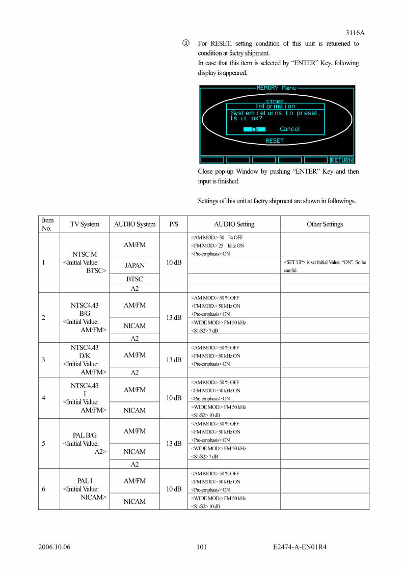
3116A
2006.10.06 E2474-A-EN01R4 101
③ For RESET, setting condition of this unit is returened to condition at factry shipment. In case that this item is selected by “ENTER” Key, following display is appeared. Close pop-up Window by pushing “ENTER” Key and then input is finished. Settings of this unit at factry shipment are shown in followings.
Item No. TV System AUDIO System P/S AUDIO Setting Other Settings
AM/FM <AM MOD.> 50 % OFF <FM MOD.> 25 kHz ON <Pre-emphasis> ON
JAPAN <SET UP> is set Initial Value: “ON”. So be careful.
BTSC
1 NTSC M
<Initial Value: BTSC>
A2
10 dB
AM/FM <AM MOD.> 50 % OFF <FM MOD.> 50 kHz ON <Pre-emphasis> ON
NICAM <WIDE MOD.> FM 50 kHz <S1/S2> 7 dB
2
NTSC4.43 B/G
<Initial Value: AM/FM>
A2
13 dB
AM/FM <AM MOD.> 50 % OFF <FM MOD.> 50 kHz ON <Pre-emphasis> ON
3
NTSC4.43 D/K
<Initial Value: AM/FM> A2
13 dB
AM/FM <AM MOD.> 50 % OFF <FM MOD.> 50 kHz ON <Pre-emphasis> ON
4
NTSC4.43 I
<Initial Value: AM/FM> NICAM
10 dB <WIDE MOD.> FM 50 kHz <S1/S2> 10 dB
AM/FM <AM MOD.> 50 % OFF <FM MOD.> 50 kHz ON <Pre-emphasis> ON
NICAM <WIDE MOD.> FM 50 kHz <S1/S2> 7 dB
5
PAL B/G <Initial Value:
A2>
A2
13 dB
AM/FM <AM MOD.> 50 % OFF <FM MOD.> 50 kHz ON <Pre-emphasis> ON
6 PAL I
<Initial Value: NICAM> NICAM
10 dB <WIDE MOD.> FM 50 kHz <S1/S2> 10 dB
I nf or mat i on
Ok Cancel
Syst em r et ur ns t o pr eset .I s i t ok?

3116A
2006.10.06 E2474-A-EN01R4 102
Item No. TV System AUDIO System P/S AUDIO Setting Other Settings
AM/FM <AM MOD.> 50 % OFF <FM MOD.> 50 kHz ON <Pre-emphasis> ON
7 PAL D
<Initial Value: AM/FM> A2
13 dB
AM/FM <AM MOD.> 50 % OFF <FM MOD.> 50 kHz ON <Pre-emphasis> ON
8 PAL N
<Initial Value: AM/FM> BTSC
10 dB
AM/FM <AM MOD.> 50 % OFF <FM MOD.> 50 kHz ON <Pre-emphasis> ON
9 PAL M
<Initial Value: BTSC> BTSC
10 dB
AM/FM <AM MOD.> 50 % OFF <FM MOD.> 50 kHz ON <Pre-emphasis> ON
NICAM <WIDE MOD.> FM 50 kHz <S1/S2> 12 dB
10
PAL D (CHINA)
<Initial Value: NICAM>
A2
10 dB
AM/FM <AM MOD.> 50 % OFF <FM MOD.> 50 kHz ON <Pre-emphasis> ON
11
PAL B (AUS)
<Initial Value: A2> A2
13 dB
AM/FM <AM MOD.> 50 % OFF <FM MOD.> 50 kHz ON <Pre-emphasis> ON
NICAM <WIDE MOD.> FM 50 kHz <S1/S2> 7 dB
12
SECAM B/G
<Initial Value: AM/FM>
A2
13 dB
AM/FM <AM MOD.> 50 % OFF <FM MOD.> 50 kHz ON <Pre-emphasis> ON
13
SECAM D/K/K1
<Initial Value: A2> A2
13 dB
AM/FM <AM MOD.> 50 % ON <FM MOD.> 50 kHz OFF <Pre-emphasis> OFF
14
SECAM L
<Initial Value: NICAM> NICAM
10 dB <WIDE MOD.> AM 50 % <S1/S2> 17 dB
Refer to <Initial Value> of item “7.4 Control Contents List” for other settings of this unit at factory shipment which are not written above.

3116A
2006.10.06 E2474-A-EN01R4 103
[F6 Key] (Indication: Digital) By pushing this Key, display is moved to “I/F Menu”. For change of setting, move following ① ~ ⑥ items by “UP / Down” Key, and input numerical value data directly. (In case of ② RS-232C Baud Rate, item selection is made.) After change of setting, input is finished by pushing “ENTER” Key. For returning to “Main Menu”, push [F6] Key (Indication: RETUERN).
<Example> In case that GP-IB address is set “5” 1. Push Key and move to “I/F Menu”. 2. Push “5” by “10” Keys. 3. Push “ENTER” Key and then, input is finished. 4. For returning to “Main Menu”, push [F6] Key (Indication: RETUERN).
① GP-IB Address Setting Range 0 ~ 30
② GP-IB Selecting Item “CR+LF/EOI”, “EOI”
③ RS-232C Baud Rate Selecting Item “9600”, “19200”, “38400”
④ LAN IP Address Setting Range (*24)
0.0.0.0 ~ 255.255.255.255 ⑤ LAN SUB NET MASK Setting Range (*24)
0.0.0.0 ~ 255.255.255.255 ⑥ LAN DEFAULT GATEWAY Setting Range (*24)
0.0.0.0 ~ 255.255.255.255 ⑦ LAN PORT Setting Range (*25)
0 ~ 65535
(*25) In case that LAN (OPTION) is not equipped, these are not indicated.
I/F Menu
RETURN
20GP-IB
CR+LF/EOIDelimiterRS-232C
19200
192.168.001.001
Address
Baud RateLAN
SUB NET MASKDEFAULT GATEWAYPORT
IP Address255.255.255.255255.255.255.25565535
① GP-IB Address
③ RS-232C Baud Rate
⑤ LAN SUB NET MASK
④ LAN IP Address
⑥ LAN DEFAULT GATEWAY
⑦ LAN PORT
② GP-IB Delimiter
I/F Menu
RETURN
20GP-IB
CR+LF/EOIDelimiterRS-232C
19200
192.168.001.001
Address
Baud RateLAN
SUB NET MASKDEFAULT GATEWAYPORT
IP Address255.255.255.255255.255.255.25565535

3116A
2006.10.06 E2474-A-EN01R4 104
7. Remote Control This unit equips interfaces of “GP-IB” and “RS-232C” at standard (“LAN” is option), operation in menu indication of this unit can be controlled remotely by communication of each interface. In this time, following indication is displayed at vacuum fluorescence display and Keys other than “LOCAL” Key are not accepted.
7.1 LAN Interface (OPTION) 7.1.1 Communication and Operating Mode
This unit supports “TCP/IP” as communication system and moreover, communication is made by using Eiden’s unique protocol shown in “7.1.4 Communication Format”. Programming interface supports “SOCKET”, so that “SOCKET” can be used for making client application. Also, this unit and control device (PC) work on server mode, which PC as a client connects firstly with this unit as a server. For Command and command reception, “CR” (0x0D) is added for delimiter.
7.1.2 Pin Assignment of LAN (10Base-T) Interface
List 7.1.2 Pin Assignment of ETHERNET Connector Pin No. Abbreviation Direction Name
1 TXD+ Device → PC Transmitting data (+) 2 TXD- → Transmitting data (-) 3 RXD+ ← Receiving data (+) 4 - - Not used 5 - - Not used 6 RXD+ ← Receiving data (-) 7 - - Not used 8 - - Not used
Use cross cable for connection with PC.
Fig. 7.1.2 Pin Assignment of ETHERNET Connector
8 1
* REMOTE( RS- 232C) * KEY oper at i on i s i nval i d
/ 75Hz

3116A
2006.10.06 E2474-A-EN01R4 105
7.1.3 Communication Procedure Remote action is occurred from host PC side always.
① Command Reception RVOPE=001 (Busy Response) is set. ② Command Analyze Response corresponded to command is set. ③ Response is transmitted In case of each abnormal condition and normal condition, this response is kept until next command reception is started. 7.1.4 Communication Format ① Control Information Transmission
(Command) Header + = + Blank + Data + Delimiter (“CR”) In case that data more than 1 are wanted to be transmitted in 1 time, it is possible to divide by “,” (Comma). (Command) Header + = + Blank + Data + , + Header + = + Blank + Data + , + ... + Delimiter (“CR”) Blank is possible to be omitted and character is all “Capital Letter” and max. upto 255 characters. (Response) RVOPE=XXX + Delimiter (“CR”) (Refer to “7.4.3 Contents List of Response Reply”)
<Example> “RF output frequency 900.00 MHz” is transmitted. (Command) STATE? + Delimiter
(Response) RVOPE=XXX + Delimiter (“CR”) (Refer to “7.4.3 Contents List of Response Reply”)
Command Transmission
Response Reply
3116A Host PC

3116A
2006.10.06 E2474-A-EN01R4 106
② Setting Information Request and Device Information Request (Command) Command + ? + Delimiter (“CR”) (Response) (At normal condition) Command + = + Replied Data + Delimiter (“CR”) (At abnormal condition) RVOPE=XXX + Delimiter (“CR”) (Refer to “7.3.2 Contents List of Response Reply”)
<Example> Example of Device Setting Information Request (Command) STATE? + Delimiter (“CR”)
(Response Example) (At normal condition) STATE=0000000 + Delimiter (“CR”) (At abnormal condition) RVOPE=XXX + Delimiter (“CR”) (Refer to “7.4.3 Contents List of Response Reply”)

3116A
2006.10.06 E2474-A-EN01R4 107
7.2 GP-IB Interface 7.2.1 Communication System
Communication is made in conforming to IEEE-488. (Conforming to IEEE 488.2) 7.2.2 Transmitting / Receiving Data
7 bits ASCII is used for Transmitting / Receiving Data. Delimiter is selected “EOI” or “CR (Carriage Return character) + LF (Line Feed character) + EOI” and used.
7.2.3 GP-IB (IEEE-488.2) Interface Pin Assignment
List 7.2.3 GP-IB Interface Pin Assignment Pin No. Abbreviation Name 1 DIO1 2 DIO2 3 DIO3 4 DIO4
Data Input Output
5 EOI End or Identify 6 DAV Data Valid 7 NRFD Not Ready for Data 8 NDAC Not Data Accepted 9 IFC Interface Clear 10 SRQ Service Request 11 ATN Attention 12 GND GND 13 DIO5 14 DIO6 15 DIO7 16 DIO8
Data Input Output
17 REN Remote Enable 18 GND
~ ~
24 GND
GND
Fig. 7.2.3 GP-IB Connector Pin Assignment
112
24 13

3116A
2006.10.06 E2474-A-EN01R4 108
7.2.4 Service Request and Status / Event Command ① Service Request
GP-IB is conforming to IEEE-488.2. For conforming to standard, following status configuration and 488.2 common commands are supported.
Fig. 7.2.4 Status Byte Register Configuration
Configuration of summary massage for service request of status byte register is shown in followings.

3116A
2006.10.06 E2474-A-EN01R4 109
Table 7.2.4-1 IEEE-488.2 Supporting Command (Essential command is supported.) Item No. Command Contents / Data
1 *CLS SBR and SESR are cleared and output buffer relating to status is cleared. <Replaying Data> None
2 *ESE SESER is set. Each bit of SESR is set enable / disable. <Replaying Data> 0 ~ 255 (Example) “*ESE 128” “*ESE 15”
3 *ESE? Command for request of setting value of SESER <Replaying Data> 0 ~ 255
4 *ESR? Command for request of present value of SESR <Replaying Data> 0 ~ 255 (Example) “+128” “+15” After replying, SESR is cleared.
5 *IDN? Command for request of ID <Replaying Data> 4 fields divided by comma are replied. [Field 1], [Field 2], [Field 3], [Field 4] [Field 1] = EIDEN (Manufacturer’s Name) [Field 2] = 3116A (Model Name) [Field 3] = 0 (Serial No. (0 fixed)) [Field 4] = Version No. indicated on LCD on front panel (Example)“EIDEN,3116A,0,25.5”
6 *OPC This command dose not operate and process anything. <Replaying Data> None
7 *OPC? <Replaying Data> 1 (1: Fixed) (Example) “+1” 8 *RST This command dose not operate and process anything.
<Replaying Data> None 9 *SRE SRER is set.
Each bit of SESR is set enable / disable. As control of SRQ bit is possible, SRQ ON / OFF setting is possible. <Data> 0 ~ 255 (Example) “*SRE 128” “*SRE 15”
10 *SRE? Command for request of setting value of SRER <Replaying Data> 0 ~ 255 (Example) “*+ 128” “*+ 15”
11 *STB? Command for request of present value of SBR <Replaying Data> 0 ~ 255 (Example) “*+ 128” “*+ 15”
12 *TST? This command dose not operate and process anything. <Replaying Data> - (-: Fixed)
13 *WAI This command dose not operate and process anything. <Replaying Data> None

3116A
2006.10.06 E2474-A-EN01R4 110
② Details of Register 1. SBR: Status Byte Register Byte data taken at serial pole - Relative command “*STB?” 2. SRER: Service Request Enable Register Register for setting valid / invalid of which summary massage in SBR against service request. - Relative command “*SRE ”, “*SRE?” 3. SESR: Standard Event Status Register Register for definition of standard event - Relative command “*ESR?” 4. SESER: Standard Event Status Enable Register Register for setting valid / invalid of which summary massage in SESR against ESB bit of SBR. - Relative command “*ESE ”, “ESE?”

3116A
2006.10.06 E2474-A-EN01R4 111
1. SBR: Status Byte Register Table ②-1 Status Byte Register
Bit Name Contents SRER Initial Value 0 SB0 Set (1) in case that alarm factor is occurring. (0) 1 SB1 No definition Reset always (0) (0) 2 SB2 No definition Reset always (0) (0) 3 SB3 No definition Reset always (0) (0) 4 MAV Message Available Summary Bit
This is not used. [Always set (0)] (0)
5 ESB Event Summary Bit Set (1) in case that bit factor of SER on corresponded bit which is set enable by SESER is occurred.
(0)
6 RQS (MSS) RQS Bit (Master Summary Status) Set (1) in case that bit factor of SBR on corresponded bit which is set enable by SRES is occurred.
X
7 EMS Not used in this unit. Always (0) (0)
This register value set at SRQ occurrence is made polling or SRQ time out (Reset at 1 sec. 00h), but past occurrence factor is kept for asking of [*STB?] until next SRQ occurrence. MSS bit is set by re-inspecting factor bit at each time.

3116A
2006.10.06 E2474-A-EN01R4 112
2.SESR: Standard Event Status Register Table ②-3 Status Byte Register
Bit Name Contents SESER Initial Value0 OPC Operation Complete
Set (1) during pending or in case that acceptance of new command is ready, after finished executing process.
(0)
1 RQC Bus control request (Request Control) Not used in this unit. [Reset always (0)]
(0)
2 QYE Query error (Query Error) This unit prepares reply telegram always. [Reset always (0)]
(0)
3 DDE Device-dependent Error Set (1) when error other than QYE, EXE and CME is occurred. No definition in this unit [Reset always (0)]
(0)
4 EXE Execution Error Set (1) in case that command which can not be executed is received. (At parameter error in case that data are not in range and etc.)
(0)
5 CME Command Error Set (1) at command error
(0)
6 URQ User Request Not used in this unit. [Reset always (0)]
(0)
7 PON Power turned ON (Power On) Set (1) at power turned ON
(0)
This register value is not reset (00h) by POLL, SRQ time out. So, reading of contents by [*ESR?] is possible after time passing. But, at occurrence of next SRQ, factor bit is processed by checking (SESR) in re-set (00h) condition. This register value is re-set (00h) when [*CLS] command and [*ESR?] command are processed.

3116A
2006.10.06 E2474-A-EN01R4 113
7.2.5 Communication Format ① Control Information Transmission
(Command) Header + = + Blank + Data + Delimiter In case that data more than 1 are wanted to be transmitted in 1 time, it is possible to divide by “,” (Comma). (Command) Header + = + Blank + Data + , + Header + = + Blank + Data + , + ... + Delimiter Blank is possible to be omitted and character is all “Capital Letter” and max. upto 255 characters.
<Example> “RF output frequency 900.00 MHz” is transmitted. (Command) SYSFR=900.00 + Delimiter ② Setting Information Request and Device Information Request
(Command) Header + ? + Delimiter (Response) Header + = + Replied Data + Delimiter In case that transmission request (MTA) is transmitted after “Setting Information and Equipment Information Request” is transmitted to this unit, replay is transmitted by above format.
<Example> Setting value information of this unit is requested. (Command) STATE? + Delimiter
(Response Example) STATE=0000000 + Delimiter

3116A
2006.10.06 E2474-A-EN01R4 114
7.3 RS-232C Interface 7.3.1 Interface Specification
Table 7.3.1 Item No. Item Specifications
1 Electrical Specifications RS-232C 2 Communication System All dual asynchronous system 3 Baud Rate Selection from 9600 bps, 19200 bps or 38400 bps 4 Data Bit 8 bits 5 Parity No 6 Stop Bit 1 bit 7 Communication Control No
7.3.2 Pin Assignment of RS-232C Interface
Table 7.3.2 RS-232C Connector Pin Assignment Pin No. Abbreviation Direction Name
1 NC Not connected 2 TxD This unit → PC Transmitting data 3 RxD ← Receiving data 4 DR Data set ready
(Through Pin6: ER) 5 SG Signal ground 6 ER Data terminal ready
(Through Pin4: DR) 7 CS Enable transmission
(Through Pin8: RS) 8 RS Transmission request
(Through Pin7: CS) 9 NC Not connected
Use straight cable for connection with PC.
Fig. 7.3.2 RS-232C Connector Pin Assignment
15
9 6

3116A
2006.10.06 E2474-A-EN01R4 115
7.3.3 Communication Procedure Remote action is occurred from host PC side always.
① Command Reception RVOPE=001 (Busy Response) is set. ② Command Analyze Response corresponded to command is set. ③ Response is transmitted In case of each abnormal condition and normal condition, this response is kept until next command reception is started. 7.3.4 Communication Format ① Control Information Transmission
(Command) Header + = + Blank + Data + Delimiter (“CR”) In case that data more than 1 are wanted to be transmitted in 1 time, it is possible to divide by “,” (Comma). (Command) Header + = + Blank + Data + , + Header + = + Blank + Data + , + ... + Delimiter (“CR”) Blank is possible to be omitted and character is all “Capital Letter” and max. upto 255 characters. (Response) RVOPE=XXX + Delimiter (“CR”) (Refer to “7.4.3 Contents List of Response Reply”)
<Example> “RF output frequency 900.00 MHz” is transmitted. (Command) SYSFR=900.00 + Delimiter (“CR”)
(Response) RVOPE=XXX + Delimiter (“CR”) Refer to “7.4.3 Contents List of Response Reply”)
Command Transmission
Response Reply
3116A Host PC

3116A
2006.10.06 E2474-A-EN01R4 116
② Setting Information Request and Device Information Request (Command) Command + ? + Delimiter (“CR”) (Response) (At normal condition) Command + = + Replied Data + Delimiter (“CR”) (At abnormal condition) RVOPE=XXX + Delimiter (“CR”) (Refer to “7.3.3 Contents List of Response Reply”)
<Example> “RF output frequency 900.00 MHz” is transmitted. (Command) STATE? + Delimiter (“CR”)
(Response Example) (At normal condition) STATE=0000000 + Delimiter (“CR”) (At abnormal condition) RVOPE=XXX + Delimiter (“CR”) (Refer to “7.4.3 Contents List of Response Reply”)

3116A
2006.10.06 E2474-A-EN01R4 117
7.4 Control Contents List List 7.4-1
Command Item No. Header
Setting Request
‘?’
Control ‘=’
Data (Character) Contents
“SYSTEM” 0 <TV Standard> :NTSC M 1 :NTSC4.43 B/G 2 :NTSC4.43 D/K 3 :NTSC4.43 I 4 :PAL B/G 5 :PAL I 6 :PAL D 7 :PAL-N 8 :PAL-M 9 :PAL D(CHINA) 10 :PAL B(AUS) 11 :SECAM B/G 12 :SECAM D/K/K1
1 SYSTV
13 :SECAM L
2 SYSFR Numerical Value(6 Characters)
***.**
<Frequency> <Initial Value: 900.00> 030.00 [MHz] ~ 900.00 [MHz]
3 SYSLV Numerical Value(5 Characters)
***.*
<Level> < Initial Value: -10.0> -80.0 [dBm] ~ 000.0 [dBm] <At P/S Reverse> -96.0 [dBm] ~ -16.0 [dBm]
0 <RFv> :OFF 4 SYSRV 1 :ON <Initial Setting> 0 <RFa> :OFF 5 SYSRA 1 :ON <Initial Setting> 0 <P/S> :Normal <Initial Setting> 6 SYSPR 1 :Reverse
7 SYSPS Numerical Value(5 Characters)
*****
<P/S> -30.0 [dB] ~ -06.0 [dB] -30.0 [dB] ~ -10.0 [dB](AM modulation) <At P/S Reverse> -14.0 [dB] ~ +10.0 [dB] -14.0 [dB] ~ +06.0 [dB](At AM modulation)
0 <Sideband> :Lower 8 SYSSD 1 :Upper <Initial Setting>

3116A
2006.10.06 E2474-A-EN01R4 118
Command
Item No. Header
Setting Request
‘?’
Control ‘=’
Data (Character) Contents
“VIDEO” 0 <Video Source> :EXT 9 VDOVS 1 :INT <Initial Setting>
10 VDOVM Numerical Value(5 Characters)
***.*
<Video Modulation> <Initial Value: 87.5> 000.0 [%] ~ 105.0 [%] (SECAM-L) 000.0 [%] ~ 120.0 [%] (Other than SECAM-L)
0 <Video Modulation> :OFF 11 VDOMF 1 :ON <Initial Setting> 0 <Aspect Ratio> :4:3 <Initial Setting>
12 VDOAR 1 :16:9 Valid after “Cross Hatch”, “Circlecross” or “Afterimage” is selected.
0000 Color Bar Full Field1 <Initial Setting> 0001 Full Field2 0002 Split Field 0003 SMPTE 0100 Cross Hatch Cross (posi) 0101 Dot (posi) 0102 CrossDot (posi) 0103 TopLeft (posi) 0104 Cross (nega) 0105 Dot (nega) 0106 CrossDot (nega) 0107 TopLeft (nega) 0200 Circlecross C.Cross (posi) 0201 C.Cross (nega) 0300 Multi Burst M.B. Type1 (100 %) 0301 M.B. Type2 (75 %) 0302 M.B. Type3 (30 %) 0400 Mod StairStep Mod 10step 0500 White White 100 0501 White 75 0502 White 50 0503 White 25 0504 Raster 0600 Black & White W/B 2 division 0601 B/W 2 division 0602 W/B 4 division
13 VDOVP
0700 Mod Ramp Mod Ramp

3116A
2006.10.06 E2474-A-EN01R4 119
Command
Item No. Header
Setting Request
‘?’
Control ‘=’
Data (Character) Contents
“VIDEO” 0800 Purity: Red 0801 Green 0802 Blue 0900 Afterimage Red+MoveWin(W) 0901 Red+MoveWin(G) 0902 Red+MoveWin(B) 0903 Green+MoveWin(W) 0904 Green+MoveWin(R) 0905 Green+MoveWin(B) 0906 Biue+MoveWin(W) 0907 Biue+MoveWin(R) 0908 Biue+MoveWin(G) 0909 White+MoveWin(R) 0910 White+MoveWin(G) 0911 White+MoveWin(B) 1000 Monoscope (Lion)
1100 Color Pattern (Invalid when PAL-M, PAL-N or NTSC4.43 is selected.)
1200 DEM
1300 OPTION 1 (Refer to other part for OPTION.)
1301 OPTION 2 1302 OPTION 3 1303 OPTION 4 1304 OPTION 5 1305 OPTION 6 1306 OPTION 7
13 VDOVP
1307 OPTION 8 <Interval Time> 0 1 [Sec.] 1 2 [Sec.] <Initial Value: 1> 2 3 [Sec.] 3 4 [Sec.]
14 INTVL
4 5 [Sec.]
(Valid when Afterimage is selected.)
0 <VBL> :20H <Initial Setting> 15 VDOVL
1 :21H
(Valid when NTSC M is selected.)

3116A
2006.10.06 E2474-A-EN01R4 120
Command
Item No. Header
Setting Request
‘?’
Control ‘=’
Data (Character) Contents
“Video Output”
16 VOLLU Numerical Value(3 Characters)
***
<Luminance Level> <Initial Value: 100> 000[%] ~ 110[%]
17 VOLCH Numerical Value(3 Characters)
***
<Chrominance Level> <Initial Value: 100> 000[%] ~ 110[%]
18 VOLSY Numerical Value(3 Characters)
***
<Sync Level> <Initial Value:100> 000[%] ~ 110[%]
19 VOLRG Numerical Value(3 Characters)
***
<RGB Level> <Initial Value:100> 000[%] ~ 110[%]
20 VOLYL Numerical Value(3 Characters)
***
<Y Level> <Initial Value:100> 000[%] ~ 110[%]
21 VOLPB Numerical Value(3 Characters)
***
<Pb Level> <Initial Value:100> 000[%] ~ 110[%]
22 VOLPR Numerical Value(3 Characters)
***
<Pr Level> <Initial Value:100> 000[%] ~ 110[%]
These are not reflected to RF output.
0 <Luminance> :OFF 23 VOOLU 1 :ON <Initial Setting> 0 <Chrominance> :OFF 24 VOOCH 1 :ON <Initial Setting> 0 <Sync.> :OFF
25 VOOSY 1 :ON <Initial Setting>
0 <SETUP>:OFF 26 VOOSU 1 :ON
<Initial Setting>
(Valid when NTSC M is selected.)
0 <BURST> :OFF 27 VOOBU 1 :ON <Initial Setting> 0 <IDENT> :OFF
28 VOOID 1 :ON <Initial Setting>
(Valid when SECAM L is selected.)
0 <VITS> :OFF <Initial Setting> 29 VOOVI 1 :ON 0 <R> :OFF 30 VOORF 1 :ON <Initial Setting> 0 <R Sync> :OFF 31 VOORS 1 :ON <Initial Setting> 0 <G> :OFF 32 VOOGF 1 :ON <Initial Setting> 0 <G Sync> :OFF 33 VOOGS 1 :ON <Initial Setting>

3116A
2006.10.06 E2474-A-EN01R4 121
Command
Item No. Header
Setting Request
‘?’
Control ‘=’
Data (Character) Contents
“Video Output” 0 <B> :OFF 34 VOOBF 1 :ON <Initial Setting> 0 <B Sync> :OFF 35 VOOBS 1 :ON <Initial Setting> 0 <EURO Output> :Y/C <Initial Setting> 1 :RGB 2 :CVBS 36 VOEOS
3 :CVBS_RGB 0 <EURO CVBS Status> :OFF
37 VOECS 1 :ON <Initial Setting>
0 <Video Format> :VGA(640x480)31.5kHz/60Hz <Initial Setting>
1 :SVGA(800x600) 37.9kHz/60Hz 2 :XGA(1024x768) 48.4kHz/60Hz 3 :XGA(1024x768) 56.5kHz/70Hz 4 :XGA(1024x768) 60.0kHz/75Hz 5 :SXGA(1280x1024) 64.0kHz/60Hz
38 VODIG
6 :SXGA(1280x1024) 80.0kHz/75Hz 0 <On Screen Display> :OFF<Initial Setting> 1 :Top Left 2 :Top Right 3 :Bottom Left 4 :Bottom Right
39 VODSD
5 :Center

3116A
2006.10.06 E2474-A-EN01R4 122
Command
Item No. Header
Setting Request
‘?’
Control ‘=’
Data (Character) Contents
“Audio” 0 <Audio System> :AM/FM 1 :NICAM 2 :A2 3 :JAPAN
40 AUDIO
4 :BTSC “WIDE”
41 AWACW Numerical Value(6 Characters)
***.**
<CW frequency (AM)> <Initial Value: 003.00> 000.01 [kHz] ~ 150.00 [kHz]
42 AWFCW Numerical Value(6 Characters)
***.**
<CW frequency (FM)> <Initial Value: 003.00> 000.01 [kHz] ~ 150.00 [kHz] (When Pre-Em is set to ON, the performance to “15 kHz” is guaranteed.)
43 AWDSS Numerical Value(6 Characters)
***.**
<SWEEP start frequency> <Initial Value: 000.01> 000.01 [kHz] ~ 140.00 [kHz]
44 AWDSE Numerical Value(6 Characters)
***.**
<SWEEP stop frequency> <Initial Value: 100.00> 001.00 [kHz] ~ 150.00 [kHz] (When the starting frequency is set to 0.01 kHz, the stopping frequency can be set to less than 100 kHz.)
45 AWDST Numerical Value(2 Characters)
**
<SWEEP time> <Initial Value: 10> 01 [s] ~ 10 [s]
“AM/FM” (Valid when “Audio System: AM/FM” is selected) 0 <WIDE Input> :EXT 1 :INT (CW) <Initial Setting> 46 AAFWI 2 :INT (SWEEP)
(Only FM modulation)0 <AM Modulation> :OFF 47 AAFAF 1 :ON
48 AAFAM Numerical Value(4 Characters)
**.*
<AM Modulation> 00.0[%] ~ 95.0[%]
0 <FM Modulation> :OFF 49 AAFFF 1 :ON
50 AAFFM Numerical Value(4 Characters)
**.*
<FM Modulation> 00.0[kHz] ~ 99.0[kHz]
0 <Pre-emphasis> :OFF 51 AAFPE 1 :ON

3116A
2006.10.06 E2474-A-EN01R4 123
Command
Item No. Header
Setting Request
‘?’
Control ‘=’
Data (Character) Contents
“NICAM” (Valid when “Audio System: NICAM” is selected.) 0 <Mode> :STEREO <Initial Setting> 1 :MONO1/MONO2 2 :MONO1/DATA
52
ANCMD
3 :DATA 0 <WIDE Input> :EXT 1 :INT (CW) <Initial Setting>
53
ANCWI
2 :INT (SWEEP) (Valid when TV System: Other than L system is selected.)
0 <WIDE Modulation> :OFF 54 ANCWF 1 :ON <Initial Setting>
55
ANCWM
Numerical Value(3 Characters)
***
<WIDE Modulation> 00.0 [%] ~ 95.0 [%] (Valid when TV System: L system” is selected.) 00.0 [kHz] ~ 99.0 [kHz] (Valid when TV System: Other than L system is selected.)
0 <L/M1 Source> :EXT 1 :100 Hz 2 :400 Hz 3 :1 kHz <Initial Setting> 4 :3 kHz 5 :7.5 kHz 6 :10 kHz
56
ANCLS (*26)
7 :15 kHz 0 <L/M1 Modulation> :OFF 57 ANCLF
(*26)
1 :ON <Initial Setting> 58 ANCLM
(*26)
Numerical Value(3 Characters)
***
<L/M1 Modulation> <Initial Value: 100> 000 [%] ~ 100 [%]
0 <R/M2 Source> :EXT 1 :100 Hz 2 :400 Hz 3 :1 kHz <Initial Setting> 4 :3 kHz 5 :7.5 kHz 6 :10 kHz
59
ANCRS (*26)(*27)
7 :15 kHz 0 <R/M2 Modulation> :OFF 60 ANCRF
(*26)(*27)
1 :ON <Initial Setting> 61 ANCRM
(*26)(*27)
Numerical Value(3 Characters)
***
<R/M2 Modulation> <Initial Value: 100> 000 [%] ~ 100 [%]
(*26) Invalid when “Transmitting Mode: DATA” is selected. (*27) Invalid when “Transmitting Mode: MONO1 / DATA” is selected.

3116A
2006.10.06 E2474-A-EN01R4 124
Command
Item No. Header
Setting Request
‘?’
Control ‘=’
Data (Character) Contents
“NICAM” (Valid when “Audio System: NICAM” is selected.) 0 <Silence Code Level> :OFF <Initial Setting> 1 :-72 dB 2 :-66 dB 3 :-60 dB 4 :-54 dB 5 :-48 dB 6 :-42 dB
62 ANCSL (*28)
7 :-36 dB
0 <Silence Code Timing> :8 ms <Initial Setting>
1 :9 ms 2 :10 ms 3 :11 ms
63 ANCST (*28)
4 :12 ms 0 <CIB Data Frame> :Async<Initial Setting> 64 ANCCF
(*28) 1 :sync 0 <CIB EXE> :OFF <Initial Setting> 65 ANCCE
(*28) 1 :ON 0 <CIB Data> :00 <Initial Setting> 1 :01 2 :10 66 ANCCD
(*28)
3 :11
67 ANCAD
Hexadecimal numerical value(3 Characters)
***
<Add Data> <Initial Value:000> [0x]000 ~ [0x]7FF
0 <Bit4 Control> :OFF <Initial Setting> 68 ANCBC 1 :ON
69 ANCDD (*29)
Hexadecimal numerical value(4 Characters)
****
<Digital Data> <Initial Value:0000> [0x]0000 ~ [0x]FFFF
70 ANCSA Numerical value(3 Characters)
***
<S1/S2> -30 [dB] ~ 000 [dB]
0 <S2> :OFF 71 ANCSF 1 :ON <Initial Setting>
0 <Pre-emphasis> :OFF 72 ANCPE 1 :ON <Initial Setting> (*28) Only “Video System: B/G”. (*29) Invalid when “Transmitting Mode: STEREO” or “Transmitting Mode: MONO1 / MONO2” is selected.

3116A
2006.10.06 E2474-A-EN01R4 125
Command
Item No. Header
Setting Request
‘?’
Control ‘=’
Data (Character) Contents
“A2” (Valid when “Audio System: A2” is selected.) 0 <Mode> :MONO 1 :TWO SOUND 73 A2CMD 2 :STEREO <Initial Setting> 0 <L/M1 Source> :EXT 1 :100 Hz 2 :400 Hz 3 :1 kHz <Initial Setting> 4 :3 kHz 5 :7.5 kHz 6 :10 kHz
74 A2CLS
7 :13 kHz 0 <L/M1 Modulation> :OFF 75 A2CLF 1 :ON <Initial Setting>
76 A2CLM Numerical value(3 Characters)
***
<L/M1 Modulation> <Initial Value: 100> 000 [%] ~ 199 [%]
0 <R/M2 Source> :EXT 1 :100 Hz 2 :400 Hz 3 :1 kHz <Initial Setting> 4 :3 kHz 5 :7.5 kHz 6 :10 kHz
77 A2CRS (*30)
7 :13 kHz 0 <R/M2 Modulation> :OFF 78 A2CRF
(*30) 1 :ON <Initial Setting>
79 A2CRM (*30)
Numerical value(3 Characters)
***
<R/M2 Modulation> <Initial Value:100> 000[%] ~ 199[%]
0 <PILOT Level> :OFF 80 A2CPF 1 :ON <Initial Setting>
81 A2CPL Numerical value(3 Characters)
***
<PILOT Level> <Initial Value:100> 000[%] ~ 199[%]
0 <IDENT Modulation> :OFF 82 A2CIF (*30) 1 :ON <Initial Setting>
83 A2CIM (*30)
Numerical value(3 Characters)
***
<IDENT Modulation><Initial Value:50> 000 [%] ~ 100 [%]
(*30) Invalid when “Transmitting Mode: MONO” is selected.

3116A
2006.10.06 E2474-A-EN01R4 126
Command
Item No. Header
Setting Request
‘?’
Control ‘=’
Data (Character) Contents
“A2” (Valid when “Audio System: A2” is selected.)
84 A2CSA Numerical value(3 Characters)
***
<S1/S2> <Initial Value: -07> -30 [dB] ~ 000 [dB]
0 <S2> :OFF 85 A2CSF 1 :ON <Initial Setting> 0 <Pre-emphasis> :OFF 86 A2CPE 1 :ON <Initial Setting>

3116A
2006.10.06 E2474-A-EN01R4 127
Command
Item No. Header
Setting Request
‘?’
Control ‘=’
Data (Character) Contents
“JAPAN” (Valid when “Audio System: JAPAN” is selected.) 0 <Mode> :MONO 1 :MULTI 87 AJPMD 2 :STEREO <Initial Setting> 0 <L/MAIN Source> :EXT 1 :100 Hz 2 :400 Hz 3 :1 kHz <Initial Setting> 4 :3 kHz 5 :7.5 kHz 6 :10 kHz
88 AJPLS
7 :12.5 kHz 0 <L/MAIN Modulation> :OFF 89 AJPLF 1 :ON<Initial Setting>
90 AJPLM Numerical value(3 Characters)
***
<L/MAIN Modulation> <Initial Value: 100> 000 [%] ~ 199 [%]
0 <R/SUB Source> :EXT 1 :100 Hz 2 :400 Hz 3 :1 kHz <Initial Setting> 4 :3 kHz 5 :7.5 kHz 6 :10 kHz
91 AJPRS (*31)
7 :12.5 kHz 0 <R/SUB Modulation> :OFF 92 AJPRF
(*31) 1 :ON <Initial Setting>
93 AJPRM (*31)
Numerical value(3 Characters)
***
<R/SUB Modulation> <Initial Value: 100> 000 [%] ~ 199 [%]
0 <R/SUB Level> :OFF 94 AJPRO (*31) 1 :ON <Initial Setting>
95 AJPRL (*31)
Numerical value(3 Characters)
***
<R/SUB Level> <Initial Value:080> 000[%] ~ 199[%]

3116A
2006.10.06 E2474-A-EN01R4 128
Command
Item No. Header
Setting Request
‘?’
Control ‘=’
Data (Character) Contents
“JAPAN” (Valid when “Audio System: JAPAN” is selected.) 0 <Q Modulation> :OFF 96 AJPQF
(*31) 1 :ON <Initial Setting>
97 AJPQM (*31)
Numerical value(3 Characters)
***
<Q Modulation> <Initial Value:60> 000[%] ~ 100[%]
0 <Q Level> :OFF 98 AJPQO (*31) 1 :ON <Initial Setting>
99 AJPQL (*31)
Numerical value(3 Characters)
***
<Q Level> <Initial Value:100> 000[%] ~ 199[%]
0 <Pre-emphasis> :OFF 100 AJPPE 1 :ON <Initial Setting> (*31) Invalid when “Transmitting Mode: MONO” is selected.

3116A
2006.10.06 E2474-A-EN01R4 129
Command
Item No. Header
Setting Request
‘?’
Control ‘=’
Data (Character) Contents
“BTSC” (Valid when “Audio System: BTSC” is selected.) 0 <Mode> :MONO 101 ABTMD 1 :STEREO <Initial Setting> 0 <L Source> :100 Hz 1 :300 Hz <Initial Setting> 2 :1 kHz 3 :2 kHz 4 :3 kHz 5 :7 kHz 6 :8 kHz
102 ABTLS
7 :10 kHz 0 <R Source> :100 Hz 1 :300 Hz 2 :1 kHz 3 :2 kHz 4 :3 kHz <Initial Setting> 5 :7 kHz 6 :8 kHz
103 ABTRS
7 :10 kHz 0 <L Modulation> :OFF 104 ABTLF 1 :ON <Initial Setting> 0 <R Modulation> :OFF 105 ABTRF 1 :ON <Initial Setting>
106 ABTLM Numerical value(3 Characters)
***
<L Modulation> <Initial Value: 020> 000 [%] ~ 199 [%]
107 ABTRM Numerical value(3 Characters)
***
<R Modulation> <Initial Value: 020> 000 [%] ~ 199 [%]
0 <SAP Source> :100Hz 1 :300 Hz 2 :1 kHz <Initial Setting> 3 :2 kHz 4 :3 kHz 5 :7 kHz 6 :8 kHz
108 ABTSS
7 :10 kHz 0 <SAP Modulation> :OFF 109 ABTSF 1 :ON <Initial Setting>
110 ABTSM Numerical value(3 Characters)
***
<SAP Modulation> <Initial Value:100> 000 [%] ~ 199 [%]
0 <SAP Level> :OFF 111 ABTSO 1 :ON <Initial Setting>

3116A
2006.10.06 E2474-A-EN01R4 130
Command
Item No. Header
Setting Request
‘?’
Control ‘=’
Data (Character) Contents
112 ABTSL Numerical value(3 Characters)
***
<SAP Level> <Initial Value:100> 000 [%] ~ 199 [%]
0 <PILOT Level> :OFF 113 ABTPO (*32) 1 :ON <Initial Setting>
114 ABTPL (*32)
Numerical value(3 Characters)
***
<PILOT Level> <Initial Value:100> 000 [%] ~ 199 [%]
115 ABTPP (*32)
Numerical value(2 Characters)
**
<Sync-PILOT Phase> <Initial Value:00> 00 ~15 (360° are divided into 16.)
0 <Pre-emphasis/NR> :OFF 116 ABTPE 1 :ON <Initial Setting> (*32) Invalid when “Transmitting Mode: MONO” is selected.
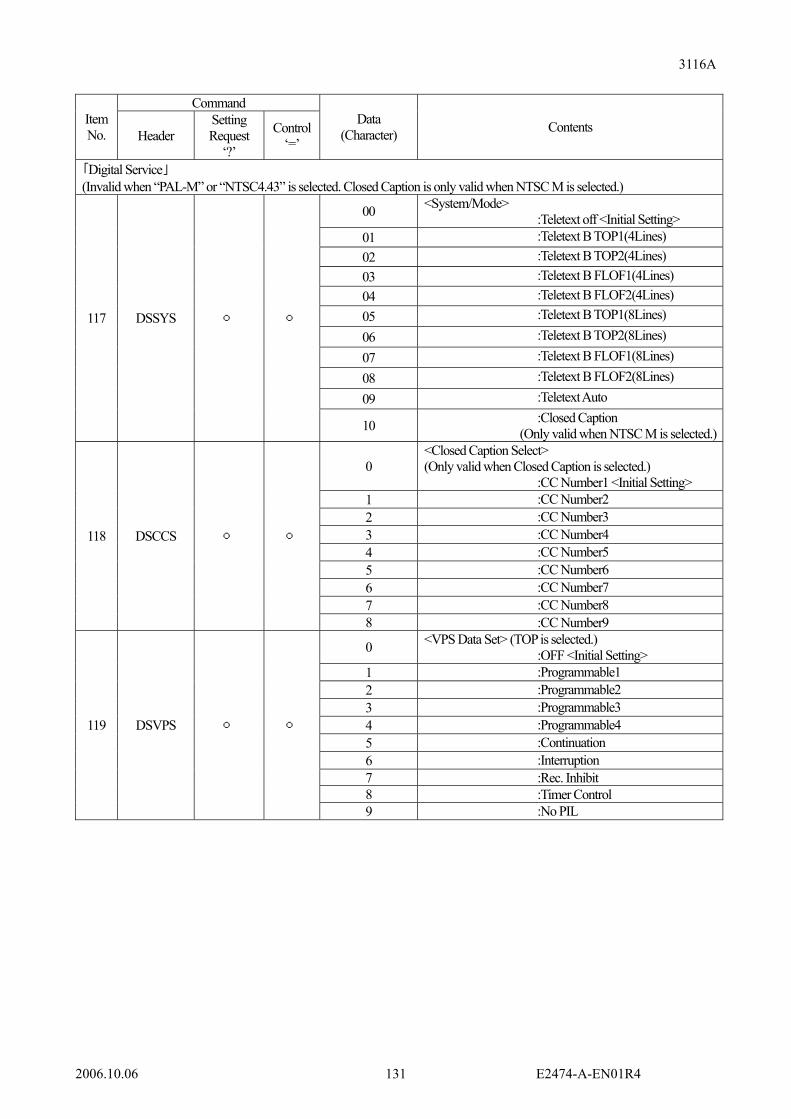
3116A
2006.10.06 E2474-A-EN01R4 131
Command
Item No. Header
Setting Request
‘?’
Control ‘=’
Data (Character) Contents
「Digital Service」 (Invalid when “PAL-M” or “NTSC4.43” is selected. Closed Caption is only valid when NTSC M is selected.)
00 <System/Mode> :Teletext off <Initial Setting>
01 :Teletext B TOP1(4Lines) 02 :Teletext B TOP2(4Lines) 03 :Teletext B FLOF1(4Lines) 04 :Teletext B FLOF2(4Lines) 05 :Teletext B TOP1(8Lines) 06 :Teletext B TOP2(8Lines) 07 :Teletext B FLOF1(8Lines) 08 :Teletext B FLOF2(8Lines) 09 :Teletext Auto
117 DSSYS
10 :Closed Caption (Only valid when NTSC M is selected.)
0 <Closed Caption Select> (Only valid when Closed Caption is selected.) :CC Number1 <Initial Setting>
1 :CC Number2 2 :CC Number3 3 :CC Number4 4 :CC Number5 5 :CC Number6 6 :CC Number7 7 :CC Number8
118 DSCCS
8 :CC Number9
0 <VPS Data Set> (TOP is selected.) :OFF <Initial Setting>
1 :Programmable1 2 :Programmable2 3 :Programmable3 4 :Programmable4 5 :Continuation 6 :Interruption 7 :Rec. Inhibit 8 :Timer Control
119 DSVPS
9 :No PIL

3116A
2006.10.06 E2474-A-EN01R4 132
Command
Item No. Header
Setting Request
‘?’
Control ‘=’
Data (Character) Contents
「Digital Service」 (Invalid when “PAL-M” or “NTSC4.43” is selected. Closed Caption is only valid when NTSC M is selected.)
00 <PDC Data Set> (FLOF is selected.) :OFF <Initial Setting>
01 :Programmable1 02 :Programmable2 03 :Programmable3 04 :Programmable4 05 :Continuation 06 :Interruption 07 :Rec. Inhibit 08 :Timer Control 09 :No PIL
120 DSPDC
10 :Multi 0 <WSS> :OFF <Initial Setting> 1 :Auto 2 :Manual1 121 DSWSS
3 :Manual2 <VPS Edit Menu>
122 DSVDA Numerical value(2 Characters)
**
<Day> <Initial Value: 00> 00 ~ 31
123 DSVMO Numerical value(2 Characters)
**
<Month> <Initial Value: 00> 00 ~ 15
124 DSVHO Numerical value(2 Characters)
**
<Hour> <Initial Value: 00> 00 ~ 31
125 DSVMI Numerical value(2 Characters)
**
<Minutes> <Initial Value: 00> 00 ~ 63
126 DSVCT Numerical value(3 Characters)
***
<Country Identifier> <Initial Value: 000> 000 ~ 255
127 DSVNW Numerical value(3 Characters)
***
<Network Identifier> <Initial Value: 000> 000 ~ 255
128 DSVPT Numerical value(3 Characters)
***
<Program Type> <Initial Value: 000> 000 ~ 255
129 DSVPC Numerical value
(1 Character) *
<Program Control Status><Initial Value: 0> 0 ~ 3
130 DSVR1 Numerical value
(1 Character) *
<Reserved1> <Initial Value: 0> 0 ~ 3
131 DSVR2 Numerical value(2 Characters)
**
<Reserved2> <Initial Value: 0> 00 ~ 15
132 DSVTL Character string(20 characters)
<Program Title> <Initial Value: ABCDEFGHIJKLMNOPQRST> Within 20 characters of alphabetical numerical character.
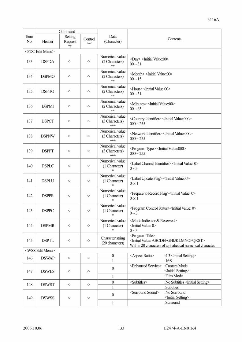
3116A
2006.10.06 E2474-A-EN01R4 133
Command
Item No. Header
Setting Request
‘?’
Control ‘=’
Data (Character) Contents
<PDC Edit Menu>
133 DSPDA Numerical value(2 Characters)
**
<Day> <Initial Value:00> 00 ~ 31
134 DSPMO Numerical value(2 Characters)
**
<Month> <Initial Value:00> 00 ~ 15
135 DSPHO Numerical value(2 Characters)
**
<Hour> <Initial Value:00> 00 ~ 31
136 DSPMI Numerical value(2 Characters)
**
<Minutes> <Initial Value:00> 00 ~ 63
137 DSPCT Numerical value(3 Characters)
***
<Country Identifier> <Initial Value:000> 000 ~ 255
138 DSPNW Numerical value(3 Characters)
***
<Network Identifier> <Initial Value:000> 000 ~ 255
139 DSPPT Numerical value(3 Characters)
***
<Program Type> <Initial Value:000> 000 ~ 255
140 DSPLC Numerical value
(1 Character) *
<Label Channel Identifier> <Initial Value: 0> 0 ~ 3
141 DSPLU Numerical value
(1 Character) *
<Label Update Flag> <Initial Value: 0> 0 or 1
142 DSPPR Numerical value
(1 Character) *
<Prepare to Record Flag><Initial Value: 0> 0 or 1
143 DSPPC Numerical value
(1 Character) *
<Program Control Status><Initial Value: 0> 0 ~ 3
144 DSPMR Numerical value
(1 Character) *
<Mode Indicator & Reserved> <Initial Value: 0> 0 ~ 3
145 DSPTL Character string(20 characters)
<Program Title> <Initial Value: ABCDEFGHIJKLMNOPQRST> Within 20 characters of alphabetical numerical character.
<WSS Edit Menu> 0 <Aspect Ratio> :4:3 <Initial Setting> 146 DSWAP 1 :16:9
0 <Enhanced Service> :Camera Mode <Initial Setting> 147 DSWES
1 :Film Mode 0 <Subtitles> :No Subtitles <Initial Setting> 148 DSWST 1 :Subtitles
0 <Surround Sound> :No Surround <Initial Setting> 149 DSWSS
1 :Surround

3116A
2006.10.06 E2474-A-EN01R4 134
Command
Item No. Header
Setting Request
‘?’
Control ‘=’
Data (Character) Contents
<WSS Manual Setting>
150 DSWM2
Hexadecimal numerical value(4 Characters)
****
<Initial Value:0000> [0x]0000 ~ [0x]3FFF
Caution point in case that plural commands are batch transmitted in batch by using “,” (Comma) In case that TV System (“SYSTV=” command) and AUDIO System (“AUDIO=” command) are coupled and transmitted, send “SYSTV=” command and “AUDIO=” at first. (Refer to following.) · In case that “SYSTV=” command and “AUDIO=” are included
SYSTV+=+Blank+Data+, +AUDIO+=+Blank+Data+, +Command+= ...
· In case that only “SYSTV=” command is included SYSTV+=+Blank+Data+, +Command+= ...
· In case that only “AUDIO=” is included AUDIO+=+Blank+Data+, +Command+= ...
Only command which is selected from each commands of AUDIO system (AM/FM, NICAM, A2, JAPAN and BTSC) by “AUDIO” command is valid. If command which is not adapted to selected Audio system at present is transmitted, command error is issued.
List 7.4-2
Command Item No. Header
Setting Request
‘?’
Control ‘=’
Data (Character) Contents
“MEMORY”
151 STORE Numerical value(2 Characters)
**
<MEMORY STORE> 00 ~ 99
152 RECAL Numerical value(2 Characters)
**
<MEMORY RECAL> 00 ~ 99
“CONDITION”
153 STATE Device Information is replied. (*33) Refer to item “7.4.1 Device Information”.
154 IDNRQ (*34) This is command for requesting ID. (*33)
Refer to item “7.4.2 ID Information”. L Local 155 REMTE R Remote
(*33) This is used at only “Setting Value Information and Status Request”. (*34) GP-IB interface does not have this command.

3116A
2006.10.06 E2474-A-EN01R4 135
7.4.1 Device Information
This is used only in acquiring Device information of 3116A.
List 7.4.1 Character No. Contents Configuring Character
1 Initialization Information, Initialization of equipment 2 Alarm Information: FAN 3 Alarm Information: 1st LO 4 Alarm Information: 2nd LO 5 Alarm Information: RF Output 6 Alarm Information: Video Sync Level 7 Alarm Information: Video Input
“0”: Normal “1”: Abnormal
<Example> In case that all device information is normal. STATE=0000000
7.4.2 ID Information
Excluding GP-IB Interface <Response Data> 4 fields divided by comma are replied. IDNRQ= “Field 1”, “Field 2”, “Field 3”, “Field 4” “Field 1” = EIDEN (Manufacture’s Name) “Field 2” = 3116A (Model Name) “Field 3” = 0 (Serial No. (0 fixed.)) “Field 4” = ROM version No. <Example> “IDNRQ=EIDEN,3116A,0,25.5”
7.4.3 Contents List of Response Reply
Excluding GP-IB Interface
Table 7.4.3 Character No. Contents Configuring Character
1 Command Error 2 Parameter Error 3 Busy Error
“0”: Normal “1”: Abnormal
<Example> In case that all response replay contents is normal. RVOPE=000
During reception of “Busy Error”, the next command is impossible to accept.

3116A
2006.10.06 E2474-A-EN01R4 136
7.4.4 Special Remarks of GP-IB Interface 1. When this unit receives transmission request (MTA) under the condition that “Setting Value Information and Status
Request” has never been received after booting, unit name “3116” is replied.
2. When this unit receives transmission request (MTA) after receiving “Setting Value Information and Status Request”, information of corresponding item is replied. Also, information of corresponded item finally received is replied unless receiving item is changed by “Setting value information and status request”
Caution! Do not use simultaneously remote control at connecting more than 2 interfaces with this unit. In the case, failure, such as communication error and etc., is occurred. In case more than 2 interface are connected in usage, restrict that only one interface is used for communication surely.

3116A
2006.10.06 E2474-A-EN01R4 137
8. Reference Data 8.1 Measuring Method of Video Modulation Degree
In general, video modulation degree is measured in one of following 3 methods: - Use of spectrum analyzer - Use of standard TV demodulator - Measurement in form of envelope waveform by using synchroscope Video modulation degree can be obtained by calculation using figure shown in succeeding item. Video signal is wideband composite signal, so that in order to measure peak level accurately it is necessary to take care for bandwidth, amplitude, etc., of measuring instrument to be used.
8.1.1 Measurement of Modulation Degree by Using a Spectrum Analyzer
Various types of measuring instruments may be used for TV signal measurements, but method of measurement by using spectrum analyzer which is currently supposed to be essential for TV signal management is described here. For measuring AM modulation degree by using spectrum analyzer, proceed as follows: (1) Set the bandwidth to maximum. (2) Set the carrier to be measured at the center frequency. (3) Set the screen to the linear scale mode. (4) Adjust the peak value of the carrier wave at the uppermost portion on the screen. (5) Set the scanning condition gradually to zero scan. (6) Finely adjust the center frequency. Obtain the peak value. (7) Finely adjust again the peak value at the uppermost portion on the screen. Then, such waveform as shown below appears on spectrum analyzer.
Unless frequency which indicates peak value of modulated video signal in measuring modulation degree is sufficiently lower than VBW of spectrum analyzer in use, major errors may be caused. In the case of, for instance, spectrum analyzer with VBW of 300 kHz, color subcarrier of 3.58 MHz falls off and only Y component of peak value of video signal appears.
100_degree(%)Modulation ×−
=A
BA

3116A
2006.10.06 E2474-A-EN01R4 138
8.1.2 Measurement by Substitution Method In measurement of modulation degree by using spectrum analyzer, it is not possible to accurately measure modulation degree unless bandwidth of spectrum analyzer exceeds 5 MHz. When measuring modulation degree by using spectrum analyzer, substitution method is used in which video signal is modulated with signal having low frequency component representing peak value of video signal (Such as white signal, monoscope signal and etc.), then modulation degree is measured, and later video signal of white signal or like is replaced with signal to be used actually. Example of Measurement is shown in below. (1) For video signal, provide white signal. (2) Set amplitude width accurately at 1 Vp-p (75 Ω termination) by using oscilloscope. (3) Modulate TV modulator. (4) Set video modulation degree of TV modulator at 87.5 % while measuring on spectrum analyzer.
(5) Replace video signal of white signal to a color bar signal or a like. (6) At this time, set color bar signal at 1 Vp-p as in the case of white signal. (7) Apply color bar signal to 3116A TV Modulator. (8) Do not change modulation degree of TV modulator but keep it as set in step (4) above. By this, TV modulator is set to modulation degree of 87.5 % with the color bar signal. Of course, there is no problem at all if color bar signal containing 100 % white (IQ) is measured on 100 % white signal portion by directly using spectrum analyzer.
%5.8710080
1080
10B80A
=×−
==
A
B

3116A
2006.10.06 E2474-A-EN01R4 139
8.2 Measuring Method of Audio FM Modulation Degree In general, Bessel Null Method is used for measuring FM modulation degree (frequency deviation). Through calculation of Bessel Null of frequency deviation of ±25 kHz in the case of M system (Refer to next item for Bessel Null Method), we have, 1st: 10.396 MHz, 2nd: 4.529 kHz and 3rd: 2.889 kHz. Here, 4.529 kHz (2nd) is used. (1) Adjust output frequency of audio oscillator accurately at 4.529 kHz by using frequency counter ant etc. and output level at 0 dBm (600 Ω termination). (2) Apply input at [WIDE] terminal of 3116A. (3) Set pre-emphasis to "OFF." (4) Set FM modulation degree at 25 kHz. (5) Set spectrum analyzer as follows: Center Frequency: 34.4 MHz On Screen: Linear scale SPAN: 5 kHz VBW: 300 Hz (6) Then, such waveform as shown in [Fig. 1] appears on spectrum analyzer. If frequency deviation is accurately ±25 kHz, carrier is in minimum (NULL POINT) condition as shown in [Fig. 2]. If carrier is remained, set carrier to [NULL POINT] by offsetting the FM audio modulation degree as in the case of offset operation of video modulation degree. * Bessel Null Method m = Modulation Index, fm = Modulation Frequency (Hz), ∆fpeak = Max. Frequency Deviation (Hz) m =∆fpeak / fm
FM Peak Deviation Value Zero's order
Modulation Index 7.5
kHz 10 kHz
15 kHz
25 kHz
30 kHz
50 kHz
75 kHz
100 kHz
150 kHz
250 kHz
300 kHz
1 2.40 3.13 4.17 6.25 10.42 12.50 20.83 31.25 41.67 62.50 104.2 125.0 2 5.52 1.36 1.81 2.72 4.53 5.43 9.06 13.59 18.12 27.17 45.29 54.35 3 8.65 0.87 1.16 1.73 2.89 3.47 5.78 8.67 11.56 17.34 28.90 34.68 4 11.79 0.64 0.85 1.27 2.12 2.54 4.24 6.36 8.48 12.72 21.20 25.45 5 14.93 0.50 0.67 1.00 1.67 2.01 3.35 5.02 6.70 10.05 16.74 20.09 6 18.07 0.42 0.55 0.83 1.38 1.66 2.77 4.15 5.53 8.30 13.84 16.60 Modulation frequency (kHz) Fig. 1 When modulation is shallow Fig. 2 When carrier is "0"

3116A
2006.10.06 E2474-A-EN01R4 140
8.3 Measuring Method of Audio AM Modulation Degree Although video AM modulation degree is measured as stated in item 8.1, equation for calculation of audio AM modulation degree is somewhat different from that of video AM modulation degree and is as follows:
For this measurement, spectrum analyzer is used. Setting of spectrum analyzer is identical as used for measurement of video modulation degree. (1) Set carrier to be measured at center frequency. (2) Put screen into a linear scale. (3) Adjust peak value of carrier at uppermost portion on screen. (4) Gradually adjust SPAN at zero. (5) Finely adjust center frequency. (6) Finely adjust peak value at uppermost portion on screen. (7) Then, such waveform as shown below appears on spectrum analyzer.
Modulation Degree = At 50 %
B A 】
A
A-B【
A+B
A-B)(
100deg_mod_
100%deg_mod
×=
×=
reeulationVideo
reeulation
B
A
Modulation Degree (%) = x 100A - BA + B

3116A
2006.10.06 E2474-A-EN01R4 141
8.4 TV System of the World (Reference Materials) 8.4.1 CCIR (M, N) SYSTEM
AMPLITUDE (%)
100
10
30
20
50
0
-4 -3 -2-5 -1 0 1 2 3 4 5 6 7
FREQUENCY(MHz)
-fs
(-3.58) (-1.25) (-0.5)
(-0.75)
+2
0
-2
-4
-6
-8
-10
-12
-14
-16
-18
-20
ATTENUATION(dB)
fv
(-1.5)
(3.58)
fs
(4.5)
fa
(4.18) (4.75)
(-42dB)
CCIR(M,N) SYSTEM RF SIDEBAND SPECTRUM
+100
0
-100
-200
-300
-400
-500
DELAY TIME(mμs)
FREQUENCY(MHz)
0 0.5 1 2 3 4(2.1)(0.2) (3.58) (4.18)
(+70)
(-70)(-60)
(-110)(-120)
(+30)
(-30)
(+50)
(-50)
(+50)
(-50)
(-120)(-140)
(-170)
(-220)(-246)(-276)
(-346)
(-416)
(-446)
LAW OF JAPAN
DSS
FLATCHARACTERISTIC
RECEIVINGCHARACTERISTIC
DSS RECEPTION
5 6
CCIR(M,N) SYSTEM GROUP DELAY

3116A
2006.10.06 E2474-A-EN01R4 142
8.4.2 CCIR (B/G) SYSTEM
AMPLITUDE (%)
100
10
30
20
50
0
-4 -3 -2-5 -1 0 1 2 3 4 5 6 7
FREQUENCY(MHz)
-fs
(-4.43) (-1.25) (-0.5)
(-0.75)
+2
0
-2
-4
-6
-8
-10
-12
-14
-16
-18
-20
ATTENUATION(dB)
fv
(-1.5)
(4.43)
fs
(5.5)
fa
(-40dB 以上)
CCIR(B,G) SYSTEM RF SIDEBAND SPECTRUM
+100
0
-100
-200
-300
-400
-500
DELAY TIME(mμs)
FREQUENCY(MHz)
0 0.5 1 2 3 4(0.25) (3.75) (4.43)
(+90)
(-90)
(+25)
(-25)
(+75)
(0)
(-175)
FLATCHARACTERISTIC
RECEIVINGCHARACTERISTIC
(4.8) 5
(+50)
(-50)
(+5)
(+53)
(+90)
6
CCIR(B,G) SYSTEM GROUP DELAY

3116A
2006.10.06 E2474-A-EN01R4 143
8.4.3 CCIR (B) SYSTEM (AUSTRALIA)
AMPLITUDE (%)
100
10
30
20
50
0
-4 -3 -2-5 -1 0 1 2 3 4 5 6 7
FREQUENCY(MHz)
-fs
(-4.43) (-1.25) (-0.5)
(-0.75)
+2
0
-2
-4
-6
-8
-10
-12
-14
-16
-18
-20
ATTENUATION(dB)
fv
(-1.5)
(4.43)
fs
(5.5)
fa
(-40dB 以上)
CCIR(B,G) SYSTEM(AUSTRALIA) RF SIDEBAND SPECTRUM
+100
0
-100
-200
-300
-400
-500
DELAY TIME(mμs)
FREQUENCY(MHz)
0 0.5 1 2 3 4(0.2) (2.4) (4.43)
(+25)
(-25)
(+60)
(0)
(-80)
FLATCHARACTERISTIC
RECEIVINGCHARACTERISTIC
(4.8) 5
(+50)
(-50)
(+7)(+25)
(+55)
6
CCIR(B,G) SYSTEM(AUSTRALIA) GROUP DELAY
(+40)
(-170)
(-230)(-260)

3116A
2006.10.06 E2474-A-EN01R4 144
8.4.4 CCIR (D/K) SYSTEM
AMPLITUDE (%)
100
10
30
20
50
0
-4 -3 -2-5 -1 0 1 2 3 4 5 6 7
FREQUENCY(MHz)
-fs
(-4.43) (-1.25) (-0.5)
(-0.75)
+2
0
-2
-4
-6
-8
-10
-12
-14
-16
-18
-20
ATTENUATION(dB)
fv
(4.43)
fs
(6.5)
fa
(-30dB)
CCIR(D,K) SYSTEM RF SIDEBAND SPECTRUM
(5.25)
NORM
+100
0
-100
-200
-300
-400
-500
DELAY TIME(mμs)
FREQUENCY(MHz)
0 0.5 1 2 3 4(0.25) (4.43)
(+25)
(-25)
(+80)
(-80)
FLATCHARACTERISTIC
RECEIVINGCHARACTERISTIC
5
(+50)
(-50)
(+2.2) (+40)
6
CCIR(D,K) SYSTEM GROUP DELAY
(+10)
(+70) (+80)
(+40)

3116A
2006.10.06 E2474-A-EN01R4 145
8.4.5 CCIR-D (CHINA) SYSTEM
AMPLITUDE (%)
100
10
30
20
50
0
-4 -3 -2-5 -1 0 1 2 3 4 5 6 7
FREQUENCY(MHz)
-fs
(-4.43) (-1.25) (-0.5)
(-0.75)
+2
0
-2
-4
-6
-8
-10
-12
-14
-16
-18
-20
ATTENUATION(dB)
fv
(4.43)
fs
(6.5)
fa
(-30dB)
CCIR-D(CHINA) SYSTEM RF SIDEBAND SPECTRUM
(5.25)
NORM
+100
0
-100
-200
-300
-400
-500
DELAY TIME(mμs)
FREQUENCY(MHz)
0 0.5 1 2 3 4(0.25) (4.43)
(+20)
(-20)
FLATCHARACTERISTIC
5
(+40)
(-40)
6
CCIR-D(CHINA) SYSTEM GROUP DELAY
(2.97) (5.89)
(+80)
(-80)

3116A
2006.10.06 E2474-A-EN01R4 146
8.4.6 CCIR-D (CHINA) SYSTEM in Combination with NICAM
AMPLITUDE (%)
100
10
30
20
50
0
-4 -3 -2-5 -1 0 1 2 3 4 5 6 7
FREQUENCY(MHz)
-fs
(-4.43) (-1.25) (-0.5)
(-0.75)
+2
0
-2
-4
-6
-8
-10
-12
-14
-16
-18
-20
ATTENUATION(dB)
fv
(4.43)
fs
(6.5)
fa
(-30dB)
CCIR-D(CHINA) SYSTEM RF SIDEBAND SPECTRUM + NICAM
(5.1)
NORM
(5.6)
(5.85)(-30dB)
+100
0
-100
-200
-300
-400
-500
DELAY TIME(mμs)
FREQUENCY(MHz)
0 0.5 1 2 3 4(0.25) (4.43)
(+20)
(-20)
FLATCHARACTERISTIC
5
(+40)
(-40)
6
CCIR-D(CHINA) SYSTEM GROUP DELAY + NICAM
(2.97) (5.89)
(+80)
(-80)

3116A
2006.10.06 E2474-A-EN01R4 147
8.4.7 CCIR (I) SYSTEM
AMPLITUDE (%)
100
10
30
20
50
0
-4 -3 -2-5 -1 0 1 2 3 4 5 6 7
FREQUENCY(MHz)
-fs
(-4.43)
+2
0
-2
-4
-6
-8
-10
-12
-14
-16
-18
-20
ATTENUATION(dB)
fv
(4.43)
fs fa
(-30dB 以上)
CCIR(I) SYSTEM RF SIDEBAND SPECTRUM
(5.5)
fc
(4.5)
+100
0
-100
-200
-300
-400
-500
DELAY TIME(mμs)
FREQUENCY(MHz)
0 0.5 1 2 3 4(0.25) (4.43)
(+25)
(-25)
FLATCHARACTERISTIC
5
(+40)
(-40)
6
CCIR(I) SYSTEM GROUP DELAY
(+80)
(-80)

3116A
2006.10.06 E2474-A-EN01R4 148
8.4.8 CCIR (L) SYSTEM
AMPLITUDE (%)
100
10
30
20
50
0
-4 -3 -2-5 -1 0 1 2 3 4 5 6 7
FREQUENCY(MHz)
+2
0
-2
-4
-6
-8
-10
-12
-14
-16
-18
-20
ATTENUATION(dB)
fv fa
CCIR(L) SYSTEM RF SIDEBAND SPECTRUM
(-1.25)(-1.75)
(-2.25)(-2.75)
(-15)
(-2.125)
(-5)
(6.5)
+100
0
-100
-200
-300
-400
-500
DELAY TIME(mμs)
FREQUENCY(MHz)
0 0.5 1 2 3 4(0.25) (4.43)
(+30)
(-30)
FLATCHARACTERISTIC
5
(+60)
(-60)
6
CCIR(L) SYSTEM GROUP DELAY
(4.8)
(+60)
(-60)
(5.25)
RECEIVINGCHARACTERISTIC
(4.6)
(0)
(-20)
(-57.5)
(-100)

3116A
2006.10.06 E2474-A-EN01R4 149
8.4.9 CCIR (L) SYSTEM in Combination with NICAM
AMPLITUDE (%)
100
10
30
20
50
0
-4 -3 -2-5 -1 0 1 2 3 4 5 6 7
FREQUENCY(MHz)
+2
0
-2
-4
-6
-8
-10
-12
-14
-16
-18
-20
ATTENUATION(dB)
fv fa
CCIR(L) SYSTEM RF SIDEBAND SPECTRUM + NICAM
(-1.25)(-1.75)
(-2.25)(-2.75)
(-15)
(-2.125)
(-5)
(6.5)(5.1)
(5.85)(-30dB)
(5.6)
+100
0
-100
-200
-300
-400
-500
DELAY TIME(mμs)
FREQUENCY(MHz)
0 0.5 1 2 3 4(0.25) (4.43)
(+30)
(-30)
FLATCHARACTERISTIC
5
(+60)
(-60)
6
CCIR(L) SYSTEM GROUP DELAY + NICAM
(4.8)
(+60)
(-60)
(5.25)
RECEIVINGCHARACTERISTIC
(4.6)
(0)
(-20)
(-57.5)
(-100)

3116A
2006.10.06 E2474-A-EN01R4 150
8.5 Setting Channel List of This Unit 8.5.1 Selection of Country / Area
List 8.5.1 VIDEO System
NTSC4.43 PAL SECAM Item No.
Country /Area NTSC
M B/G D/K I B/G I D N M D (CHINA)
B (AUS) B/G D/K L
1 Italy
2 New Zealand
3 Morocco 4 Europe
5 Europe CATV
6 Australia 7 OIRT 8 China
9 China CATV
10 Ireland
11 South Africa
12 Angola 13 France
14 U.S.A.
15 U.S.A. CATV
16 KOREA
17 KOREA CATV
18 JAPAN
19 JAPAN CATV
sign: Possible to select. In case that the RF output frequency indication setting is set to “Channel”, “Sideband” is impossible to operate. The sidebands of Country / Area: France “FR-A”, “FR-B”, “FR-C” and “FR-C1” are fixed to “Lower” and the sidebands of the other channels are fixed to “Upper”.

3116A
2006.10.06 E2474-A-EN01R4 151
8.5.2 Channel List Country / Area: Italy Country / Area: New Zealand Vision Vision
[MHz] [MHz]IT-A 53.75 B-58 767.25IT-B 62.25 B-59 775.25IT-C 82.25 B-60 783.25IT-D 175.25 B-61 791.25IT-E 183.75 B-62 799.25IT-F 192.25 B-63 807.25IT-G 201.25 B-64 815.25IT-H 210.25 B-65 823.25IT-H1 217.25 B-66 831.25IT-H2 224.25 B-67 839.25B-21 471.25 B-68 847.25B-22 479.25 B-69 855.25B-23 487.25 B-70 863.25B-24 495.25 B-71 871.25B-25 503.25 B-72 879.25B-26 511.25 B-73 887.25B-27 519.25 B-74 895.25B-28 527.25B-29 535.25B-30 543.25B-31 551.25B-32 559.25B-33 567.25B-34 575.25B-35 583.25B-36 591.25B-37 599.25B-38 607.25B-39 615.25B-40 623.25B-41 631.25B-42 639.25B-43 647.25B-44 655.25B-45 663.25B-46 671.25B-47 679.25B-48 687.25B-49 695.25B-50 703.25B-51 711.25B-52 719.25B-53 727.25B-54 735.25B-55 743.25B-56 751.25B-57 759.25
ChannelNumber
ChannelNumber
Vision Vision[MHz] [MHz]
NZ-1 45.25 B-58 767.25NZ-2 55.25 B-59 775.25NZ-3 62.25 B-60 783.25NZ-4 175.25 B-61 791.25NZ-5 182.25 B-62 799.25NZ-6 189.25 B-63 807.25NZ-7 196.25 B-64 815.25NZ-8 203.25 B-65 823.25NZ-9 210.25 B-66 831.25NZ-10 217.25 B-67 839.25B-21 471.25 B-68 847.25B-22 479.25 B-69 855.25B-23 487.25 B-70 863.25B-24 495.25 B-71 871.25B-25 503.25 B-72 879.25B-26 511.25 B-73 887.25B-27 519.25 B-74 895.25B-28 527.25B-29 535.25B-30 543.25B-31 551.25B-32 559.25B-33 567.25B-34 575.25B-35 583.25B-36 591.25B-37 599.25B-38 607.25B-39 615.25B-40 623.25B-41 631.25B-42 639.25B-43 647.25B-44 655.25B-45 663.25B-46 671.25B-47 679.25B-48 687.25B-49 695.25B-50 703.25B-51 711.25B-52 719.25B-53 727.25B-54 735.25B-55 743.25B-56 751.25B-57 759.25
ChannelNumber
ChannelNumber

3116A
2006.10.06 E2474-A-EN01R4 152
Country / Area: Morocco Vision Vision
[MHz] [MHz]MA-M4 163.25 B-61 791.25MA-M5 171.25 B-62 799.25MA-M6 179.25 B-63 807.25MA-M7 187.25 B-64 815.25MA-M8 195.25 B-65 823.25MA-M9 203.25 B-66 831.25
MA-M10 211.25 B-67 839.25B-21 471.25 B-68 847.25B-22 479.25 B-69 855.25B-23 487.25 B-70 863.25B-24 495.25 B-71 871.25B-25 503.25 B-72 879.25B-26 511.25 B-73 887.25B-27 519.25 B-74 895.25B-28 527.25B-29 535.25B-30 543.25B-31 551.25B-32 559.25B-33 567.25B-34 575.25B-35 583.25B-36 591.25B-37 599.25B-38 607.25B-39 615.25B-40 623.25B-41 631.25B-42 639.25B-43 647.25B-44 655.25B-45 663.25B-46 671.25B-47 679.25B-48 687.25B-49 695.25B-50 703.25B-51 711.25B-52 719.25B-53 727.25B-54 735.25B-55 743.25B-56 751.25B-57 759.25B-58 767.25B-59 775.25B-60 783.25
ChannelNumber
ChannelNumber

3116A
2006.10.06 E2474-A-EN01R4 153
Country / Area: Europe Country / Area: Europe CATV Vision Vision
[MHz] [MHz]E-2 48.25 E-57 759.25E-3 55.25 E-58 767.25E-4 62.25 E-59 775.25E-5 175.25 E-60 783.25E-6 182.25 E-61 791.25E-7 189.25 E-62 799.25E-8 196.25 E-63 807.25E-9 203.25 E-64 815.25
E-10 210.25 E-65 823.25E-11 217.25 E-66 831.25E-12 224.25 E-67 839.25E-21 471.25 E-68 847.25E-22 479.25 E-69 855.25E-23 487.25 E-70 863.25E-24 495.25 E-71 871.25E-25 503.25 E-72 879.25E-26 511.25 E-73 887.25E-27 519.25 E-74 895.25E-28 527.25E-29 535.25E-30 543.25E-31 551.25E-32 559.25E-33 567.25E-34 575.25E-35 583.25E-36 591.25E-37 599.25E-38 607.25E-39 615.25E-40 623.25E-41 631.25E-42 639.25E-43 647.25E-44 655.25E-45 663.25E-46 671.25E-47 679.25E-48 687.25E-49 695.25E-50 703.25E-51 711.25E-52 719.25E-53 727.25E-54 735.25E-55 743.25E-56 751.25
ChannelNumber
ChannelNumber
Vision Vision[MHz] [MHz]
E-2 48.25 E-S32 391.25E-3 55.25 E-S33 399.25E-4 62.25 E-S34 407.25
E-S01 69.25 E-S35 415.25E-S02 76.25 E-S36 423.25E-S03 83.25 E-S37 431.25E-Z+1 90.25 E-S38 439.25E-Z+2 97.25 E-S39 447.25E-S1 105.25 E-S40 455.25E-S2 112.25 E-S41 463.25E-S3 119.25E-S4 126.25E-S5 133.25E-S6 140.25E-S7 147.25E-S8 154.25E-S9 161.25E-S10 168.25
E-5 175.25E-6 182.25E-7 189.25E-8 196.25E-9 203.25
E-10 210.25E-11 217.25E-12 224.25
E-S11 231.25E-S12 238.25E-S13 245.25E-S14 252.25E-S15 259.25E-S16 266.25E-S17 273.25E-S18 280.25E-S19 287.25E-S20 294.25E-S21 303.25E-S22 311.25E-S23 319.25E-S24 327.25E-S25 335.25E-S26 343.25E-S27 351.25E-S28 359.25E-S29 367.25E-S30 375.25E-S31 383.25
ChannelNumber
ChannelNumber

3116A
2006.10.06 E2474-A-EN01R4 154
Country / Area: Australia Country / Area: OIRT Vision
[MHz]AU-0 46.25AU-1 57.25AU-2 64.25AU-3 86.25AU-4 95.25AU-5 102.25
AU-5A 138.25AU-6 175.25AU-7 182.25AU-8 189.25AU-9 196.25
AU-9A 203.25AU-10 210.25AU-11 217.25AU-12 224.25
ChannelNumber
Vision Vision[MHz] [MHz]
R-1 49.75 R-56 751.25R-2 59.25 R-57 759.25R-3 77.25 R-58 767.25R-4 85.25 R-59 775.25R-5 93.25 R-60 783.25R-6 175.25 R-61 791.25R-7 183.25 R-62 799.25R-8 191.25 R-63 807.25R-9 199.25 R-64 815.25R-10 207.25 R-65 823.25R-11 215.25 R-66 831.25R-12 223.25 R-67 839.25R-21 471.25 R-68 847.25R-22 479.25 R-69 855.25R-23 487.25 R-70 863.25R-24 495.25 R-71 871.25R-25 503.25 R-72 879.25R-26 511.25 R-73 887.25R-27 519.25 R-74 895.25R-28 527.25R-29 535.25R-30 543.25R-31 551.25R-32 559.25R-33 567.25R-34 575.25R-35 583.25R-36 591.25R-37 599.25R-38 607.25R-39 615.25R-40 623.25R-41 631.25R-42 639.25R-43 647.25R-44 655.25R-45 663.25R-46 671.25R-47 679.25R-48 687.25R-49 695.25R-50 703.25R-51 711.25R-52 719.25R-53 727.25R-54 735.25R-55 743.25
ChannelNumber
ChannelNumber

3116A
2006.10.06 E2474-A-EN01R4 155
Country / Area: China Country / Area: China CATV Vision Vision
[MHz] [MHz]CN-1 49.75 CN-48 791.25CN-2 57.75 CN-49 799.25CN-3 65.75 CN-50 807.25CN-4 77.25 CN-51 815.25CN-5 85.25 CN-52 823.25CN-6 168.25 CN-53 831.25CN-7 176.25 CN-54 839.25CN-8 184.25 CN-55 847.25CN-9 192.25 CN-56 855.25CN-10 200.25 CN-57 863.25CN-11 208.25 CN-58 871.25CN-12 216.25 CN-59 879.25CN-13 471.25 CN-60 887.25CN-14 479.25 CN-61 895.25CN-15 487.25CN-16 495.25CN-17 503.25CN-18 511.25CN-19 519.25CN-20 527.25CN-21 535.25CN-22 543.25CN-23 551.25CN-24 559.25CN-25 607.25CN-26 615.25CN-27 623.25CN-28 631.25CN-29 639.25CN-30 647.25CN-31 655.25CN-32 663.25CN-33 671.25CN-34 679.25CN-35 687.25CN-36 695.25CN-37 703.25CN-38 711.25CN-39 719.25CN-40 727.25CN-41 735.25CN-42 743.25CN-43 751.25CN-44 759.25CN-45 767.25CN-46 775.25CN-47 783.25
ChannelNumber
ChannelNumber
Vision Vision[MHz] [MHz]
CN-Z1 112.25 CN-DS16 495.25CN-Z2 120.25 CN-DS17 503.25CN-Z3 128.25 CN-DS18 511.25CN-Z4 136.25 CN-DS19 519.25CN-Z5 144.25 CN-DS20 527.25CN-Z6 152.25 CN-DS21 535.25CN-Z7 160.25 CN-DS22 543.25
CN-DS6 168.25 CN-DS23 551.25CN-DS7 176.25 CN-DS24 559.25CN-DS8 184.25 CN-Z38 567.25CN-DS9 192.25 CN-Z39 575.25
CN-DS10 200.25 CN-Z40 583.25CN-DS11 208.25 CN-Z41 591.25CN-DS12 216.25 CN-Z42 599.25
CN-Z8 224.25 CN-DS25 607.25CN-Z9 232.25 CN-DS26 615.25CN-Z10 240.25 CN-DS27 623.25CN-Z11 248.25 CN-DS28 631.25CN-Z12 256.25 CN-DS29 639.25CN-Z13 264.25 CN-DS30 647.25CN-Z14 272.25 CN-DS31 655.25CN-Z15 280.25 CN-DS32 663.25CN-Z16 288.25 CN-DS33 671.25CN-Z17 296.25 CN-DS34 679.25CN-Z18 304.25 CN-DS35 687.25CN-Z19 312.25 CN-DS36 695.25CN-Z20 320.25 CN-DS37 703.25CN-Z21 328.25 CN-DS38 711.25CN-Z22 336.25 CN-DS39 719.25CN-Z23 344.25 CN-DS40 727.25CN-Z24 352.25 CN-DS41 735.25CN-Z25 360.25 CN-DS42 743.25CN-Z26 368.25 CN-DS43 751.25CN-Z27 376.25 CN-DS44 759.25CN-Z28 384.25 CN-DS45 767.25CN-Z29 392.25 CN-DS46 775.25CN-Z30 400.25 CN-DS47 783.25CN-Z31 408.25 CN-DS48 791.25CN-Z32 416.25 CN-DS49 799.25CN-Z33 424.25 CN-DS50 807.25CN-Z34 432.25 CN-DS51 815.25CN-Z35 440.25 CN-DS52 823.25CN-Z36 448.25 CN-DS53 831.25CN-Z37 456.25 CN-DS54 839.25
CN-DS13 471.25 CN-DS55 847.25CN-DS14 479.25 CN-DS56 855.25CN-DS15 487.25
ChannelNumber
ChannelNumber

3116A
2006.10.06 E2474-A-EN01R4 156
Country / Area: Ireland Country / Area: South Africa Vision Vision
[MHz] [MHz]IE-IA 45.75 I-59 775.25IE-IB 53.75 I-60 783.25IE-IC 61.75 I-61 791.25IE-ID 175.25 I-62 799.25IE-IE 183.25 I-63 807.25IE-IF 191.25 I-64 815.25IE-IG 199.25 I-65 823.25IE-IH 207.25 I-66 831.25IE-IJ 215.25 I-67 839.25I-21 471.25 I-68 847.25I-22 479.25 I-69 855.25I-23 487.25 I-70 863.25I-24 495.25 I-71 871.25I-25 503.25 I-72 879.25I-26 511.25 I-73 887.25I-27 519.25 I-74 895.25I-28 527.25I-29 535.25I-30 543.25I-31 551.25I-32 559.25I-33 567.25I-34 575.25I-35 583.25I-36 591.25I-37 599.25I-38 607.25I-39 615.25I-40 623.25I-41 631.25I-42 639.25I-43 647.25I-44 655.25I-45 663.25I-46 671.25I-47 679.25I-48 687.25I-49 695.25I-50 703.25I-51 711.25I-52 719.25I-53 727.25I-54 735.25I-55 743.25I-56 751.25I-57 759.25I-58 767.25
ChannelNumber
ChannelNumber
Vision Vision[MHz] [MHz]
ZA-4 175.25 I-59 775.25ZA-5 183.25 I-60 783.25ZA-6 191.25 I-61 791.25ZA-7 199.25 I-62 799.25ZA-8 207.25 I-63 807.25ZA-9 215.25 I-64 815.25
ZA-10 223.25 I-65 823.25ZA-11 231.25 I-66 831.25ZA-12 239.25 I-67 839.25I-21 471.25 I-68 847.25I-22 479.25 I-69 855.25I-23 487.25 I-70 863.25I-24 495.25 I-71 871.25I-25 503.25 I-72 879.25I-26 511.25 I-73 887.25I-27 519.25 I-74 895.25I-28 527.25I-29 535.25I-30 543.25I-31 551.25I-32 559.25I-33 567.25I-34 575.25I-35 583.25I-36 591.25I-37 599.25I-38 607.25I-39 615.25I-40 623.25I-41 631.25I-42 639.25I-43 647.25I-44 655.25I-45 663.25I-46 671.25I-47 679.25I-48 687.25I-49 695.25I-50 703.25I-51 711.25I-52 719.25I-53 727.25I-54 735.25I-55 743.25I-56 751.25I-57 759.25I-58 767.25
ChannelNumber
ChannelNumber

3116A
2006.10.06 E2474-A-EN01R4 157
Country / Area: Angola Country / Area: France Vision Vision
[MHz] [MHz]AO-1 43.25 I-59 775.25AO-2 52.25 I-60 783.25AO-3 60.25 I-61 791.25AO-4 175.25 I-62 799.25AO-5 183.25 I-63 807.25AO-6 191.25 I-64 815.25AO-7 199.25 I-65 823.25AO-8 207.25 I-66 831.25AO-9 215.25 I-67 839.25I-21 471.25 I-68 847.25I-22 479.25 I-69 855.25I-23 487.25 I-70 863.25I-24 495.25 I-71 871.25I-25 503.25 I-72 879.25I-26 511.25 I-73 887.25I-27 519.25 I-74 895.25I-28 527.25I-29 535.25I-30 543.25I-31 551.25I-32 559.25I-33 567.25I-34 575.25I-35 583.25I-36 591.25I-37 599.25I-38 607.25I-39 615.25I-40 623.25I-41 631.25I-42 639.25I-43 647.25I-44 655.25I-45 663.25I-46 671.25I-47 679.25I-48 687.25I-49 695.25I-50 703.25I-51 711.25I-52 719.25I-53 727.25I-54 735.25I-55 743.25I-56 751.25I-57 759.25I-58 767.25
ChannelNumber
ChannelNumber
Vision Vision[MHz] [MHz]
FR-A 47.75 FR-58 767.25FR-B 55.75 FR-59 775.25FR-C 63.75 FR-60 783.25
FR-C1 60.50 FR-61 791.25FR-1 176.00 FR-62 799.25FR-2 184.00 FR-63 807.25FR-3 192.00 FR-64 815.25FR-4 200.00 FR-65 823.25FR-5 208.00 FR-66 831.25FR-6 216.00 FR-67 839.25FR-21 471.25 FR-68 847.25FR-22 479.25 FR-69 855.25FR-23 487.25 FR-70 863.25FR-24 495.25 FR-71 871.25FR-25 503.25 FR-72 879.25FR-26 511.25 FR-73 887.25FR-27 519.25 FR-74 895.25FR-28 527.25FR-29 535.25FR-30 543.25FR-31 551.25FR-32 559.25FR-33 567.25FR-34 575.25FR-35 583.25FR-36 591.25FR-37 599.25FR-38 607.25FR-39 615.25FR-40 623.25FR-41 631.25FR-42 639.25FR-43 647.25FR-44 655.25FR-45 663.25FR-46 671.25FR-47 679.25FR-48 687.25FR-49 695.25FR-50 703.25FR-51 711.25FR-52 719.25FR-53 727.25FR-54 735.25FR-55 743.25FR-56 751.25FR-57 759.25
ChannelNumber
ChannelNumber

3116A
2006.10.06 E2474-A-EN01R4 158
Country / Area: U.S.A Vision Vision
[MHz] [MHz]US-2 55.25 US-49 681.25US-3 61.25 US-50 687.25US-4 67.25 US-51 693.25US-5 77.25 US-52 699.25US-6 83.25 US-53 705.25US-7 175.25 US-54 711.25US-8 181.25 US-55 717.25US-9 187.25 US-56 723.25
US-10 193.25 US-57 729.25US-11 199.25 US-58 735.25US-12 205.25 US-59 741.25US-13 211.25 US-60 747.25US-14 471.25 US-61 753.25US-15 477.25 US-62 759.25US-16 483.25 US-63 765.25US-17 489.25 US-64 771.25US-18 495.25 US-65 777.25US-19 501.25 US-66 783.25US-20 507.25 US-67 789.25US-21 513.25 US-68 795.25US-22 519.25 US-69 801.25US-23 525.25 US-70 807.25US-24 531.25 US-71 813.25US-25 537.25 US-72 819.25US-26 543.25 US-73 825.25US-27 549.25 US-74 831.25US-28 555.25 US-75 837.25US-29 561.25 US-76 843.25US-30 567.25 US-77 849.25US-31 573.25 US-78 855.25US-32 579.25 US-79 861.25US-33 585.25 US-80 867.25US-34 591.25 US-81 873.25US-35 597.25 US-82 879.25US-36 603.25 US-83 885.25US-37 609.25US-38 615.25US-39 621.25US-40 627.25US-41 633.25US-42 639.25US-43 645.25US-44 651.25US-45 657.25US-46 663.25US-47 669.25US-48 675.25
ChannelNumber
ChannelNumber

3116A
2006.10.06 E2474-A-EN01R4 159
Country / Area: U.S.A. CATV Vision Vision Vision
[MHz] [MHz] [MHz]US-2 55.25 US-H5 343.25 US-C91 625.25US-3 61.25 US-H6 349.25 US-C92 631.25US-4 67.25 US-H7 355.25 US-C93 637.25US-5 77.25 US-H8 361.25 US-C94 643.25US-6 83.25 US-H9 367.25 US-C100 649.25
US-A-5 91.25 US-H10 373.25 US-C101 655.25US-A-4 97.25 US-H11 379.25 US-C102 661.25US-A-3 103.25 US-H12 385.25 US-C103 667.25US-A-2 109.25 US-H13 391.25 US-C104 673.25US-A-1 115.25 US-H14 397.25 US-C105 679.25US-A 121.25 US-H15 403.25 US-C106 685.25US-B 127.25 US-H16 409.25 US-C107 691.25US-C 133.25 US-H17 415.25 US-C108 697.25US-D 139.25 US-H18 421.25 US-C109 703.25US-E 145.25 US-H19 427.25 US-C110 709.25US-F 151.25 US-H20 433.25 US-C111 715.25US-G 157.25 US-H21 439.25 US-C112 721.25US-H 163.25 US-H22 445.25 US-C113 727.25US-I 169.25 US-H23 451.25 US-C114 733.25US-7 175.25 US-H24 457.25 US-C115 739.25US-8 181.25 US-H25 463.25 US-C116 745.25US-9 187.25 US-C65 469.25 US-C117 751.25
US-10 193.25 US-C66 475.25 US-C118 757.25US-11 199.25 US-C67 481.25 US-C119 763.25US-12 205.25 US-C68 487.25 US-C120 769.25US-13 211.25 US-C69 493.25 US-C121 775.25US-J 217.25 US-C70 499.25 US-C122 781.25US-K 223.25 US-C71 505.25 US-C123 787.25US-L 229.25 US-C72 511.25 US-C124 793.25US-M 235.25 US-C73 517.25 US-C125 799.25US-N 241.25 US-C74 523.25 US-C126 805.25US-O 247.25 US-C75 529.25 US-C127 811.25US-P 253.25 US-C76 535.25 US-C128 817.25US-Q 259.25 US-C77 541.25 US-C129 823.25US-R 265.25 US-C78 547.25 US-C130 829.25US-S 271.25 US-C79 553.25 US-C131 835.25US-T 277.25 US-C80 559.25 US-C132 841.25US-U 283.25 US-C81 565.25 US-C133 847.25US-V 289.25 US-C82 571.25 US-C134 853.25US-W 298.25 US-C83 577.25 US-C135 859.25US-X 301.25 US-C84 583.25 US-C136 865.25US-Y 307.25 US-C85 589.25 US-C137 871.25US-Z 313.25 US-C86 595.25 US-C138 877.25
US-H1 319.25 US-C87 601.25 US-C139 883.25US-H2 325.25 US-C88 607.25 US-C140 889.25US-H3 331.25 US-C89 613.25 US-C141 895.25US-H4 337.25 US-C90 619.25
ChannelNumber
ChannelNumber
ChannelNumber

3116A
2006.10.06 E2474-A-EN01R4 160
Country / Area: KOREA Vision Vision
[MHz] [MHz]KR-2 55.25 KR-49 681.25KR-3 61.25 KR-50 687.25KR-4 67.25 KR-51 693.25KR-5 77.25 KR-52 699.25KR-6 83.25 KR-53 705.25KR-7 175.25 KR-54 711.25KR-8 181.25 KR-55 717.25KR-9 187.25 KR-56 723.25
KR-10 193.25 KR-57 729.25KR-11 199.25 KR-58 735.25KR-12 205.25 KR-59 741.25KR-13 211.25 KR-60 747.25KR-14 471.25 KR-61 753.25KR-15 477.25 KR-62 759.25KR-16 483.25 KR-63 765.25KR-17 489.25 KR-64 771.25KR-18 495.25 KR-65 777.25KR-19 501.25 KR-66 783.25KR-20 507.25 KR-67 789.25KR-21 513.25 KR-68 795.25KR-22 519.25 KR-69 801.25KR-23 525.25 KR-70 807.25KR-24 531.25 KR-71 813.25KR-25 537.25 KR-72 819.25KR-26 543.25 KR-73 825.25KR-27 549.25 KR-74 831.25KR-28 555.25 KR-75 837.25KR-29 561.25 KR-76 843.25KR-30 567.25 KR-77 849.25KR-31 573.25 KR-78 855.25KR-32 579.25 KR-79 861.25KR-33 585.25 KR-80 867.25KR-34 591.25 KR-81 873.25KR-35 597.25 KR-82 879.25KR-36 603.25 KR-83 885.25KR-37 609.25KR-38 615.25KR-39 621.25KR-40 627.25KR-41 633.25KR-42 639.25KR-43 645.25KR-44 651.25KR-45 657.25KR-46 663.25KR-47 669.25KR-48 675.25
ChannelNumber
ChannelNumber

3116A
2006.10.06 E2474-A-EN01R4 161
Country / Area: KOREA CATV Vision Vision Vision
[MHz] [MHz] [MHz]KR-2 55.25 KR-C49 373.25 KR-C96 655.25KR-3 61.25 KR-C50 379.25 KR-C97 661.25KR-4 67.25 KR-C51 385.25 KR-C98 667.25KR-5 77.25 KR-C52 391.25 KR-C99 673.25KR-6 83.25 KR-C53 397.25 KR-C100 679.25
KR-C14 121.25 KR-C54 403.25 KR-C101 685.25KR-C15 127.25 KR-C55 409.25 KR-C102 691.25KR-C16 133.25 KR-C56 415.25 KR-C103 697.25KR-C17 139.25 KR-C57 421.25 KR-C104 703.25KR-C18 145.25 KR-C58 427.25 KR-C105 709.25KR-C19 151.25 KR-C59 433.25 KR-C106 715.25KR-C20 157.25 KR-C60 439.25 KR-C107 721.25KR-C21 163.25 KR-C61 445.25 KR-C108 727.25KR-C22 169.25 KR-C62 451.25 KR-C109 733.25
KR-7 175.25 KR-C63 457.25 KR-C110 739.25KR-8 181.25 KR-C64 463.25 KR-C111 745.25KR-9 187.25 KR-C65 469.25
KR-10 193.25 KR-C66 475.25KR-11 199.25 KR-C67 481.25KR-12 205.25 KR-C68 487.25KR-13 211.25 KR-C69 493.25
KR-C23 217.25 KR-C70 499.25KR-C24 223.25 KR-C71 505.25KR-C25 229.25 KR-C72 511.25KR-C26 235.25 KR-C73 517.25KR-C27 241.25 KR-C74 523.25KR-C28 247.25 KR-C75 529.25KR-C29 253.25 KR-C76 535.25KR-C30 259.25 KR-C77 541.25KR-C31 265.25 KR-C78 547.25KR-C32 271.25 KR-C79 553.25KR-C33 277.25 KR-C80 559.25KR-C34 283.25 KR-C81 565.25KR-C35 289.25 KR-C82 571.25KR-C36 298.25 KR-C83 577.25KR-C37 301.25 KR-C84 583.25KR-C38 307.25 KR-C85 589.25KR-C39 313.25 KR-C86 595.25KR-C40 319.25 KR-C87 601.25KR-C41 325.25 KR-C88 607.25KR-C42 331.25 KR-C89 613.25KR-C43 337.25 KR-C90 619.25KR-C44 343.25 KR-C91 625.25KR-C45 349.25 KR-C92 631.25KR-C46 355.25 KR-C93 637.25KR-C47 361.25 KR-C94 643.25KR-C48 367.25 KR-C95 649.25
ChannelNumber
ChannelNumber
ChannelNumber

3116A
2006.10.06 E2474-A-EN01R4 162
Country / Area: JAPAN Country / Area: JAPAN CATV CH other than 50 kHz step and CH more than 900 MHz can not be set. (No description of these CH List)
Vision Vision[MHz] [MHz]
JP-1 91.25 JP-48 681.25JP-2 97.25 JP-49 687.25JP-3 103.25 JP-50 693.25JP-4 171.25 JP-51 699.25JP-5 177.25 JP-52 705.25JP-6 183.25 JP-53 711.25JP-7 189.25 JP-54 717.25JP-8 193.25 JP-55 723.25JP-9 199.25 JP-56 729.25
JP-10 205.25 JP-57 735.25JP-11 211.25 JP-58 741.25JP-12 217.25 JP-59 747.25JP-13 471.25 JP-60 753.25JP-14 477.25 JP-61 759.25JP-15 483.25 JP-62 765.25JP-16 489.25JP-17 495.25JP-18 501.25JP-19 507.25JP-20 513.25JP-21 519.25JP-22 525.25JP-23 531.25JP-24 537.25JP-25 543.25JP-26 549.25JP-27 555.25JP-28 561.25JP-29 567.25JP-30 573.25JP-31 579.25JP-32 585.25JP-33 591.25JP-34 597.25JP-35 603.25JP-36 609.25JP-37 615.25JP-38 621.25JP-39 627.25JP-40 633.25JP-41 639.25JP-42 645.25JP-43 651.25JP-44 657.25JP-45 663.25JP-46 669.25JP-47 675.25
ChannelNumber
ChannelNumber
Vision Vision[MHz] [MHz]
JP-1 91.25 JP-C48 373.25JP-2 97.25 JP-C49 379.25JP-3 103.25 JP-C50 385.25
JP-C13 109.25 JP-C51 391.25JP-C14 115.25 JP-C52 397.25JP-C15 121.25 JP-C53 403.25JP-C16 127.25 JP-C54 409.25JP-C17 133.25 JP-C55 415.25JP-C18 139.25 JP-C56 421.25JP-C19 145.25 JP-C57 427.25JP-C20 151.25 JP-C58 433.25JP-C21 157.25 JP-C59 439.25JP-C22 165.25 JP-C60 445.25
JP-4 171.25 JP-C61 451.25JP-5 177.25 JP-C62 457.25JP-6 183.25 JP-C63 463.25JP-7 189.25JP-8 193.25JP-9 199.25
JP-10 205.25JP-11 211.25JP-12 217.25
JP-C23 223.25JP-C24 231.25JP-C25 237.25JP-C26 243.25JP-C27 249.25JP-C28 253.25JP-C29 259.25JP-C30 265.25JP-C31 271.25JP-C32 277.25JP-C33 283.25JP-C34 289.25JP-C35 295.25JP-C36 301.25JP-C37 307.25JP-C38 313.25JP-C39 319.25JP-C40 325.25JP-C41 331.25JP-C42 337.25JP-C43 343.25JP-C44 349.25JP-C45 355.25JP-C46 361.25JP-C47 367.25
ChannelNumber
ChannelNumber

3116A
2006.10.06 E2474-A-EN01R4 163
9. External View 9.1 Whole View
3116A-002 External View (With LAN OPTION)
420±3
(47)
132±1
(13.5)
(9) 350±2

3116A
2006.10.06 E2474-A-EN01R4 164
9.2 Front / Rear View
3116A-002 External View (With LAN OPTION)
* Described contents and specifications may be changed without prior notice for improvement and etc.