31-9211 PTWNwasher
101
GWS 05/06/2011 Copyright 2010 GE Profile 5.2 IEC* cu. ft. Stainless Steel Capacity Washer Models: PTWN8055MMS (Metallic Silver) PTWN8050MWW (White) 2011 Energy Star® qualified Service Guide Pub# 31-9211
-
Upload
buckley799 -
Category
Documents
-
view
22 -
download
0
description
PTWN8055MMS (Metallic Silver)PTWN8050MWW (White)2011 Energy Star® qualifiedService GuidePub# 31-9211
Transcript of 31-9211 PTWNwasher
GWS 05/06/2011 Copyright 2010
GE Profile 5.2 IEC* cu. ft. Stainless Steel Capacity Washer
Models: PTWN8055MMS (Metallic Silver)
PTWN8050MWW (White)
2011 Energy Star® qualified
Service Guide
Pub# 31-9211
Copyright 2011 2
IMPORTANT SAFETY NOTICE
The information in this presentation is intended for use by individuals possessing adequate backgrounds of electrical, electronic, & mechanical experience. Any attempt to repair a major appliance may result in personal injury & property damage. The manufacturer or seller cannot be responsible for the interpretation of this information, nor can it assume any liability in connection with its use.
WARNING
To avoid personal injury, disconnect power before servicing this product. If electrical power is required for diagnosis or test purposes, disconnect the power immediately after performing the necessary checks.
RECONNECT ALL GROUNDING DEVICES
If grounding wires, screws, straps, clips, nuts, or washers used to complete a path to ground are removed for service, they must be returned to their original position & properly fastened.

Copyright 2011 3
GE Factory Service Employees are required to use safety glasses with side shields, safety gloves & steel toe shoes for all repairs.
Dyneema® Cut
Resistant Glove
Safety Glasses
must be
compliant with
ANSI Z87.1-2003
Prescription Safety Glasses
Plano Safety Glasses
Steel Toe Shoes
VR Gloves – provide shock protection
Copyright 2011 4
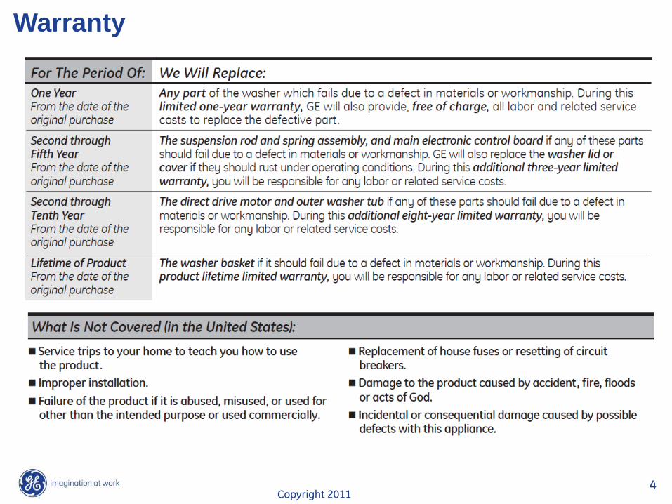
Warranty
Copyright 2011 5
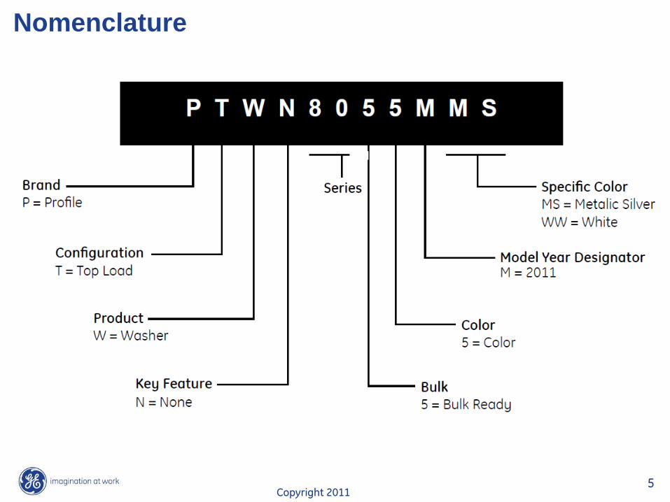
Nomenclature
Copyright 2011 6
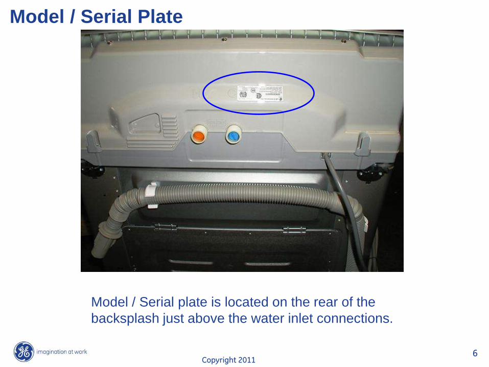
Model / Serial Plate
Model / Serial plate is located on the rear of the
backsplash just above the water inlet connections.
Copyright 2011 7
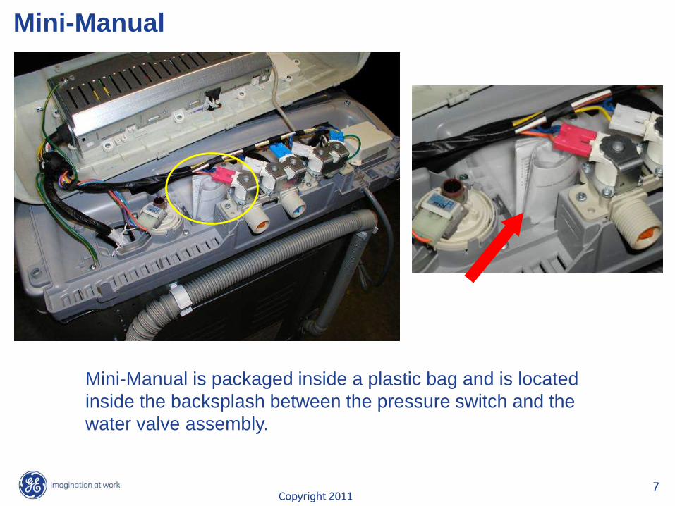
Mini-Manual
Mini-Manual is packaged inside a plastic bag and is located
inside the backsplash between the pressure switch and the
water valve assembly.
Copyright 2011 8
Wash Cycles
“Tidal Wave” or “Alpha Wash” Basket spins at 230 RPM clockwise then counter-clockwise.
“Centrifusion Wash” Basket spins slowly clockwise then counter-clockwise.
“Infusor Wash”
Tub remains stationary. Infusor turn clockwise then counter-clockwise.
Copyright 2011 9
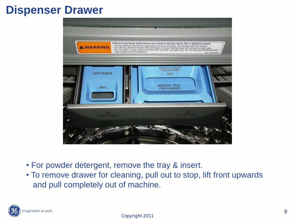
Dispenser Drawer
• For powder detergent, remove the tray & insert.
• To remove drawer for cleaning, pull out to stop, lift front upwards
and pull completely out of machine.
Copyright 2011 10
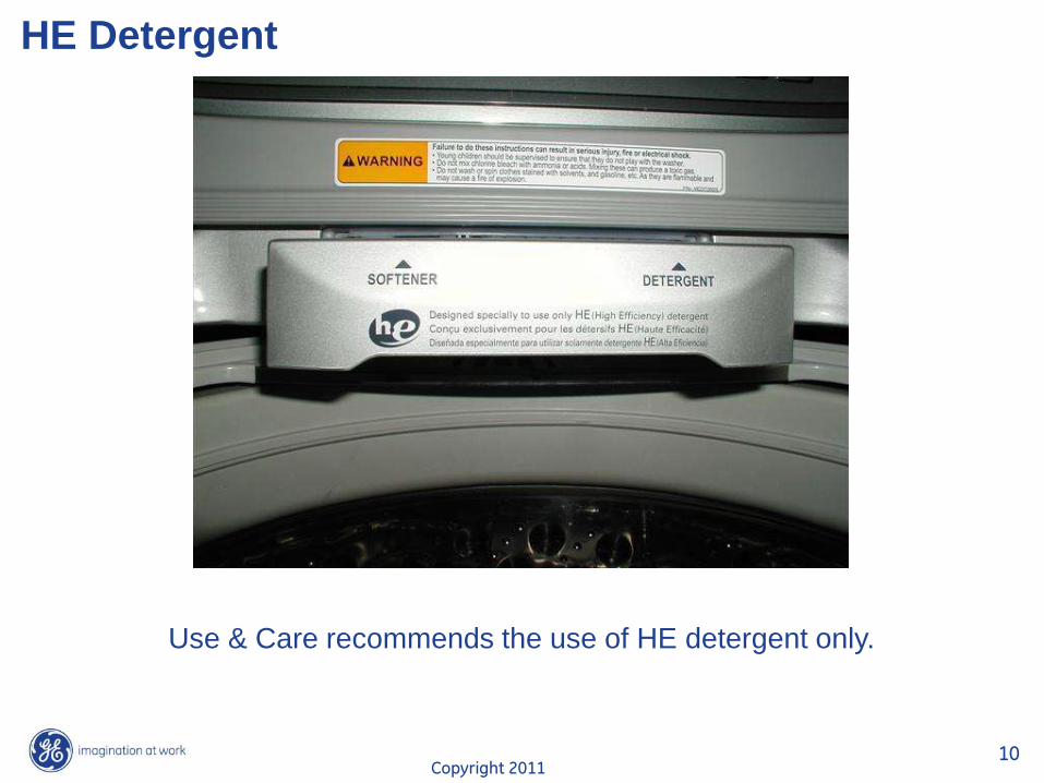
HE Detergent
Use & Care recommends the use of HE detergent only.
Copyright 2011 11
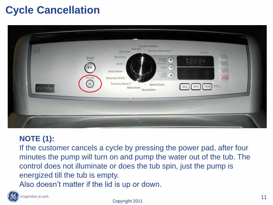
Cycle Cancellation
NOTE (1):
If the customer cancels a cycle by pressing the power pad, after four
minutes the pump will turn on and pump the water out of the tub. The
control does not illuminate or does the tub spin, just the pump is
energized till the tub is empty.
Also doesn’t matter if the lid is up or down.
Copyright 2011 12
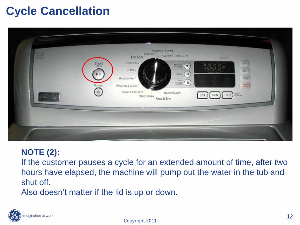
Cycle Cancellation
NOTE (2):
If the customer pauses a cycle for an extended amount of time, after two
hours have elapsed, the machine will pump out the water in the tub and
shut off.
Also doesn’t matter if the lid is up or down.
Copyright 2011 13
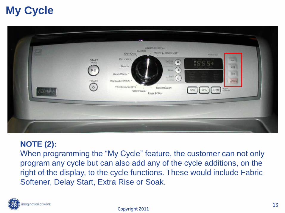
My Cycle
NOTE (2):
When programming the “My Cycle” feature, the customer can not only
program any cycle but can also add any of the cycle additions, on the
right of the display, to the cycle functions. These would include Fabric
Softener, Delay Start, Extra Rise or Soak.
Copyright 2011 14
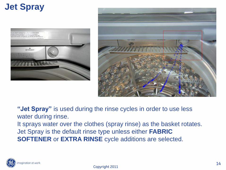
Jet Spray
“Jet Spray” is used during the rinse cycles in order to use less
water during rinse.
It sprays water over the clothes (spray rinse) as the basket rotates.
Jet Spray is the default rinse type unless either FABRIC
SOFTENER or EXTRA RINSE cycle additions are selected.
Copyright 2011 15
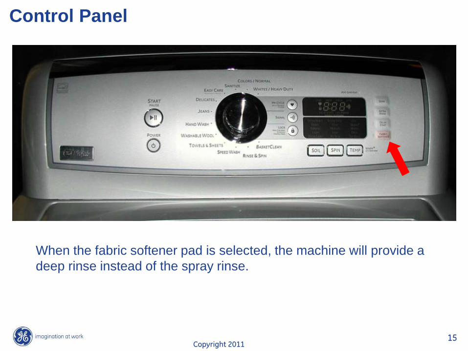
Control Panel
When the fabric softener pad is selected, the machine will provide a
deep rinse instead of the spray rinse.
Copyright 2011 16
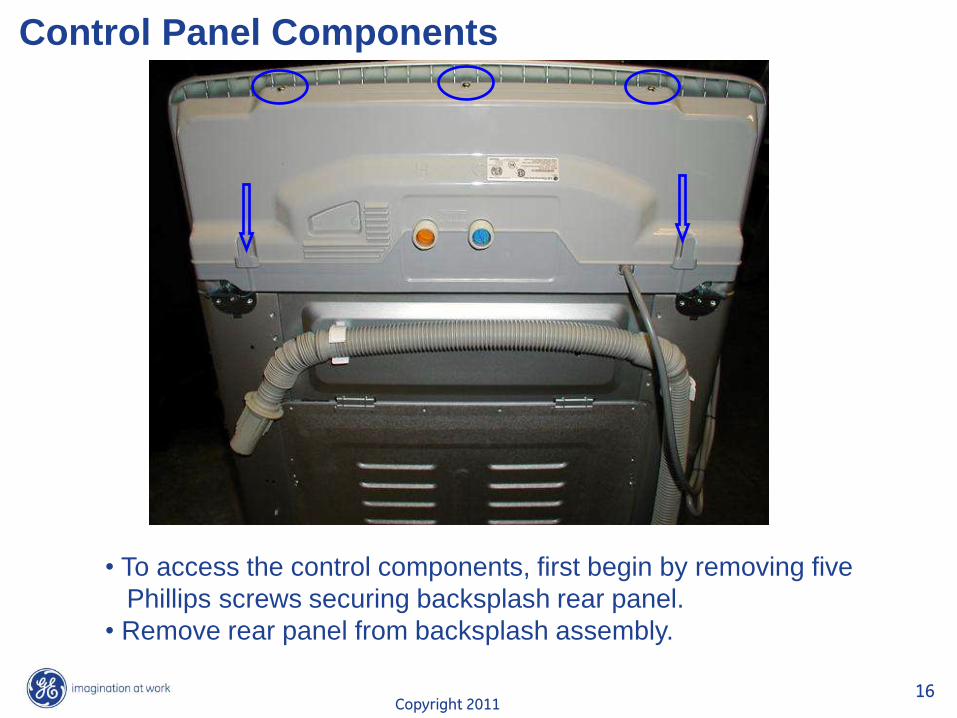
Control Panel Components
• To access the control components, first begin by removing five
Phillips screws securing backsplash rear panel.
• Remove rear panel from backsplash assembly.
Copyright 2011 17
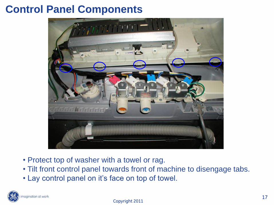
Control Panel Components
• Protect top of washer with a towel or rag.
• Tilt front control panel towards front of machine to disengage tabs.
• Lay control panel on it’s face on top of towel.
Copyright 2011 18
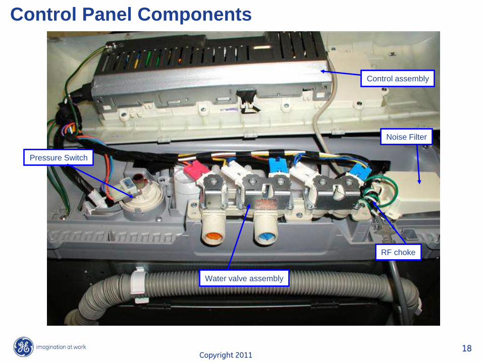
Control Panel Components
Pressure Switch
Water valve assembly
Noise Filter
RF choke
Control assembly
Copyright 2011 19
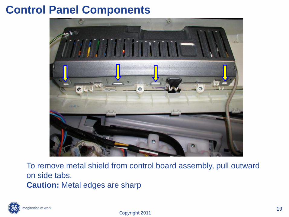
Control Panel Components
To remove metal shield from control board assembly, pull outward
on side tabs.
Caution: Metal edges are sharp
Copyright 2011 20
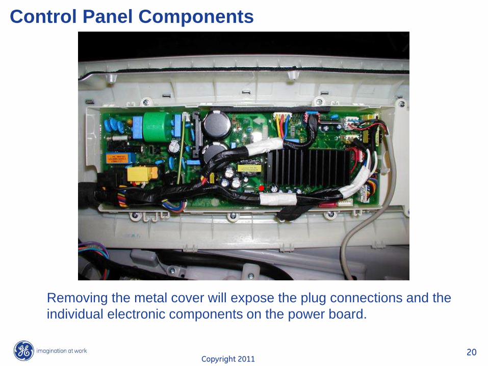
Control Panel Components
Removing the metal cover will expose the plug connections and the
individual electronic components on the power board.
Copyright 2011 21
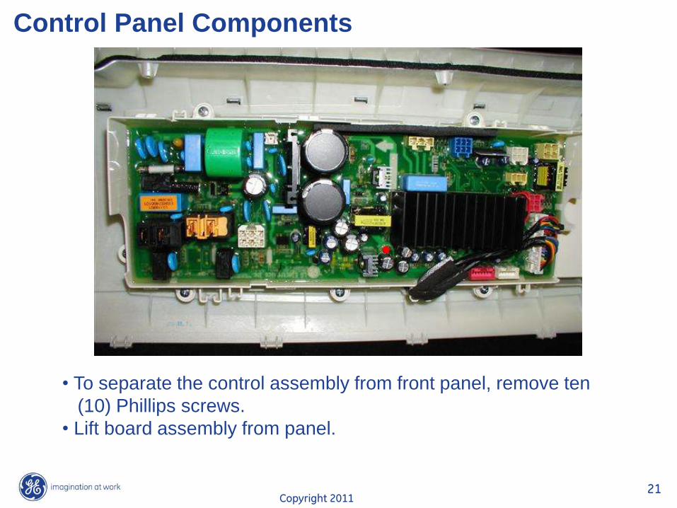
Control Panel Components
• To separate the control assembly from front panel, remove ten
(10) Phillips screws.
• Lift board assembly from panel.
Copyright 2011 22
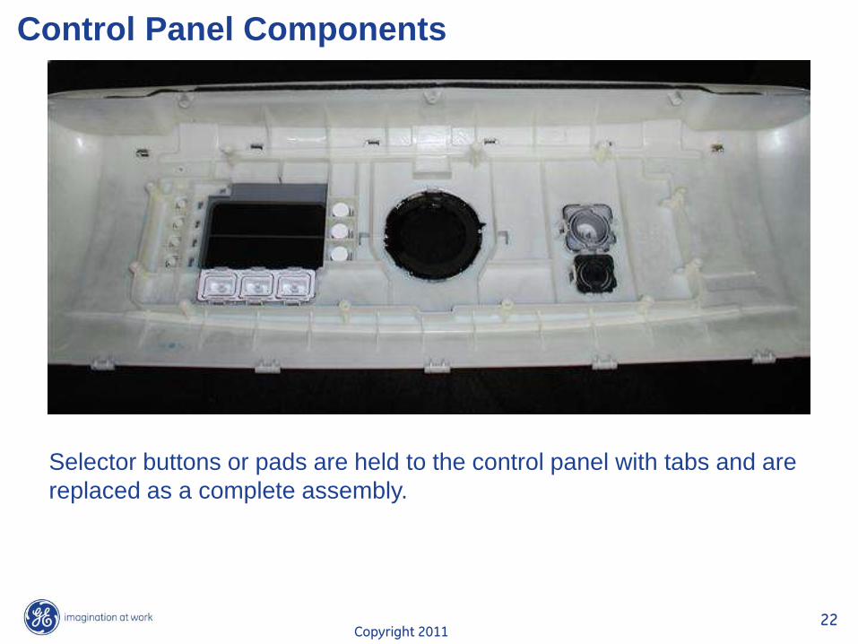
Control Panel Components
Selector buttons or pads are held to the control panel with tabs and are
replaced as a complete assembly.
Copyright 2011 23
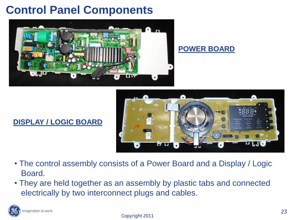
Control Panel Components
• The control assembly consists of a Power Board and a Display / Logic
Board.
• They are held together as an assembly by plastic tabs and connected
electrically by two interconnect plugs and cables.
POWER BOARD
DISPLAY / LOGIC BOARD
Copyright 2011 24
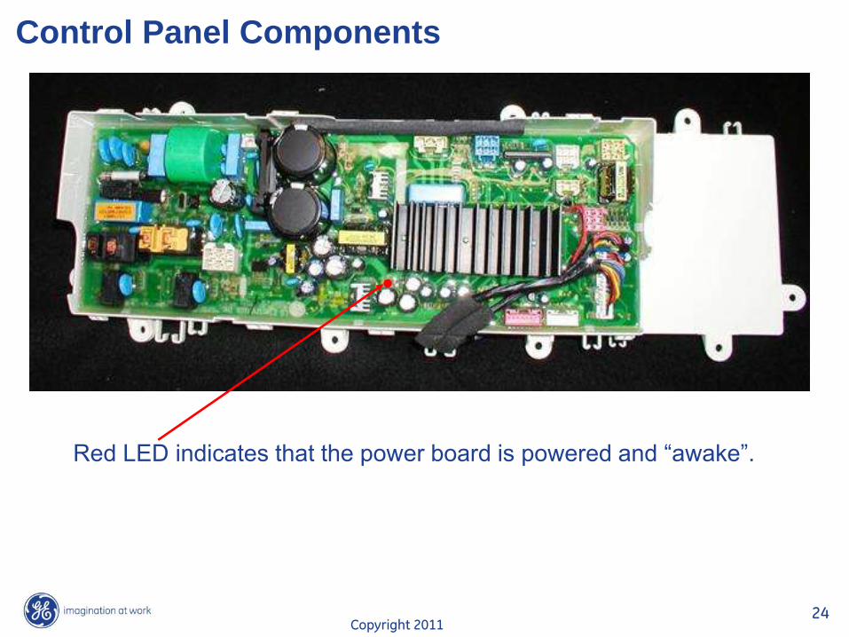
Control Panel Components
Red LED indicates that the power board is powered and “awake”.
Copyright 2011 25
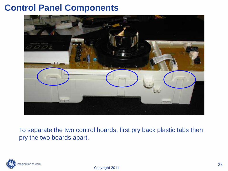
Control Panel Components
To separate the two control boards, first pry back plastic tabs then
pry the two boards apart.
Copyright 2011 26
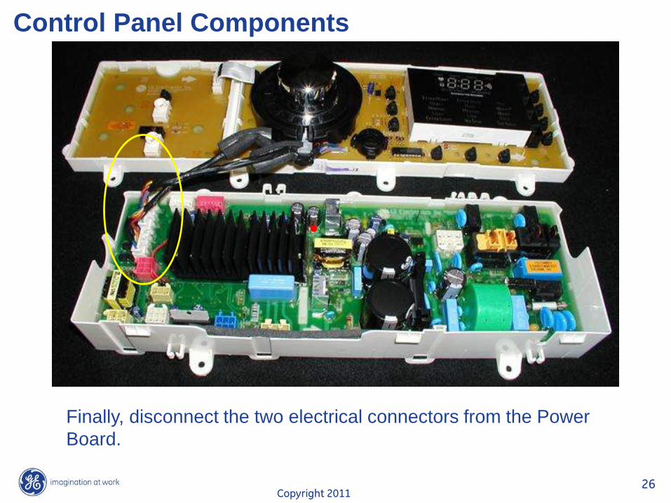
Control Panel Components
Finally, disconnect the two electrical connectors from the Power
Board.
Copyright 2011 27
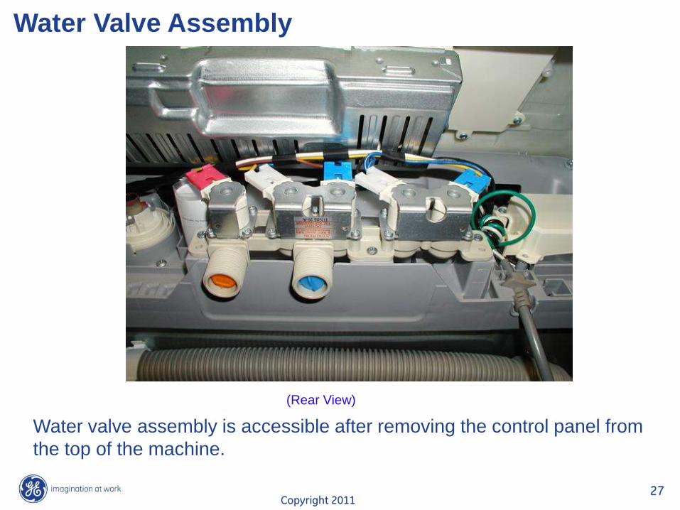
Water Valve Assembly
(Rear View)
Water valve assembly is accessible after removing the control panel from
the top of the machine.
Copyright 2011 28
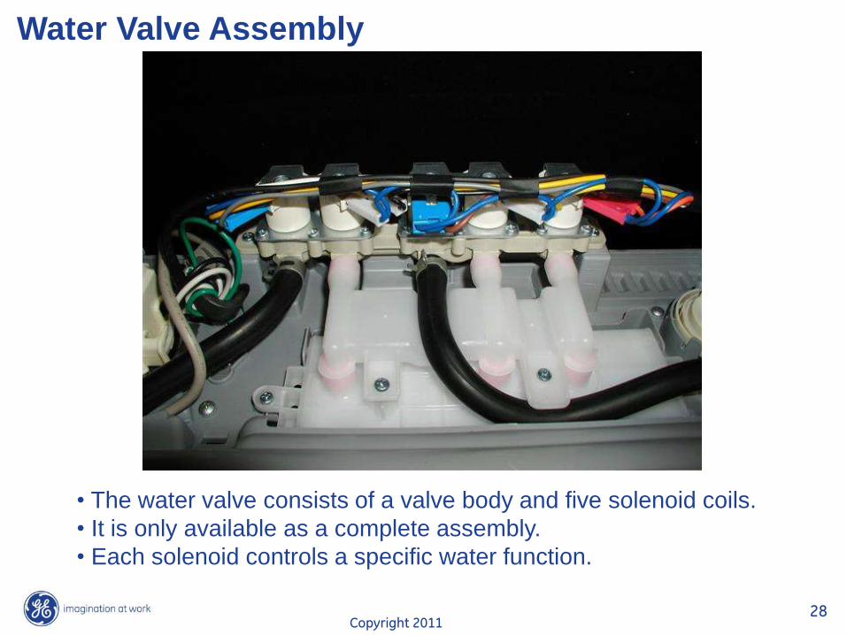
Water Valve Assembly
• The water valve consists of a valve body and five solenoid coils.
• It is only available as a complete assembly.
• Each solenoid controls a specific water function.
Copyright 2011 29
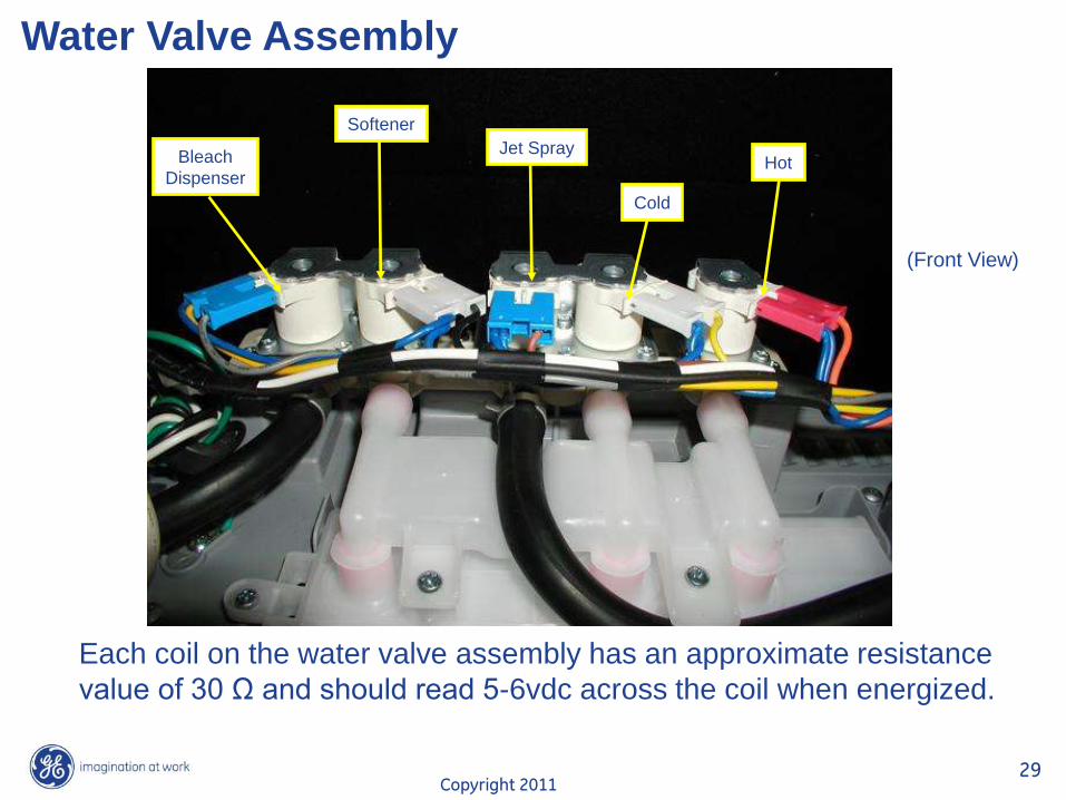
Water Valve Assembly
(Front View)
Bleach
Dispenser
Softener
Jet Spray
Cold
Hot
Each coil on the water valve assembly has an approximate resistance
value of 30 Ω and should read 5-6vdc across the coil when energized.
Copyright 2011 30
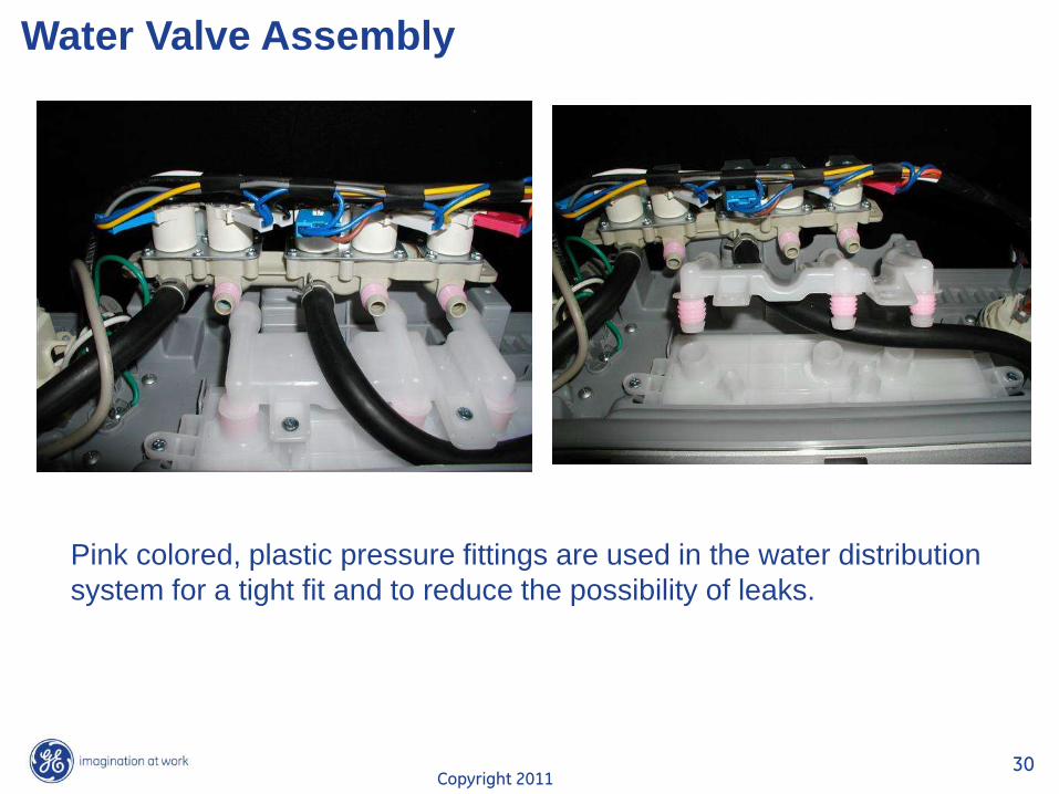
Water Valve Assembly
Pink colored, plastic pressure fittings are used in the water distribution
system for a tight fit and to reduce the possibility of leaks.
Copyright 2011 31
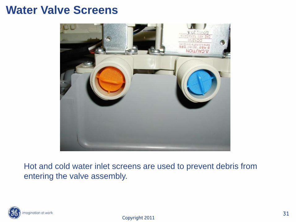
Water Valve Screens
Hot and cold water inlet screens are used to prevent debris from
entering the valve assembly.
Copyright 2011 32
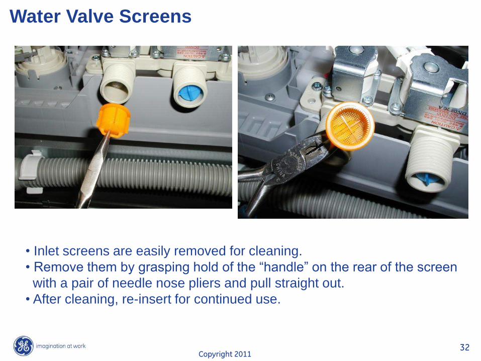
Water Valve Screens
• Inlet screens are easily removed for cleaning.
• Remove them by grasping hold of the “handle” on the rear of the screen
with a pair of needle nose pliers and pull straight out.
• After cleaning, re-insert for continued use.
Copyright 2011 33
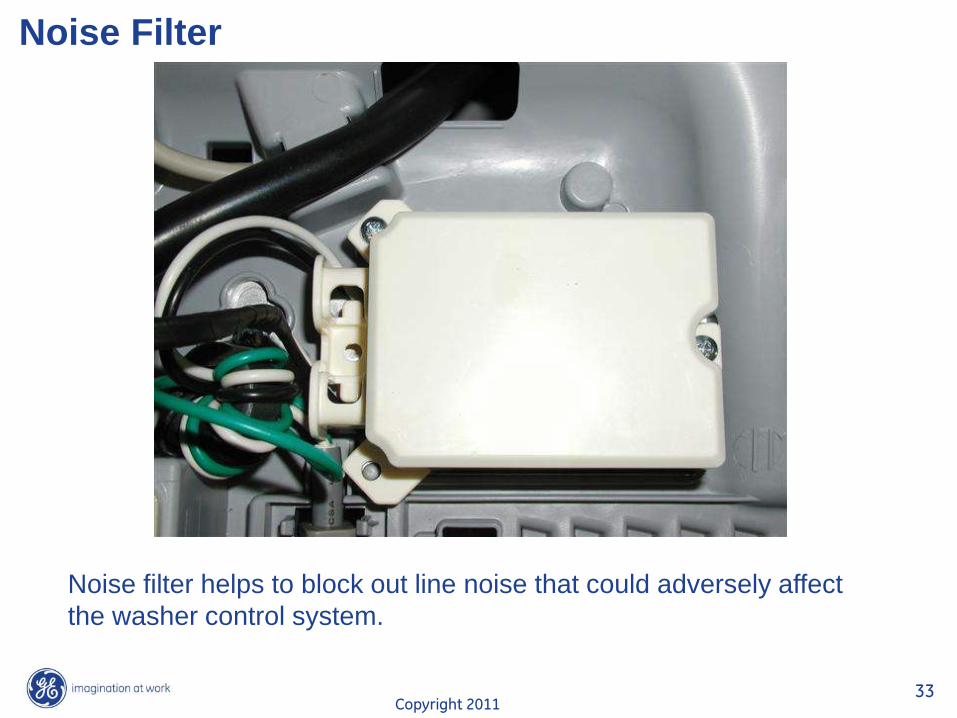
Noise Filter
Noise filter helps to block out line noise that could adversely affect
the washer control system.
Copyright 2011 34
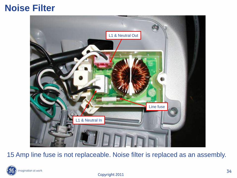
Noise Filter
L1 & Neutral Out
L1 & Neutral In
Line fuse
15 Amp line fuse is not replaceable. Noise filter is replaced as an assembly.
Copyright 2011 35
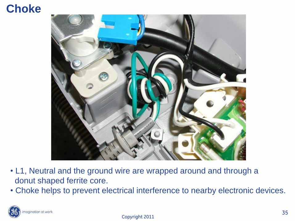
Choke
• L1, Neutral and the ground wire are wrapped around and through a
donut shaped ferrite core.
• Choke helps to prevent electrical interference to nearby electronic devices.
Copyright 2011 36
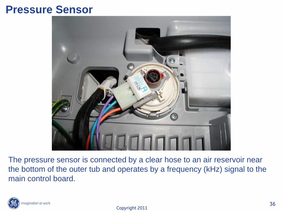
Pressure Sensor
The pressure sensor is connected by a clear hose to an air reservoir near
the bottom of the outer tub and operates by a frequency (kHz) signal to the
main control board.
Copyright 2011 37
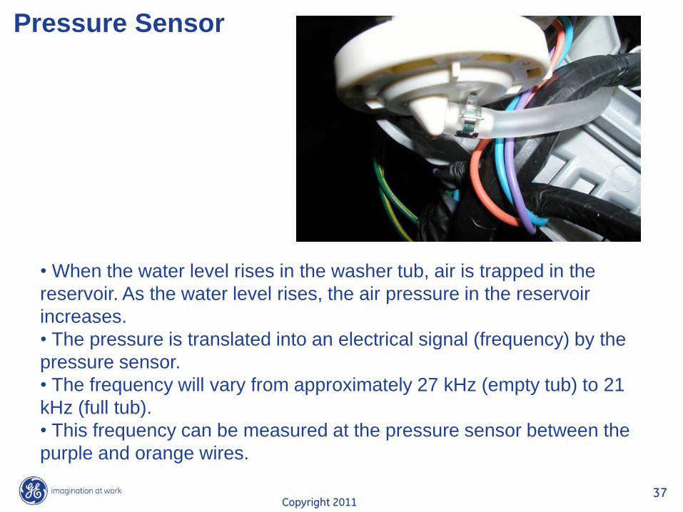
Pressure Sensor
• When the water level rises in the washer tub, air is trapped in the
reservoir. As the water level rises, the air pressure in the reservoir
increases.
• The pressure is translated into an electrical signal (frequency) by the
pressure sensor.
• The frequency will vary from approximately 27 kHz (empty tub) to 21
kHz (full tub).
• This frequency can be measured at the pressure sensor between the
purple and orange wires.
Copyright 2011 38
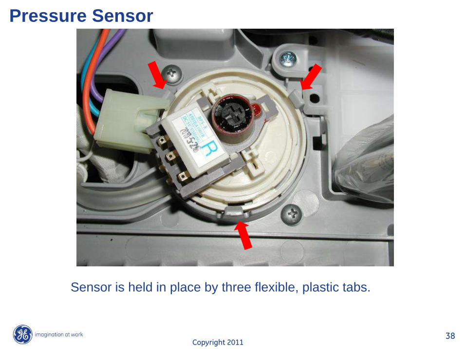
Pressure Sensor
Sensor is held in place by three flexible, plastic tabs.
Copyright 2011 39
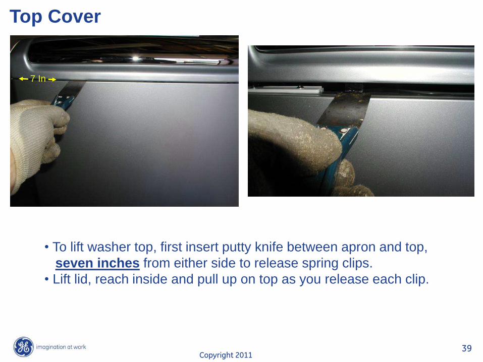
Top Cover
• To lift washer top, first insert putty knife between apron and top,
seven inches from either side to release spring clips.
• Lift lid, reach inside and pull up on top as you release each clip.
7 In
Copyright 2011 40
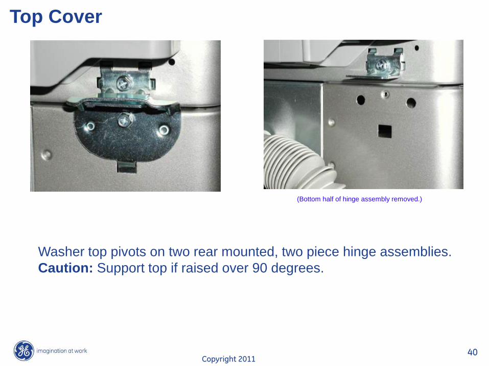
Top Cover
(Bottom half of hinge assembly removed.)
Washer top pivots on two rear mounted, two piece hinge assemblies.
Caution: Support top if raised over 90 degrees.
Copyright 2011 41
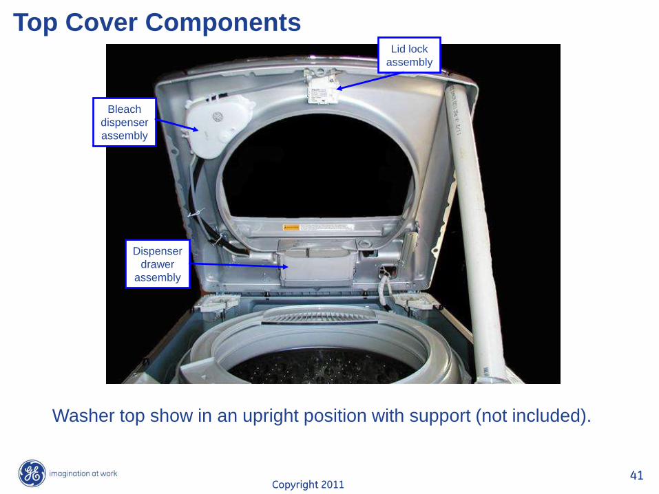
Top Cover Components
Bleach
dispenser
assembly
Lid lock
assembly
Dispenser
drawer
assembly
Washer top show in an upright position with support (not included).
Copyright 2011 42
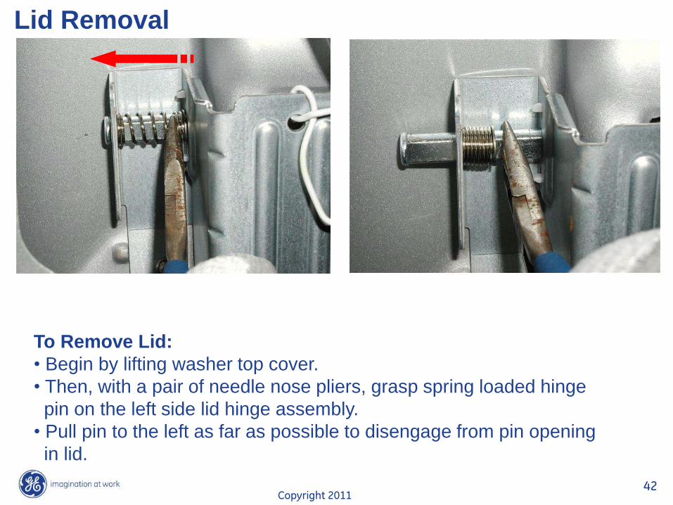
Lid Removal
To Remove Lid:
• Begin by lifting washer top cover.
• Then, with a pair of needle nose pliers, grasp spring loaded hinge
pin on the left side lid hinge assembly.
• Pull pin to the left as far as possible to disengage from pin opening
in lid.
Copyright 2011 43
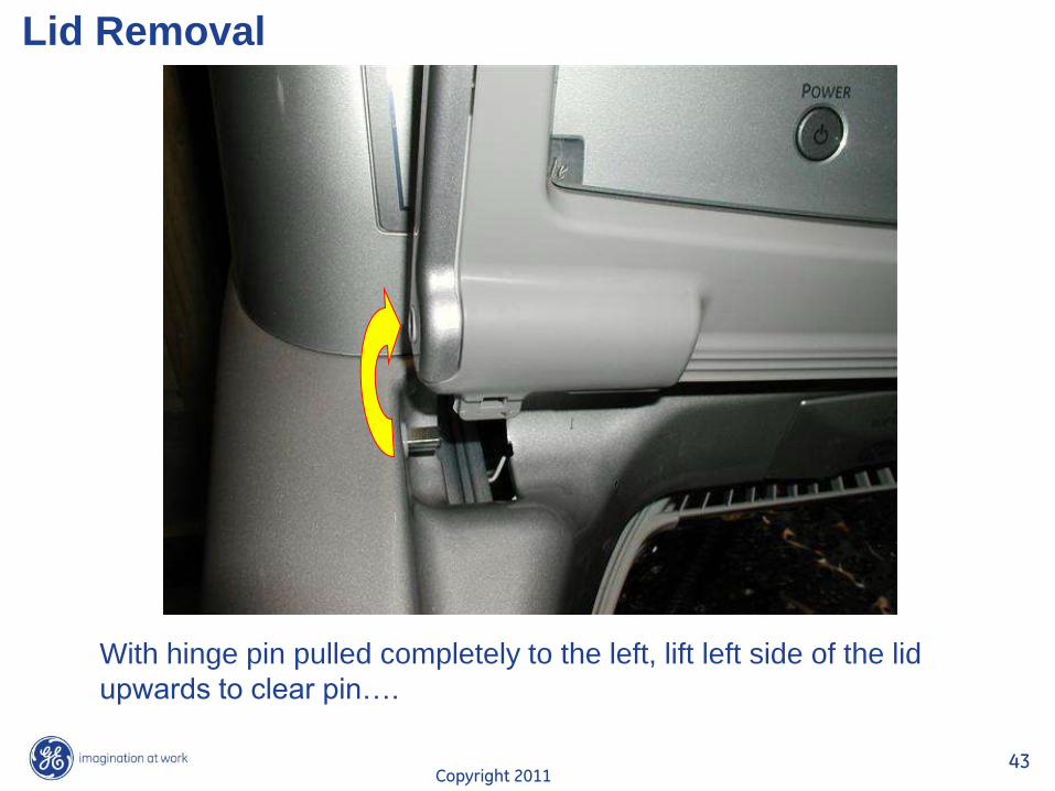
Lid Removal
With hinge pin pulled completely to the left, lift left side of the lid
upwards to clear pin….
Copyright 2011 44
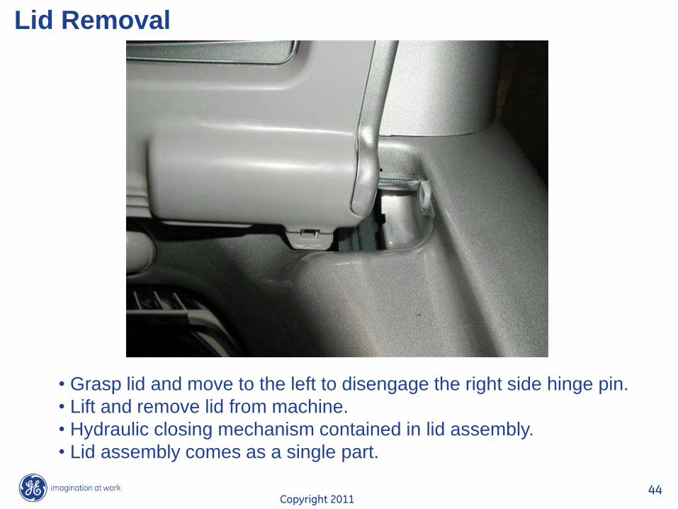
Lid Removal
• Grasp lid and move to the left to disengage the right side hinge pin.
• Lift and remove lid from machine.
• Hydraulic closing mechanism contained in lid assembly.
• Lid assembly comes as a single part.
Copyright 2011 45
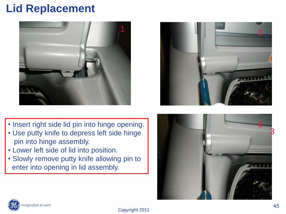
Lid Replacement
• Insert right side lid pin into hinge opening.
• Use putty knife to depress left side hinge
pin into hinge assembly.
• Lower left side of lid into position.
• Slowly remove putty knife allowing pin to
enter into opening in lid assembly.
1 2 2
3 3
Copyright 2011 46
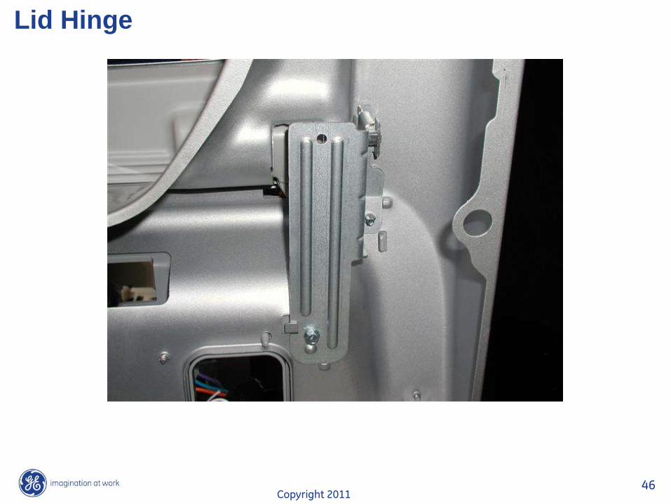
Lid Hinge
Copyright 2011 47
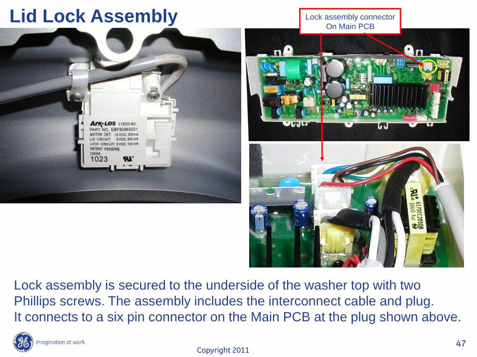
Lid Lock Assembly Lock assembly connector
On Main PCB
Lock assembly is secured to the underside of the washer top with two
Phillips screws. The assembly includes the interconnect cable and plug.
It connects to a six pin connector on the Main PCB at the plug shown above.
Copyright 2011 48
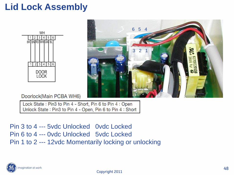
Lid Lock Assembly
3 2 1
6 5 4
Pin 3 to 4 --- 5vdc Unlocked 0vdc Locked
Pin 6 to 4 --- 0vdc Unlocked 5vdc Locked
Pin 1 to 2 --- 12vdc Momentarily locking or unlocking
Copyright 2011 49
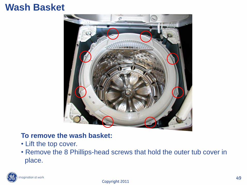
Wash Basket
To remove the wash basket:
• Lift the top cover.
• Remove the 8 Phillips-head screws that hold the outer tub cover in
place.
Copyright 2011 50
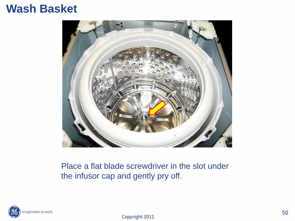
Wash Basket
Place a flat blade screwdriver in the slot under
the infusor cap and gently pry off.
Copyright 2011 51
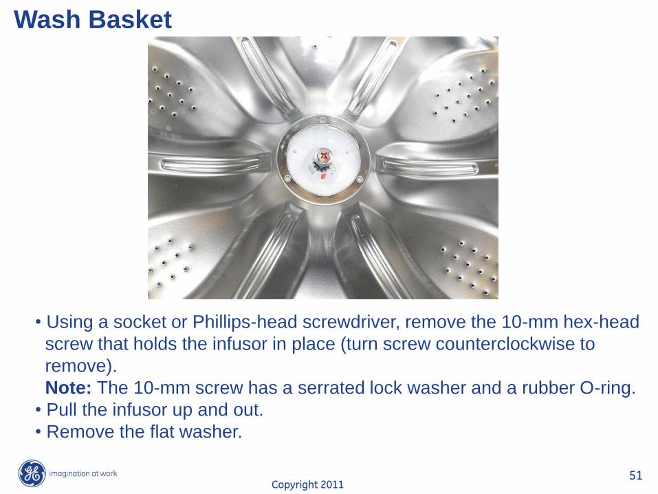
Wash Basket
• Using a socket or Phillips-head screwdriver, remove the 10-mm hex-head
screw that holds the infusor in place (turn screw counterclockwise to
remove).
Note: The 10-mm screw has a serrated lock washer and a rubber O-ring.
• Pull the infusor up and out.
• Remove the flat washer.
Copyright 2011 52
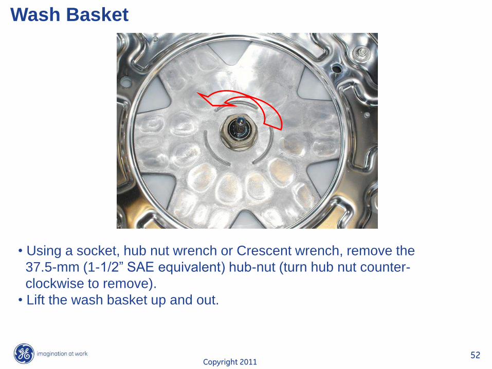
Wash Basket
• Using a socket, hub nut wrench or Crescent wrench, remove the
37.5-mm (1-1/2” SAE equivalent) hub-nut (turn hub nut counter-
clockwise to remove).
• Lift the wash basket up and out.
Copyright 2011 53
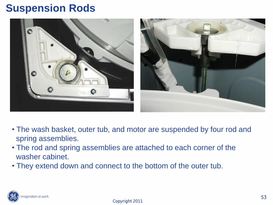
Suspension Rods
• The wash basket, outer tub, and motor are suspended by four rod and
spring assemblies.
• The rod and spring assemblies are attached to each corner of the
washer cabinet.
• They extend down and connect to the bottom of the outer tub.
Copyright 2011 54
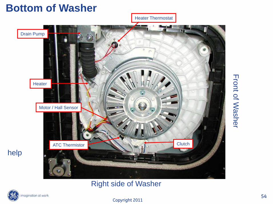
Bottom of Washer Heater Thermostat
Heater
Drain Pump
Clutch
Motor / Hall Sensor
ATC Thermistor
help
Fro
nt o
f Wa
sh
er
Right side of Washer
Copyright 2011 55
Heater
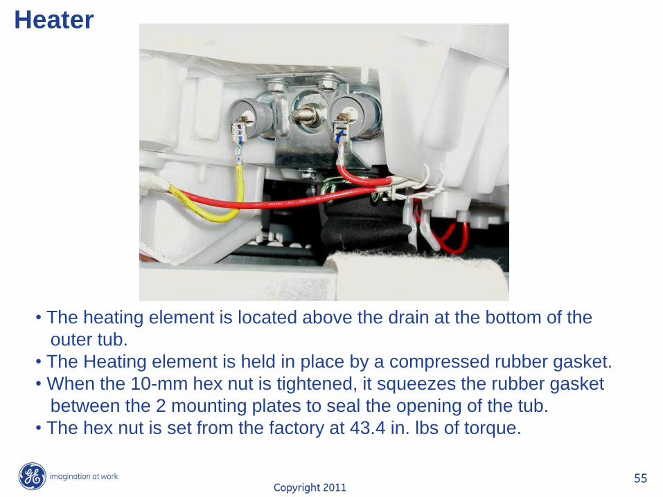
• The heating element is located above the drain at the bottom of the
outer tub.
• The Heating element is held in place by a compressed rubber gasket.
• When the 10-mm hex nut is tightened, it squeezes the rubber gasket
between the 2 mounting plates to seal the opening of the tub.
• The hex nut is set from the factory at 43.4 in. lbs of torque.
Copyright 2011 56
Heater
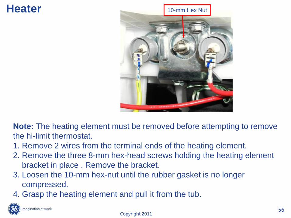
Note: The heating element must be removed before attempting to remove
the hi-limit thermostat.
1. Remove 2 wires from the terminal ends of the heating element.
2. Remove the three 8-mm hex-head screws holding the heating element
bracket in place . Remove the bracket.
3. Loosen the 10-mm hex-nut until the rubber gasket is no longer
compressed.
4. Grasp the heating element and pull it from the tub.
10-mm Hex Nut
Copyright 2011 57
Heater
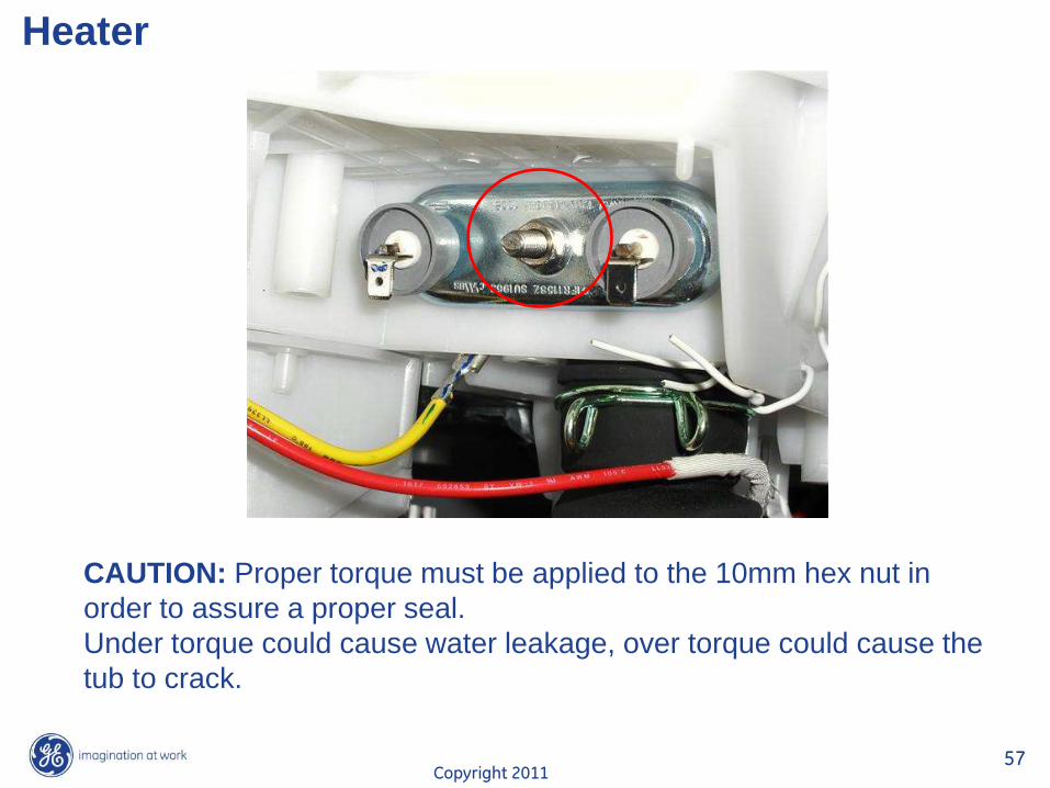
CAUTION: Proper torque must be applied to the 10mm hex nut in
order to assure a proper seal.
Under torque could cause water leakage, over torque could cause the
tub to crack.
Copyright 2011 58
Heater
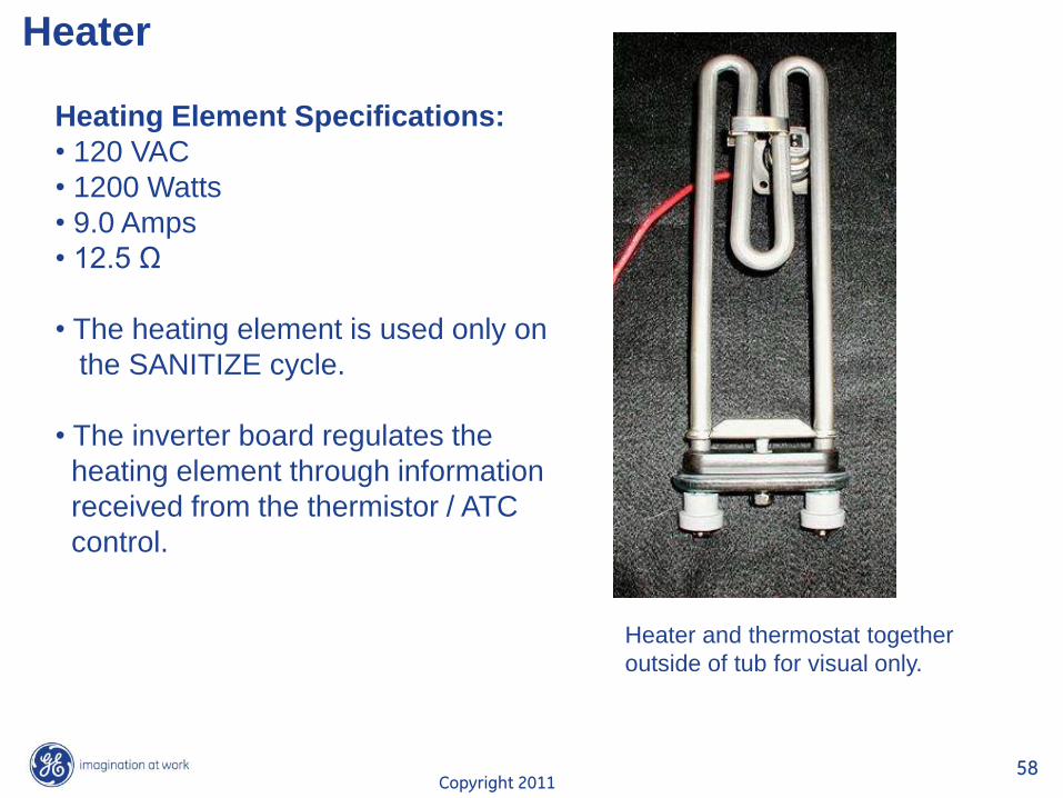
Heater and thermostat together
outside of tub for visual only.
Heating Element Specifications:
• 120 VAC
• 1200 Watts
• 9.0 Amps
• 12.5 Ω
• The heating element is used only on
the SANITIZE cycle.
• The inverter board regulates the
heating element through information
received from the thermistor / ATC
control.
Copyright 2011 59
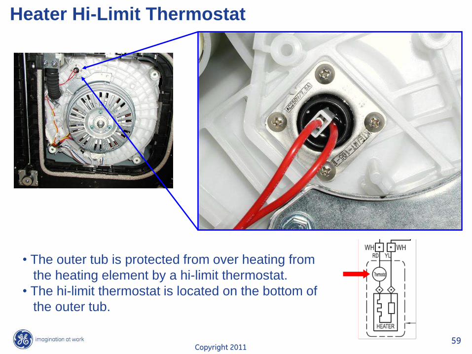
Heater Hi-Limit Thermostat
• The outer tub is protected from over heating from
the heating element by a hi-limit thermostat.
• The hi-limit thermostat is located on the bottom of
the outer tub.
Copyright 2011 60
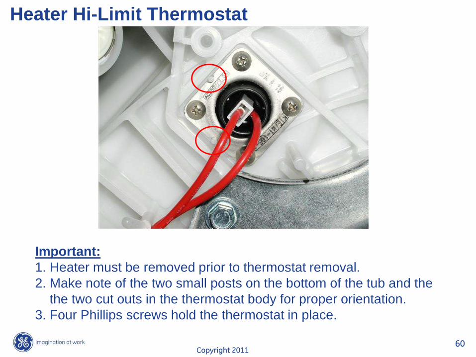
Heater Hi-Limit Thermostat
Important:
1. Heater must be removed prior to thermostat removal.
2. Make note of the two small posts on the bottom of the tub and the
the two cut outs in the thermostat body for proper orientation.
3. Four Phillips screws hold the thermostat in place.
Copyright 2011 61
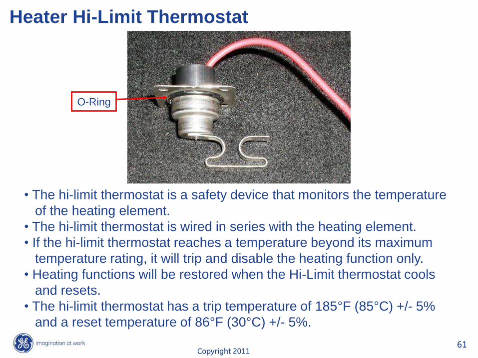
Heater Hi-Limit Thermostat
O-Ring
• The hi-limit thermostat is a safety device that monitors the temperature
of the heating element.
• The hi-limit thermostat is wired in series with the heating element.
• If the hi-limit thermostat reaches a temperature beyond its maximum
temperature rating, it will trip and disable the heating function only.
• Heating functions will be restored when the Hi-Limit thermostat cools
and resets.
• The hi-limit thermostat has a trip temperature of 185°F (85°C) +/- 5%
and a reset temperature of 86°F (30°C) +/- 5%.
Copyright 2011 62
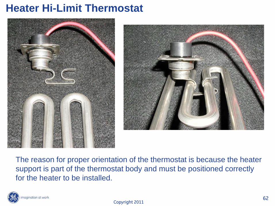
Heater Hi-Limit Thermostat
The reason for proper orientation of the thermostat is because the heater
support is part of the thermostat body and must be positioned correctly
for the heater to be installed.
Copyright 2011 63
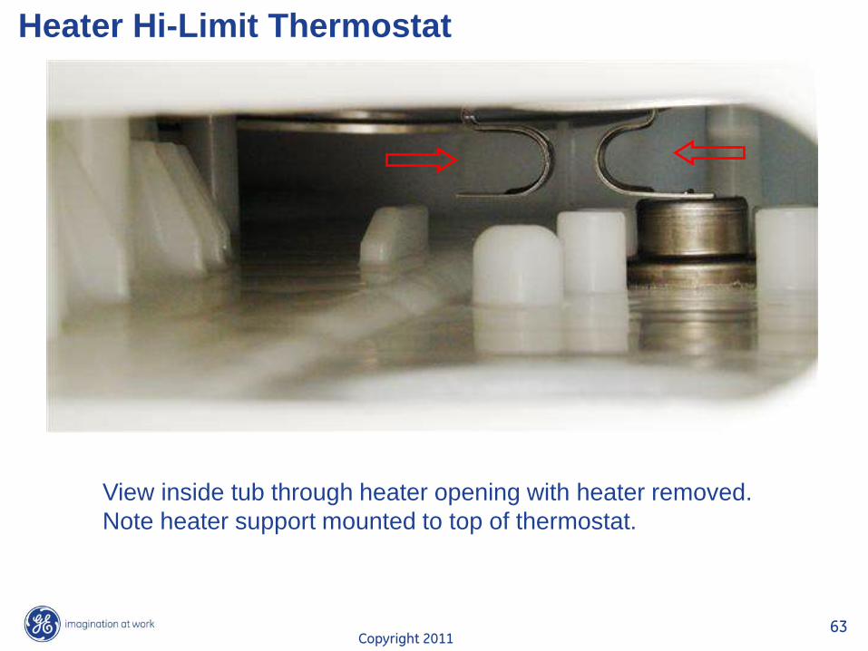
Heater Hi-Limit Thermostat
View inside tub through heater opening with heater removed.
Note heater support mounted to top of thermostat.
Copyright 2011 64
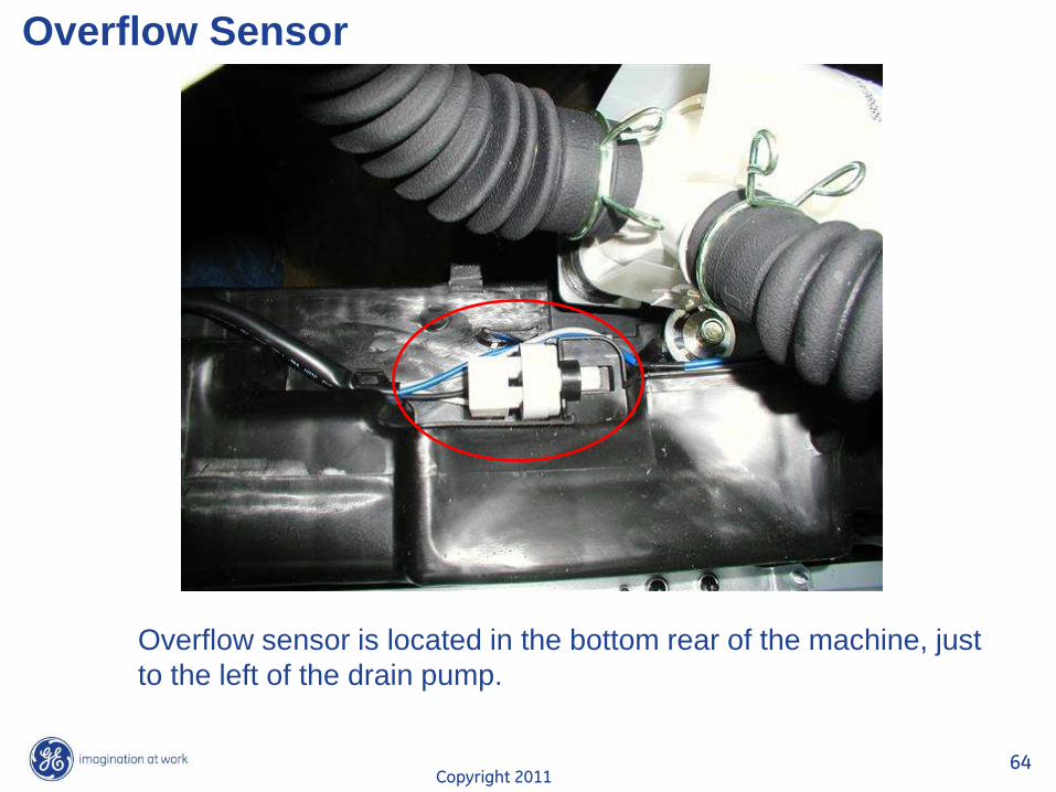
Overflow Sensor
Overflow sensor is located in the bottom rear of the machine, just
to the left of the drain pump.
Copyright 2011 65
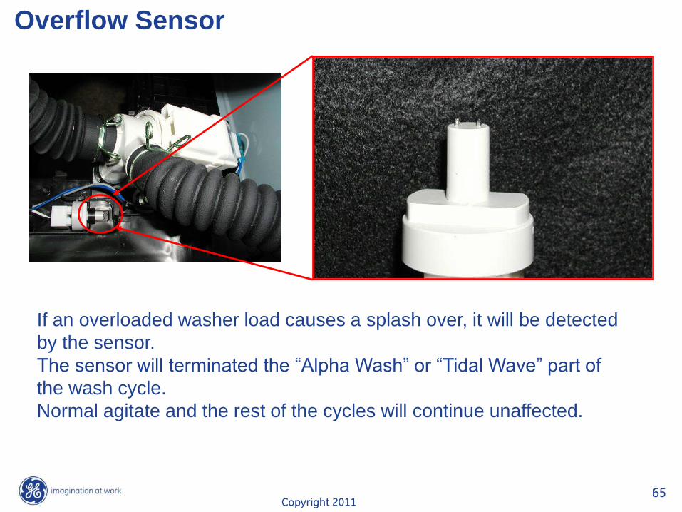
Overflow Sensor
If an overloaded washer load causes a splash over, it will be detected
by the sensor.
The sensor will terminated the “Alpha Wash” or “Tidal Wave” part of
the wash cycle.
Normal agitate and the rest of the cycles will continue unaffected.
Copyright 2011 66
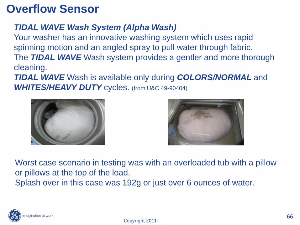
Overflow Sensor
TIDAL WAVE Wash System (Alpha Wash)
Your washer has an innovative washing system which uses rapid
spinning motion and an angled spray to pull water through fabric.
The TIDAL WAVE Wash system provides a gentler and more thorough
cleaning.
TIDAL WAVE Wash is available only during COLORS/NORMAL and
WHITES/HEAVY DUTY cycles. (from U&C 49-90404)
Worst case scenario in testing was with an overloaded tub with a pillow
or pillows at the top of the load.
Splash over in this case was 192g or just over 6 ounces of water.
Copyright 2011 67
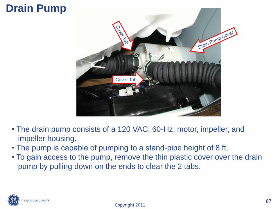
Drain Pump
• The drain pump consists of a 120 VAC, 60-Hz, motor, impeller, and
impeller housing.
• The pump is capable of pumping to a stand-pipe height of 8 ft.
• To gain access to the pump, remove the thin plastic cover over the drain
pump by pulling down on the ends to clear the 2 tabs.
Cover Tab
Copyright 2011 68
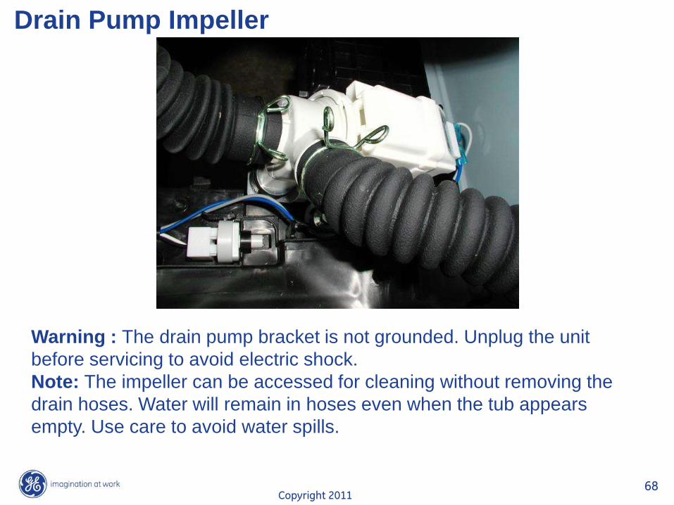
Drain Pump Impeller
Warning : The drain pump bracket is not grounded. Unplug the unit
before servicing to avoid electric shock.
Note: The impeller can be accessed for cleaning without removing the
drain hoses. Water will remain in hoses even when the tub appears
empty. Use care to avoid water spills.
Copyright 2011 69
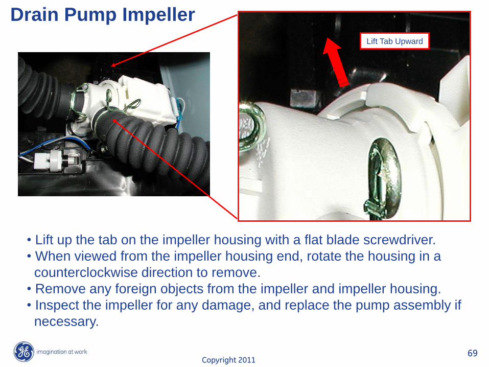
Drain Pump Impeller
• Lift up the tab on the impeller housing with a flat blade screwdriver.
• When viewed from the impeller housing end, rotate the housing in a
counterclockwise direction to remove.
• Remove any foreign objects from the impeller and impeller housing.
• Inspect the impeller for any damage, and replace the pump assembly if
necessary.
Lift Tab Upward
Copyright 2011 70
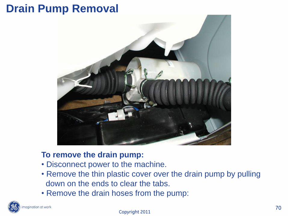
Drain Pump Removal
To remove the drain pump:
• Disconnect power to the machine.
• Remove the thin plastic cover over the drain pump by pulling
down on the ends to clear the tabs.
• Remove the drain hoses from the pump:
Copyright 2011 71
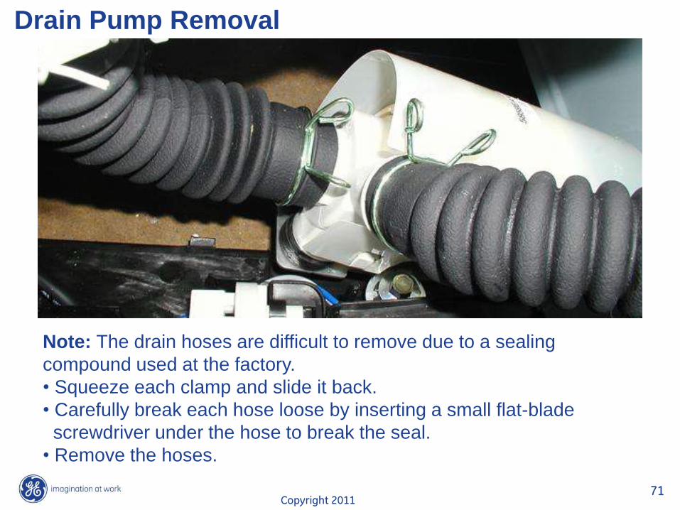
Drain Pump Removal
Note: The drain hoses are difficult to remove due to a sealing
compound used at the factory.
• Squeeze each clamp and slide it back.
• Carefully break each hose loose by inserting a small flat-blade
screwdriver under the hose to break the seal.
• Remove the hoses.
Copyright 2011 72
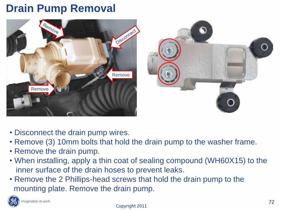
Drain Pump Removal
• Disconnect the drain pump wires.
• Remove (3) 10mm bolts that hold the drain pump to the washer frame.
• Remove the drain pump.
• When installing, apply a thin coat of sealing compound (WH60X15) to the
inner surface of the drain hoses to prevent leaks.
• Remove the 2 Phillips-head screws that hold the drain pump to the
mounting plate. Remove the drain pump.
Remove
Remove
Copyright 2011 73
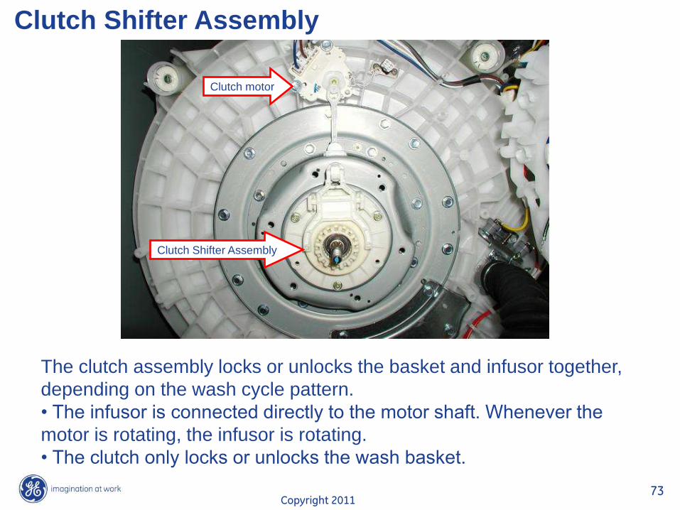
Clutch Shifter Assembly
The clutch assembly locks or unlocks the basket and infusor together,
depending on the wash cycle pattern.
• The infusor is connected directly to the motor shaft. Whenever the
motor is rotating, the infusor is rotating.
• The clutch only locks or unlocks the wash basket.
Clutch motor
Clutch Shifter Assembly
Copyright 2011 74
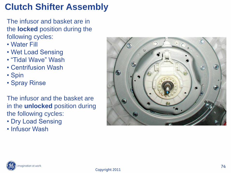
Clutch Shifter Assembly
The infusor and basket are in
the locked position during the
following cycles:
• Water Fill
• Wet Load Sensing
• “Tidal Wave” Wash
• Centrifusion Wash
• Spin
• Spray Rinse
The infusor and the basket are
in the unlocked position during
the following cycles:
• Dry Load Sensing
• Infusor Wash
Copyright 2011 75
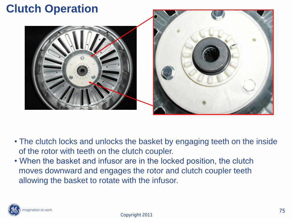
Clutch Operation
• The clutch locks and unlocks the basket by engaging teeth on the inside
of the rotor with teeth on the clutch coupler.
• When the basket and infusor are in the locked position, the clutch
moves downward and engages the rotor and clutch coupler teeth
allowing the basket to rotate with the infusor.
Copyright 2011 76
Clutch Operation
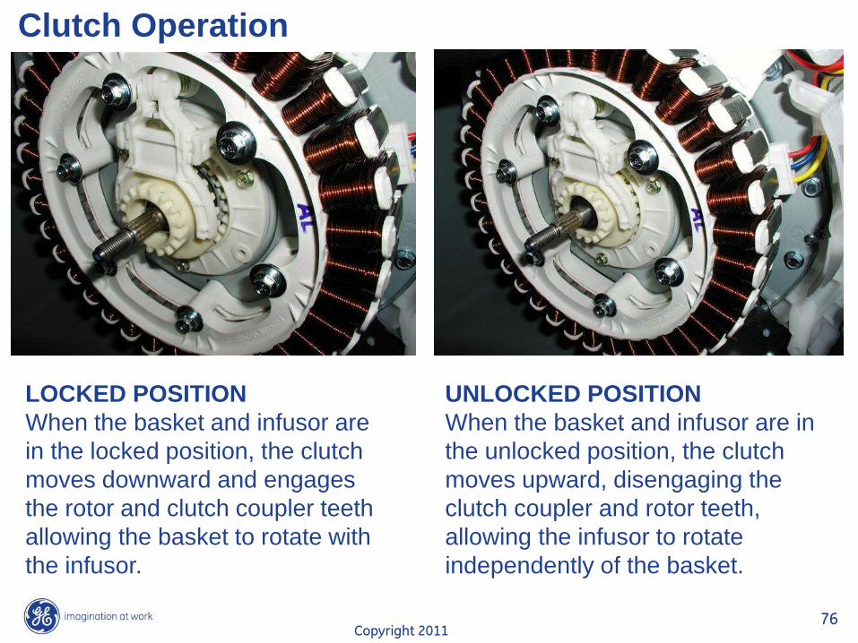
LOCKED POSITION
When the basket and infusor are
in the locked position, the clutch
moves downward and engages
the rotor and clutch coupler teeth
allowing the basket to rotate with
the infusor.
UNLOCKED POSITION
When the basket and infusor are in
the unlocked position, the clutch
moves upward, disengaging the
clutch coupler and rotor teeth,
allowing the infusor to rotate
independently of the basket.
Copyright 2011 77
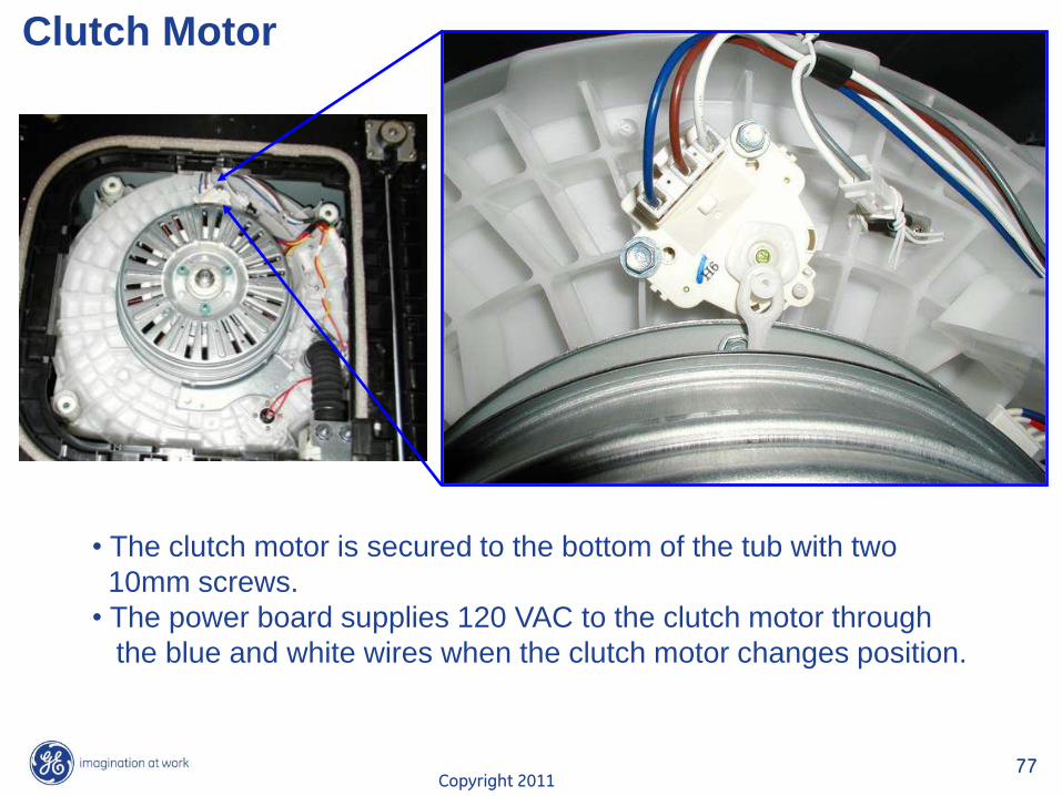
Clutch Motor
• The clutch motor is secured to the bottom of the tub with two
10mm screws.
• The power board supplies 120 VAC to the clutch motor through
the blue and white wires when the clutch motor changes position.
Copyright 2011 78
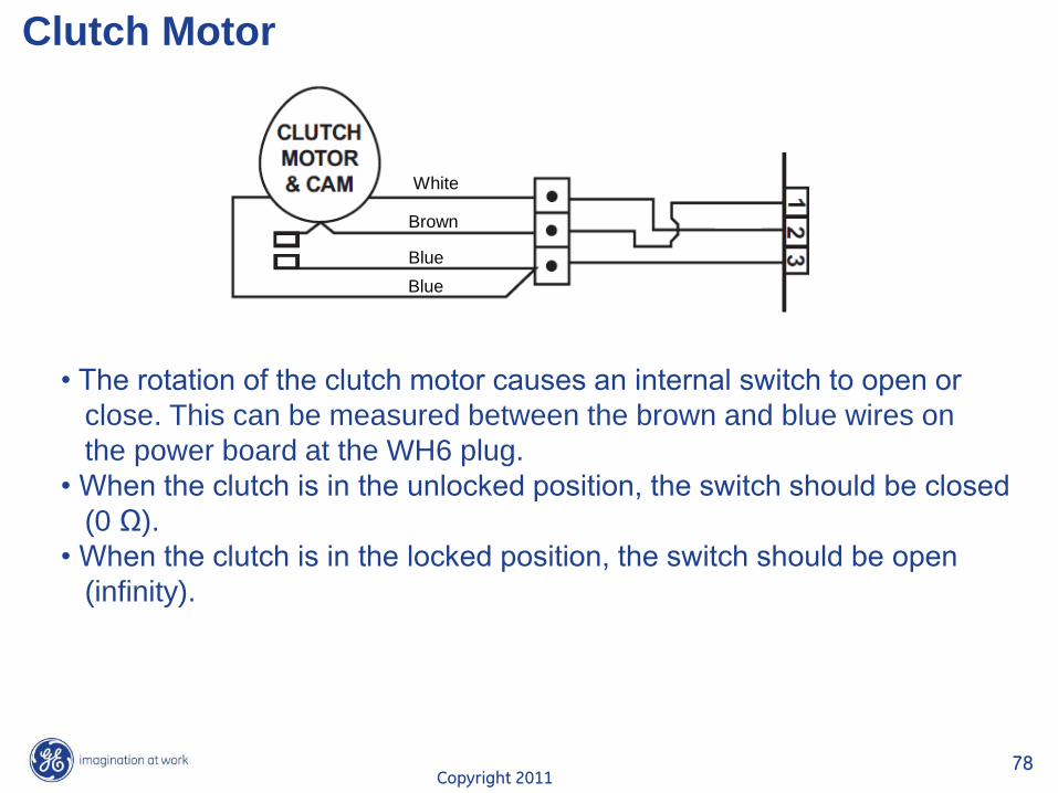
Clutch Motor
• The rotation of the clutch motor causes an internal switch to open or
close. This can be measured between the brown and blue wires on
the power board at the WH6 plug.
• When the clutch is in the unlocked position, the switch should be closed
(0 Ω).
• When the clutch is in the locked position, the switch should be open
(infinity).
White
Brown
Blue
Blue
Copyright 2011 79
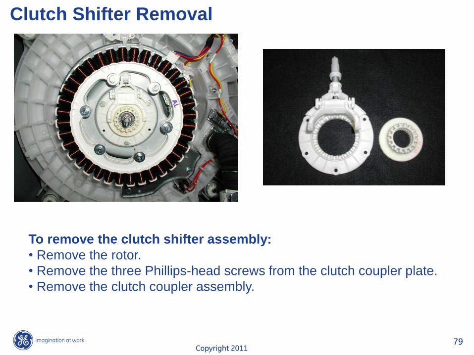
Clutch Shifter Removal
To remove the clutch shifter assembly:
• Remove the rotor.
• Remove the three Phillips-head screws from the clutch coupler plate.
• Remove the clutch coupler assembly.
Copyright 2011 80
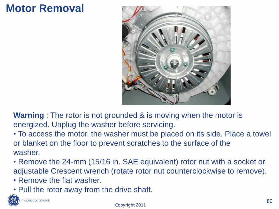
Motor Removal
Warning : The rotor is not grounded & is moving when the motor is
energized. Unplug the washer before servicing.
• To access the motor, the washer must be placed on its side. Place a towel
or blanket on the floor to prevent scratches to the surface of the
washer.
• Remove the 24-mm (15/16 in. SAE equivalent) rotor nut with a socket or
adjustable Crescent wrench (rotate rotor nut counterclockwise to remove).
• Remove the flat washer.
• Pull the rotor away from the drive shaft.
Copyright 2011 81
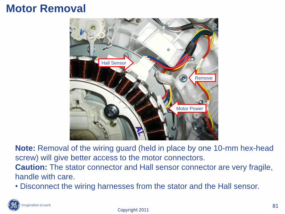
Motor Removal
Note: Removal of the wiring guard (held in place by one 10-mm hex-head
screw) will give better access to the motor connectors.
Caution: The stator connector and Hall sensor connector are very fragile,
handle with care.
• Disconnect the wiring harnesses from the stator and the Hall sensor.
Hall Sensor
Motor Power
Remove
Copyright 2011 82
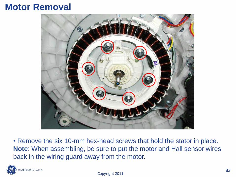
Motor Removal
• Remove the six 10-mm hex-head screws that hold the stator in place.
Note: When assembling, be sure to put the motor and Hall sensor wires
back in the wiring guard away from the motor.
Copyright 2011 83
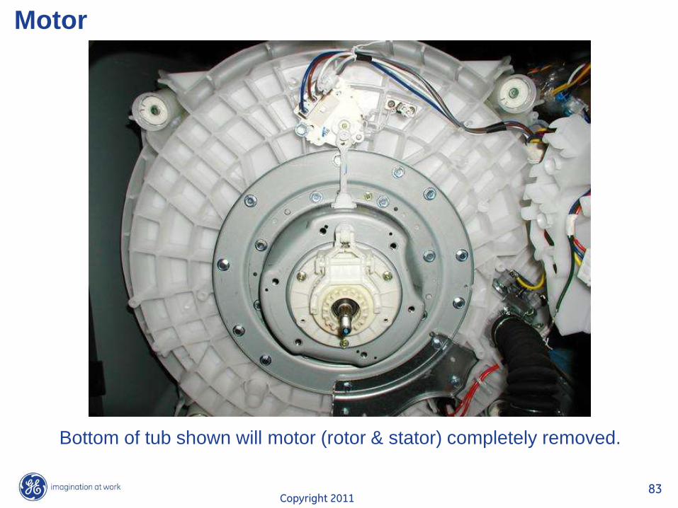
Motor
Bottom of tub shown will motor (rotor & stator) completely removed.
Copyright 2011 84
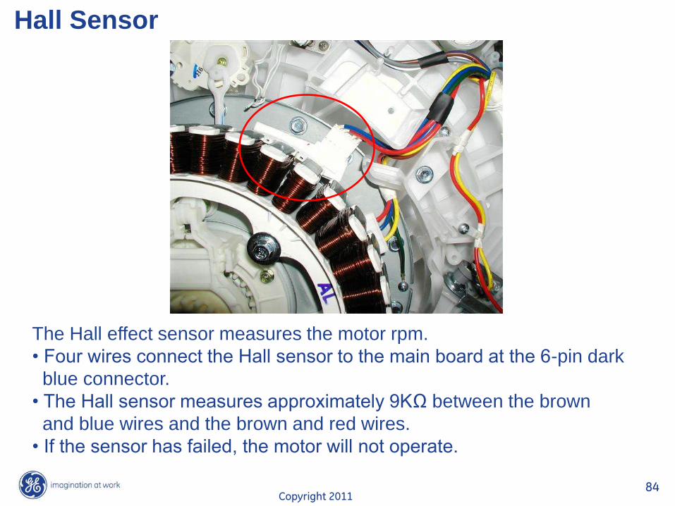
Hall Sensor
The Hall effect sensor measures the motor rpm.
• Four wires connect the Hall sensor to the main board at the 6-pin dark
blue connector.
• The Hall sensor measures approximately 9KΩ between the brown
and blue wires and the brown and red wires.
• If the sensor has failed, the motor will not operate.
Copyright 2011 85
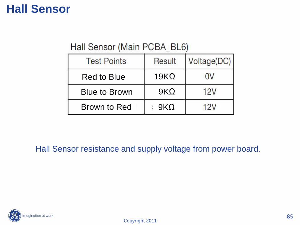
Hall Sensor
Hall Sensor resistance and supply voltage from power board.
Red to Blue
Blue to Brown
Brown to Red
19KΩ
9KΩ
9KΩ
Copyright 2011 86
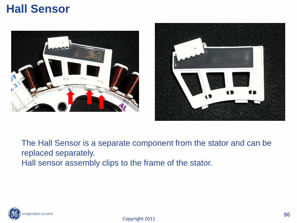
Hall Sensor
The Hall Sensor is a separate component from the stator and can be
replaced separately.
Hall sensor assembly clips to the frame of the stator.
Copyright 2011 87
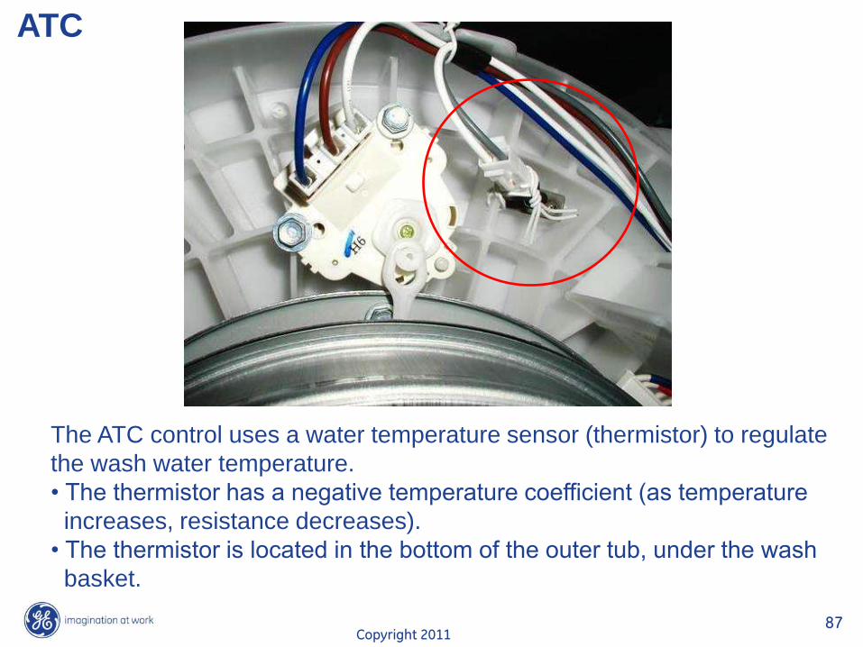
ATC
The ATC control uses a water temperature sensor (thermistor) to regulate
the wash water temperature.
• The thermistor has a negative temperature coefficient (as temperature
increases, resistance decreases).
• The thermistor is located in the bottom of the outer tub, under the wash
basket.
Copyright 2011 88
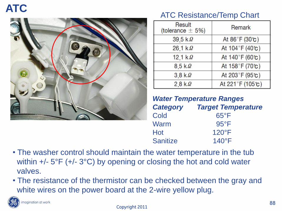
ATC
• The washer control should maintain the water temperature in the tub
within +/- 5°F (+/- 3°C) by opening or closing the hot and cold water
valves.
• The resistance of the thermistor can be checked between the gray and
white wires on the power board at the 2-wire yellow plug.
Water Temperature Ranges
Category Target Temperature
Cold 65°F
Warm 95°F
Hot 120°F
Sanitize 140°F
ATC Resistance/Temp Chart
Copyright 2011 89
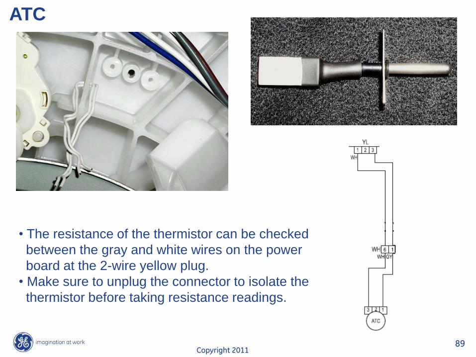
ATC
• The resistance of the thermistor can be checked
between the gray and white wires on the power
board at the 2-wire yellow plug.
• Make sure to unplug the connector to isolate the
thermistor before taking resistance readings.
Copyright 2011 90
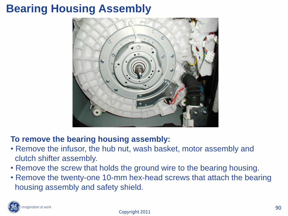
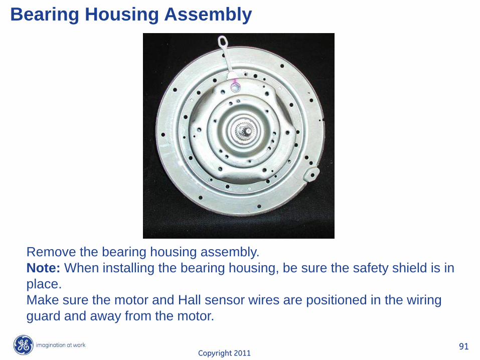
Bearing Housing Assembly
To remove the bearing housing assembly:
• Remove the infusor, the hub nut, wash basket, motor assembly and
clutch shifter assembly.
• Remove the screw that holds the ground wire to the bearing housing.
• Remove the twenty-one 10-mm hex-head screws that attach the bearing
housing assembly and safety shield.
Copyright 2011 91
Bearing Housing Assembly
Remove the bearing housing assembly.
Note: When installing the bearing housing, be sure the safety shield is in
place.
Make sure the motor and Hall sensor wires are positioned in the wiring
guard and away from the motor.
Copyright 2011 92
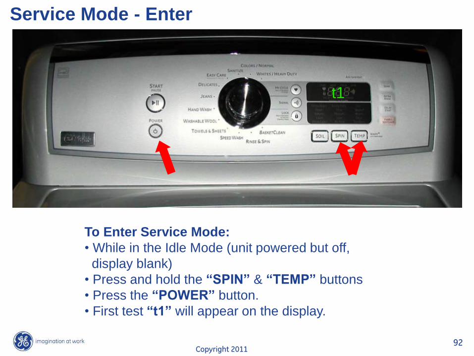
Service Mode - Enter
To Enter Service Mode:
• While in the Idle Mode (unit powered but off,
display blank)
• Press and hold the “SPIN” & “TEMP” buttons
• Press the “POWER” button.
• First test “t1” will appear on the display.
t1
Copyright 2011 93
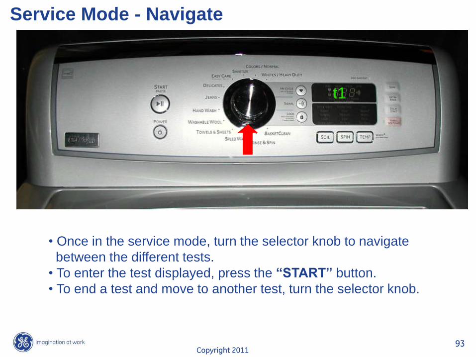
Service Mode - Navigate
• Once in the service mode, turn the selector knob to navigate
between the different tests.
• To enter the test displayed, press the “START” button.
• To end a test and move to another test, turn the selector knob.
t1
Copyright 2011 94
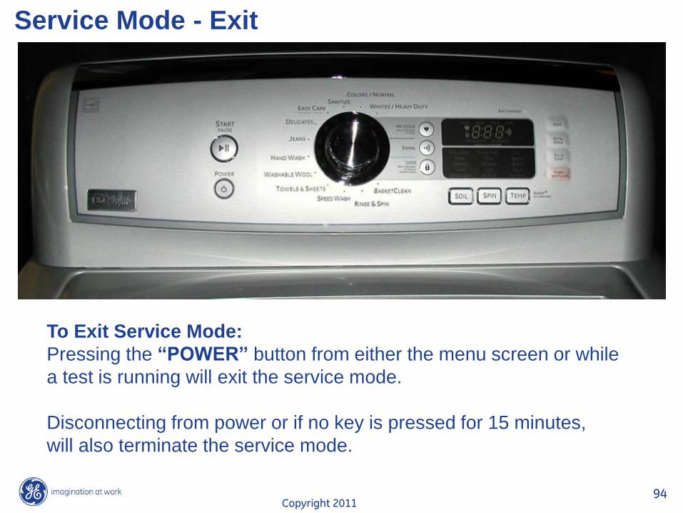
Service Mode - Exit
To Exit Service Mode:
Pressing the “POWER” button from either the menu screen or while
a test is running will exit the service mode.
Disconnecting from power or if no key is pressed for 15 minutes,
will also terminate the service mode.
Copyright 2011 95
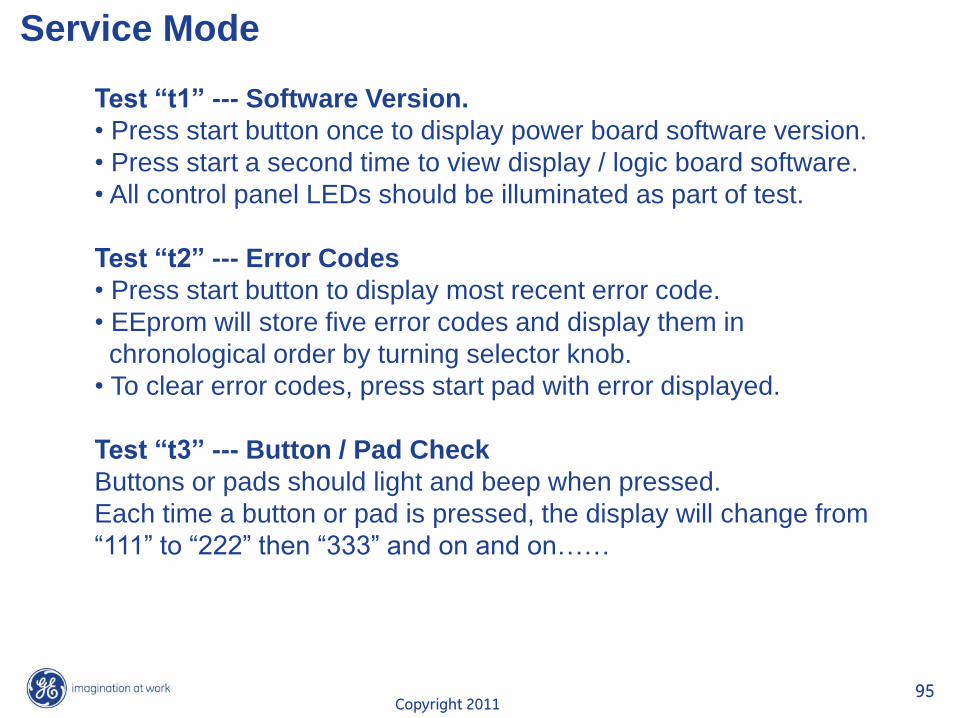
Service Mode
Test “t1” --- Software Version.
• Press start button once to display power board software version.
• Press start a second time to view display / logic board software.
• All control panel LEDs should be illuminated as part of test.
Test “t2” --- Error Codes
• Press start button to display most recent error code.
• EEprom will store five error codes and display them in
chronological order by turning selector knob.
• To clear error codes, press start pad with error displayed.
Test “t3” --- Button / Pad Check
Buttons or pads should light and beep when pressed.
Each time a button or pad is pressed, the display will change from
“111” to “222” then “333” and on and on……
Copyright 2011 96
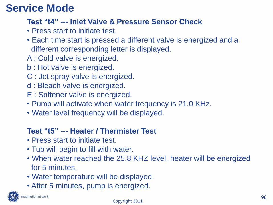
Service Mode
Test “t4” --- Inlet Valve & Pressure Sensor Check
• Press start to initiate test.
• Each time start is pressed a different valve is energized and a
different corresponding letter is displayed.
A : Cold valve is energized.
b : Hot valve is energized.
C : Jet spray valve is energized.
d : Bleach valve is energized.
E : Softener valve is energized.
• Pump will activate when water frequency is 21.0 KHz.
• Water level frequency will be displayed.
Test “t5” --- Heater / Thermister Test
• Press start to initiate test.
• Tub will begin to fill with water.
• When water reached the 25.8 KHZ level, heater will be energized
for 5 minutes.
• Water temperature will be displayed.
• After 5 minutes, pump is energized.
Copyright 2011 97
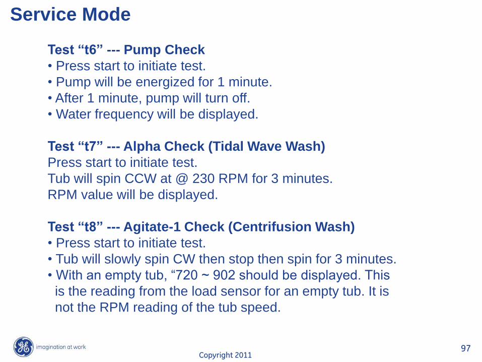
Service Mode
Test “t6” --- Pump Check
• Press start to initiate test.
• Pump will be energized for 1 minute.
• After 1 minute, pump will turn off.
• Water frequency will be displayed.
Test “t7” --- Alpha Check (Tidal Wave Wash)
Press start to initiate test.
Tub will spin CCW at @ 230 RPM for 3 minutes.
RPM value will be displayed.
Test “t8” --- Agitate-1 Check (Centrifusion Wash)
• Press start to initiate test.
• Tub will slowly spin CW then stop then spin for 3 minutes.
• With an empty tub, “720 ~ 902 should be displayed. This
is the reading from the load sensor for an empty tub. It is
not the RPM reading of the tub speed.
Copyright 2011 98
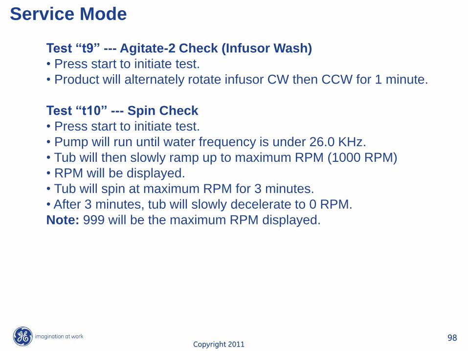
Service Mode
Test “t9” --- Agitate-2 Check (Infusor Wash)
• Press start to initiate test.
• Product will alternately rotate infusor CW then CCW for 1 minute.
Test “t10” --- Spin Check
• Press start to initiate test.
• Pump will run until water frequency is under 26.0 KHz.
• Tub will then slowly ramp up to maximum RPM (1000 RPM)
• RPM will be displayed.
• Tub will spin at maximum RPM for 3 minutes.
• After 3 minutes, tub will slowly decelerate to 0 RPM.
Note: 999 will be the maximum RPM displayed.
Copyright 2011 99
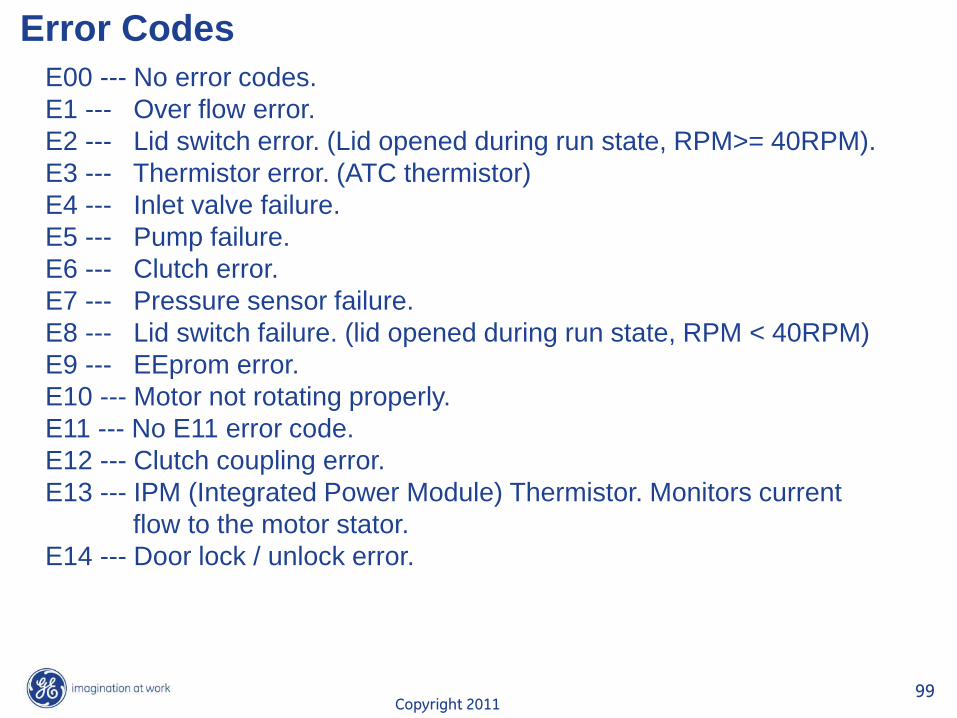
Error Codes
E00 --- No error codes.
E1 --- Over flow error.
E2 --- Lid switch error. (Lid opened during run state, RPM>= 40RPM).
E3 --- Thermistor error. (ATC thermistor)
E4 --- Inlet valve failure.
E5 --- Pump failure.
E6 --- Clutch error.
E7 --- Pressure sensor failure.
E8 --- Lid switch failure. (lid opened during run state, RPM < 40RPM)
E9 --- EEprom error.
E10 --- Motor not rotating properly.
E11 --- No E11 error code.
E12 --- Clutch coupling error.
E13 --- IPM (Integrated Power Module) Thermistor. Monitors current
flow to the motor stator.
E14 --- Door lock / unlock error.
Copyright 2011 100
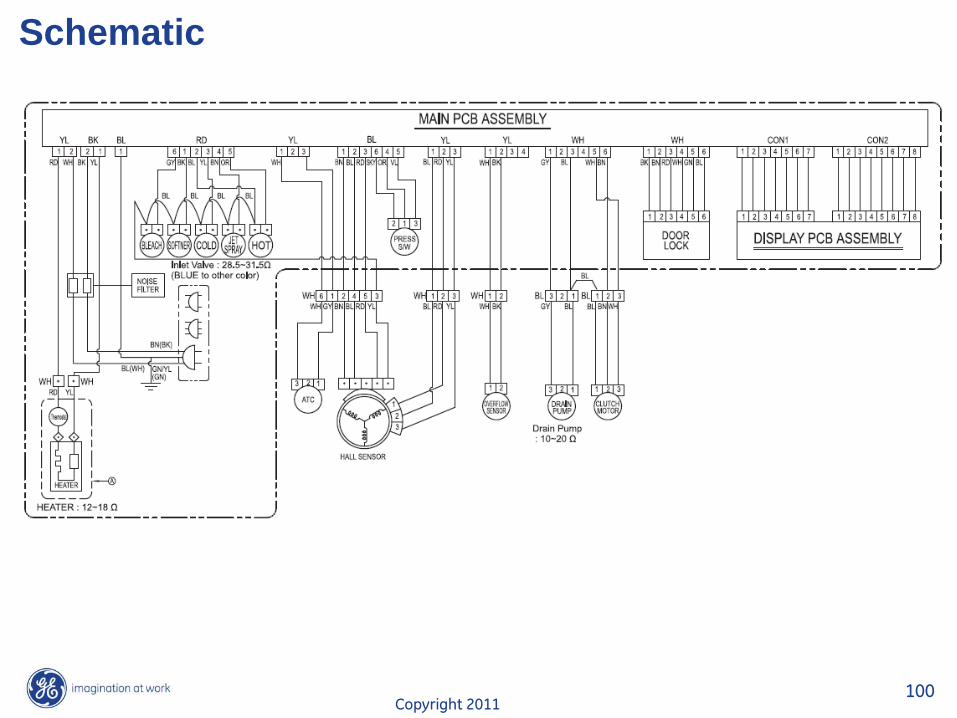
Schematic

Copyright 2011 101
END OF
PRESENTATION
THANK YOU FOR YOUR
ATTENTION …….