Carrier ID Carrier Name Carrier Address1 Carrier Address2 ...
30XB / 30XBP 250-1700
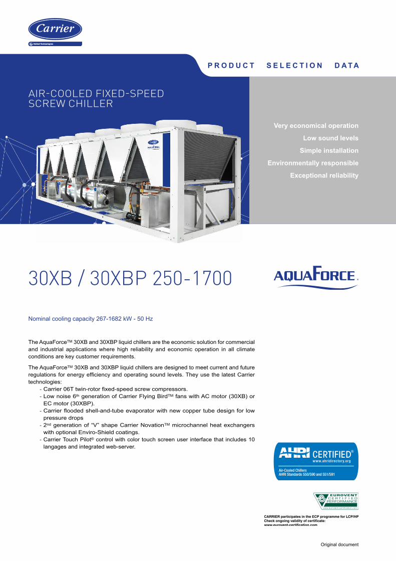
The AquaForceTM 30XB and 30XBP liquid chillers are the economic solution for commercial and industrial applications where high reliability and economic operation in all climate conditions are key customer requirements.
The AquaForceTM 30XB and 30XBP liquid chillers are designed to meet current and future regulations for energy efficiency and operating sound levels. They use the latest Carrier technologies:
- Carrier 06T twin-rotor fixed-speed screw compressors. - Low noise 6th generation of Carrier Flying BirdTM fans with AC motor (30XB) or EC motor (30XBP).
- Carrier flooded shell-and-tube evaporator with new copper tube design for low pressure drops
- 2nd generation of “V” shape Carrier NovationTM microchannel heat exchangers with optional Enviro-Shield coatings.
- Carrier Touch Pilot® control with color touch screen user interface that includes 10 langages and integrated web-server.
Nominal cooling capacity 267-1682 kW - 50 Hz
P R O D U C T S E L E C T I O N D A T A
Original document
Very economical operation
Low sound levels
Simple installation
Environmentally responsible
Exceptional reliability
AIR-COOLED FIXED-SPEED SCREW CHILLER

2
CUSTOMER BENEFITS
The range is available in 3 efficiency levels.
■ 30XB standard unit The AquaForceTM 30XB is equipped with fixed-speed screw
compressors and fixed-speed fans with AC motors. The 30XB offers an economical solution whilst providing high full load efficiency for process applications and operation in high ambients.
(Average SEPR of 5.2, average SEER of 4.2, average EER of 3.1)
■ 30XBwith variable-speed AC fan motors (Option 17) The 30XB with variable-speed AC fan motors offers an economical solution to enhance seasonal energy efficiency levels for comfort applications.
(Average SEPR of 5.5, average SEER of 4.3, average EER of 3.1)
■ 30XBP premium unit The 30XBP premium unit is equipped with EC fans and
additional heat exchange surface to improve both the full load and part load energy efficiency. The 30XBP provides very cost effective operation in both process and comfort applications through the use of state of the art EC fan technology. (Average SEPR of 5.9, average SEER of 4.4, average EER of 3.2)
Very economical operationExceptionally high full load and part load energy efficiency:
- 30XB version with Eurovent energy efficiency class A and B, ESEER up to 4.3 and SEER 12/7°C up to 4.4 with option 17 in accordance with EN14825.
- 30XBP version with Eurovent energy efficiency class A, ESEER up to 4.4 and SEER 12/7°C up to 4.6 in accordance with EN14825.
- Twin-rotor screw compressor equipped with a high-efficiency motor and a variable capacity valve that permits exact matching of the cooling capacity to the load.
- NovationTM aluminium condenser with high-efficiency micro-channels.
- Flooded shell-and-tube evaporator with new generation of cooler tubes to reduce exchanger pressure drops, especially in applications with high percentage of glycol.
- Electronic expansion device permitting operation at a lower condensing pressure and improved utilisation of the evaporator heat exchange surface (superheat control).
- Economiser system with electronic expansion device for increased cooling capacity.
Low operating sound levels ■ Compressors
- Discharge dampers integrated in the oil separator (Carrier patent).
- Silencer on the economiser return line. - Compressor and oil separator acoustic enclosure, reducing radiated noise (option).
■ Condenser section - Condenser coils in wide angle V configuration, allowing quieter air flow across the coil
- Low-noise 6th generation Flying Bird fans, made of a composidte material (Carrier patent), are now even quieter and do not generate intrusive low-frequency noise
- Inverter driven EC fans on 30XBP version eliminate start stop noise during part load operation.
- Rigid fan mounting preventing start-up noise (Carrier patent).
Simple installation ■ Integrated hydraulic module (option)
- Centrifugal low or high-pressure water pump (as required), based on the pressure loss of the hydraulic installation
- Single or dual pump (as required) with run time balancing and automatic changeover to the back-up pump if a fault develops
- Water filter to protect pump against circulating debris - High-capacity membrane expansion tank ensures pressurisation of the water circuit
- Thermal insulation and aluminium cladding (option) - Pressure sensor to check filter condition and for direct numerical display of the water flow rate with an estimate of the instantaneous cooling capacity at the control interface
- Water flow control valve.
■ Simplified electrical connections - Main disconnect switch with high trip capacity - Transformer to supply the integrated control circuit (400/24 V).
■ Fast commissioning - Systematic factory operation test before shipment - Quick-test function for step-by-step verification of the controls, expansion devices, fans and compressors.
Environmental responsibility ■ R-134a refrigerant
- Range designed for use with R-134a refrigerant with the possibility to upgrade to ultra-low global warming potential R-1234ze refrigerant on site in the future.
- 40% reduction in the refrigerant charge through the use of micro-channel heat exchangers
■ Leak-tight refrigerant circuit - Reduction of leaks as no capillary tubes and flare connections are used
- Verification of pressure transducers and temperature sensors without transferring refrigerant charge
- Liquid line service valve for simplified maintenance (option).
Exceptional reliability ■ Screw compressors
- Industrial-type screw compressors with oversized bearings and motor cooled by suction gas.
- All compressor components are easily accessible on site minimising down-time.
- Dedicated electronic compressor protection module.
■ Air condenser 2nd generation of "V" shape Carrier NovationTM aluminium
microchannel heat exchangers (MCHE) with high corrosion resistance. The all aluminium design eliminates the formation of galvanic currents between aluminium and copper that cause coil corrosion in saline or corrosive environments.
■ Evaporator Thermal insulation with aluminium sheet finish (option) for
improved resistance to mechanical and UV damage.
■ Auto-adaptive control - Control algorithm prevents excessive compressor cycling (Carrier patent)
- Automatic compressor unloading in case of abnormally high condensing pressure. If condenser coil fouling or fan failure occurs, the Aquaforce continues to operate, but at reduced capacity
■ Exceptional endurance tests - Partnerships with specialised laboratories and use of sophisticated finite element stress analysis for the design of critical components.
- Transport simulation test in the laboratory on a vibrating table. The test is based on a military standard and equivalent to 4000 km by truck.
- Salt mist corrosion resistance test in the laboratory for increased corrosion resistance.

3
TECHNICAL INSIGHTS
Touch Pilot Control
Touch Pilot, user interface
■ New innovative smart control features: - An intuitive and user-friendly, coloured, 5'' interface (7" optional)
- Direct access to the unit's technical drawings and the main service documents
- Screen-shots with concise and clear information in local languages
- Complete menu, customised for different users (end user, service personnel and Carrier-factory technicians)
- Easy access to the control panel with inclined touch screen mounting to ensure legibility under any lighting conditions
- Safe operation and unit setting: password protection ensures that unauthorised people cannot modify any advanced parameters
- Simple and "smart" intelligence uses data collection from the constant monitoring of all machine parameters to optimise unit operation.
■ Energy management: - Internal time schedule clock controls chiller on/off times and operation at a second set-point
- The DCT (Data Collection Tool) records the alarms history to simplify and facilitate service operations.
Remote Management (Standard)
■ Units with Touch Pilot control can be easily accessed from the internet, using a PC with an Ethernet connection. This makes remote control quick and easy and offers significant advantages for service operations.
■ Aquaforce is equipped with an RS485 serial port that offers multiple remote control, monitoring and diagnostic possibilities. When networked with other Carrier equipment through the CCN (Carrier Comfort Network - proprietary protocol), , and in conjunction with one of Carrier’s network products (Chiller System Manager or Plant system Manager) it forms part of a fully integrated and balanced HVAC system (optional).
■ Aquaforce also communicates with other building management systems via optional communication gateways.
■ The following commands/visualisations are possible from remote connection:
- Start/stop of the machine - Dual set-point management: through a dedicated contact is possible to activate a second set-point (for example, during unoccupied mode).
- Demand limit setting: to limit the maximum chiller capacity to a predefined value
- Water pump control: these outputs control the contactors of one/two evaporator water pums
- Automatic changeover of pumps in the event of a fault (only with options 116C/116G).
- Operation visualisation: indication if the unit is operating or in stand-by (no cooling load), (no cooling load) - alarm visualisation.
Remote Management (EMM option)
■ The Energy Management Module (EMM) offers extended remote control possibilities:
- Room temperature: Permits set-point reset based on the building indoor air temperature (if Carrier thermostat are installed)
- Set-point reset: Allows reset of the cooling set-point based on a 4-20 mA or 0-10 V signal
- Demand limit: Permits limitation of the maximum chiller capacity based on 0-10 V signal
- Demand limit 1 and 2: Closing of these contacts limits the maximum chiller capacity to two predefined values
- User safety: This contact can be used for any customer safety loop; opening the contact generates a specific alarm
- Ice storage end: When ice storage has finished, this input permits return to the second set-point (unoccupied mode)
- Time schedule override: closing this contact cancels the programmed time schedule.
- Out of service: This signal indicates that the chiller is completely out of service
- Chiller capacity: This analogue output (0-10 V) gives an immediate indication of the chiller capacity
- Alert indication: This volt-free contact indicates the necessity to carry out a maintenance operation or the presence of a minor fault
- Compressors running status: Set of outputs (one for each compressor) indicating which compressors are running.

4
TECHNICAL INSIGHTS
06T Screw Compressor
99.7%* of units without a compressor failure* Quality rate measured over a period of 15 years operation
The Carrier 06T screw compressor benefits from Carrier’s long experience in the development of twin-rotor screw compressors. The compressor is equipped with bearings with oversized rollers, oil pressure lubricated for reliable and durable operation, even at maximum load.
A variable control valve controlled by the oil pressure permits infinitely variable cooling capacity. This system allows optimal adjustment of the compressor cooling capacity and ensures exceptionally high stability of the chilled water leaving temperature.
Among the other advantages: if a fault occurs e.g. if the condenser is fouled or at very high outside temperature, the compressor does not switch off, but continues operation with a reduced capacity (unloaded mode).
The compressor is equipped with a separate oil separator that minimises the amount of oil in circulation in the refrigerant circuit and, with its integrated silencer, considerably reduces discharge gas pulsations for much quieter operation.
Novation® Heat Exchangers with Micro-Channel coil Technology
Already utilised in the automobile and aeronautical industries for many years, the NovationTM MCHE micro-channel heat exchanger used in the Aquaforce is entirely made of aluminium. This one-piece concept significantly increases its corrosion resistance by eliminating the galvanic currents that are created when two different metals (copper and aluminium) come into contact in traditional heat exchangers. Unlike traditional heat exchangers the NovationTM MCHE heat exchanger can be used in moderate marine and urban environments (Carrier recommendation).
From an energy efficiency point-of-view the NovationTM MCHE heat exchanger is approximately 10% more efficient than a traditional coil and allows a 40% reduction in the amount of refrigerant used in the chiller. The low thickness of the NovationTM
MCHE reduces air pressure losses by 50% and makes it susceptible to very little fouling (e.g. by sand). Cleaning of the NovationTM MCHE heat exchanger is very fast using a high-pressure washer.
Carrier Novation® MCHE with Super Enviro-shield® coating, the ideal customer choice
To further enhance long-term performance, and to protect coils from early deterioration, Carrier offers (as options) dedicated treatments for installations in corrosive environments.
The NovationTM MCHE with Enviro-Shield protection (option 262) are recommended for installations in moderately corrosive environments. The Enviro-Shield protection utilises corrosion inhibitors which actively arrest oxidation in case of mechanical damage.
The NovationTM MCHE with the exclusive Super Enviro-Shield protection (option 263) are recommended for installations in corrosive environments. The Super Enviro-Shield protection consist in an extremely durable and flexible epoxy coating uniformly applied over all coil surfaces for complete isolation from the contaminated environment.

5
TECHNICAL INSIGHTS
Novation® Heat Exchangers with Micro-Channel coil Technology
After a total of more than 7,000 hours of testing following various test standards in UTC laboratories, the Carrier Novation® MCHE with Super Enviro-shield® coating appears to be the ideal customer choice to minimize the harmful effects of corrosive atmospheres and ensure long equipment life.
- Best corrosion resistance per ASTM B117/D610 test - Best heat transfer performance per Carrier Marine 1 test - Proven reliability per ASTM B117 test
Coil Types(ranked by performance)
Visual Corrosion Evaluation
Heat Transfer Performance Degradation Time to Failure Test Campaign
Conclusions
Super Enviro-shield® Novation™ MCHE Very good Very good No coil leak BestSuper Enviro-shield® Cu/Al coil Very good Good No coil leak Very goodEnviro-shield® Novation™ MCHE Very good Good No coil leak Very goodAl/Al coil Very good Good No coil leak Very goodNovation™ MCHE Good Good No coil leak GoodCu/Cu coil Good Good Leak AcceptableBlygold® Cu/Al coil Good Good No coil leak AcceptablePrecoat Cu/Al coil Bad Bad No coil leak BadCu/Al coil Bad Bad No coil leak Bad
New Generation of Flying Bird VI fans with EC motor
The 30XB and 30XBP utilize Carrier’s 6th generation Flying BirdTM fan technology, engineered for maximum efficiency, super low noise, and wide operating range. The fan includes Carrier patented rotating shroud technology and back-swept blades with a unique wave-serration trailing edge inspired from nature.
It was designed and optimized for the 30XB air management system configuration and heat exchanger technology and is offered with induction and EC motor options. The fan meets the latest European eco-design requirements for fan efficiency. The fan uses Carrier’s robust and proven injection molded composite-thermoplastic construction.
6
OPTIONS
Options No. Description Advantages Use for 30XB / 30XBP
Coil with anti-corrosion post treatment
2BFactory application of Blygold Polual treatment on the copper/aluminum coils
Improved corrosion resistance, recommended for industrial, rural and marine environments
30XB/30XBP 250-1700
Corrosion protection, traditional coils
3AFins made of pre-treated aluminum (polyurethane and epoxy)
Improved corrosion resistance, recommended for moderate marine and urban environments
30XB/30XBP 250-1700
Medium-temperature brine solution
5
Implementation of new control algorithms and redesigned evaporator to allow chilled brine solution production down to -12°C when ethylene glycol is used (-8°C with propylene glycol)
Covers specific applications such as ice storage and industrial processes
30XB/30XBP 250-1700
Low-temperature brine solution 6
Implementation of new control algorithms and redesigned evaporator to allow chilled brine solution production down to -15°C when ethylene glycol is used (-10°C with propylene glycol)
Covers specific applications such as ice storage and industrial processes
30XB/30XBP 250-1700
Light-brine solution, down to -3°C
8Implementation of new control algorithms to allow chilled brine solution production down to -6°C when ethylene glycol is used (-3°C with propylene glycol)
Matches with most application requirements for ground-sourced heat pumps and fits with many industrial processes requirements
30XB/30XBP 250-1700
Unit equipped for air discharge ducting
10Fans equipped with discharge connection flanges - maximum available pressure 60 Pa
Facilitates connections to the discharge ducts30XB/30XBP
250-1700
Low noise level 15 Aesthetic and sound absorbing compressor enclosure Noise level reduction30XB/30XBP
250-1700
Very low noise level 15LSAesthetic and sound absorbing compressor enclosure associated with low-speed fans
Noise level reduction in sensitive environments30XB/30XBP
250-1700
Ultra low noise level 15LS+Acoustic compressor enclosure, low-speed fans and enhanced sound insulation of main noise sources
Noise level reduction in sensitive environments 30XB 250-1700
Variable speed fans 17 Unit equipped with variable speed fansEnhances the unit seasonal energy efficiency performance and reduces the noise emission thanks to a smooth fan speed variation.
30XB 250-1700
IP54 control box 20A Increased leak tightness of the unitProtects the inside of the electrical box from dust, water and sand. In general this option is recommended for installations in polluted environments
30XB/30XBP 250-1700
Tropicalisation of the electrical box
22
Electrical box equipped with an electrical heater and a fan. Electrical connections on the compressors painted with a special varnish and covered with an anti-condensation foam.
Allows safe operation in typical "tropical" climate. This option is recommended for all applications where humidy inside the electrical box can reach 80% at 40°C and unit can remain in stand-by for a long time under these conditions.
30XB/30XBP 250-1700
Grilles and enclosure panels 23Metal grilles on the 4 unit sides, plus side enclosure panels at each end of each coil
Improves aesthetics, protection against intrusion to the unit interior, coil and piping protection against impacts.
30XB/30XBP 250-1700
Enclosure panels 23A Side enclosure panels at each end of each coilImproves aesthetics, coil and piping protection against impacts.
30XB/30XBP 250-1700
Low inrush current 25CSpecific compressor loading and unloading sequence to limit the unit start-up current
Reduced start-up current30XB/30XBP
250-1700Winter operation down to -20°C 28 Fan speed control via frequency converter Stable unit operation for air temperature down to -20°C 30XB 250-1700
Water exchanger frost protection 41AElectric resistance heater on the water exchanger and discharge valve
Water exchanger frost protection down to -20°C outside temperature
30XB/30XBP 250-1700
Evaporator & hydraulic module frost protection
41BElectric resistance heater on water exchanger, discharge valve and hydraulic module
Water exchanger and hydraulic module frost protection down to -20°C outside temperature
30XB/30XBP 250-500
Total heat recovery 50Unit equipped with additional heat exchanger in parallel with the condenser coils.
Production of free hot-water simultaneously with chilled water production
30XB/30XBP 250-1000
Master/slave operation 58
Unit equipped with supplementary water outlet temperature sensor kit (to be field installed) allowing master/slave operation of two units connected in parallel
Optimised operation of two units connected in parrallele operation with operating time equalisation
30XB/30XBP 250-1700
Single power connection point 81 Unit power connection via one main supply connection Quick and easy installation30XB/30XBP 1100-1550
Service valve set 92Liquid line valve (evaporator inlet), compressor suction and discharge line valves and economiser line valve
Allow isolation of various refrigerant circuit components for simplified service and maintenance
30XB/30XBP 250-1700
Compressor discharge valves 93A Shut-off valve on the compressor discharge piping Simplified maintenance30XB/30XBP
250-1700
Evaporator with one pass more 100A Evaporator with one pass more on the water side Optimise chiller operation when the chilled water circuit is designed with low waterflows (high evaporator delta T)
30XB/30XBP 250-1700
Evaporator with one pass less 100CEvaporator with one pass less on the water side. Evaporator inlet and outlet on opposite sides.
Easy to install, depending on site. Reduced pressure drops
30XB/30XBP 250-1000
21 bar evaporator 104Reinforced evaporator for extension of the maximum water-side service pressure to 21 bar (standard 10 bar)
Covers applications with a high water column evaporator side (typically high-rise buildings)
30XB/30XBP 250-1700
Reversed evaporator water connections
107 Evaporator with reversed water inlet/outlet Easy installation on sites with specific requirements30XB/30XBP
250-1700
HP single-pump hydraulic module
116B
Complete hydraulic module equipped with water filter, expansion tank with relief valve, one high pressure pump, drain valve and water flow control valve. For more details, refer to the dedicated chapter
Easy and fast installation (plug & play).Increased system reliability
30XB/30XBP 250-500
HP dual-pump hydraulic module 116C
Complete hydraulic module equipped with water filter, expansion tank with relief valve, two high pressure pumps, drain valve and water flow control valve. For more details, refer to the dedicated chapter
Easy and fast installation (plug & play).Increased system reliability
30XB/30XBP 250-500

7
Options No. Description Advantages Use for 30XB / 30XBP
LP single-pump hydraulic module
116F
Complete hydraulic module equipped with water filter, expansion tank with relief valve, one low pressure pump, drain valve and water flow control valve. For more details, refer to the dedicated chapter
Easy and fast installation (plug & play).Increased system reliability
30XB/30XBP 250-500
LP dual-pump hydraulic module 116G
Complete hydraulic module equipped with water filter, expansion tank with relief valve, two low pressure pumps, drain valve and water flow control valve. For more details, refer to the dedicated chapter
Easy and fast installation (plug & play).Increased system reliability
30XB/30XBP 250-500
Dx Free Cooling system on two circuits
118A
Patented Carrier free-cooling system with cooling micro-pump on both refrigerant circuits. Operation without glycol, no extra free-cooling coil. See Dx Free-cooling option chapter
Energy savings for applications with cooling demand throughout the entire year
30XB/30XBP 250-1000
J-Bus gateway 148BBi-directional communication board complying with JBus protocol
Connects the unit by communication bus to a building management system
30XB/30XBP 250-1700
Lon gateway 148DBi-directional communication board complying with Lon Talk protocol
Connects the unit by communication bus to a building management system
30XB/30XBP 250-1700
Bacnet over IP 149Bi-directional high-speed communication using BACnet protocol over Ethernet network (IP)
Easy and high-speed connection by ethernet line to a building management system. Allows access to multiple unit parameters
30XB/30XBP 250-1700
Energy Management Module 156EMM Control board with additional inputs/outputs. See Energy Management Module option chapter
Extended remote control capabilities (Set-point reset, ice storage end, demand limits, boiler on/off command...)
30XB/30XBP 250-1700
7" user interface 158AControl supplied with a 7 inch colour touch screen user interface
Enhanced ease of use.30XB/30XBP
250-1700
Input contact for Refrigerant leack detection
1590-10 V signal to report any refrigerant leakage in the unit directly on the controlller (the leak detector itself must be supplied by the customer)
Immediate customer notification of refrigerant losses to the atmosphere, allowing timely corrective actions
30XB/30XBP 250-1700
Dual relief valves on 3-way valve 194Three-way valve upstream of dual relief valves on the evaporator and the oil separator
Valve replacement and inspection facilitated without refrigerant loss. Comforms to European standard EN378/BGVD4
30XB/30XBP 250-1000
Compliance with Swiss regulations
197Additional tests on the water heat exchangers: supply (additional of PED documents) supplementary certificates and test certifications
Conformance with Swiss regulations30XB/30XBP
250-1700
Compliance with Russian regulations
199 EAC certification Conformance with Russian regulations30XB/30XBP
250-1700Compliance with Australian regulations
200 Unit approved to Australian code Conformance with Australian regulations30XB/30XBP
250-1700
Power factor correction 231Capacitors for automatic regulation of power factor (cos phi) value to 0,95.
Reduction of the apparent electrical power, compliance with minimum power factor limit set by utilities
30XB/30XBP 250-1000
Traditional coils (Cu/Al) 254 Coils made of copper tubes with aluminum fins None30XB 250-1700 (not available for
size 1500)
Traditional coils (Cu/Al) without slots
255Coils made of copper tubes with aluminum fins without slots
None30XB 250-1700 (not available for
size 1500)Insulation of the evap. in/out ref.lines
256Thermal insulation of the evaporator entering/leaving refrigerant lines with flexible, UV resistant insulation
Prevents condensation on the evaporator entering/leaving refrigerant lines
30XB/30XBP 250-1700
Enviro-Shield anti-corrosion protection
262
Coating by conversion process which modifies the surface of the aluminum producing a coating that is integral to the coil. Complete immersion in a bath to ensure 100% coverage. No heat transfer variation, tested 4000 hours salt spray per ASTM B117
Improved corrosion resistance, recommended for use in moderately corrosive environments
30XB/30XBP 250-1700
Super Enviro-Shield anti-corrosion protection
263
Extremely durable and flexible epoxy polymer coating applied on micro channel heat exchangers by electro coating process, final UV protective topcoat. Minimal heat transfer variation, tested 6000 hours constant neutral salt spray per ASTM B117, superior impact resistance per ASTM D2794
Improved corrosion resistance, recommended for use in extremely corrosive environments
30XB/30XBP 250-1700
Welded evaporator connection kit
266 Victaulic pipe adapters for welded joints Easy installation30XB/30XBP
250-1700
Compressor enclosure 279a Compressor enclosure Improved aesthetic, compressor protection against external elements (dust, sand, water…)
30XB/30XBP 250-1700
Evaporator with aluminum jacket 281Evaporator covered with an aluminum sheet for thermal insulation protection
Improved resistance to aggressive climate conditions30XB/30XBP
250-1700
230V electrical plug 284230V AC power supply source provided with plug socket and transformer (180 VA, 0,8 Amps)
Permits connection of a laptop or an electrical device during unit commissioning or servicing
30XB/30XBP 250-1700
Carrier Connect link (only European distribution companies)
298
3G router board NOTE 1: require option 149 NOTE 2: when more than one machine is installed on site, only one of them shall be equipped with option 298 while all of them must be equipped with option 149 NOTE 3: if the Carrier® PlantCTRL™ is on site, option 298 shall be integrated in the Carrier® PlantCTRL™ while option 149 is still mandatory for each single unit.
Enabler for Carrier Connect service offer30XB/30XBP
250-1700
Compliance with UAE regulation 318Additional label on the unit with rated power input, rated current and EER following AHRI 550/590
Compliance with ESMA standard UAE 5010-5 :2014. 30XB/30XBP
250-1700Compliance with Qatar regulation
319Specific nameplate on the unit with power supply 415 V+/-6%
Compliance with KAHRAMAA regulation in Qatar.30XB/30XBP
250-1700
OPTIONS
8
HYDRAULIC MODULE (OPTIONS 116B, C, F, G)
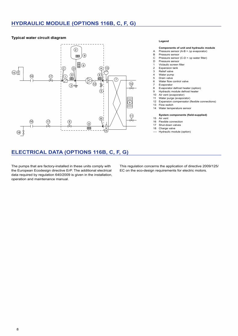
Typical water circuit diagram
1
2
17
16
18
1 2
9
99
11
1012
14
A
5
15
9
9
167
8
17
13
B
C D
6
4
3
ELECTRICAL DATA (OPTIONS 116B, C, F, G)
The pumps that are factory-installed in these units comply with the European Ecodesign directive ErP. The additional electrical data required by regulation 640/2009 is given in the installation, operation and maintenance manual.
This regulation concerns the application of directive 2009/125/EC on the eco-design requirements for electric motors.
Legend
Components of unit and hydraulic moduleA Pressure sensor (A-B = ∆p evaporator)B Pressure sensorC Pressure sensor (C-D = ∆p water filter)D Pressure sensor1 Victaulic screen filter2 Expansion tank3 Relief valve4 Water pump5 Drain valve6 Water flow control valve7 Evaporator8 Evaporator defrost heater (option)9 Hydraulic module defrost heater10 Air vent (evaporator)11 Water purge (evaporator)12 Expansion compensator (flexible connections)13 Flow switch14 Water temperature sensor
Systemcomponents(field-supplied)15 Air vent16 Flexible connection17 Shut-down valves18 Charge valve---- Hydraulic module (option)

9
PUMP CURVE (OPTIONS 116B, C, F, G)
Conditions and limits of use:
- Fresh water 20°C - In case of use of the glycol, the maximum water flow is reduced. - When the glycol is used, it’s limited to 40%.
Single pump low pressure Dual pump low pressure
Water flow rate, l/s
Ava
ilabl
e st
atic
pre
ssur
e, k
Pa
200
180
160
140
120
100
80
60
40
20
03 5 7 9 11 13 15 17 19 21 23 25 27 29 31
a b c d e f
Water flow rate, l/s
Ava
ilabl
e st
atic
pre
ssur
e, k
Pa
200
180
160
140
120
100
80
60
40
20
03 5 7 9 11 13 15 17 19 21 23 25 27 29
a b c d e f
1 30XB/XBP 250 4 30XB/XBP 400
2 30XB/XBP 300 5 30XB/XBP 450
3 30XB/XBP 350 6 30XB/XBP 500
1 30XB/XBP 250 4 30XB/XBP 400
2 30XB/XBP 300 5 30XB/XBP 450
3 30XB/XBP 350 6 30XB/XBP 500
Single pump high pressure Dual pump high pressure
Water flow rate, l/s
Ava
ilabl
e st
atic
pre
ssur
e, k
Pa
400
350
300
250
200
150
100
50
03 5 7 9 11 13 15 17 19 21 23 25 27 29 31 33 35
a bc
d
e f
Water flow rate, l/s
400
350
300
250
200
150
100
50
03 5 7 9 11 13 15 17 19 21 23 25 27 29 31 33
Ava
ilabl
e st
atic
pre
ssur
e, k
Pa
ab
c d ef
1 30XB/XBP 250 4 30XB/XBP 400
2 30XB/XBP 300 5 30XB/XBP 450
3 30XB/XBP 350 6 30XB/XBP 500
1 30XB/XBP 250 4 30XB/XBP 400
2 30XB/XBP 300 5 30XB/XBP 450
3 30XB/XBP 350 6 30XB/XBP 500

10
TOTAL HEAT RECLAIM (OPTION 50)
Suitable for heating, domestic hot water production, agriculture and food industry, industrial processes and other hot-water requirements.
With the total heat reclaim option it is possible to reduce the energy consumption bill considerably, when compared to conventional heating equipment such as fossil fuel boilers or electric water tanks.
Operating principle
If hot water production is required, the compressor discharge gases are directed towards the heat reclaim condenser. The refrigerant releases its heat to the hot water that leaves the condenser at a temperature of up to 60°C. In this way 100% of the heat rejected by the liquid chiller can be used to produce hot water. When the demand for heat is satisfied, the hot gas is again directed towards the air condenser where the heat is rejected to the outside air by the fans. Hot water temperature control is ensured by the chiller Touch Pilot control that independently controls the reclaim operation of each refrigerant circuit.
NOTE: Heat reclaim is only possible, possible if the unit is producing cooling at the same time.
Condenser water temperature (°C) Minimum Maximum
Entering temperature at start-up 12.5* 55
Entering temperature during operation 20 55
Leaving temperature during operation 25 60
Evaporator water temperature (°C) Minimum Maximum
Entering temperature at start-up - 45
Entering temperature during operation 6.8 21
* The entering water temperature at start-up must not fall below 12.5°C. For installations with a lower temperature a three-way valve must be used.Note: If the evaporator leaving water temperature is below 4°C, a glycol-water
solution or the frost protection option must be used.
In part-load operation, the limitation of the condenser leaving water temperature is due to the operating range of the screw compressor. If the condenser leaving water temperature is above the limit value given in the curves below, the unit will automatically change over to air-cooled operating mode:
Con
dens
er le
avin
g w
ater
tem
pera
ture
,°C
Evaporator leaving water temperature,°C
Full load Part load limit, approx. 60% Minimum load limit, approx. 30%
Part load operating limits (evaporator leaving water temperature = 7°C)
Max
imum
con
dens
er le
avin
gw
ater
tem
pera
ture
,°C
Unit load, %

11
DX FREE COOLING SYSTEM (OPTION 118A)
The DX free cooling option permits significant energy savings for all applications that require cooling in winter. In the free cooling mode the compressors are stopped and only the fan and refrigerant micro-pump are running. The changeover from compressor cooling mode to free cooling mode is automatically controlled by the Touch Pilot control, based on the chiller cooling load and the temperature difference between chilled water and ambient air.
IMPORTANT: In order to optimise chiller performance, it is recommended to use the leaving water set point reset function.
Operating principle
When the chilled water to air temperature difference exceeds a threshold value, the Touch Pilot control carries out a comparison between the instantaneous chiller cooling capacity and the available free cooling capacity. If the operating conditions allow free cooling operation, the compressors are stopped, a set of valves on the suction piping connects the evaporator with the condenser, allowing the migration of the refrigerant gas to the condenser. The refrigerant condenses in the condenser coils, and the refrigerant micro-pump transfers the liquid to the evaporator. The cooling capacity in free cooling mode is controlled by the opening of the electronic expansion valve (EXV).
Operation in combined FC (free-cooling) and MC (mechanical cooling) mode is possible in the two independent refrigerant circuits. This can optimise the free-cooling operation and at the same time ensures that the cooling requirements of the system are met.
EER
Delta T (K)
MC modeCircuit 1: MCCircuit 2: MC
Mixed modeCircuit 1: MCCircuit 2: FC
FC modeCircuit 1: FCCircuit 2: FC
LegendMC Mechanical cooling (compressors)FC Free coolingDelta T Difference between the leaving water temperature and the entering air
temperature, K
Advantages of the DX free cooling system
■ Operation without glycol Unlike traditional hydraulic free-cooling systems that require the
use of a glycol solution, the Aquaforce DX free cooling chiller works with pure water. The evaporator is protected against frost down to -20°C by an electric resistance heater (option).
■ Low water pressure losses The Aquaforce DX free cooling chiller does not include a
three-way valve nor free cooling coils connected in series with the evaporator. The Aquaforce free cooling chiller has the same water pressure losses as a standard chiller.
■ Weight and dimensions gain - The DX free cooling option has practically no impact on the weight of the liquid chiller.
- The Aquaforce free cooling chiller has the same dimensions as a standard chiller.
■ Increased energy efficiency - In free cooling mode only the fans and the refrigerant micro-pump run. At an air-water temperature difference of 10K, for example, the average chiller energy efficiency (EER) is 23 (kW/kW).
- In the mechanical cooling mode chiller cooling capacity and efficiency are not compromised by the use of a water-glycol solution.
- As the pressure losses of the water circuit are low, the water pumps use less energy.
COOLING CAPACITIES
30XB &30XBP 250 to 1000 in Free Cooling mode (Option 118A)
LWT (10°C)
Condenser entering air temperature,°C
0 -5 -10Qc EER Qc EER Qc EERkW kW/kW kW kW/kW kW kW/kW
250 143 21,9 183 27,7 186 28,0300 143 22,3 183 28,3 186 28,5350 143 22,0 183 27,9 186 28,1400 183 20,2 255 27,9 275 29,8450 183 20,0 255 27,7 275 29,6500 203 19,9 284 27,7 307 29,6600 253 19,7 373 28,7 416 31,7700 277 20,2 408 29,5 454 32,6750 272 19,9 400 29,1 446 32,2800 275 19,7 405 28,8 451 31,8850 324 19,9 477 29,1 531 32,2900 328 20,4 483 29,8 538 32,91000 368 20,6 542 30,2 604 33,3
Note: Calculations according to the standard performances (in accordance with EN14511-3:2011) and Eurovent-certified. Evaporator fouling factor 0 m2 K/W.
LegendLWT Leaving water temperature,°CQc Cooling capacity, kWEER Energy efficiency ratio, kW/kW
OPERATING LIMITS
Cooling mode
Evaporator Minimum MaximumEntering water temperature at start-up °C - 45Entering water temperature during operation °C 6,8 21Leaving water temperature during operation °C 3,3 15Condenser (air) Minimum MaximumOutdoor ambient operating temperature °C -10 55*With winter operation option (option 28) °C -20 55*
Free-cooling mode
Evaporator Minimum MaximumEntering water temperature at start-up °C - 45Leaving water temperature during operation °C 3,3 26*Condenser (air) Minimum MaximumOutdoor ambient operating temperature °C -10 20With winter operation option (option 28) °C -20 20
* Maximum configurable set-point

12
FAN WITH AVAILABLE PRESSURE (OPTION 10)
This option allows a duct connection at the discharge side of the condenser fan. The unit is equipped with a duct connection frame. The chiller can operate at a static discharge pressure of up to 60 Pa with reduced performance. The performance can be estimated using the coefficients below, applicable at the conditions shown in the curve below.
Selection method
The base performances for the calculation are those of option 119 (only NovationTM MCHE heat exchangers, see pages 24 and 25 of this manual). To obtain the capacities at the static duct pressure, apply the coefficients shown in the table below.
30XB option 10
Correction factors
Fan pressure drop Pa 0 20 40 60
Airflow % 0 -3,5% -7,5% -12,1%Cooling capacity % 0 -0,5% -1,0% -1,5%EER % 0 -1,5% -3,5% -5,0%Power input % 0 +1,0% +2,5% +3,5%
Note: All fans must be individually ducted.
Example
30XB-0800 with 40 Pa pressure drop
Performance at the following conditions: - 35°C outside air temperature - 12/7°C entering/leaving water temperature
30XB option 10
0 Pa Correction factors 40 Pa
Airflow l/s 57840 -7,5% 53502Cooling capacity kW 788 -1,0% 781EER kW/kW 3,14 -3,5% 3,03Power input kW 251 2,5% 257
Application limits for correction factors for high air temperatures
30
32
34
36
38
40
42
44
46
48
3 4 5 6 7 8 9 10 11 12 13 14 15 16
60Pa
20Pa
Leaving water temperature,°C
Out
dor
air
tem
pera
ture
,°C

13
PHYSICAL DATA, SIZES 30XB-250 TO 800
30XB 250 300 350 400 450 500 600 700 750 800
CoolingStandard unit
CA1Nominal capacity kW 274 299 327 393 444 496 615 682 726 788
Full load performances* EER kW/kW 3,14 3,11 3,11 3,22 3,11 3,1 3,15 3,34 3,11 3,14Eurovent class A A A A A A A A A A
Seasonal energy efficiency SEER 12/7°c Comfort low temp. kWh/kWh 4,05 4,10 4,16 3,96 NA NA NA 4,21 NA 4,15Ƞscool12/7°c % 159 161 163 155 NA NA NA 166 NA 163SEPR 12/7°c Process high temp. kWh/kWh 4,74 5,15 5,51 4,95 5,33 4,98 5,20 5,50 5,06 5,09SEPR -2/-8°C Process medium temp.**
kWh/kWh 3,02 3,27 3,41 3,13 3,33 2,97 3,40 3,64 3,31 3,29
ESEER kW/kW 3,87 3,93 4,00 3,85 3,93 3,77 3,83 4,10 3,88 3,95Unit with option 15LS (+)
CA1Nominal capacity kW 270 294 321 382 430 485 606,9 660,9 698 767
Full load performances* EER kW/kW 3,1 3,05 3,07 3,17 2,98 2,93 3,12 3,2 3 2,97Eurovent class A B B A B B A A B B
Seasonal energy efficiency SEER 12/7°c Comfort low temp. kWh/kWh 4,18 4,22 4,42 4,22 4,14 NA NA 4,29 NA NAȠscool12/7°c % 164 166 174 166 163 NA NA 169 NA NASEPR 12/7°c Process high temp. kWh/kWh 5,03 5,24 5,98 5,17 5,50 5,13 5,66 5,69 5,40 5,52SEPR -2/-8°C Process medium temp.**
kWh/kWh 3,09 3,51 3,75 3,36 3,48 3,06 3,74 3,88 3,59 3,67
ESEER kW/kW 4,00 4,24 4,22 4,14 4,17 3,92 4,12 4,13 4,05 4,10Sound levelsStandard unitSound power(1) dB(A) 99 99 99 99 101 99 101 99 103 103Sound pressure at 10 m(2) dB(A) 67 67 67 67 69 67 68 67 70 70Unit + option 15(3)
Sound power(1) dB(A) 93 93 94 95 95 95 97 96 97 98Sound pressure at 10 m(2) dB(A) 61 61 62 63 63 63 65 63 64 65Unit + option 15LS(3)
Sound power(1) dB(A) 87 87 87 90 91 91 93 92 94 94Sound pressure at 10 m(2) dB(A) 54 54 54 57 58 58 59 58 60 60Unit + option 15LS+(3)
Sound power(1) dB(A) - - - - 89 89 91 90 91 92Sound pressure at 10 m(2) dB(A) - - - - 56 56 57 56 58 58DimensionsStandard unitLength mm 3604 3604 3604 4798 4798 4798 7186 7186 7186 7186Width mm 2253 2253 2253 2253 2253 2253 2253 2253 2253 2253Height mm 2297 2297 2297 2297 2297 2297 2297 2297 2297 2297Operating weight(4)
Standard unit kg 3025 3059 3080 3669 3734 3802 4797 4928 5211 5522Unit + option 15(3) kg 3293 3327 3348 3968 4033 4101 5128 5259 5542 5853Unit + option 118a(3) kg 3109 3143 3164 3773 3838 4186 4929 5060 5358 5669Unit + option 50(3) kg 3370 3404 3425 4102 4245 4601 5551 5782 6065 6382
* In accordance with standard EN14511-3:2013.** With option_6 Low temperature brine solutionCA1 Cooling mode conditions: Evaporator water entering/leaving temperature 12°C/7°C, outside air temperature 35°C, evaporator fooling factor 0 m².K/W Ƞs cool12/7°c & SEPR Réglementation Ecodesign applicable (UE) No 2016/2281(1) In dB ref=10-12 W, ‘A’ weighted. Declared dual-number noise emission values in accordance with ISO 4871 with an associated uncertainty of +/-3dB(A).
Measured in accordance with ISO 9614-1 and certified by Eurovent.(2) In dB ref 20μPa, ‘A’ weighted. Declared dual-number noise emission values in accordance with ISO 4871 with an associated uncertainty of +/-3dB(A).
For information, calculated from the sound power Lw(A).(3) Options : 15 = Low noise, 15LS = Very Low noise, 118a = Dx freecooling option, 50= heat recovery.(4) Values are guidelines only. Refer to the unit name plate.
Valeurs certifiées Eurovent

14
PHYSICAL DATA, SIZES 30XB-250 TO 800
30XB 250 300 350 400 450 500 600 700 750 800
Compressors 06T semi-hermetic screw compressor, 50 r/sCircuit A 1 1 1 1 1 1 1 1 1 1Circuit B 1 1 1 1 1 1 1 1 1 1No. of control stagesRefrigerant(4) R134a
Circuit Akg 37 35 35 51 52 54 58 58 65 69
teqCO2 52,9 50,1 50,1 72,2 74,4 76,5 82,9 82,9 93,0 98,7
Circuit Bkg 39 36 37 37 37 33 59 62 58 65
teqCO2 55,1 51,5 52,9 52,2 52,9 46,5 84,4 88,7 82,9 93,0OilCircuit A l 20,8 20,8 20,8 23,5 23,5 23,5 23,5 23,5 27,6 27,6Circuit B l 20,8 20,8 20,8 20,8 20,8 20,8 23,5 23,5 23,5 23,5Capacity control Touch Pilot, , Electronic Expansion Valve (EXV)Minimum capacity % 15 15 15 15 15 15 15 15 15 15Air heat exchanger Aluminum micro-channel coils (MCHE) Fans FLYING-BIRD 6, axial fan with rotating impellerStandard unitQuantity 6 6 6 8 8 8 11 12 12 12Maximum total air flow l/s 28920 28920 28920 38560 38560 38560 53020 57840 57840 57840Maximum rotation speed r/s 15,7 15,7 15,7 15,7 15,7 15,7 15,7 15,7 15,7 15,7Unit + option 15LSMaximum total air flow l/s 23580 23580 23580 31440 31440 31440 43230 47160 47160 47160Maximum rotation speed r/s 11,7 11,7 11,7 11,7 11,7 11,7 11,7 11,7 11,7 11,7Water heat exchanger Flooded multi-tube typeWater volume l 58 61 61 66 70 77 79 94 98 119Max. water-side operating pressure without hydraulic module kPa 1000 1000 1000 1000 1000 1000 1000 1000 1000 1000
Hydraulic module (option) Pump, Victaulic screen filter, relief valve, water and air drain valve, pressure sensors, expansion tank (option)
Pump Centrifugal pump, monocell, 48,3r/s, low or high pressure (as required), single or dual (as required)
Expansion vessel volume l 50 50 50 50 50 80Max. water-side operating pressure with hydraulic module kPa 400 400 400 400 400 400Water connections without or with hydraulic module Victaulic® typeConnections inch 5 or 4 5 or 4 5 or 4 5 or 4 5 or 4 5 or 4 5 6 6 6
External diameter(5) mm114,3
or 141,3
114,3 or
141,3
114,3 or
141,3
114,3 or
141,3
114,3 or
141,3
114,3 or
141,3141,3 168,3 168,3 168,3
Casing paint Colour code RAL 7035
(4) Values are guidelines only. Refer to the unit name plate.(5) Depends of options

15
PHYSICAL DATA, SIZES 30XB-850 TO 1700
30XB 850 900 1000 1100 1200 1300 1400 1500 1550 1700
CoolingStandard unit
CA1Nominal capacity kW 828 890 965 1126 1244 1332 1440 1492 1532 1689
Full load performances* EER kW/kW 3,13 3,13 2,97 3,08 3,1 3,18 3,08 3,12 3,23 3,25Eurovent class A A B B A A B A - -
Seasonal energy efficiency SEER 12/7°c Comfort low temp. kWh/kWh NA 4,09 NA NA 4,16 NA NA NA 4,15 NAȠscool12/7°c % NA 161 NA NA 164 NA NA NA 163 NASEPR 12/7°c Process high temp. kWh/kWh 5,17 5,08 5,13 5,31 5,46 5,33 5,43 5,11 5,31 5,24SEPR -2/-8°C Process medium temp.**
kWh/kWh 3,11 3,08 3,40 3,21 3,62 3,49 3,67 3,11 3,46 3,50
ESEER kW/kW 3,77 3,95 3,75 3,91 4,13 3,88 3,92 3,84 4,02 3,91Unit with option 15LS (+)
CA1Nominal capacity kW 775 859 929 1111 1211 1298 1391 1418 1457 1627
Full load performances* EER kW/kW 2,8 2,97 2,96 2,9 3,03 2,9 2,77 2,94 2,96 3,1Eurovent class C B B B B B C B - -
Seasonal energy efficiency SEER 12/7°c Comfort low temp. kWh/kWh NA NA NA NA NA NA NA NA NA NAȠscool12/7°c % NA NA NA NA NA NA NA NA NA NASEPR 12/7°c Process high temp. kWh/kWh 5,23 5,37 5,31 5,10 5,34 4,98 4,93 4,93 5,39 5,23SEPR -2/-8°C Process medium temp.**
kWh/kWh 3,13 3,08 3,75 3,14 3,60 3,57 3,66 3,13 3,61 3,71
ESEER kW/kW 3,74 3,86 3,73 3,74 3,96 3,56 3,49 3,67 3,90 3,87Sound levelsStandard unitSound power(1) dB(A) 101 104 102 103 102 104 104 104 104 104Sound pressure at 10 m(2) dB(A) 70 71 69 70 69 71 71 71 71 70Unit + option 15(3)
Sound power(1) dB(A) 97 99 98 98 98 100 99 99 100 100Sound pressure at 10 m(2) dB(A) 65 66 65 65 65 67 65 65 67 66Unit + option 15LS(3)
Sound power(1) dB(A) 94 95 94 94 94 99 95 96 96 96Sound pressure at 10 m(2) dB(A) 60 62 65 65 61 65 61 -1 61 61Unit + option 15LS+(3)
Sound power(1) dB(A) 91 93 92 93 93 97 94 95 93 93Sound pressure at 10 m(2) dB(A) 58 60 59 60 60 66 61 62 60 60DimensionsStandard unit
Length mm 7186 7186 8380 9574 10770 11962 11962 13157 9574/4798
8380/8380
Width mm 2253 2253 2253 2253 2253 2253 2253 2253 2253 2253Height mm 2297 2297 2297 2297 2297 2297 2297 2297 2297 2297Operating weight(4)
Standard unit kg 5570 5848 6318 7292 7755 8625 8702 9016 3422/6714
5957/5957
Unit + option 15(3) kg 5901 6179 6649 7663 8126 8997 9074 9388 3588/7046
6288/6288
Unit + option 118(3) kg 6004 6302 6771 - - - - - - -Unit + option 50(3) kg 6430 6805 7272 - - - - - - -
* In accordance with standard EN14511-3:2013.** With option 6 Low temperature brine solutionCA1 Cooling mode conditions: Evaporator water entering/leaving temperature 12°C/7°C, outside air temperature 35°C, evaporator fooling factor 0 m².K/W Ƞs cool12/7°c & SEPR Réglementation Ecodesign applicable (UE) No 2016/2281(1) In dB ref=10-12 W, ‘A’ weighted. Declared dual-number noise emission values in accordance with ISO 4871 with an associated uncertainty of +/-3dB(A).
Measured in accordance with ISO 9614-1 and certified by Eurovent.(2) In dB ref 20μPa, ‘A’ weighted. Declared dual-number noise emission values in accordance with ISO 4871 with an associated uncertainty of +/-3dB(A).
For information, calculated from the sound power Lw(A).(3) Options : 15 = Low noise, 15LS = Very Low noise, 118a = Dx freecooling option, 50= heat recovery.(4) Values are guidelines only. Refer to the unit name plate.
Valeurs certifiées Eurovent

16
PHYSICAL DATA, SIZES 30XB-850 TO 1700
30XB 850 900 1000 1100 1200 1300 1400 1500 1550 1700
Compressors 06T semi-hermetic screw compressor, 50 r/sCircuit A 1 1 1 1 1 1 1 1 1 1Circuit B 1 1 1 1 1 1 1 1 1 1Circuit C 1 1Circuit D 1No. of control stagesRefrigerant(4) R134a
Circuit Akg 69 67 71 76 76 110 116 132 85 72
teqCO2 98,7 95,8 100,8 108,7 108,7 157,3 165,9 188,8 121,6 103,0
Circuit Bkg 65 67 72 108 120 116 124 120 88 63
teqCO2 93,0 95,8 103,0 154,4 171,6 165,9 177,3 171,6 125,8 90,1
Circuit Ckg 80,0 72,0
teqCO2 114,4 103,0
Circuit Dkg 63,0
teqCO2 90,1Oil Oil typeCircuit A l 27,6 27,6 27,6 27,6 27,6 36,0 36,0 36,0 27,6 27,6Circuit B l 23,5 27,6 27,6 36,0 36,0 36,0 36,0 36,0 27,6 23,5Circuit C l 27,6 27,6Circuit D l 23,5Capacity control Touch Pilot, Electronic Expansion Valve (EXV)Minimum capacity % 15 15 15 15 15 15 15 15 10 8Air heat exchanger Aluminum micro-channel coils (MCHE) Fans FLYING-BIRD 6, axial fan with rotating impellerStandard unitQuantity 12 12 14 16 18 20 20 22 24 28Maximum total air flow l/s 57840 57840 67480 77120 86760 96400 96400 106040 115680 134960Maximum rotation speed r/s 15,7 15,7 15,7 15,7 15,7 15,7 15,7 15,7 15,7 15,7Unit + option 15LSMaximum total air flow l/s 47160 47160 55020 62880 70740 78600 78600 86460 94320 110040Maximum rotation speed r/s 11,7 11,7 11,7 11,7 11,7 11,7 11,7 11,7 11,7 11,7Water heat exchanger Flooded multi-tube typeWater volume l 119 130 140 164 174 180 189 189 240 240Max. water-side operating pressure without hydraulic module kPa 1000 1000 1000 1000 1000 1000 1000 1000 1000 1000Water connections without or with hydraulic module Victaulic® typeConnections inch 6 6 6 6 6 6 6 6 8/6 6
External diameter(5) mm 168,3 168,3 168,3 168,3 168,3 168,3 168,3 168,3 219,1/168,3 168,3
Casing paint Colour code RAL 7035
(4) Values are guidelines only. Refer to the unit name plate.(5) Depends of options

17
PHYSICAL DATA, SIZES 30XBP-250 TO 800
30XBP 250 300 350 400 450 500 600 700 750 800
CoolingStandard unit
CA1Nominal capacity kW 274 299 327 394 444 501 615 682 727 789
Full load performances* EER kW/kW 3,22 3,19 3,15 3,32 3,13 3,22 3,23 3,34 3,17 3,19Eurovent class A A A A A A A A A A
Seasonal energy efficiency SEER 12/7°c Comfort low temp. kWh/kWh 4,36 4,44 4,43 4,38 4,24 4,40 4,12 4,54 4,21 4,45Ƞscool12/7°c % 171 174 174 172 167 173 162 179 165 175SEPR 12/7°c Process high temp. kWh/kWh 6,06 6,22 6,34 5,93 5,88 6,05 5,81 6,30 5,68 5,74
SEPR -2/-8°C Process medium temp.**
kWh/kWh 3,59 3,80 3,90 3,61 3,76 3,85 3,82 4,11 3,68 3,75
ESEER kW/kW 4,20 4,43 4,27 4,26 4,23 4,27 4,19 4,40 4,16 4,32Unit with Option 15LS
CA1Nominal capacity kW 270 294 321 382 430 478 607 661 698 767
Full load performances * EER kW/kW 3,12 3,1 3,11 3,2 2,99 3,04 3,14 3,22 3,01 2,99Eurovent class A A A A B B A A B B
Seasonal energy efficiency SEER 12/7°c Comfort low temp. kWh/kWh 4,30 4,42 4,56 4,35 4,25 4,34 4,17 4,43 4,13 4,15Ƞscool12/7°c % 169 174 179 171 167 170 164 174 162 163SEPR 12/7°c Process high temp. kWh/kWh 5,93 6,15 6,45 5,88 5,81 5,88 5,97 6,19 5,65 5,75
SEPR -2/-8°C Process medium temp.**
kWh/kWh 3,54 3,82 4,01 3,65 3,72 3,77 3,92 4,08 3,71 3,80
ESEER kW/kW 4,12 4,43 4,36 4,29 4,29 4,24 4,27 4,27 4,16 4,23Sound levelsStandard unitSound power(1) dB(A) 99 99 99 99 101 99 101 99 103 103Sound pressure at 10 m(2) dB(A) 67 67 67 67 69 67 68 67 70 70Unit + option 15(3) Sound power(1) dB(A) 93 93 94 95 95 95 97 96 97 98Sound pressure at 10 m(2) dB(A) 61 61 62 63 63 63 65 63 64 65Unit + option 15LS(3) Sound power(1) dB(A) 87 87 87 90 91 91 93 92 94 94Sound pressure at 10 m(2) dB(A) 55 55 55 58 59 59 60 59 61 61Unit + option 15LS+(3) Sound power(1) dB(A) - - - - - - - - - -Sound pressure at 10 m(2) dB(A) - - - - - - - - - -DimensionsStandard unitLength mm 3604 3604 3604 4798 4798 5992 7186 7186 7186 7186Width mm 2253 2253 2253 2253 2253 2253 2253 2253 2253 2253Height mm 2297 2297 2297 2297 2297 2297 2297 2297 2297 2297Operating weight(4)
Standard unit kg 3190 3224 3245 3834 3899 4261 4962 5093 5376 5687Unit + option 15(3) kg 3458 3492 3513 4133 4198 4560 5293 5424 5707 6018Compressors 06T semi-hermetic screw compressor, 50 r/sCircuit A 1 1 1 1 1 1 1 1 1 1Circuit B 1 1 1 1 1 1 1 1 1 1No. of control stagesRefrigerant(4) R134a
Circuit Akg 37,0 35,0 35,0 50,5 52,0 53,5 58,0 58,0 65,0 69,0
teqCO2 52,9 50,1 50,1 72,2 74,4 76,5 82,9 82,9 93,0 98,7
Circuit Bkg 38,5 36 37 36,5 37 32,5 59 62 58 65
teqCO2 55,1 51,5 52,9 52,2 52,9 46,5 84,4 88,7 82,9 93,0
* In accordance with standard EN14511-3:2013.** With option 6 Low temperature brine solutionCA1 Cooling mode conditions: Evaporator water entering/leaving temperature 12°C/7°C, outside air temperature 35°C, evaporator fooling factor 0 m².K/W Ƞs cool12/7°c & SEPR Réglementation Ecodesign applicable (UE) No 2016/2281(1) In dB ref=10-12 W, ‘A’ weighted. Declared dual-number noise emission values in accordance with ISO 4871 with an associated uncertainty of +/-3dB(A).
Measured in accordance with ISO 9614-1 and certified by Eurovent.(2) In dB ref 20μPa, ‘A’ weighted. Declared dual-number noise emission values in accordance with ISO 4871 with an associated uncertainty of +/-3dB(A).
For information, calculated from the sound power Lw(A).(3) Options : 15 = Low noise, 15LS = Very Low noise, 118a = Dx freecooling option, 50= heat recovery.(4) Values are guidelines only. Refer to the unit name plate.
Valeurs certifiées Eurovent

18
PHYSICAL DATA, SIZES 30XBP-250 TO 800
30XBP 250 300 350 400 450 500 600 700 750 800
OilCircuit A l 20,8 20,8 20,8 23,5 23,5 23,5 23,5 23,5 27,6 27,6Circuit B l 20,8 20,8 20,8 20,8 20,8 20,8 23,5 23,5 23,5 23,5Capacity control Touch Pilot, , Electronic Expansion Valve (EXV)Minimum capacity % 15 15 15 15 15 15 15 15 15 15Air heat exchanger Aluminum micro-channel coils (MCHE) Fans FLYING-BIRD 6, axial fan with rotating impellerStandard unitQuantity 6 6 6 8 8 9 11 12 12 12Maximum total air flow l/s 28920 28920 28920 38560 38560 43380 53020 57840 57840 57840Maximum rotation speed r/s 15,7 15,7 15,7 15,7 15,7 15,7 15,7 15,7 15,7 15,7Unit + option 15LSMaximum total air flow l/s 23580 23580 23580 31440 31440 35370 43230 47160 47160 47160Maximum rotation speed r/s 11,7 11,7 11,7 11,7 11,7 11,7 11,7 11,7 11,7 11,7Water heat exchanger Flooded multi-tube typeWater volume l 58 61 61 66 70 77 79 94 98 119Max. water-side operating pressure without hydraulic module kPa 1000 1000 1000 1000 1000 1000 1000 1000 1000 1000
Hydraulic module (option) Pump, Victaulic screen filter, relief valve, water and air drain valve, pressure sensors, expansion tank (option)
PumpCentrifugal pump, monocell, 48,3r/s, low or high pressure (as required),
single or dual (as required)Expansion vessel volume l 50 50 50 50 50 80Max. water-side operating pressure with hydraulic module kPa 400 400 400 400 400 400Water connections without or with hydraulic module Victaulic® typeConnections inch 5 or 4 5 or 4 5 or 4 5 or 4 5 or 4 5 or 4 5 6 6 6
External diameter(5) mm114,3
or 141,3
114,3 or
141,3
114,3 or
141,3
114,3 or
141,3
114,3 or
141,3
114,3 or
141,3141,3 168,3 168,3 168,3
Casing paint Colour code RAL 7035
(5) Depends of options

19
PHYSICAL DATA, SIZES 30XB-850 TO 1500
30XB 850 900 1000 1100 1200 1300 1400 1500
CoolingStandard unit
CA1Nominal capacity kW 845 890 980 1150 1253 1333 1440 1493
Full load performances* EER kW/kW 3,32 3,19 3,2 3,36 3,3 3,22 3,12 3,19Eurovent class A A A A A A A A
Seasonal energy efficiency SEER 12/7°c Comfort low temp. kWh/kWh 4,53 4,20 4,14 4,49 4,51 4,21 4,25 4,10Ƞscool12/7°c % 178 165 162 177 177 165 167 161SEPR 12/7°c Process high temp. kWh/kWh 5,96 5,76 5,65 5,93 5,91 5,73 5,67 5,49
SEPR -2/-8°C Process medium temp.**
kWh/kWh 3,88 3,77 3,70 3,58 3,87 3,66 3,84 3,56
ESEER kW/kW 4,39 4,03 3,99 4,37 4,44 4,22 4,05 3,97Unit with Option 15LS
CA1Nominal capacity kW 815 884 976 1118 1230 1298 1391 1443
Full load performances * EER kW/kW 3,1 3,02 3,06 3,12 3,16 2,97 2,83 2,94Eurovent class A B B A A B C B
Seasonal energy efficiency SEER 12/7°c Comfort low temp. kWh/kWh 4,43 4,10 4,13 4,21 4,33 NA NA 4,21Ƞscool12/7°c % 174 161 162 165 170 NA NA 165SEPR 12/7°c Process high temp. kWh/kWh 5,85 5,68 5,72 5,57 5,68 5,34 5,30 5,48
SEPR -2/-8°C Process medium temp.**
kWh/kWh 3,82 3,76 3,78 3,76 3,76 3,90 3,85 3,88
ESEER kW/kW 4,30 3,93 3,96 4,07 4,25 3,89 3,72 3,88Sound levelsStandard unitSound power(1) dB(A) 101 104 102 103 102 104 104 104Sound pressure at 10 m(2) dB(A) 70 71 69 70 69 71 71 71Unit + option 15(3)
Sound power(1) dB(A) 97 99 98 98 98 100 99 99Sound pressure at 10 m(2) dB(A) 65 66 65 65 65 67 65 65Unit + option 15LS(3)
Sound power(1) dB(A) 94 95 94 94 94 99 95 96Sound pressure at 10 m(2) dB(A) 61 62 61 61 61 66 62 63Unit + option 15LS+(3)
Sound power(1) dB(A) - - - - - - - -Sound pressure at 10 m(2) dB(A) - - - - - - - -DimensionsStandard unitLength mm 8380 8380 9574 11962 11962 11962 11962 13157Width mm 2253 2253 2253 2253 2253 2253 2253 2253Height mm 2297 2297 2297 2297 2297 2297 2297 2297Operating weight(4)
Standard unit kg 6072 6376 6827 8070 8211 8790 8867 9181Unit + option 15(3) kg 6403 6707 7158 8441 8582 9162 9239 9553Compressors 06T semi-hermetic screw compressor, 50 r/sCircuit A 1 1 1 1 1 1 1 1Circuit B 1 1 1 1 1 1 1 1No. of control stagesRefrigerant(4) R134a
Circuit Akg 72 69 75 76 76 110 116 132
teqCO2 103,0 98,7 107,3 108,7 108,7 157,3 165,9 188,8
Circuit Bkg 63 76 79 108 120 116 124 120
teqCO2 90,1 108,7 113,0 154,4 171,6 165,9 177,3 171,6
* In accordance with standard EN14511-3:2013.** With option 6 Low temperature brine solutionCA1 Cooling mode conditions: Evaporator water entering/leaving temperature 12°C/7°C, outside air temperature 35°C, evaporator fooling factor 0 m².K/W Ƞs cool12/7°c & SEPR Réglementation Ecodesign applicable (UE) No 2016/2281(1) In dB ref=10-12 W, ‘A’ weighted. Declared dual-number noise emission values in accordance with ISO 4871 with an associated uncertainty of +/-3dB(A).
Measured in accordance with ISO 9614-1 and certified by Eurovent.(2) In dB ref 20μPa, ‘A’ weighted. Declared dual-number noise emission values in accordance with ISO 4871 with an associated uncertainty of +/-3dB(A).
For information, calculated from the sound power Lw(A).(3) Options : 15 = Low noise, 15LS = Very Low noise, 118a = Dx freecooling option, 50= heat recovery.(4) Values are guidelines only. Refer to the unit name plate.
Valeurs certifiées Eurovent

20
PHYSICAL DATA, SIZES 30XB-850 TO 1700
30XB 850 900 1000 1100 1200 1300 1400 1500
OilCircuit A l 27,6 27,6 27,6 27,6 27,6 36,0 36,0 36,0Circuit B l 23,5 27,6 27,6 36,0 36,0 36,0 36,0 36,0Capacity control Touch Pilot, , Electronic Expansion Valve (EXV)Minimum capacity % 15 15 15 15 15 15 15 15Air heat exchanger Aluminum micro-channel coils (MCHE)Fans FLYING-BIRD 6, axial fan with rotating impellerStandard unitQuantity 14 14 16 20 20 20 20 22Maximum total air flow l/s 67480 67480 77120 96400 96400 96400 96400 106040Maximum rotation speed r/s 15,7 15,7 15,7 15,7 15,7 15,7 15,7 15,7Unit + option 15LSMaximum total air flow l/s 55020 55020 62880 78600 78600 78600 78600 86460Maximum rotation speed r/s 11,7 11,7 11,7 11,7 11,7 11,7 11,7 11,7Water heat exchanger Flooded multi-tube typeWater volume l 119 130 140 164 174 180 189 189Max. water-side operating pressure without hydraulic module
kPa 1000 1000 1000 1000 1000 1000 1000 1000
Hydraulic module (option) Pump, Victaulic screen filter, relief valve, water and air drain valve, pressure sensors, expansion tank (option)
PumpCentrifugal pump, monocell, 48,3r/s, low or high pressure (as required),
single or dual (as required)Expansion vessel volume lMax. water-side operating pressure with hydraulic module kPaWater connections without or with hydraulic module Victaulic® typeConnections inch 6 6 8 6 6 6 6 6External diameter(5) mm 168,3 168,3 219,1 168,3 168,3 168,3 168,3 168,3Casing paint Colour code RAL 7035
(5) Depends of options

21
ELECTRICAL DATA, 30XB-250 TO 1000
30XB 30XBP 250 300 350 400 450 500 600 700 750 800 850 900 1000
Power circuit supplyNominal voltage V-ph-Hz 400-3-50Voltage range V 360-440 Control circuit supply 24 V via internal transformerMaximum operating input power(1) - 30XBStandard unit kW 119 133 147 168 195 214 264 285 319 338 367 392 454Unit + option 15LS kW 112 126 140 159 185 204 251 271 305 324 353 378 437Maximum operating input power(1) - 30XBPStandard unit kW 117 131 145 165 192 211 259 279 314 333 362 386 447Unit + option 15LS kW 114 127 141 160 187 206 252 272 306 325 354 379 438Power factor at maximum power(1) - 30XBStandard unitDisplacement Power Factor (Cos Phi) 0,88 0,88 0,88 0,88 0,89 0,89 0,89 0,89 0,89 0,89 0,89 0,90 0,90Unit + option 15LSDisplacement Power Factor (Cos Phi) 0,88 0,88 0,88 0,88 0,89 0,89 0,89 0,89 0,89 0,89 0,89 0,90 0,90Power factor at maximum power(1) - 30XBPStandard unitDisplacement Power Factor (Cos Phi) 0,88 0,88 0,88 0,88 0,89 0,89 0,89 0,89 0,89 0,89 0,89 0,90 0,90Unit + option 15LSDisplacement Power Factor (Cos Phi) 0,88 0,88 0,88 0,88 0,89 0,89 0,89 0,89 0,89 0,89 0,89 0,90 0,90Nominal operating current draw(2) - 30XBStandard unit A 151 167 182 210 239 267 324 349 402 430 446 511 541Unit + option 15LS A 141 157 172 197 226 254 306 330 383 411 427 492 519Nominal operating current draw(2) - 30XBPStandard unit A 145 161 176 202 231 259 313 337 390 418 434 499 527Unit + option 15LS A 139 155 170 194 223 251 302 325 378 406 422 487 513Maximum operating current draw (Un)(1) - 30XBStandard unit A 198 220 242 278 319 349 430 464 519 549 595 634 734Unit + option 15LS A 188 210 232 265 306 336 412 445 500 530 576 615 711Maximum operating current draw (Un)(1) - 30XBPStandard unit A 192 214 236 270 311 341 419 452 507 537 583 622 720Unit + option 15LS A 186 208 230 262 303 333 408 440 495 525 571 610 706Maximum current (Un-10%)(1) - 30XBStandard unit A 198 220 242 278 319 349 430 464 519 549 595 634 734Unit + option 15LS A 188 210 232 265 306 336 412 445 500 530 576 615 711Maximum current (Un-10%)(1) - 30XBPStandard unit A 192 214 236 270 311 341 419 452 507 537 583 622 720Unit + option 15LS A 186 208 230 262 303 333 408 440 495 525 571 610 706Nominal start-up current(3) - 30XBStandard unit A 246 246 261 379 479 479 535 561 734 757 760 843 857Unit + option 15LS A 245 245 262 378 480 480 536 562 735 759 761 845 865Unit + option 25C A 213 224 224 346 442 442 492 492 676 691 691 733 756Nominal start-up current(3) - 30XBPStandard unit A 240 240 255 371 471 471 524 549 722 745 748 831 843Unit + option 15LS A 234 234 249 363 463 463 513 537 710 733 736 819 829Unit + option 25C A 207 218 218 338 434 434 481 480 664 679 679 721 742Maximum start-up current(Un)(2) - 30XBStandard unit A 274 274 292 407 510 510 583 616 782 812 812 902 951Unit + option 15LS A 264 264 282 394 497 497 565 597 763 793 793 883 929Unit + option 25C A 213 224 224 346 442 442 492 492 676 691 691 733 756Maximum start-up current(Un)(2) - 30XBPStandard unit A 268 268 286 399 502 502 572 604 770 800 800 890 937Unit + option 15LS A 262 262 280 391 494 494 561 592 758 788 788 878 923Unit + option 25C A 207 218 218 338 434 434 481 480 664 679 679 721 742
(1) Values obtained at unit continuous maximum operating conditions (data given on the unit nameplate)(2) Operating current of the smallest compressor(s) + fan current + locked rotor current or reduced start-up current of the largest compressor.(3) Standardised EUROVENT conditions, water-cooled exchanger water inlet/outlet = 12°C/7°C, outdoor air temperature = 35°C.

22
ELECTRICAL DATA, 30XB-1100 TO 1700
30XB 1100 1200 1300 1400 1500 1550 1700
Power circuit supplyNominal voltage V-ph-Hz 400-3-50Voltage range V 360-440 Control circuit supply 24 V via internal transformerMaximum operating input power(1) - 30XBStandard unit kWCircuit 1(a) kW 196 225 267 286 309 459 366Circuit 2(a) kW 286 312 286 307 309 230 366Option 081 kW 483 537 553 593 619 689Unit + option 15LSCircuit 1(a) kW 190 218 258 276 299 451 354Circuit 2(a) kW 277 301 276 297 299 222 354Option 081 kW 467 520 534 574 598 666Power factor at maximum power(1) - 30XBStandard unitDisplacement Power Factor (Cos Phi) 0,88 0,88 0,88 0,88 0,88 0,89 0,89Unit + option 15LSDisplacement Power Factor (Cos Phi) 0,88 0,88 0,88 0,88 0,88 0,89 0,89Nominal operating current draw(2) - 30XBStandard unitCircuit 1(a) A 258 274 341 356 390 543 446Circuit 2(a) A 358 392 356 386 390 273 446Option 081 A 616 666 697 742 780 820Unit + option 15LSCircuit 1(a) A 247 263 325 340 372 530 427Circuit 2(a) A 344 374 340 370 372 260 427Option 081 A 590 637 665 710 745 782Maximum operating current draw (Un)(1) - 30XBStandard unit Circuit 1(a) A 320 366 440 470 509 740 593Circuit 2(a) A 466 509 470 505 509 370 593Option 081 A 788 877 912 977 1020 1113Unit + option 15LSCircuit 1(a) A 309 355 424 454 491 727 574Circuit 2(a) A 452 491 454 489 491 357 574Option 081 A 762 848 880 945 985 1074Maximum current (Un-10%)(1) - 30XBStandard unit Circuit 1(a) A 320 366 440 470 509 740 593Circuit 2(a) A 466 509 470 505 509 370 593Option 081 A 788 877 912 977 1020 1113Unit + option 15LSCircuit 1(a) A 309 355 424 454 491 727 574Circuit 2(a) A 452 491 454 489 491 357 574Option 081 A 762 848 880 945 985 1074Nominal start-up current(3) - 30XBStandard unitCircuit 1(a) A 587 587 629 629 629 954 812Circuit 2(a) A 629 629 629 629 629 477 812Option 081 A 940 980 985 1015 1019 1316Option 081 & Opt 25c A 802 820 844 862 862Unit + option 15LSCircuit 1(a) A 576 576 613 613 611 941 793Circuit 2(a) A 615 611 613 613 611 464 793Option 081 A 914 951 953 983 984 1290Option 081 & Opt 25c A 776 791 812 830 826
(1) Values obtained at unit continuous maximum operating conditions (data given on the unit nameplate)(2) Operating current of the smallest compressor(s) + fan current + locked rotor current or reduced start-up current of the largest compressor.(3) Standardised EUROVENT conditions, water-cooled exchanger water inlet/outlet = 12°C/7°C, outdoor air temperature = 35°C.(a) When the machines are equipped with two power supplies, circuit 1 supplies the refrigerant circuit A and circuit 2 supplies the refrigerant circuit B or for units 30XB1550
to 1700 units: Circuit 1 supplies circuits A and B, circuit 2 supplies circuits C and D.

23
ELECTRICAL DATA, 30XB-1100 TO 1700
30XB 1100 1200 1300 1400 1500 1550 1700
Maximum start-up current(Un)(2) - 30XBStandard unitCircuit 1(a) A 587 587 629 629 629 954 812Circuit 2(a) A 629 629 629 629 629 477 812Option 081 A 1046 1095 1095 1130 1134 1431Option 081 & Opt 25c 802 820 844 862 862Unit + option 15LSCircuit 1(a) A 576 576 613 613 611 941 793Circuit 2(a) A 615 611 613 613 611 464 793Option 081 1020 1066 1063 1098 1099 1393Option 081 & Opt 25c A 776 791 812 830 826
(2) Operating current of the smallest compressor(s) + fan current + locked rotor current or reduced start-up current of the largest compressor.(a) When the machines are equipped with two power supplies, circuit 1 supplies the refrigerant circuit A and circuit 2 supplies the refrigerant circuit B or for units 30XB1550
to 1700 units: Circuit 1 supplies circuits A and B, circuit 2 supplies circuits C and D.

24
ELECTRICAL DATA, 30XBP-250 TO 1000
30XB 30XBP 250 300 350 400 450 500 600 700 750 800 850 900 1000
Power circuit supplyNominal voltage V-ph-Hz 400-3-50Voltage range V 360-440 Control circuit supply 24 V via internal transformerMaximum operating input power(1) - 30XBStandard unit kW 119 133 147 168 195 214 264 285 319 338 367 392 454Unit + option 15LS kW 112 126 140 159 185 204 251 271 305 324 353 378 437Maximum operating input power(1) - 30XBPStandard unit kW 117 131 145 165 192 211 259 279 314 333 362 386 447Unit + option 15LS kW 114 127 141 160 187 206 252 272 306 325 354 379 438Power factor at maximum power(1) - 30XBStandard unitDisplacement Power Factor (Cos Phi) 0,88 0,88 0,88 0,88 0,89 0,89 0,89 0,89 0,89 0,89 0,89 0,90 0,90Unit + option 15LSDisplacement Power Factor (Cos Phi) 0,88 0,88 0,88 0,88 0,89 0,89 0,89 0,89 0,89 0,89 0,89 0,90 0,90Power factor at maximum power(1) - 30XBPStandard unitDisplacement Power Factor (Cos Phi) 0,88 0,88 0,88 0,88 0,89 0,89 0,89 0,89 0,89 0,89 0,89 0,90 0,90Unit + option 15LSDisplacement Power Factor (Cos Phi) 0,88 0,88 0,88 0,88 0,89 0,89 0,89 0,89 0,89 0,89 0,89 0,90 0,90Nominal operating current draw(2) - 30XBStandard unit A 151 167 182 210 239 267 324 349 402 430 446 511 541Unit + option 15LS A 141 157 172 197 226 254 306 330 383 411 427 492 519Nominal operating current draw(2) - 30XBPStandard unit A 145 161 176 202 231 259 313 337 390 418 434 499 527Unit + option 15LS A 139 155 170 194 223 251 302 325 378 406 422 487 513Maximum operating current draw (Un)(1) - 30XBStandard unit A 198 220 242 278 319 349 430 464 519 549 595 634 734Unit + option 15LS A 188 210 232 265 306 336 412 445 500 530 576 615 711Maximum operating current draw (Un)(1) - 30XBPStandard unit A 192 214 236 270 311 341 419 452 507 537 583 622 720Unit + option 15LS A 186 208 230 262 303 333 408 440 495 525 571 610 706Maximum current (Un-10%)(1) - 30XBStandard unit A 198 220 242 278 319 349 430 464 519 549 595 634 734Unit + option 15LS A 188 210 232 265 306 336 412 445 500 530 576 615 711Maximum current (Un-10%)(1) - 30XBPStandard unit A 192 214 236 270 311 341 419 452 507 537 583 622 720Unit + option 15LS A 186 208 230 262 303 333 408 440 495 525 571 610 706Nominal start-up current(3) - 30XBStandard unit A 246 246 261 379 479 479 535 561 734 757 760 843 857Unit + option 15LS A 245 245 262 378 480 480 536 562 735 759 761 845 865Unit + option 25C A 213 224 224 346 442 442 492 492 676 691 691 733 756Nominal start-up current(3) - 30XBPStandard unit A 240 240 255 371 471 471 524 549 722 745 748 831 843Unit + option 15LS A 234 234 249 363 463 463 513 537 710 733 736 819 829Unit + option 25C A 207 218 218 338 434 434 481 480 664 679 679 721 742Maximum start-up current(Un)(2) - 30XBStandard unit A 274 274 292 407 510 510 583 616 782 812 812 902 951Unit + option 15LS A 264 264 282 394 497 497 565 597 763 793 793 883 929Unit + option 25C A 213 224 224 346 442 442 492 492 676 691 691 733 756Maximum start-up current(Un)(2) - 30XBPStandard unit A 268 268 286 399 502 502 572 604 770 800 800 890 937Unit + option 15LS A 262 262 280 391 494 494 561 592 758 788 788 878 923Unit + option 25C A 207 218 218 338 434 434 481 480 664 679 679 721 742
(1) Values obtained at unit continuous maximum operating conditions (data given on the unit nameplate)(2) Operating current of the smallest compressor(s) + fan current + locked rotor current or reduced start-up current of the largest compressor.(3) Standardised EUROVENT conditions, water-cooled exchanger water inlet/outlet = 12°C/7°C, outdoor air temperature = 35°C.

25
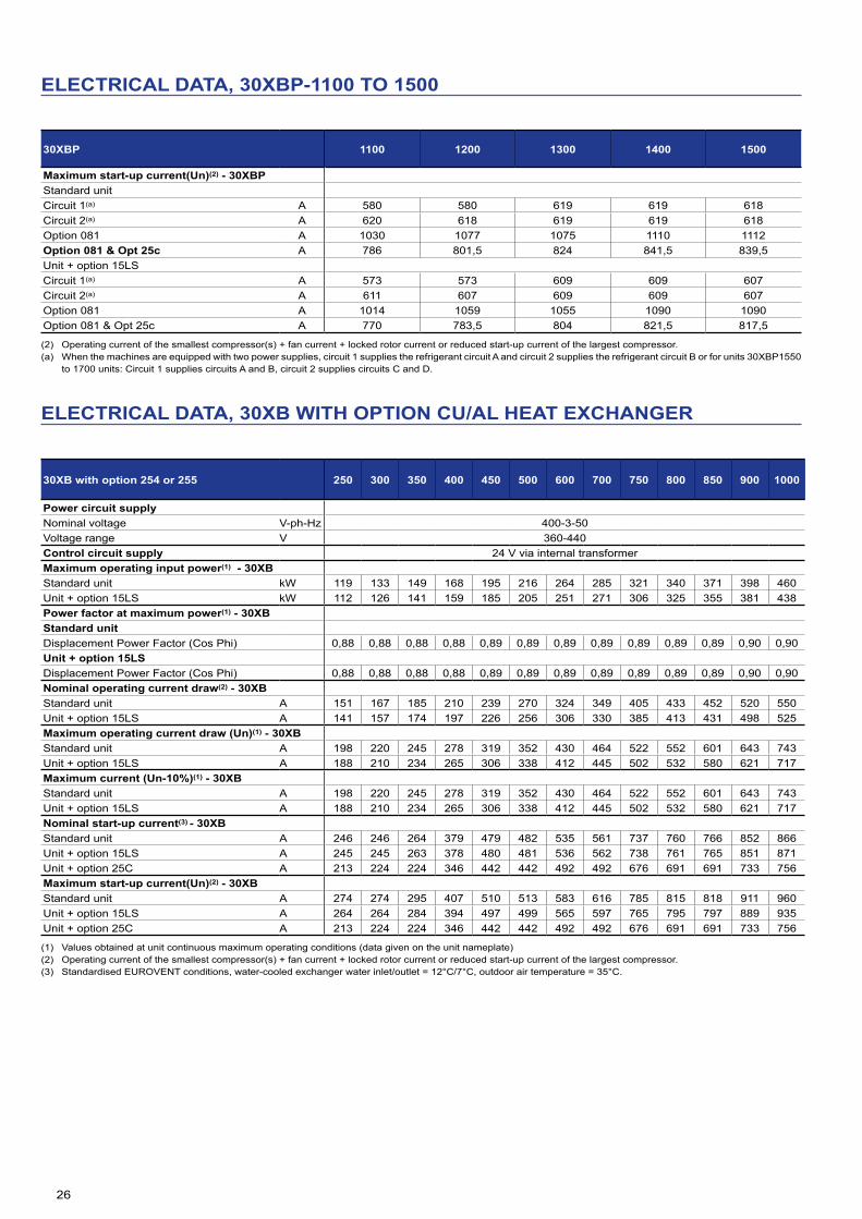
ELECTRICAL DATA, 30XBP-1100 TO 1500
30XBP 1100 1200 1300 1400 1500
Power circuit supplyNominal voltage V-ph-Hz 400-3-50Voltage range V 360-440 Control circuit supply 24 V via internal transformerMaximum operating input power(1) - 30XBPStandard unitCircuit 1(a) kW 154 164 201 211 230Circuit 2(a) kW 214 234 210 229 230Option 081 kW 368 397 411 439 460Unit + option 15LSCircuit 1(a) kW 145 157 193 200 219Circuit 2(a) kW 200 220 199 215 216Option 081 kW 348 380 397 419 439Power factor at maximum power(1) - 30XBPStandard unitDisplacement Power Factor (Cos Phi) 0,88 0,88 0,88 0,88 0,88Unit + option 15LSDisplacement Power Factor (Cos Phi) 0,86 0,87 0,87 0,86 0,86Nominal operating current draw(2) - 30XBPStandard unitCircuit 1(a) A 251 267 331 346 379Circuit 2(a) A 349 381 346 376 379Option 081 A 600 648 677 722 758Unit + option 15LSCircuit 1(a) A 244 260 321 336 368Circuit 2(a) A 335 363 330 360 361Option 081 A 584 630 657 702 736Maximum operating current draw (Un)(1) - 30XBPStandard unit Circuit 1(a) A 313 359 430 460 498Circuit 2(a) A 457 498 460 495 498Option 081 A 772 859 892 957 998Unit + option 15LSCircuit 1(a) A 306 352 420 450 487Circuit 2(a) A 448 487 450 485 487Option 081 A 584 630 657 702 736Maximum current (Un-10%)(1) - 30XBPStandard unit Circuit 1(a) A 313 359 430 460 498Circuit 2(a) A 457 498 460 495 498Option 081 A 772 859 892 957 998Unit + option 15LSCircuit 1(a) A 306 352 420 450 487Circuit 2(a) A 448 487 450 485 487Option 081 584 630 657 702 736Nominal start-up current(3) - 30XBPStandard unitCircuit 1(a) A 580 580 619 619 618Circuit 2(a) A 620 618 619 619 618Option 081 A 923 962 965 995 997Option 081 & Opt 25c A 786 801,5 824 841,5 839,5Unit + option 15LSCircuit 1(a) A 573 573 609 609 607Circuit 2(a) A 611 607 609 609 607Option 081 A 907 944 945 975 975Option 081 & Opt 25c A 770 783,5 804 821,5 817,5
(1) Values obtained at unit continuous maximum operating conditions (data given on the unit nameplate)(2) Operating current of the smallest compressor(s) + fan current + locked rotor current or reduced start-up current of the largest compressor.(3) Standardised EUROVENT conditions, water-cooled exchanger water inlet/outlet = 12°C/7°C, outdoor air temperature = 35°C.(a) When the machines are equipped with two power supplies, circuit 1 supplies the refrigerant circuit A and circuit 2 supplies the refrigerant circuit B or for units 30XBP1550
to 1700 units: Circuit 1 supplies circuits A and B, circuit 2 supplies circuits C and D.
26
ELECTRICAL DATA, 30XBP-1100 TO 1500
30XBP 1100 1200 1300 1400 1500
Maximum start-up current(Un)(2) - 30XBPStandard unitCircuit 1(a) A 580 580 619 619 618Circuit 2(a) A 620 618 619 619 618Option 081 A 1030 1077 1075 1110 1112Option 081 & Opt 25c A 786 801,5 824 841,5 839,5Unit + option 15LSCircuit 1(a) A 573 573 609 609 607Circuit 2(a) A 611 607 609 609 607Option 081 A 1014 1059 1055 1090 1090Option 081 & Opt 25c A 770 783,5 804 821,5 817,5
(2) Operating current of the smallest compressor(s) + fan current + locked rotor current or reduced start-up current of the largest compressor.(a) When the machines are equipped with two power supplies, circuit 1 supplies the refrigerant circuit A and circuit 2 supplies the refrigerant circuit B or for units 30XBP1550
to 1700 units: Circuit 1 supplies circuits A and B, circuit 2 supplies circuits C and D.
ELECTRICAL DATA, 30XB WITH OPTION CU/AL HEAT EXCHANGER
30XB with option 254 or 255 250 300 350 400 450 500 600 700 750 800 850 900 1000
Power circuit supplyNominal voltage V-ph-Hz 400-3-50Voltage range V 360-440 Control circuit supply 24 V via internal transformerMaximum operating input power(1) - 30XBStandard unit kW 119 133 149 168 195 216 264 285 321 340 371 398 460Unit + option 15LS kW 112 126 141 159 185 205 251 271 306 325 355 381 438Power factor at maximum power(1) - 30XBStandard unitDisplacement Power Factor (Cos Phi) 0,88 0,88 0,88 0,88 0,89 0,89 0,89 0,89 0,89 0,89 0,89 0,90 0,90Unit + option 15LSDisplacement Power Factor (Cos Phi) 0,88 0,88 0,88 0,88 0,89 0,89 0,89 0,89 0,89 0,89 0,89 0,90 0,90Nominal operating current draw(2) - 30XBStandard unit A 151 167 185 210 239 270 324 349 405 433 452 520 550Unit + option 15LS A 141 157 174 197 226 256 306 330 385 413 431 498 525Maximum operating current draw (Un)(1) - 30XBStandard unit A 198 220 245 278 319 352 430 464 522 552 601 643 743Unit + option 15LS A 188 210 234 265 306 338 412 445 502 532 580 621 717Maximum current (Un-10%)(1) - 30XBStandard unit A 198 220 245 278 319 352 430 464 522 552 601 643 743Unit + option 15LS A 188 210 234 265 306 338 412 445 502 532 580 621 717Nominal start-up current(3) - 30XBStandard unit A 246 246 264 379 479 482 535 561 737 760 766 852 866Unit + option 15LS A 245 245 263 378 480 481 536 562 738 761 765 851 871Unit + option 25C A 213 224 224 346 442 442 492 492 676 691 691 733 756Maximum start-up current(Un)(2) - 30XBStandard unit A 274 274 295 407 510 513 583 616 785 815 818 911 960Unit + option 15LS A 264 264 284 394 497 499 565 597 765 795 797 889 935Unit + option 25C A 213 224 224 346 442 442 492 492 676 691 691 733 756
(1) Values obtained at unit continuous maximum operating conditions (data given on the unit nameplate)(2) Operating current of the smallest compressor(s) + fan current + locked rotor current or reduced start-up current of the largest compressor.(3) Standardised EUROVENT conditions, water-cooled exchanger water inlet/outlet = 12°C/7°C, outdoor air temperature = 35°C.

27
ELECTRICAL DATA, 30XB WITH OPTION CU/AL HEAT EXCHANGER
30XB with option 254 or 255 1100 1200 1300 1400 1500 1550 1700
Power circuit supplyNominal voltage V-ph-Hz 400-3-50Voltage range V 360-440 Control circuit supply 24 V via internal transformerMaximum operating input power(1) - 30XBStandard unitCircuit 1(a) kW 200 225 267 286 309 459 366Circuit 2(a) kW 294 312 286 307 309 230 366Option 081 kW 488 537 553 593 619 689Unit + option 15LSCircuit 1(a) kW 190 220 258 276 299 451 354Circuit 2(a) kW 277 303 276 297 299 222 354Option 081 kW 467 524 534 574 598 666Power factor at maximum power(1) - 30XBStandard unitDisplacement Power Factor (Cos Phi) 0,88 0,88 0,88 0,88 0,88 0,89 0,89Unit + option 15LSDisplacement Power Factor (Cos Phi) 0,88 0,88 0,88 0,88 0,88 0,89 0,89Nominal operating current draw(2) - 30XBStandard unitCircuit 1(a) A 261 274 341 356 390 543 446Circuit 2(a) A 364 392 356 386 390 273 446Option 081 A 625 666 697 742 780 820Unit + option 15LSCircuit 1(a) A 247 265 325 340 372 530 427Circuit 2(a) A 344 376 340 370 372 260 427Option 081 A 590 641 665 710 745 782Maximum operating current draw (Un)(1) - 30XBStandard unit Circuit 1(a) A 323 366 440 470 509 740 593Circuit 2(a) A 472 509 470 505 509 370 593Option 081 A 787 877 912 977 1020 1113Unit + option 15LSCircuit 1(a) A 309 357 424 454 491 727 574Circuit 2(a) A 452 493 454 489 491 357 574Option 081 A 762 852 880 945 985 1074Maximum current (Un-10%)(1) - 30XBStandard unit Circuit 1(a) A 319 366 440 470 509 740 593Circuit 2(a) A 464 509 470 505 509 370 593Option 081 A 785 877 912 977 1020 1113Unit + option 15LSCircuit 1(a) A 309 357 424 454 491 727 574Circuit 2(a) A 452 493 454 489 491 357 574Option 081 A 762 850 880 945 985 1074Nominal start-up current(3) - 30XBStandard unitCircuit 1(a) A 590 587 629 629 629 954 812Circuit 2(a) A 635 629 629 629 629 477 812Option 081 A 949 986 985 1015 1019 1316Option 081 & Opt 25c A 811 820 844 862 862Unit + option 15LSCircuit 1(a) A 576 578 613 613 611 941 793Circuit 2(a) A 615 613 613 613 611 464 793Option 081 A 1020 1070 1063 1098 1099 1393Option 081 & Opt 25c A 776 795 812 830 826
(1) Values obtained at unit continuous maximum operating conditions (data given on the unit nameplate)(2) Operating current of the smallest compressor(s) + fan current + locked rotor current or reduced start-up current of the largest compressor. (3) Standardised EUROVENT conditions, water-cooled exchanger water inlet/outlet = 12°C/7°C, outdoor air temperature = 35°C. (a) When the machines are equipped with two power supplies, circuit 1 supplies the refrigerant circuit A and circuit 2 supplies the refrigerant circuit B or for units 30XB1550
to 1700 units: Circuit 1 supplies circuits A and B, circuit 2 supplies circuits C and D.

28
ELECTRICAL DATA, 30XB WITH OPTION CU/AL HEAT EXCHANGER
30XB with option 254 or 255 1100 1200 1300 1400 1500 1550 1700
Maximum start-up current(Un)(2) - 30XBStandard unitCircuit 1(a) A 590 590 629 629 629 954 812Circuit 2(a) A 635 632 629 629 629 477 812Option 081 A 1055 1101 1095 1130 1134 1431Option 081 & Opt 25c A 811 820 844 862 862Unit + option 15LSCircuit 1(a) A 576 578 613 613 611 941 793Circuit 2(a) A 615 613 613 613 611 464 793Option 081 A 1020 1070 1063 1098 1099 1393Option 081 & Opt 25c A 776 795 812 830 826
(2) Operating current of the smallest compressor(s) + fan current + locked rotor current or reduced start-up current of the largest compressor. (a) When the machines are equipped with two power supplies, circuit 1 supplies the refrigerant circuit A and circuit 2 supplies the refrigerant circuit B or for units 30XB1550
to 1700 units: Circuit 1 supplies circuits A and B, circuit 2 supplies circuits C and D.
ELECTRICAL DATA
Electrical data notes and operating conditions for 30XB units:
• 30XB&XBP 250 to 1000 units have a single power connection point; 30XB & XBP 1100 to 1700 units have two connection points.
• The control box includes the following standard features:- One general disconnect switch per circuit- Starter and motor protection devices for each compressor, the fan(s) and the
pump- Control devices
Field connections:• All connections to the system and the electrical installations must be in full
accordance with all applicable local codes.• The Carrier 30XB & 30XBP units are designed and built to ensure conformance
with these codes. The recommendations of European standard EN 60204-1 (corresponds to IEC 60204-1) (machine safety - electrical machine components - part 1: General regulations) are specifically taken into account, when designing the electrical equipment.
IMPORTANT:• Generally the recommendations of IEC 60364 are accepted as compliance with
the requirements of the installation regulations.• Conformance with EN 60204 is the best means of ensuring compliance with the
Machines Directive ˜ 1.5.1. Annex B of EN 60204-1 describes the electrical characteristics used for the
operation of the machines.
1. Environment* . Environment as classified in EN 60364 (corresponds to IEC 60364):- Outdoor installation*- Ambient temperature range: from -20°C to +55°C**- Altitude less than or equal to 2000 m (for hydraulic module, see paragraph
4.7 in the IOM)- Presence of hard solids, class AE3 (no significant dust present)* - Presence of corrosive and polluting substances, class AF1 (negligible)- Competence of persons: BA4 (Persons wise); 30XB &30XBP machines are
not intended to be installed in locations open to anyone, including people with disabilities and children.
2. Compatibility for low-frequency conducted disturbances according to IEC61000-2-2 and to class 2 levels per IEC61000-2-4 standard:- Power supply frequency variation : +-2Hz- Phase imbalance : 2%- Total Voltage Harmonic Distortion (THDV) : 8%”
3. The neutral (N) line must not be connected directly to the unit (if necessary use a transformer).
4. Overcurrent protection of the power supply conductors is not provided with the unit.
5. The factory.installed disconnect switch(es)/circuit breaker(s) is (are) of a type suitable for power interruption in accordance with EN 60947-3 (corresponds to IEC 60947-3).
6. The units are designed for simplified connection on TN(s) networks (IEC 60364). For IT networks provide a local earth and consult competent local organisations to complete the electrical installation. Units delivered with variable frequency drive(s) (options : 28, 17) are not compatible with IT network. 30XB units are designed to use for domestic / residential and industrial environments:
• Machines that are not equipped with variable frequency drive(s) are in accordance with the codes :- 61000-6-3: General standards - Standard emission for residential,
commercial and light industry.- 61000-6-2: General standards - Immunity for industrial environments.
• Machines that are equipped with variable frequency drive(s) (options : 28, 17) are in accordance with standard EN61800 - 3 electric power variable speed drives - art 3: EMC requirements and specific test methods for the following classifications:-- Use in the first and second environments***.- Category C2 applicable in the first environment, on stationary devices
designed to be installed and commissioned by a professional.
Warning: In a residential environment, this product may cause radio interference in which case additional mitigation measures could be required.
• Leakage currents: If protection by monitoring the leakage currents is necessary to ensure the safety of the installation, the presence of additional leakage currents introduced by the use of variable frequency drive(s) in the unit must be considered. In particular these protection devices shall be of reinforced immunity types and have a threshold not lower than 150 mA.
• Capacitors that are integrated as part of the option 231 can generate electrical disturbances in the installation the unit is connected to. Presence of these capacitors must be considered during the electrical study prior to the start-up.
NOTE: If particular aspects of an actual installation do not conform to the conditions described above, or if there are other conditions which should be considered, always contact your local Carrier representative.
* The required protection level for this class is IP43BW (according to reference document IEC 60529). All 30XB & XBP units are protected to IP44CW and fulfil this protection condition.
** The maximum ambiant temperature allowed for machines equipped with option 231 is +40°C

29
PART LOAD PERFORMANCE
ESEER (in accordance with EUROVENT)
The ESEER (European seasonal energy efficiency ratio) permits evaluation of the average energy efficiency at part load, based on four operating conditions defined by Eurovent. The ESEER is the average value of energy efficiency ratios (EER) at different operating conditions, weighted by the operating time.
ESEER(Europeanseasonalenergyefficiencyratio)
Load % Air temperature°C Energyefficiency Operating time %
100 35 EER1 375 30 EER2 3350 25 EER3 4125 20 EER4 23
ESEER = EER1 x 3% + EER2 x 33% + EER3 x 41% + EER4 x 23%
NOTE: Constant leaving water temperature 7°C.
SEER for comfort chillers (in accordance with EU ECODESIGN)
The SEER (Seasonal energy efficiency ratio) permits the evaluation of the average energy efficiency of comfort chillers, based on multiple operating conditions (load variation from 0% to 100%). From 1st January 2018, Tier 1 and from 1st January 2021, Tier 2, European member states will impose minimum SEER values to meet the requirements of Eco-design directive for ENER Lot 21 comfort cooling chillers. The Ecodesign Directive aims to minimize the environmental impact of energy-related products through consideration of their full lifecycle.
SEPR is the new metric forchillers in comfort coolingapplications.
73% of the time = chiller load ≤ 50%
73% OFTHE TIME
26% OFTHE TIME
1% OFTHE TIME
OutdoorTemperature (°C)
Uni
t loa
d (%
)
15°0
20
40
60
80
100
20° 25° 30° 35° 39°17°
EU ECODESIGN MEPS(*) for air-cooled chillers
Tier 1 (from 01/01/2018)
Tier 2 (from 01/01/2021)
SEER for comfort Chillers< 400kW
kWh/kWh
3,80 4,10
SEER for comfort Chillers> 400kW
kWh/kWh
4,10 4,55
(*) Minimum Efficiency Performance Standards set by EU member states to comply with EU Ecodesign directive.
SEPR for process chillers (in accordance with EU ECODESIGN)
The SEPR (Seasonal energy performance ratio) permits the evaluation of the average energy efficiency of process chillers, based on multiple operating conditions (load variation from 80% to 100%). From 1st January 2018, Tier 1 and from 1st January 2021, Tier 2, European member states will impose minimum SEPR values for process chillers to meet the requirements of Eco-design directive for ENER Lot 21 for high temperature process chillers (7°C to 12°C) and for ENTR Lot 1 for low temperature process chillers (-25°C to -8°C) and medium temperature process chillers ( -8°C to 7°C). The Ecodesign Directive aims to minimize the environmental impact of energy-related products through consideration of their full lifecycle. All process chillers marked with a CE label must meet the required SEPR (Seasonal Energy Performance Ratio) value stipulated in EU Directive.
SEPR is the new metric forchillers in industrial processcooling applications.
75% of the time = chiller operation < 17°C ambient
75% OFTHE TIME
24% OFTHE TIME
<1% OFTHE TIME
OutdoorTemperature (°C)
Uni
t loa
d (%
)
-20°0
20
40
60
80
100
-10° -0° 10° 17° 20° 30° 39°
EU ECODESIGN MEPS(*) for air-cooled chillers
Tier 1 (from 01/01/2018)
Tier 2 (from 01/01/2021)
SEPR for medium temperature Process Chillers < 300 kW
kWh/kWh
2,24 2,58
SEPR for medium temperature Process Chillers > 300 kW
kWh/kWh
2,80 3,22
EU ECODESIGN MEPS(*) for air-cooled chillers
Tier 1 (from 01/07/2016)
Tier 2 (from 01/07/2018)
SEPR for high temperature Process Chillers < 400 kW
kWh/kWh
4,50 5,00
SEPR for high temperature Process Chillers > 400 kW
kWh/kWh
5,00 5,50
(*) Minimum Efficiency Performance Standards set by EU member states to comply with EU Ecodesign directive.

30
SOUND SPECTRUM 30XB UNITS
30XB - Standard unit
Octave bands, Hz (1) Sound power level (2)125 250 500 1k 2k 4k
250 dB 96 95 92 98 86 81 dB(A) 99300 dB 96 95 92 98 86 81 dB(A) 99350 dB 97 95 92 98 86 81 dB(A) 99400 dB 97 96 94 98 88 83 dB(A) 99450 dB 104 106 95 96 88 84 dB(A) 101500 dB 96 95 95 96 91 86 dB(A) 99600 dB 103 105 96 95 90 86 dB(A) 101700 dB 97 95 95 96 91 86 dB(A) 99750 dB 104 107 97 99 90 86 dB(A) 103800 dB 100 101 98 100 92 88 dB(A) 103850 dB 99 98 97 97 91 88 dB(A) 101900 dB 100 103 98 102 91 87 dB(A) 1041000 dB 101 101 98 99 90 90 dB(A) 1021100 dB 101 103 100 99 94 88 dB(A) 1031200 dB 101 103 99 98 94 88 dB(A) 1021300 dB 102 103 102 101 94 88 dB(A) 1041400 dB 101 103 102 101 94 88 dB(A) 1041500 dB 101 103 102 101 94 88 dB(A) 1041550 dB 103 103 100 102 92 91 dB(A) 1041700 dB 102 101 100 100 94 91 dB(A) 104
(1) In dB ref=10-12 W, as a guideline. Measured in accordance with ISO 9614-1.(2) In dB ref=10-12 W, weighting (A), with uncertainty +/-3 dB. Measured in accordance
with ISO 9614-1 and certified by Eurovent.
30XB - Unit with Option 15LS
Octave bands, Hz (1) Sound power level (2)125 250 500 1k 2k 4k
250 dB 88 89 83 84 76 68 dB(A) 87300 dB 88 89 83 84 76 68 dB(A) 87350 dB 88 89 83 84 76 68 dB(A) 87400 dB 89 92 87 86 80 71 dB(A) 90450 dB 90 96 87 86 80 69 dB(A) 91500 dB 92 94 89 87 81 72 dB(A) 91600 dB 90 96 91 88 81 77 dB(A) 93700 dB 92 94 90 87 82 73 dB(A) 92750 dB 91 97 91 89 80 70 dB(A) 94800 dB 92 94 92 90 81 72 dB(A) 94850 dB 96 96 92 89 81 74 dB(A) 94900 dB 93 94 94 92 80 71 dB(A) 951000 dB 97 96 93 89 79 75 dB(A) 941100 dB 97 95 91 88 86 85 dB(A) 941200 dB 97 95 91 88 86 85 dB(A) 941300 dB 97 98 99 93 90 87 dB(A) 991400 dB 97 95 92 90 88 86 dB(A) 951500 dB 98 96 93 91 89 87 dB(A) 961550 dB 100 97 95 91 81 77 dB(A) 961700 dB 98 98 94 91 83 76 dB(A) 96
(1) In dB ref=10-12 W, as a guideline. Measured in accordance with ISO 9614-1.(2) In dB ref=10-12 W, weighting (A), with uncertainty +/-3 dB. Measured in accordance
with ISO 9614-1 and certified by Eurovent.
30XB - Unit with Option 15
Octave bands, Hz (1) Sound power level (2)125 250 500 1k 2k 4k
250 dB 95 94 90 90 83 78 dB(A) 93300 dB 95 94 90 90 83 78 dB(A) 93350 dB 95 94 91 90 83 78 dB(A) 94400 dB 96 95 92 91 85 80 dB(A) 95450 dB 96 94 92 91 86 80 dB(A) 95500 dB 96 94 93 91 86 81 dB(A) 95600 dB 96 97 94 93 89 82 dB(A) 97700 dB 97 95 94 92 86 81 dB(A) 96750 dB 101 99 94 94 86 81 dB(A) 97800 dB 98 96 95 95 87 82 dB(A) 98850 dB 99 96 95 94 87 83 dB(A) 97900 dB 99 97 95 96 87 82 dB(A) 991000 dB 99 96 95 94 87 83 dB(A) 981100 dB 101 98 95 91 90 87 dB(A) 981200 dB 101 98 95 91 90 87 dB(A) 981300 dB 102 99 99 95 92 88 dB(A) 1001400 dB 101 99 96 93 90 87 dB(A) 991500 dB 101 99 96 93 90 87 dB(A) 991550 dB 101 98 97 97 89 85 dB(A) 1001700 dB 102 99 98 97 90 86 dB(A) 100
(1) In dB ref=10-12 W, as a guideline. Measured in accordance with ISO 9614-1.(2) In dB ref=10-12 W, weighting (A), with uncertainty +/-3 dB. Measured in accordance
with ISO 9614-1 and certified by Eurovent.
30XB - Unit with Option 15LS+
Octave bands, Hz (1) Sound power level (2)125 250 500 1k 2k 4k
450 dB 89 93 84 85 76 67 dB(A) 89500 dB 90 92 85 85 77 70 dB(A) 89600 dB 91 93 88 87 79 77 dB(A) 91700 dB 92 92 87 85 79 73 dB(A) 90750 dB 92 94 89 87 79 73 dB(A) 91800 dB 93 92 90 88 80 75 dB(A) 92850 dB 93 92 90 87 79 74 dB(A) 91900 dB 94 92 91 89 80 76 dB(A) 931000 dB 94 91 91 87 79 75 dB(A) 921100 dB 97 93 90 87 85 84 dB(A) 931200 dB 97 93 90 87 85 84 dB(A) 931300 dB 95 96 97 91 88 85 dB(A) 971400 dB 97 95 91 88 86 85 dB(A) 941500 dB 98 96 92 89 87 86 dB(A) 951550 dB 95 93 93 89 80 76 dB(A) 931700 dB 95 94 92 89 81 76 dB(A) 93
(1) In dB ref=10-12 W, as a guideline. Measured in accordance with ISO 9614-1.(2) In dB ref=10-12 W, weighting (A), with uncertainty +/-3 dB. Measured in accordance
with ISO 9614-1 and certified by Eurovent.

31
SOUND SPECTRUM 30XBP UNITS
30XBP - Standard unit
Octave bands, Hz (1) Sound power level (2)125 250 500 1k 2k 4k
250 dB 96 95 92 98 86 81 dB(A) 99300 dB 96 95 92 98 86 81 dB(A) 99350 dB 97 95 92 98 86 81 dB(A) 99400 dB 97 96 94 98 88 83 dB(A) 99450 dB 104 106 95 96 88 84 dB(A) 101500 dB 96 95 95 96 91 86 dB(A) 99600 dB 103 105 96 95 90 86 dB(A) 101700 dB 97 95 95 96 91 86 dB(A) 99750 dB 104 107 97 99 90 86 dB(A) 103800 dB 100 101 98 100 92 88 dB(A) 103850 dB 99 98 97 97 91 88 dB(A) 101900 dB 100 103 98 102 91 87 dB(A) 1041000 dB 101 101 98 99 90 90 dB(A) 1021100 dB 101 103 100 99 94 88 dB(A) 1031200 dB 101 103 99 98 94 88 dB(A) 1021300 dB 102 103 102 101 94 88 dB(A) 1041400 dB 101 103 102 101 94 88 dB(A) 1041500 dB 101 103 102 101 94 88 dB(A) 104
(1) In dB ref=10-12 W, as a guideline. Measured in accordance with ISO 9614-1.(2) In dB ref=10-12 W, weighting (A), with uncertainty +/-3 dB. Measured in accordance
with ISO 9614-1 and certified by Eurovent.
30XBP - Unit with Option 15LS
Octave bands, Hz (1) Sound power level (2)125 250 500 1k 2k 4k
250 dB 88 89 83 84 76 68 dB(A) 87300 dB 88 89 83 84 76 68 dB(A) 87350 dB 88 89 83 84 76 68 dB(A) 87400 dB 89 92 87 86 80 71 dB(A) 90450 dB 90 96 87 86 80 69 dB(A) 91500 dB 92 94 89 87 81 72 dB(A) 91600 dB 90 96 91 88 81 77 dB(A) 93700 dB 92 94 90 87 82 73 dB(A) 92750 dB 91 97 91 89 80 70 dB(A) 94800 dB 92 94 92 90 81 72 dB(A) 94850 dB 96 96 92 89 81 74 dB(A) 94900 dB 93 94 94 92 80 71 dB(A) 951000 dB 97 96 93 89 79 75 dB(A) 941100 dB 97 95 91 88 86 85 dB(A) 941200 dB 97 95 91 88 86 85 dB(A) 941300 dB 97 98 99 93 90 87 dB(A) 991400 dB 97 95 92 90 88 86 dB(A) 951700 dB 98 96 93 91 89 87 dB(A) 96
(1) In dB ref=10-12 W, as a guideline. Measured in accordance with ISO 9614-1.(2) In dB ref=10-12 W, weighting (A), with uncertainty +/-3 dB. Measured in accordance
with ISO 9614-1 and certified by Eurovent.
30XBP - Unit with Option 15
Octave bands, Hz (1) Sound power level (2)125 250 500 1k 2k 4k
250 dB 95 94 90 90 83 78 dB(A) 93300 dB 95 94 90 90 83 78 dB(A) 93350 dB 95 94 91 90 83 78 dB(A) 94400 dB 96 95 92 91 85 80 dB(A) 95450 dB 96 94 92 91 86 80 dB(A) 95500 dB 96 94 93 91 86 81 dB(A) 95600 dB 96 97 94 93 89 82 dB(A) 97700 dB 97 95 94 92 86 81 dB(A) 96750 dB 101 99 94 94 86 81 dB(A) 97800 dB 98 96 95 95 87 82 dB(A) 98850 dB 99 96 95 94 87 83 dB(A) 97900 dB 99 97 95 96 87 82 dB(A) 991000 dB 99 96 95 94 87 83 dB(A) 981300 dB 101 98 95 91 90 87 dB(A) 981400 dB 101 98 95 91 90 87 dB(A) 981500 dB 102 99 99 95 92 88 dB(A) 1001550 dB 101 99 96 93 90 87 dB(A) 991700 dB 101 99 96 93 90 87 dB(A) 99
(1) In dB ref=10-12 W, as a guideline. Measured in accordance with ISO 9614-1.(2) In dB ref=10-12 W, weighting (A), with uncertainty +/-3 dB. Measured in accordance
with ISO 9614-1 and certified by Eurovent.

32
OPERATING LIMITS
Water heat exchanger Minimum Maximum
Entering temperature at start-up °C - 45(1)
Leaving temperature during operation °C 3,3 15Entering/leaving water temperature difference K 2,8 10
Condenser air temperature Minimum Maximum
Storage -20 68Operation, standard unit -10 55(2)
With winter operation option (option 28) -20 55(2)
With Low noise option (option 15LS) -10 55(2)
Note: If the air temperature is below 0°C, a glycol/water solution or the frost protection option must be used.
Note: If the leaving water temperature is below 4°C, a glycol/water solution or the frost protection option must be used.
(1) Based on the installation type and the air temperature(2) Part load, depended of sizes & leaving water temperature
Units without hydraulic module
30XB & 30XBP Minimum flowrate(1) (l/s)
Maximum flowrate(2) (l/s)
250 3,6 37,5300 4,0 40,5350 4,3 40,5400 5,3 34,1450 6,0 36,9500 6,7 42,0600 8,1 45,0700 8,9 56,1750 9,6 59,1800 10,4 67,1850 11,0 67,1900 11,8 73,91000 13,1 83,91100 15,1 87,81200 16,4 126,51300 17,5 92,91400 16,4 132,11500 18,8 107,41550 19,9 109,41700 22,0 107,4
(1) Minimum flow rate for maximum allowable water temperature difference conditions (10K) under Eurovent conditions
(2) Maximum flow rate for a pressure drop of 100 kPa in the exchanger
OPERATING RANGE
30XB/XBP Standard units
Evaporator leaving water temperature,°C
Air
ente
ring
tem
pera
ture
,°C
30XB/XBP with option 15LS or 15LS+
Evaporator leaving water temperature,°C
Air
ente
ring
tem
pera
ture
,°C
Legend
Operating range, unit equipped with option 28 (winter operation)
Below 0°C air temperature the unit must either be equipped with the evaporator frost protection option (41A or 41B), or the water loop must be protected against frost by using a frost protection solution (by the installer).
Part load average

33
DIMENSIONS / CLEARANCES
30XB250 to 350, 30XBP250 to 35030XB250 to 300 with option 254/255
30XB400 to 450, 30XBP400 to 50030XB350 to 400 with option 254/255
LegendAll dimensions are given in mm.
NOTES: - Drawings are not contractually binding. - Before designing an installation, consult the certified dimensional drawings, available on request.
- If the installation includes several units or if this (these) is (are) close to walls, please refer to chapters 3.13 - “Multiple chiller installation” and 3.14 - “Distance to the wall” of the installation manual to determine the space required.
Required clearances for maintenance (see note)
Recommended space for evaporator tube removal
Water inlet for standard unit - for options 5, 6, 100A, 100C, 107 refer to the certified drawing.
Water outlet for standard unit - for options 5, 6, 100A, 100C, 107 refer to the certified drawing.
Air outlet – do not obstruct
Power supply and control connection
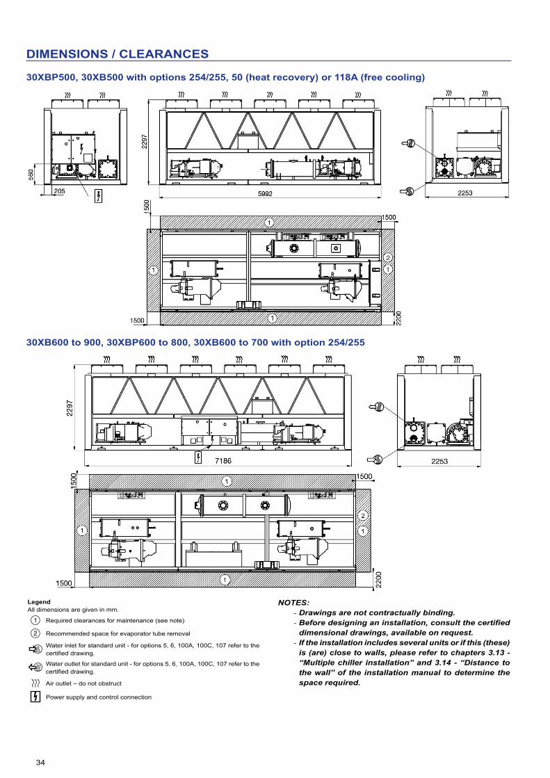
34
DIMENSIONS / CLEARANCES
30XBP500, 30XB500 with options 254/255, 50 (heat recovery) or 118A (free cooling)
30XB600 to 900, 30XBP600 to 800, 30XB600 to 700 with option 254/255
LegendAll dimensions are given in mm.
NOTES: - Drawings are not contractually binding. - Before designing an installation, consult the certified dimensional drawings, available on request.
- If the installation includes several units or if this (these) is (are) close to walls, please refer to chapters 3.13 - “Multiple chiller installation” and 3.14 - “Distance to the wall” of the installation manual to determine the space required.
Required clearances for maintenance (see note)
Recommended space for evaporator tube removal
Water inlet for standard unit - for options 5, 6, 100A, 100C, 107 refer to the certified drawing.
Water outlet for standard unit - for options 5, 6, 100A, 100C, 107 refer to the certified drawing.
Air outlet – do not obstruct
Power supply and control connection

35
DIMENSIONS / CLEARANCES
30XB1000, 30XBP850 to 900, 30XB750 to 850 with option 254/255
30XBP1000, 30XB900 option 254/255,30XB1000 with options 50 (heat recovery) & 118 (free cooling)
LegendAll dimensions are given in mm.
NOTES: - Drawings are not contractually binding. - Before designing an installation, consult the certified dimensional drawings, available on request.
- If the installation includes several units or if this (these) is (are) close to walls, please refer to chapters 3.13 - “Multiple chiller installation” and 3.14 - “Distance to the wall” of the installation manual to determine the space required.
Required clearances for maintenance (see note)
Recommended space for evaporator tube removal
Water inlet for standard unit - for options 5, 6, 100A, 100C, 107 refer to the certified drawing.
Water outlet for standard unit - for options 5, 6, 100A, 100C, 107 refer to the certified drawing.
Air outlet – do not obstruct
Power supply and control connection

36
DIMENSIONS / CLEARANCES
30XB1100 to 1400, 30XBP1100 to 1400
2253419
419x
1500
22001500
1500
1
1
1
21
3
467
2297
467
30XB1500, 30XBP1500
LegendAll dimensions are given in mm.
NOTES: - Drawings are not contractually binding. - Before designing an installation, consult the certified dimensional drawings, available on request.
- If the installation includes several units or if this (these) is (are) close to walls, please refer to chapters 3.13 - “Multiple chiller installation” and 3.14 - “Distance to the wall” of the installation manual to determine the space required.
Required clearances for maintenance (see note)
Recommended space for evaporator tube removal
Water inlet for standard unit - for options 5, 6, 100A, 100C, 107 refer to the certified drawing.
Water outlet for standard unit - for options 5, 6, 100A, 100C, 107 refer to the certified drawing.
Air outlet – do not obstruct
Power supply and control connection
30XA1114 : X = 957430XA1214 : X = 1077030XA1112, 1212, 1312, 1382 : X = 11962

37
DIMENSIONS / CLEARANCES
30XB1550 module 1/2
Mod
ule
2
To the water inlet of module 2
30XB1550 module 2/2
Module 1
Water inlet (to be connected to the water outlet of module 1)
LegendAll dimensions are given in mm.
NOTES: - Drawings are not contractually binding. - Before designing an installation, consult the certified dimensional drawings, available on request.
- If the installation includes several units or if this (these) is (are) close to walls, please refer to chapters 3.13 - “Multiple chiller installation” and 3.14 - “Distance to the wall” of the installation manual to determine the space required.
Required clearances for maintenance (see note)
Recommended space for evaporator tube removal
Water inlet for standard unit - for options 5, 6, 100A, 100C, 107 refer to the certified drawing.
Water outlet for standard unit - for options 5, 6, 100A, 100C, 107 refer to the certified drawing.
Air outlet – do not obstruct
Power supply and control connection

38
DIMENSIONS / CLEARANCES
30XB1700 module 1/2M
odul
e 2
To the water inlet of module 2
30XB1700 module 2/2
Module 1
Water inlet (to be connected to the water outlet of module 1)
LegendAll dimensions are given in mm.
NOTES: - Drawings are not contractually binding. - Before designing an installation, consult the certified dimensional drawings, available on request.
- If the installation includes several units or if this (these) is (are) close to walls, please refer to chapters 3.13 - “Multiple chiller installation” and 3.14 - “Distance to the wall” of the installation manual to determine the space required.
Required clearances for maintenance (see note)
Recommended space for evaporator tube removal
Water inlet for standard unit - for options 5, 6, 100A, 100C, 107 refer to the certified drawing.
Water outlet for standard unit - for options 5, 6, 100A, 100C, 107 refer to the certified drawing.
Air outlet – do not obstruct
Power supply and control connection

39
SPECIFICATION GUIDE
General description
Factory assembled single piece air-cooled chiller, shall include all factory wiring, piping, controls, refrigerant charge (R134a), completely independent refrigerant circuits, screw compressors, electronic expansion valves and equipment required prior to field start-up.
The unit performance shall be certified by Eurovent or AHRI independent testing laboratory.
The unit shall operate at full load up with ambient temperatures ranging from -20°C to 48°C without tripping and without the use of additional adiabatic systems.
Quality assurance
Unit shall be rated in accordance with EN14511, EN14825 and AHRI 550/590 standards, latest revisions, and unit performance shall be certified by independent certification body.
- Unit without independent Eurovent or AHRI certification shall be excluded.
- Unit construction shall comply with European directives: - From 1st January 2018, commission regulation (EU) N°2016/2281 implementing Directive 2009/125/EC with regards to Eco-design requirements for comfort cooling chillers and process chillers.
- Commission regulation (EU) N°640/2009 implementing Directive 2009/125/EC with regards to Eco-design requirements for electrical motors
- From 1st January 2015, commission regulation (EU) N°547/2012 implementing Directive 2009/125/EC with regards to Eco-design requirements for water pumps (unit equipped with hydraulic module option)
- Pressurised equipment directive (PED) 2014/68/UE - Machinery directive 2006/42/EC, modified - Low voltage directive 2014/35/UE - Electromagnetic compatibility directive 2014/30/UE, modified, and the applicable recommendations of European standards
- Machine safety: electrical equipment in machines, general requirements, EN 60204-1
- Electromagnetic compatibility emission EN61000-6-4 - Electromagnetic compatibility immunity EN61000-6-2 - Directive 2009/125/EC with regard to ecodesign requirements for fans driven by motors with an electric input power between 125 W and 500 kW
- Directive 2005/32/EC with regard to ecodesign requirements for electric motors
- (if pumps on board) Directive 2009/125/EC with regard to ecodesign requirements for water pumps
Unit shall be designed, manufactured and tested in a facility with a quality management system certified ISO 9001 and environmental management system ISO 14001.
Unit shall be run tested at the factory.
Design performance data following European EN14825 & EN14511 standards
- Cooling capacity (kW): …… - Unit power input (kW): …… - Part load energy efficiency, SEER (kW/kW): …… - Part-load energy efficiency, SEPR (kW/kW): ....... - Full load energy efficiency, EER (kW/kW): …… - Eurovent Class ……… - Evaporator entering/leaving water temperature (°C): … / - Fluid type: ……. - Fluid flow rate (l/s): …… - Evaporator pressure drops (kPa): …… - Outdoor air temperature (°C): …… - Sound power level at full load (dB(A)): …… - Dimensions, length x depth x height (mm): … x … x
Performance shall be declared in accordance either with EN14511-3:2013 and certified by Eurovent or with AHRI 550/590 standard and certified by AHRI.
The unit shall operate at full load with ambient temperatures ranging from -10°C to 48°C without use of additional adiabatic cooler systems, with evaporator leaving liquid temperature between 3.3°C and 7°C. When evaporator leaving water temperature is higher than 7°C, up to 15°C, the maximum outdoor air temperature may be lower to secure machine safe operation. The machine shall continue to operate (at reduced capacity) in ambient temperatures of up to 55°C, with evaporator leaving liquid temperature between 3.3°C and 10°C.
- (Carrier option 5) Chilled brine solution production down to -10°C when ethylene glycol is used, or down to -6°C when propylene glycol is used.
- (Carrier option 6) Chilled brine solution production down to -15°C when ethylene glycol is used, or down to -10°C when propylene glycol is used.
- (Carrier option 28 or 17) The unit shall operate at full load down to -20°C ambient air temperature.
Frame
- Machine frame and enclosure shall be made of galvanised sheet steel
- Frame and enclosure shall be painted in oven-baked polyester powder paint in light grey colour (RAL 7035)
- Removable panels and electrical panel doors shall be accessible by 1/4-turn screws
- (Carrier option 23) Machine shall be protected from foreign bodies through the use of metal grilles factory-mounted on the four vertical faces. Coils refrigerant connections shall be covered by side panels of galvanised sheet steel, for enhanced aesthetic and safety during transportation.
- (Carrier option 23A) Coils refrigerant connections shall be covered by side panels of galvanised sheet steel, for enhancead aesthetic and safety during transportation.

40
SPECIFICATION GUIDE
Compressor
- Unit shall have semi-hermetic twin-screw compressors with internal relief valve and check valve to avoid reverse rotation on shut down
- Unit shall be equipped with a muffler to reduce discharge gas pulsations
- Compressor bearings shall be designed for minimum 73000 hours at maximum operating conditions
- Capacity control shall be provided by a slide valve - Compressor capacity control shall be stepless from 100% to 30% load
- Compressor shall start in unloaded condition - Motor shall be cooled by suction gas and protected by a dedicated electronic board against:
- Thermal overload by internal winding temperature sensors - Electrical overload and short circuit by dedicated fuses (one per phase)
- Reverse rotation - Loss of phase - Undervoltage and power supply failure. - Lubrication oil system shall include pre-filter and external filter capable of filtration to 5 microns
- The oil filter line shall be equipped with service shut off valves for easy filter replacement
- The oil separator, separate from the compressor, shall not require oil pump and shall include an internal muffler to reduce discharge gas pulsations
- The oil separator shall be designed for 2100 kPa working pressure
- The oil separator shall include a temperature actuated heater and an oil level safety switch
- Compressors shall be installed on flexible anti-vibration mounts and isolated from the main unit chassis
- (Carrier opton 93A) Each compressor shall be equipped with a discharge shut-off valve
- (Carrier option 279A) Each compressor and oil separator shall be installed within an enclosure with removable panels to facilitate service access
- (Carrier option 15 or 15LS) Each compressor shall be installed within an insulated acoustic enclosure with removable panels to facilitate service access.
Evaporator
- Unit shall be equipped with a single flooded evaporator - Evaporator shall be manufactured by the chiller manufacturer - Evaporator shall be tested and stamped in accordance with the European directive for pressurised equipment 2014/68/UE
- The maximum refrigerant-side operating pressure will be 2100 kPa, and the maximum waterside pressure will be 1000 kPa (2100kPa as an option)
- The evaporator shall be mechanically cleanable, shell-and-tube type with removable heads
- Tubes shall be internally and externally grooved, seamless-copper, and shall be rolled into tube sheets
- Shell shall be insulated with 19 mm closed-cell foam with a maximum K factor of 0.28. Evaporator thermal insulation shall be factory fitted
- The evaporator shall have a drain and vent in each head - Chiller shall have only one water inlet & outlet connection with Victaulic couplings to avoid vibrations transmission and to accommodate minor pipework misalignment (Victaulic adapter kit shall be available on demand)
- Design shall incorporate 2 independent refrigerant circuits
- Evaporator shall be fitted with electronic auto setting water flow switch. Paddle switches or differential pressure switches shall not be acceptable
- (Carrier option 281) Unit shall be fitted with a cooler jacket to protect the insulation from the long-term effects of UV radiation.
Condenser
- Condenser coils shall be designed to ensure sub-cooling of the liquid refrigerant
- Condenser coils shall be V-shaped with a minimum open angle of 50° to ensure optimum air distribution
- Coils shall be entirely made of aluminium alloy, micro-channels type.
- Coils shall consist of a two-pass arrangement - Coils shall be leak-tested at 15.5 bar with 100% He - (Carrier options 254/255) Coils shall use copper tubes and aluminium fins
- (Carrier option 262) Coils shall be suitable for installations in moderately corrosive environment. The protection shall consist on a nano-scale conversion coating, 100 to 200 nm thick, which uniformly covers the entire surface of the coil. Non conversion coating shall not be accepted. The coating process shall include immersion in a coating bath. The coating shall be applied by an autocatalytic conversion process which shall modify the surface of the aluminum producing a coating that is integral to the coil. Complete immersion shall ensure that 100% of the surface is coated, forming a continuous and even film. Spray coating process shall not be accepted. The coating shall be integral to the NovationTM MCHE and shall not flake or loose adhesion with cross hatch adhesion of 5B per ASTM D3359. The thin coating shall have no effect on heat transfer or air flow per ARI 410. The coating shall utilise corrosion inhibitors which actively arrest damage due to environmental or mechanical damage. Corrosion durability of coated microchannel coils shall be confirmed through testing to no less than 5000 hours constant neutral salt spray per ASTM B117.
- (Carrier option 263) Coils shall be suitable for installations in the most severe environments. The protection shall consist of a flexible epoxy polymer coating uniformly applied to all coil external surface areas without material bridging between fins. The coating shall be applied by an electrocoating process with immersion in a coating bath and a final UV protective topcoat to shield the fins from ultraviolet degradation and to ensure coating durability and long life. Spray coating and non-electrocoating shall not be accepted. Coating process shall ensure complete coil encapsulation, including all exposed fin edges. The coating shall have a uniform thickness of 20 to 40 μm on all external coil surface areas including fin edges. The coating shall have minimal effect (<1%) on heat transfer or air flow per ARI 410. The coating shall have superior hardness characteristics of 2H per ASTM D3363 and cross hatch adhesion of 4B-5B per ASTM D3359. Impact resistance shall be up to 100 in/lb (ASTM D2794). Corrosion durability of coated microchannel coils shall be confirmed through testing to no less than 5000 hours constant neutral salt spray per ASTM B117.

41
SPECIFICATION GUIDE
Fans
- (30XB standard unit) Fans shall be fixed-speed AC fans - (30XB with option 17) Fans shall be variable-speed AC fans with one or more variable-speed drives per refrigerant circuit.
- (30XBP premium unit) Fans shall be EC fans. - Fans shall be direct-drive, equipped with an impeller with 9 aerodynamic blades and a rotating shroud to ensure optimal leak-tightness between the blades and the fan housing
- Fans impellers shall be of one-piece and made of a corrosion-resistant composite material, and statically and dynamically balanced
- The fans discharges shall be protected by polyethylene-coated steel wire grilles
- The three-phase electric motors shall have isolation class F, IP 55 protection and a minimum efficiency of 80%. They shall have individual overload protection via a disconnect switch
- (Carrier option 10) Fans shall be equipped with discharge connection flanges increasing available discharge pressure up to 60 kPa
- Noise levels shall be adjustable electronically per time band on user display to guarantee a quiet operation during night or building unoccupied periods.
Refrigerant circuit
- Refrigerant circuit components shall include: compressor, oil separator, high and low side pressure relief devices, economiser, filter driers, moisture indicating sight glasses, long stroke electronic expansion device, and complete operating charge of both refrigerant R134a and compressor oil
- (Carrier option 92) For each refrigerant circuit, a compressor suction and discharge line shut off valve, an evaporator inlet valve and economiser line valve, shall be mounted to isolate all main components (filter drier, oil filter, expansion device and compressor) and allow refrigerant to be safely stored during service operation
- (Carrier opton 93A) Each compressor shall be equipped with a discharge shut-off valve
- (Carrier option 257) Compressor and oil separator sub-assembly and refrigerant gas suction line shall be acoustically insulated
- (Carrier option 258) Compressor and oil separator sub-assembly, refrigerant gas suction line and the economiser subassembly (if needed) shall be acoustically insulated.
Power control boxes
- Unit shall operate at 400 Volts (+/- 10%), 3-phases, 50 Hertz power supply without neutral
- Unit shall be designed for simplified connection on TN(s) networks
- Unit shall have maximum holding short circuit current of 38000 Amps up to 500 kW, of 50000 Amps up to 1000 kW and 100000 Amps up to 1700 kW nominal cooling capacity
- Control circuit voltage shall be 24 V maximum, supplied by a factory-installed transformer
- Unit shall be supplied with factory-installed main circuit breaker/isolator
- Unit shall have a factory installed star/delta starter as standard to limit electrical inrush current
- Power control box is powder painted with hinged and gasket sealed doors and is protected to IP44CW
- (Carrier option 20A) The power control box shall be protected to IP54 to permit safe operation for installations in polluted environment
- (Carrier option 70D) The main electrical disconnect switch shall integrate fuses for protection against over current flow
- (Carrier option 81 for sizes 1102/1502, standard for all other sizes)Unit shall have single point power connection
- (Carrier option QM231) The unit shall include capacitors to ensure a power factor of 0.95 at full load.
Controls
- Unit control shall include as a minimum: microprocessor with non-volatile memory, picture guided unit/operator interface, the LOCAL/OFF/REMOTE/CCN selector and a 5 inch coloured touch-screen display with 10 languages capability: German, English, Spanish, French, Italian, Dutch, Portuguese, Turkish, Russian and one additional language on customer choice (downloadable on job site)
- (Carrier option 158A) Unit control shall include as a minimum: microprocessor with non-volatile memory, picture guided unit/operator interface, the LOCAL/OFF/REMOTE/CCN selector and a 7 inch coloured touch-screen display with multiple language capability
- Pressure sensors shall be installed to measure suction, discharge, and oil pressure
- Temperature probes shall be installed to read cooler entering and leaving temperatures and outdoor air temperature
- Unit control shall have an IP port to permit user connection via web browser, allowing same level of access to control menus as unit mounted interface (excluding start/stop and alarm reset capabilities)
- Control shall store technical documentation, drawings and spare parts list specific to each particular unit
- (Carrier option 148B) A bi-directional communication board shall allows plug and play interfacing of the machine with any BMS using the J-Bus protocol
- (Carrier option 148D) A bi-directional communication board shall allows plug and play interfacing of the machine with any BMS using the LonTalk protocol
- (Carrier option 149) Machine shall be supplied with factory installed bi-directional high-speed communication using BACnet protocol over Ethernet network (IP-connection). The BACnet over-IP communication shall have no limitation in reading/writing controller points and shall use standardised alarm codes as defined with BACnet protocol. Field programming shall be required
- (Carrier option 298) Machine shall be accessible via wireless connection for remote monitoring to facilitate to preventive maintenance.
Unit shall be capable of performing the following functions: - Electronic expansion valve control optimising evaporator refrigerant charge while ensuring minimum refrigerant supeheat and optimum subcooling at condenser outlet
- Capacity control based on leaving chilled fluid temperature - Limitation of the chilled fluid-temperature pull-down rate at start-up to an adjustable range of 0.1°C to 1.1°C per minute to prevent excessive demand spikes at start-up
- Automatic change-over and cycling of compressors to equalise running hours and number of starts
- Reset enable of leaving chilled-water temperature based on the outdoor air temperature or via 0-10 V signal (as option)
- Dual set point management for the leaving chilled water temperature activated by a remote contact closure signal or by the built in time clock
- 2-level demand limit control (between 0 and 100%) activated by remote contact closure or by the built in time clock

42
SPECIFICATION GUIDE
- Time schedule management to enable unit start-up control, demand limit and set-point changes
- Trending of main variables (accessible by web browser only) - (Carrier option 58) lead/lag type control of two chillers running in series or parallel
- (Carrier option 116) Evaporator pump control, including additional standby pump (if installed)
- (Carrier opton 156) The following inputs contacts shall be available on the unit control board:
- Setpoint reset by indoor air temperature sensor - Cooling setpoint reset by 4-20 mA - Time schedule override - Ice storage input - Demand limit - Unit shut down
The following outputs contacts shall be available on the unit control board:
- Instantaneous chiller capacity by 0-10 V signal - Complete shut-down due to a chiller fault - Compressor operation indication.
Diagnosis
- Control interface shall be capable of displaying set points, system status including temperatures, pressures, current for each compressor, run time and percent loading
- Control interface shall perform trending of up to 10 preselected variables
- Control system shall allow a quick test of all machine elements to verify the correct operation of every switch, circuit breaker, contactor etc. before the chiller is started
- In case of alarm, control system shall send an email to specific mail box set by user during machine commissioning
- Control shall have a black box function capable of storing a data set of 20 variables, at intervals of 5 seconds, for 14 minutes preceding the alarm and 1 minute after the alarm. The black box shall be able to record 20 events. Once this threshold is reached, new data shall over-write the oldest record.
Refrigerant leak alert:
The liquid chiller shall be equipped as standard with an automatic refrigerant leak detection algorithm:
- Indicates serious refrigerant loss from any point in the system. - Sensitivity: 25% refrigerant charge loss per circuit (depending on the conditions).
- Refrigerant leak detection (option 159): - Available as an option, an additional dry-contact shall allow reporting of possible leaks. The leak detector (by others) should be mounted in the most likely leak location.
Safeties
Control system shall provide the unit with protection against the following:
- Reverse rotation - Low chilled water temperature - Low oil pressure (per compressor) - Current imbalance - Compressor thermal overload - High pressure (with automatic compressor unloading in case of excessive condensing temperature)
- Electrical overload and short circuit - Loss of phase, undervoltage and power supply failure - Control shall provide separate general alert (minor incident) and alarm (circuit down) remote indication.
Hydraulic module (optional)
(Carrier 30XB and 30XBP 250 to 500 option 116B/C/F/G) A choice of different pump types and configurations shall be available:
- Single high-pressure pump - Dual high-pressure pumps - Single low-pressure pump - Dual low-pressure pumps
If dual pumps are fitted, the unit control shall automatically manage the change-over and cycling of pumps to equalise running hours and number of starts
The hydraulic module shall be integrated in the chiller chassis without increasing its dimensions
The hydraulic module shall include the following elements:
- Removable screen filter - Centrifugal monocell water pump with three-phase motor equipped with internal over-temperature protection
- Electronic water flow switch without paddle - Relief valve calibrated to 4 bar - Long stroke flow control valve - Pressure gauge and valve set for differential pressure measurement
- The water pump shall be isolated from the chiller structure and water piping by anti-vibration mountings and expansion compensators, in order to limit vibration and noise trasmission
- The water piping shall be protected against corrosion and equipped with drain and purge plugs
- The hydraulic connections shall be Victaulic type - Both pump and piping shall be fully insulated with polyurethane foam clad with aluminum to prevent condensation
- (Carrier option 41B) Pump frost protection shall be guaranteed down to -20°C by electric resistance heaters
- Piping frost protection shall be guaranteed down to -20°C by automatic pump activation when liquid temperature falls below a safety limit
Total heat recovery (optional)
(Carrier option 50) The unit shall include an additional heat exchanger in parallel with the condenser coils to recover 100% of condenser heat
Dx Free-cooling (optional)
(Carrier option 118A) The unit shall include one additional refrigerant pump on each refrigerant circuit to provide partial free-cooling during the cold season. The free-cooling option shall not require the addition of glycol to the water loop.


Order No.: 10204, 11.2017. Supersedes order No.: 10204, 09.2017. Manufactured by: Carrier SCS, Montluel, France.Manufacturer reserves the right to change any product specifications without notice. Printed in the European Union.