303 Elsevier HIGHER-ORDER THEORIES FOR SYMMETRIC AND
18
Finite Elements in Analysis and Design 6 (1990) 303-320 303 Elsevier HIGHER-ORDER THEORIES FOR SYMMETRIC AND UNSYMMETRIC FIBER REINFORCED COMPOSITE BEAMS WITH C O FINITE ELEMENTS T. KANT * and B.S. MANJUNATHA Department of Cioil Engineering Indian Institute of Technology, Powai, Bombay-400 076, India Received June 1989 Revised January 1990 Abstract. A simple Co isoparametric finite element formulation based on a set of higher-order displacement models for the analysis of symmetricand asymmetricmultilayered composite and sandwich beams subjected to sinusoidal loading is presented. These theories do not require the usual shear correction coefficients which are generally associated with the Timoshenko theory. The four-noded Lagrangian cubic element with kinematic models having four, five and six degrees of freedom per node is used. A computer algorithm is developed which incorporates realistic prediction of transverse interlaminar stresses from equilibrium equations. By comparing the results obtained with the elasticity solution and the CPT (classical laminated plate theory) it is shown that the present higher-order theories give a much better approximation to the behaviour of laminated composite beams, both thick and thin. In addition numerical results for unsymmetric sandwich beams are presented which may serve as benchmark for future investigations. Introduction Laminated composite structures offer the advantages of high strength-to-weight ratio and the possibility of optimum design through the variation of fiber orientation, stacking pattern and choice of fiber and matrix material. They evidence the behaviour of isotropic, orthotropic or anisotropic materials depending upon the particular configuration. But the presence of free edges in composite structures often gives rise to a complex three-dimensional stress field with steep gradients. This phenomenon has been studied both experimentally and analytically to a considerable depth during the last two decades. It is believed that delamination occurring near the free edges is due to the steep interlaminar stress gradients in the free edge region. However, much controversy still exists regarding the nature and magnitude of the interlaminar free edge stresses. Thus, in this paper an attempt has been made to evaluate accurately the interlaminar stresses in composite and sandwich beams. Analysis of a beam in the past has been done by many investigators using the theories of Euler-BernouUi [12] and Timoshenko [10]. In case of deep beams with low l/h ratios where shear effects can not be neglected Euler-Bernoulli theory leads to serious discrepancies. Further, it is computationally inefficient from the point of view of simple finite element formulations. Timoshenko [10] improved this theory by incorporating effects of transverse shear strain into the governing equation system. The resulting transverse shear distribution was constant through the beam thickness and thus a shear correction coefficient, which is somewhat arbitrary, was introduced to correct the strain energy of deformation. Many investigators have worked on Timoshenko's theory [1,5,6] and some of them have given new expressions for shear correction * To whom all communicationsshould be addressed. 0168-874X/90/$3.50 © 1990 - Elsevier Science Publishers B.V.
Transcript of 303 Elsevier HIGHER-ORDER THEORIES FOR SYMMETRIC AND
Finite Elements in Analysis and Design 6 (1990) 303-320 303 Elsevier
HIGHER-ORDER THEORIES FOR SYMMETRIC AND U N S Y M M E T R I C FIBER REINFORCED C O M P O S I T E BEAMS W I T H C O FINITE E L E M E N T S
T. KANT * and B.S. M A N J U N A T H A
Department of Cioil Engineering Indian Institute of Technology, Powai, Bombay-400 076, India
Received June 1989 Revised January 1990
Abstract. A simple C o isoparametric finite element formulation based on a set of higher-order displacement models for the analysis of symmetric and asymmetric multilayered composite and sandwich beams subjected to sinusoidal loading is presented. These theories do not require the usual shear correction coefficients which are generally associated with the Timoshenko theory. The four-noded Lagrangian cubic element with kinematic models having four, five and six degrees of freedom per node is used. A computer algorithm is developed which incorporates realistic prediction of transverse interlaminar stresses from equilibrium equations. By comparing the results obtained with the elasticity solution and the CPT (classical laminated plate theory) it is shown that the present higher-order theories give a much better approximation to the behaviour of laminated composite beams, both thick and thin. In addition numerical results for unsymmetric sandwich beams are presented which may serve as benchmark for future investigations.
Introduction
Laminated composite structures offer the advantages of high strength-to-weight ratio and the possibility of optimum design through the variation of fiber orientation, stacking pattern and choice of fiber and matrix material. They evidence the behaviour of isotropic, orthotropic or anisotropic materials depending upon the particular configuration. But the presence of free edges in composite structures often gives rise to a complex three-dimensional stress field with steep gradients. This phenomenon has been studied both experimentally and analytically to a considerable depth during the last two decades. It is believed that delamination occurring near the free edges is due to the steep interlaminar stress gradients in the free edge region. However, much controversy still exists regarding the nature and magnitude of the interlaminar free edge stresses. Thus, in this paper an attempt has been made to evaluate accurately the interlaminar stresses in composite and sandwich beams.
Analysis of a beam in the past has been done by many investigators using the theories of Euler-BernouUi [12] and Timoshenko [10]. In case of deep beams with low l / h ratios where shear effects can not be neglected Euler-Bernoulli theory leads to serious discrepancies. Further, it is computationally inefficient from the point of view of simple finite element formulations.
Timoshenko [10] improved this theory by incorporating effects of transverse shear strain into the governing equation system. The resulting transverse shear distribution was constant through the beam thickness and thus a shear correction coefficient, which is somewhat arbitrary, was introduced to correct the strain energy of deformation. Many investigators have worked on Timoshenko's theory [1,5,6] and some of them have given new expressions for shear correction
* To whom all communications should be addressed.
0168-874X/90/$3.50 © 1990 - Elsevier Science Publishers B.V.

3 0 4 T. Kant, B.S. Manjunatha / Fiber reinforced composite beams
coefficients for different cross-sections of the beam. But in the case of composite beams, the discrepancy between the results of Timoshenko's theory and the elasticity theory is seen to be large, even after refining the values of shear coefficients.
A second-order beam theory similar to Timoshenko's beam theory has been given by Stephen and Levinson [9]. This theory, however, contains two coefficients, one of which depends on cross-sectional warping, while the other, although similar in form, also includes terms dependent on the transverse direct stress. Levinson [3,4] has developed a new fourth-order beam theory, which requires two boundary conditions at each end of the beam. Here, transverse shear deformation and cross-sectional warping are taken into account and thus, shear correction coefficients are not used. This displacement hypothesis, however, is too poor to adequately describe the two-dimensional displacement pattern. Rychter [8] has improved the consistency and accuracy of Levinson's theory by imbedding in it the two-dimensional linear theory of elasticity.
The main aim of the present work is to develop refined theories which can accurately evaluate the interlaminar stresses by using C O finite element discretization. These theories include all the secondary effects such as transverse shear stress, transverse shear stain, transverse normal stress and strain and their variation across the beam thickness [2].
Theory and formulations
A set of theoretical models are developed based on the following kinematic assumptions. These are designated as hOST1, hOST2, etc. (see Fig. 1)
VERTICAL
d w o
dx \
W O
. . . . . . . . . . . . LE PLANE
%(x)
I
Fig. 1. Laminate geometry with positive set of lamina/laminate reference axes and displacement components.

T. Kant, B.S. Manjunatha / Fiber reinforced composite beams 305
HOSTI
, ( x , z) = Uo(X) + , ¢ ( x ) ,
w(x, 2) = Wo(~) + 2Oz(~), (1)
HOST2
u(x, 2) = Uo(X) + ~¢(~) + :uS(~) , w(~ , 2) = Wo(X) + 2 o , ( : ) . (2)
HOSt3
u(x, 2) = Uo(X) + 2 ¢ 0 , ) + : o r ( x ) ,
w(x, ~) -- Wo(~) + ~ ¢ ( x ) , (3)
HOST4
u(x , z) = Uo(X ) + ZOx(X ) + : u ~ ' ( x ) + :Ox*(X),
w(x, z) = Wo(X ) + zOz(x ). (4)
where the parameters u and w define the displacements of any point (x, z) in the beam domain in the x- and z-directions respectively. The parameters u0, w0, Ox, Oz, u~' and 0* are the appropriate one-dimensional terms in the Taylor series and are defined along the x-axis at Z ~ 0 .
Here only derivations for HOST4 are presented. Other theoretical models become special cases of HOST4. The variations in the case of HOST1, 2 and 3 are given concisely in the Appendix. By substituting eqn. (4) into the strain-displacement relations of three-dimensional elasticity [11], the following relations are obtained:
3 . ~'x -~ ~'xO + ZKx + Z2Cx*O + Z K x ,
£z = CzO,
~,xz = ~, + 2,,,,z + z%*, (5)
where,
. . [OUo aOx Ou3' OO~* ] [~xO, Kx, CxO, K x , q O ] = Ox' Ox' Ox ' Ox'Oz ,
[ ~w0 OOz ] [~, rxz, ~* ] = 0x + --~-, 2u~ + -~ - , 30* , (6)
Each lamina in the laminate is assumed to be in a two-dimensional state of stress, so that the constitutive relation for a typical lamina L can be written as
"r~z GJD%J where
El vI2E2 E2 = , C12 = , C22 = , (8)
C l l 1 - v12v12 1 - - P121,,12 1 - - lt12P12
and o x, o z, %z are the stress and Cx, %, Yxz are the strain components referred to the lamina/laminate coordinates (x-z).

=
in which,
306 T. Kant, B.S. Manjunatha /Fiber reinforced composite beams
The total potential energy H of the beam can be written as,
I I = ½ fz~T6 d x - - f f f Tpo dx ,
in which
6 = [N x, N,, Nx*, M x, M : , Q, Q*, S] T,
= [~xO' CzO' ExO' ICx' ICx' qJ' ~*' ICxz] T'
. T a = [Uo, Wo, oz, u¢, o; ] , . T
Po = [ P~o, P,o, mxo, m,o, P*o, mxo ] •
The stress-resultants in eqn. (10) are defined as follows:
N~ 0 0 = ~+' o~ [1, Z, g z, g 3] dz.
Qx S Q* L=I Txz]
After integration, these stress-resultants are written in matrix form as follows:
8 = D ~ ,
where the form of the matrix D is, [> os],
/)MB =
C l l h l C12hl
NL C22hl
symm. L=I
Cllh3
C12h 3
Cllh5
Cllh2 C11h 4 "
C12h2 C12h4
Cnh4 Cllho ,
Cllh3 Cllh5
Cllh7
(9)
(10)
(11)
(12)
(13)
(14)
Ghl Gh3 Gh21 NL
Ds = E Oh.I , (15) l
L=I symm. Gh3J
, i (16) h i = l / i (hL+ 1 - h L ) , i = 1 , 2 . . . . . 7.
The interlaminar shear and normal stresses (rx,, az) cannot be accurately estimated by eqn. (7). This is mainly due to the fact that these stresses have to maintain continuity across the interfaces whereas constitutive laws are discontinuous. The three/two-dimensional analysis becomes very complex due to thickness variation of constitutive laws and continuity require- ments across the interface. Thus, the interlaminar shear and normal stresses for any layer L at z is obtained by integrating the two equilibrium equations of two-dimensional elasticity for each layer over the lamina thickness and summing over layers 1 to L as follows.
The equations of equilibrium representing the point wise equilibrium can be written as,
rij,j = O, i, j = X, Z. (17)
Substituting the lamina stresses in eqn. (17) and integrating, the following expression for

T. Kant, B.S. Manjunatha / Fiber reinforced composite beams 307
interlaminar shear stress is obtained.
L fh,+, 8o~ I+=,,L+, = - E j,,, - f f dz + c, . (18)
i=1
A second-order differential equation is obtained for interlaminar normal stress in terms of in-plane stress after eliminating the interlaminar shear stress from eqn. (17).
02o+ :Ox aZ 2 aX 2 . (19)
The following equation is obtained for interlaminar normal stress after integrating eqn. (19) twice,
'+ : ,+ , ( fO Ox ) o?[+=h++, = ,=rE Sh, ~Jz~x 2 dz d z + z C 2 + C3. (20)
Thus, it is seen that interlaminar stresses can be obtained by using stress equilibrium equations. For calculating in-plane stresses and stains, displacement-based finite dement models can be used. In this manner stresses in the laminate can be evaluated. However, in eqn. (18) for interlaminar shear stress, it is seen that the values obtained may not in general satisfy beam boundary conditions at z = + h/2, as only one constant of integration is present.
This problem does not arise in the case of o z, as here two constants of integration, obtained by integrating twice, can be determined by substituting two boundary conditions at + = + h/2. Equation (18) is substituted in the second equilibrium equation to get the continuity of oz across the thickness. Equation (20) is solved as a boundary value problem instead of an initial value problem as in eqn. (18). However, this requires the use of at least a cubic element, so that the third derivative of displacements can be determined. For this reason, a four-noded cubic element is used here in the numerical study.
Finite element formulation
We follow the standard finite element technique, in which the total solution domain 13 is subdivided into NE sub-domains (elements) 131, 132 . . . . . 13t,+E such that,
NE
/ - / (d) = Y'. H e ( d ) , (21) e ~ l
in which H and/- /e are the total potential energies of the system and the element, respectively. We further express
l'~e(d) ~- U e - W e, (22)
where U e and W e are the internal strain energy and the external work done, respectively, for the element e. In C O finite element theory, the continuum displacement vector within the element is discretized such that
NN
d = ~_, N t ( x ) d i, (23) i ~ l
where N/(x) is the interpolating function associated with node i, N N is the number of nodes in an element and di is the generalized displacement vector corresponding to the i th node of an element.
308 T. Kant, B.S. Manjunatha / Fiber reinforced composite beams
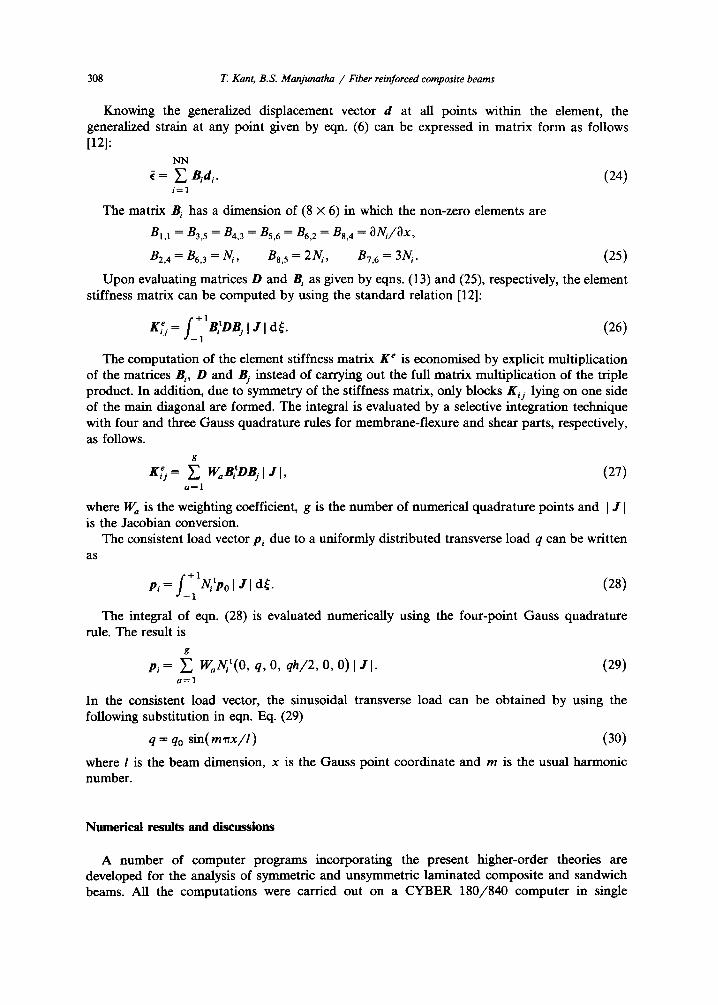
Knowing the generalized displacement vector d at all points within the element, the generalized strain at any point given by eqn. (6) can be expressed in matrix form as follows [12]:
NN
i = E Bidi. (24) i=1
The matrix B i has a dimension of (8 × 6) in which the non-zero elements are
B1,1 = B3, 5 = B4, 3 = Bs, 6 = B6, 2 = B8, 4 = ~Ni/ax ,
B2, 4 = Br. 3 -- N/, ns, 5 -- 2N/, n7, 6 = 3N/. (25)
Upon evaluating matrices D and Bi as given by eqns. (13) and (25), respectively, the element stiffness matrix can be computed by using the standard relation [12]:
e f + l t KiJ = "]-1 BiDBjl J I d~. (26)
The computation of the dement stiffness matrix K e is economised by explicit multiplication of the matrices B~, D and Bj instead of carrying out the full matrix multiplication of the triple product. In addition, due to symmetry of the stiffness matrix, only blocks Kij lying on one side of the main diagonal are formed. The integral is evaluated by a selective integration technique with four and three Gauss quadrature rules for membrane-flexure and shear parts, respectively, as follows.
g
K~j = ~ WaBtDBjl J I, (27) a = l
where W a is the weighting coefficient, g is the number of numerical quadrature points and I J I is the Jacobian conversion.
The consistent load vector p~ due to a uniformly distributed transverse load q can be written as
r + l t Pi = ' ]_ 1 N / P 0 1 J ] d~. ( 2 8 )
The integral of eqn. (28) is evaluated numerically using the four-point Gauss quadrature rule. The result is
g
P, = E W,N~t( 0, q, O, qh/2 , 0, 0) I J I- (29) a = l
In the consistent load vector, the sinusoidal transverse load can be obtained by using the following substitution in eqn. Eq. (29)
q = qo s in(mqrx/ l ) (30)
where l is the beam dimension, x is the Gauss point coordinate and m is the usual harmonic number.
Numerical results and discussions
A number of computer programs incorporating the present higher-order theories are developed for the analysis of symmetric and unsymmetric laminated composite and sandwich beams. All the computations were carried out on a CYBER 180/840 computer in single
T. Kant, B.S. Manjunatha / Fiber reinforced composite beams 309
precision with a word length of 16 significant digits. The following material properties have been considered to simulate a high modulus graphite/epoxy composite:
Ett = 25 × 10 6 psi,
Gtt = 0.50 × 10⁶ psi,
Boundary conditions:
E t -- 1 × 10⁶ psi,
tit = 0.25.
Wo = 0z = 0, at x = 0 and 1, (31)
where l signifies the direction parallel to the fibers, t is the transverse direction and vtt is the Poission's ratio measuring the strain in the transverse direction under uniaxial normal stress in the l direction.
The following three problems are considered for the comparison of displacements and stresses with the elasticity and CPT (classical laminated plate theory) solutions [7]. (1) An orthotropic beam with fibers oriented in the x-direction. (2) An orthotropic coupled laminate with the t and l directions aligned parallel to x in the top
and bottom layers respectively, the layers being of equal thickness. (3) A symmetric three-ply orthotropic beam with the ! direction coinciding with x in the outer
layers while t is parallel to x in the central layer, the layers being of equal thickness. A shear correction coefficient of 1.2 is used for HOST1, since it does not contain the
higher-order terms. The following non-dimensionalised quantities are used in connection with Figs. 2-5,
ox(l/2, z) oz(l/2, z) ~'xz(O, z) ~x , ~ , ~xz = , q q q
Etu(0, z) lOOEthaw(l/2, 0) (32) hq ' q l 4
Figures 2(a), 3(a) and 4(a) show the relationship between maximum deflection w 0 and l/h for the problems considered. The present theories slightly underestimate the values compared to elasticity solutions for lower values of l/h for Case 2 and Case 3. As expected for higher values of l/h all theories give the same values. The CPT underestimates the deflection and gives very poor estimates for relatively low values of l/h. The variation of in-plane stress through the beam thickness is shown in Figs. 2(b), 3(b) and 4(b) for l/h = 4. hOST3 and hOST4 estimate values very close to the elasticity solution compared to models hOST1 and rIOST2, with the latter group following the path of CPT. Next the variation of the same for l/h = 10 is shown in Figs. 2(d) and 4(d) for Case 1 and Case 2. Here also the results of HOST3 and HOST4 are close to elasticity solution compared to HOST1 and hOST2, with difference in results reducing considerably.
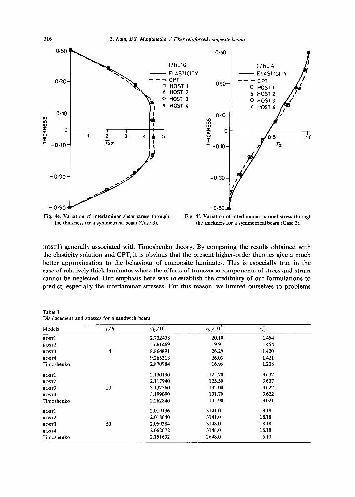
The distribution of rx~ through the beam thickness is shown in Figs. 2(c), 3(c) and 4(c) for the Cases 1, 2 and 3, respectively, for l/h = 4. Here the results of rIOST3 and HOST4 match well with the elasticity solution compared to hOST1 and HOST2. But the difference in the results with the elasticity solution is more significant in Case 3. Hence, in Fig. 4(e) the distribution of the same for l/h = 10 is shown. Here also the results of hOST3 and hOST4 are close to the elasticity solution compared to HOST1 and HOST1.
The variation of o~ along the beam thickness is shown in Figs. 3(d) and 4(d) for Case 2 and Case 3 for l/h = 4. The results of the present theories follow the same path as that of the elasticity solution. The CPT overestimates the values and follows a different path.
Next, a simply supported unsymmetric sandwich beam under sinusoidal loading is consid- ered. The following material properties are used.

310 T. Kant, B.S. Manjunatha / Fiber reinforced composite beams
2"0-
1 " 5 - -
z
G I "0-
LI. LU a
0 ' 5 -
ELASTICITY - - - - - - CPT
In HOST 1 A HOST 2 o HOST 3 X HOST 4
-- - - - - ~ - -- - - - ,d
0 I I 1 I I 0 10 2 0 30 4 0 S0
l l h RATIO
Fig. 2a, Variation of displacement w 0 with the l /h ratio for a unidirectional beam (Case 1).
0"S0-
0-30-
0-10-
I I
0 5
TY
/ - / - - ~, HOST 2 / / o HOST 3
~/1~ x HOST 4
INPLANE STRESS 0.10
-0-30
--0..50
Fig. 2b. Variation of in-plane stress through the thickness for a unidirectional beam (Case 1).

T. Kant, B.S. Manjunatha / Fiber reinforced composite beams 311
0"504
0.30-
o~ 0 . 1 0 -
Z ~" 0 U
-0.10-
-0.30-
-0.50~
l / h = 4 ELASTICITY
- - - C P T - , , ~ , ~ n HOST 1
" ~ R ~ ' ~ ~ HOST 2 "~ ~ o HOST 3
" ~ , X t'IOST/."
'
Fig. 2c. Variation of interlaminar shear stress through the thickness for a unidirectional beam (Case 1).
to /~ - - - - ELASTICITY " - - C P T
z O HOST 1
~ HOST 2 T P' 0.10- O HOST 3
)C HOST 4
'-6b -3's ~ lb 3'5 6'o INPLANE STRESS
-0"10
-0.30]
-0.50
Fig. 2d. Variation of inplane stress through the thickness for unidirectional beam (Case 1).

312 T. Kant, B.S. Manjunatha / Fiber reinforced composite beams
411 o~i ELASTICITY 4- ~ - - - - CPT
D HOST I a HOST 2 o HOST 3 x HOST 4
"~o 3.5-
z
tJ
3.0-
• . . . . i --- - -.i-
2.5-
2-0 I I i I I
0 10 20 30 40 50 llh RATIO
Fig. 3a. Variation of displacement w 0 with the l /h ratio for an unsymmetrical beam (Case 2).
I I I -30 -20 -I0
INPLANE STRESS
0 . 5 0 -
U')
0.30- U m "1" I--
0 ' 1 0 - -
[ /h :Z. ELASTICITY
- - -CPT O HOST 1 a H OST 2 o HOST 3 x HOST /-,
10
.0 4 0 / / ~ / / ~ o , "
-0.30
o ~ a -0.50
7 30
Fig. 3b. Variation of in-plane stress through the thickness for an unsymmetrical beam (Case 2).

T. Kant, B.S. Manjunatha / Fiber reinforced composite beams 313
0" 5 0 ~
030- I
0,10- t/') u') LI.I z 0
-r
- 0.10 -
l l h : 4 -ELASTICITY
---- --CPT O HOST 1 A HOST 2 o HOST 3 x HOST 4
~ 2 " 0 31.0
-0-50-I Fig. 3c. Variation of interlaminar shear stress through
the thickness for an unsymmetrical beam (Case 2).
0.50-
0.30-
m 0.I0- i , i z "" 0 .I- I - -
- 0 . 1 0 -
-0 .30-
- 0 - 5 0 -
l l h = 4
E L A S T I C I T Y - - - - C P T
n HOST 1
6 HOST 2
o HOST 3
x HOST 4
o15 / '7 1 1"0
Fig. 3d. Variation of interlarninar normal stress through the thickness for an unsymmetrical beam (Case 2).
Stiff layers:
E 1 = E 2 = 107 psi,
h core
hstiff b 3.75,
Core below the mid plane:
G = 5 x 1 0 3 psi,
Core above the mid plane:
G = 3 × 10⁴ psi,
E 1 G ~ _ . m
2(1 + ~ ) '
h Core - - - - 2 . 5 . h stifft
v = 0.30,
~,=0, E = 2 G .
v = 0 , E = 2 G .
The results for displacement, in-plane stress and interlaminar shear stress for different l / h ratios are given in Table 1. The variations of u, "rxz, o x and oz along the beam thickness are shown in Figs. 5(a), 5(b), 5(c) and 5(d) for l / h = 4. Large differences in displacement and stresses are obtained for hosT4 compared to HOST1, 2, 3 and Timoshenko theory for thick beams ( l / h <<. 4). The results almost converge to the latter group for relatively thin sandwich beams ( l / h >~ 50).
C o n c l u s i o n s
A simple C O isoparametric formulation of a set of higher-order theories (HOST2, HOST3 and HOST4) for the analysis of composite and sandwich beams subjected to sinusoidal loading is presented. These theories do not require the usual shear correction coefficients (except for

314 T. Kant, B.S. Manjunatha / Fiber reinforced composite beams
2.5-
2-0-
° 0
z 1 . 5 - 9 I, ,-
w ._1 1.1. w ,", 1.0-
0-5-
! ELASTICITY
- - - - - C P T
[] HOST 1 A HOST 2
o HOST 3
x HOST 4
I I I I I
0 10 20 30 40 50 I/h, RATIO
Fig. 4a. Variation of displacement w 0 with the l /h ratio for a symmetrical beam (Case 3).
I I I -20 -15 -10
0.S0~ i i
/ L - " - - - - " I . . . . C P T
J [ / [] H O S T 1
o,o~ x ~ o ; - - ' o .os; I
_~ 1o ~ , 1~ 2'o _1_o,o .,P'ANE STRESS
/ /
/ P ~ -0-30
/o-~~// - -0.50 Fig. 4b. Variation of inplane stress through the thickness for a symmetrical beam (Case 3).

T. Kant, B.S. Manjunatha /Fiber reinforced composite beams 315
O.lO- t n i , i z =c 0 U "t" p -
- 0 . 1 0 -
0"50 I \ , ,~lx ~ ~ l/h = 4
ELASTICITY
0.30~ ,,~T-- ~ CPT HOST 1 HOST 2
/ ~ o HOST 3 HOST 4
I
-0-30-
- 0-50
I I
0.5 1"0 Txz
/
I ®~ I
i I ,.s~ 2'.o
I
I
/
r
Fig. 4c. Variation of interlaminar shear stress through the thickness for a symmetrical beam (Case 3).
I
- 6 0
0 - 5 0 -
U3 U3
0.30- U
I ,- .
0"10
1 I I
-60 -40 -20 -0.10,
,,y - 0.30-
, , ~" - 0 . 5 o _
/ |/h =10 ELASTICITY
/ / CPT / ~ / HOST 1 [3
A HOST 2 0 HOST 3 x HOST 4
I I i i
20 40 60 ~0 INPLANE STRESS
Fig. 4d. Variation of in-plane stress through the thickness for symmetrical beam (Case 3).
3 1 6
0.504
0.30-
0.10- f f ) t/3 hi z 0 .w, u 1- ~" -0 .10-
- 0 " 3 0 -
T. Kant, B.S. Manjunatha / Fiber reinforced composite beams
l /h=10
ELASTICITY - - - - - C P T
O HOST 1 tx HOST 2
O HOST 3 Ill I HOST 4 x
I
I I I 1 2 3
~z
I I 4 J.
I
-0.50
Fig. 4e. Variation of interlaminar shear stress through the thickness for a symmetrical beam (Case 3).
0 " 5 0 -
0"30 -
0"10--
z 0 u m -r P - 0 . 1 0 -
-0.30-
-0.50~
llh=4 ~I ELASTICITY / "
- - - - - C P T / / El HOST 1 /~/~1 t
HOST 2 / / o HOST 3 ~ / X H O S T / n u
/ , ~ s 1 .0 o- z
/ Fig. 4f. Variation of interlaminar normal stress through
the thickness for a symmetrical beam (Case 3).
hOST1) generally associated with Timoshenko theory. By comparing the results obtained with the elasticity solution and CPT, it is obvious that the present higher-order theories give a much better approximation to the behaviour of composite laminates. This is especially true in the case of relatively thick laminates where the effects of transverse components of stress and strain cannot be neglected. Our emphasis here was to establish the credibility of our formulations to predict, especially the interlaminar stresses. For this reason, we limited ourselves to problems
Table 1 Displacement and stresses for a sandwich beam
Models I/h ~0/10 6x/103 qxez
HOST1 2.732438 20.10 HOST2 2.661469 19.91 HOST3 4 8.864891 26.29 HOST4 9.265313 26.03 Timoshenko 2.870984 16.95
HOST1 2.130190 125.70 HOST2 2.117940 125.50 HOST3 10 3.132560 132.00 HOST4 3.199090 131.70 Timoshenko 2.262840 105.90
HOST1 2.019136 3141.0 HOST2 2.018640 3141.0 HOST3 50 2.059384 3148.0 HOST4 2.062072 3148.0 Timoshenko 2.151632 2648.0
1.454 1.454 1.420 1.421 1.208
3.637 3.637 3.622 3.622 3.021
18.18 18.18 18.18 18.18 15.10

T. Kant, B.S. Manjunatha / Fiber reinforced composite beams 317
~ x ° 10.5 I/h = 10 o
o HOST 1 \ ~ z 6 HOST 2
"~ x \ \ 0"3 ~ HOST 3 HOST 4
\ \ A x -- -- -- TIMOS
\ \ ~ mO.1
, , , , / / ~ ~o, , l
-,. -3 -2 -~ I " I \ ~ 2 3 -0.1[ ~ \ \ 4 13 'u" DISPLACEMENT
\xl ',:° _o.3N~ \ 6 o
- 0.5-J ~ tax Fig. 5a. Variation of in-plane displacement through the thickness for a sandwich beam.
-0,5-
0.3. t/) IM z
..t- i-
0,1
i -1 I 0
-0,1
i I I
~z I I I I ! I t i
/ p
\ I Ih =10 o HOST 1 A HOST 2 l
I x HOST 3 ! ,, HOST 4 I ----- TIMOS I I I
!
2
_ 0.5-j~ v Fig. 5b. Variation of interlaminar shear stress through the thickness for a sandwich beam.
for which elasticity solutions are available. The numerical estimates of the interlaminar normal stress, which is of paramount importance in the delamination studies, was not available todate. This was due to the problem of high-order numerical differentiation in the longitudinal direction associated with the integration of the elasticity equilibrium equations. The use of

318 T. Kant, B.S. Manjunatha /Fiber reinforced composite beams
U~ bJ Z
( J
"1- I--
o
0"30-1 1/h =10 O HOST 1 A HOST 2 X HOST 3
HOST 4 0"10 . . . . TIMOS
r I i -30 -20 -I0
-0-10-
-0.30-
- o . s o
I I 1
10 20 30 INPLANE STRESS
Fig. 5c. Variation of inplane stress through the thickness for a sandwich beam.
0-5-
..z"' ~ 0"3- ~
_u / / "1- I -
0.1-- / /
/ r ~ , , l
-0-25 0.2 0.75 1.25 - D . I ~ Z
I l l h . 4 8
/ o HOST 1 / ~ HOST 2 /
/ x HOST 3 HOST 4
- - - - TIMOS
"'I _0.5~t~
Fig. 5d. Variation of interlaminar normal stress through the thickness for a sandwich beam.
cubic element seems to have given fairly accurate estimates of these stresses. While the discussion here is limited to a particular type of loading and bounda ry conditions, these theories can be used to deal with any type of loading and bounda ry conditions.

T. Kant, B.S. Manjunatha / Fiber reinforced composite beams 319
The results obtained from HOST1 and HOST3 follow close to the results of HOST2 and HOST4 respectively, with the results of HOST3 matching well with the elasticity solution for symmetric composite and sandwich beams. This is due to the fact that the inplane deformation of the reference axis becomes negligible for symmetric laminates under transverse loading pattern. Thus HOST3 can be used to tackle the symmetric composite and sandwich beams.
In unsymmetric case, the results of HOST4 match well with the elasticity solution, as the inplane displacement and its higher-order terms also play a paramount role in the analysis. Thus, this model should be used to tackle unsymmetric composite and sandwich beams.
Acknowledgement
Partial support of this research by the Aeronautics Research and Development Board, Ministry of Defence, Government of India through its Grants Aero/RD-134/100/84-85/362, Aero/RD-134/100/10/88-89/518 and 534 is gratefully acknowledged.
References
[1] COWPER, G.R., "The shear co-efficient in Timoshenko beam theory", ASME J. Appl. Mech. 33, pp. 335-340, 1966.
[2] KANT, T. and A. GUPTA, "A finite element model for a higher-order shear-deformable beam theory", J. Sound Vib. 125(2), pp. 193-202, 1988.
[3] LEVINSON, M., "A new rectangular beam theory", J. Sound Vib. 74, pp. 81-87, 1981. [4] LEVINSON, M., "On Bickford's consistent higher-order beam theory", Mech. Res. Commun. 12(1), pp. 1-9, 1985. [5] MURTY, A.V.K., "Vibration of short beams", AIAA J. 8(1), pp. 34-38, 1970. [6] MURTY, A.V.K., "Analysis of short beams", AIAA J. 8(11), pp. 2098-2100, 1970. [7] PAGANO, N.J., "Exact solution for composite laminates in cylindrical bending", J. Compos. Mater. 3, pp. 398-410,
1969. [8] RYCHTER, Z., "On the accuracy of a beam theory", Mech. Res. Commun. 14(2), pp. 99 -105, 1987. [9] STEPHEN, N.G. and M. LEVINSON, "m second order beam theory", J. Sound Vib. 67, pp. 293-305, 1979.
[10] TIMOSHENKO, S.P., "On the correction for shear in differential equation for transverse vibrations of prismatic bars", Philos. Mag. Ser. 6, 41, pp. 744-746, 1921.
[11] TIMOSHENKO, S.P. and J.N. GOODIER, Theory of Elasticity, McGraw-Hill, New York, 3rd edn., 1982. [12] ZIENKIEWlCZ, O.C. and R.L. TAYLOR, The Finite Element Method, Vol. 1, McGraw-Hill, Singapore, 4th edn., 1989.
Appendix
HOSTI
a = (u0, w, ¢ , ¢)t.
The membrane-f lexure and coupling matrix can be written as follows:
NL [ C l l h l C12hl C l l h 2 ]
C22hl C12h 1, L=I s y m m . Cllh 3 J
The D s matrix can be written as follows:
NL [ Ghl Gh2 ]
D s = L=IE LGh2 G h 3 j '
(A.1)
(A.2)
(A.3)

320 T. Kant, B.S. Manjunatha / Fiber reinforced composite beams
The non-zero dements of matrix B i (5 x 4) can be written as follows:
B1,1 --- B3, 3 --- B4, 2 = Bs, 4 -- ONi/Ox ,
B~,~ = B~,~ = U / . (A.4)
HOST2
d = ( u o, w o , 0 x, O z, u ~ ) t . (A.5)
The membrane-flexure and coupling matrix of dimension (4 × 4) is equal to the first (4 × 4) matrix in HOST4 of the membrane-flexure and coupling matrix.
The D s matrix is equal to the D s matrix of HOST4. The Bi matrix has dimension (6 × 5) in which the non-zero elements are,
n l , 1 = B3, 5 = B4, 3 = Bs, z = B6, 4 = aN/ / /~x ,
Bz, 4 = Bs, 3 = N/, B6, 5 = 2N/. (A.6)
HOST3
d = ( u o, w, Ox, Oz, O* )t . (A.7)
The membrane-flexure and coupling matrix can be written as follows:
I Cllhl Cazha C l l h 2 C l l h 4 ]
NL C22hl C12h2 C12h4 /
s y m m , C11h3 C'lh5 /" ( A . 8 ) L = I
C l l h 7 J
The D s matrix is equal to the D s matrix of HOST4. The non-zero elements of B i (7 × 5) can be written as follows:
Ba, 1 = B3, 3 = B4, 5 = Bs, 2 = B7, 4 = ~Ni/Ox ,
BE, 4 = B,, 3 = Ni, B6, 5 = 3N~. (A.9)