30004479 GA Qiona GB 2011-04 D
38
Qiona ® Ablation irrigation pump Operating instructions GB
Transcript of 30004479 GA Qiona GB 2011-04 D

Qiona® Ablation irrigation pump
Operating instructions
GB


Qiona®
Table of Contents
Page 3 of 38
Table of Contents General safety instructions Explanation of safety symbols used .............................................................................. 5 Manufacturer's liability .................................................................................................. 7 Operator's obligations ................................................................................................... 7 Additional accessories .................................................................................................. 8 Equipotential cable ....................................................................................................... 8 Single-use .................................................................................................................... 8 Statement regarding DEHP and BPA ........................................................................... 8
Purpose Indications for cooled ablation ...................................................................................... 9 Contraindications ........................................................................................................ 10 Complications ............................................................................................................. 10 Combination with other products ................................................................................ 11 Patient population & residual risk ................................................................................ 11
Product description Key pad and display layout ......................................................................................... 12 Connection options on the rear side ........................................................................... 12
Installation and startup Transport and storage instructions ............................................................................. 13 Unpacking the device and inspecting delivery ............................................................ 13 Startup ........................................................................................................................ 13
Application and operation Overview of primary operating functions ..................................................................... 14 1 Unpacking and connecting the Qiona® ..................................................................... 15 2 Turn on the Qiona® .................................................................................................. 15 3 Pre-setting and Setup .............................................................................................. 15 4 Open front panel ...................................................................................................... 18 5 Unpack the Qiona® Tube Set incl. Extension ........................................................... 18 6 Insert the Qiona® Tube ............................................................................................ 18 7 Close front panel ..................................................................................................... 19 8 Connect infusion container or infusion bottle ........................................................... 19 9 Remove the Qiona® Extension................................................................................. 19 10 Connect ablation catheter ...................................................................................... 19 11 Perform rinsing ...................................................................................................... 20 12 Start application ..................................................................................................... 20 Switch-over options .................................................................................................. 22 Time delay function .................................................................................................. 23 Volume indicator function ......................................................................................... 23 13 End application ...................................................................................................... 24 14 Turn the Qiona® off ................................................................................................ 24

Qiona®
Table of Contents
Page 4 of 38
Alarm signals and corrective measures Presence of an alarm condition .................................................................................. 25 Testing alarm functions............................................................................................... 25 Alarm system overview ............................................................................................... 26 Problem fixing ............................................................................................................. 27 Service ....................................................................................................................... 28 Alarm system description ............................................................................................ 28
Maintenance Cleaning and disinfection ............................................................................................ 31 Service ....................................................................................................................... 31 Disposal ..................................................................................................................... 31
Annex Technical data ............................................................................................................ 32 Electromagnetic emission ........................................................................................... 33 Electromagnetic resistance ......................................................................................... 34 Electromagnetic resistance for non-life-supporting devices ........................................ 35 Recommended safety distances ................................................................................. 36 Accessories ................................................................................................................ 37
Qiona®
General safety instructions
Page 5 of 38
General safety instructions
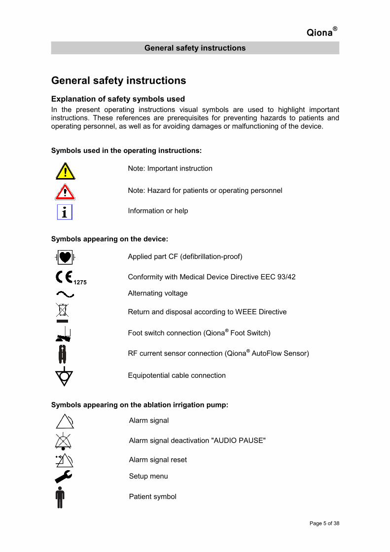
Explanation of safety symbols used
In the present operating instructions visual symbols are used to highlight important instructions. These references are prerequisites for preventing hazards to patients and operating personnel, as well as for avoiding damages or malfunctioning of the device.
Symbols used in the operating instructions:
Note: Important instruction
Note: Hazard for patients or operating personnel
Information or help
Symbols appearing on the device:
Applied part CF (defibrillation-proof)
1275 Conformity with Medical Device Directive EEC 93/42
Alternating voltage
Return and disposal according to WEEE Directive
Foot switch connection (Qiona® Foot Switch)
RF current sensor connection (Qiona® AutoFlow Sensor)
Equipotential cable connection
Symbols appearing on the ablation irrigation pump:
Alarm signal
Alarm signal deactivation "AUDIO PAUSE"
Alarm signal reset
Setup menu
Patient symbol

Qiona®
General safety instructions
Page 6 of 38
LOW flow rate
HIGH flow rate
Maximum flow rate in rinse function
Infusion bottle/container level indicator
Infusion bottle/container change confirmation button
Normal overpressure detection active
Sensitive overpressure detection active
Scroll through Setup Menu
Exit Setup Menu
Symbols appearing on the packaging:
Observe operating instructions
Order Number
Lot Number
Serial Number
Unit quantity in packaging
Expiration date
Sterilised with ethylene oxide
Single use
Do not resterilise
Do not use if packaging is damaged
Store in a dry place
Manufacturer
Distributor
Overall length

Qiona®
General safety instructions
Page 7 of 38
A thorough knowledge and observance of the present operating instructions provided as an integral part of the product are a prerequisite for using the Qiona® ablation irrigation pump. Store the ablation irrigation pump operating instructions carefully. The present operating instructions do not replace instructions given to the operator/user by the manufacturer's authorized medical device consultant. The device must be used only by persons who have the required training or knowledge and experience.
The performance, safety and electromagnetic compatibility of the device may be affected by the use of non-original parts.
Manufacturer's liability
The manufacturer is responsible for the safety, reliability and serviceability of the device in the following cases: Assembly, upgrades, adjustments, changes or repairs performed only by persons authorized by the manufacturer. The electrical installation of the medicinally used room must comply with the appropriate regulations (i. e. VDE 0100, VDE 0107 or IEC regulation) and the device must be used according to the operating manual. In addition, country-specific regulations and national deviations must be complied with. The manufacturer undertakes to accept returned old devices according to the Electronic Equipment Act.
Operator's obligations
The owner of the device must accept responsibility for the proper operation of the medical device. In terms of the regulations relating to operators of medical devices, the user is subject to comprehensive obligations, as well as responsibilities concerning his/her activities when handling medical devices. Only qualified personnel is permitted to use the Qiona
® ablation irrigation pump. The present operating manual does not replace the instructions provided to the user by the device owner. A clinical application may only take place following instruction by qualified personnel.
Use the device only on a mains power supply fitted with a protective grounding conductor. The mains voltage must conform with the indications provided on the identification plate on the back of the device. Liquids must not penetrate parts of the device which carry electrical voltage. Do not spray cleaning agents in the connector socket or air bubble sensor. Disconnect the device plug before cleaning. All connecting cables must be replaced in the event when minor damages are detected and must not be rolled over. Plugs must not be forcefully pushed into sockets. When removing plugs, do not pull on the cable but rather loosen the push-pull locking or screwing mechanism where needed.
Furthermore, observe the safety instructions in the operating manuals of devices (ablation catheters, generators) which are operated together with the Qiona®.
Qiona®
General safety instructions
Page 8 of 38
Additional accessories
Additional accessories that are beyond the scope of delivery of the present device and are connected to the analog and digital interfaces of the device must be proven to comply with the relevant EN specifications (e.g. EN 60601 for electrical medical devices). In addition, all configurations must be in accordance with the current valid version of the EN 60601-1 standard. Operators installing additional devices are required to configure these and are, therefore, responsible for ensuring that these devices comply with the current version of the aforementioned EN 60601-1 standard.
Equipotential cable
It is important to limit potential variances between the different parts of a system within the patient's environment. In limiting this potential variance by using a system of protective grounding conductors, the quality of the connection is of utmost importance. It is, therefore, essential to avoid a failure in the protective measures in each part of the system. In the event of a fault in a protective grounding conductor connection in one of the devices within the patient's environment, this potential variance can present itself in the casing of the device and constitute a danger to the user and patient if the user touches the device and the patient simultaneously.
Single-use
Reuse of single-use devices creates a potential risk of patient or user infections. Contamination of the device may lead to injury, illness or death of the patient. Cleaning, disinfection and sterilisation may compromise essential material and design characteristics leading to device failure.
Statement regarding DEHP and BPA
The Qiona® Tube product family does not contain Bis(2-ethyhexyl) phthalate (DEHP) and Bisphenol A (BPA)."
Qiona®
Purpose
Page 9 of 38
Purpose
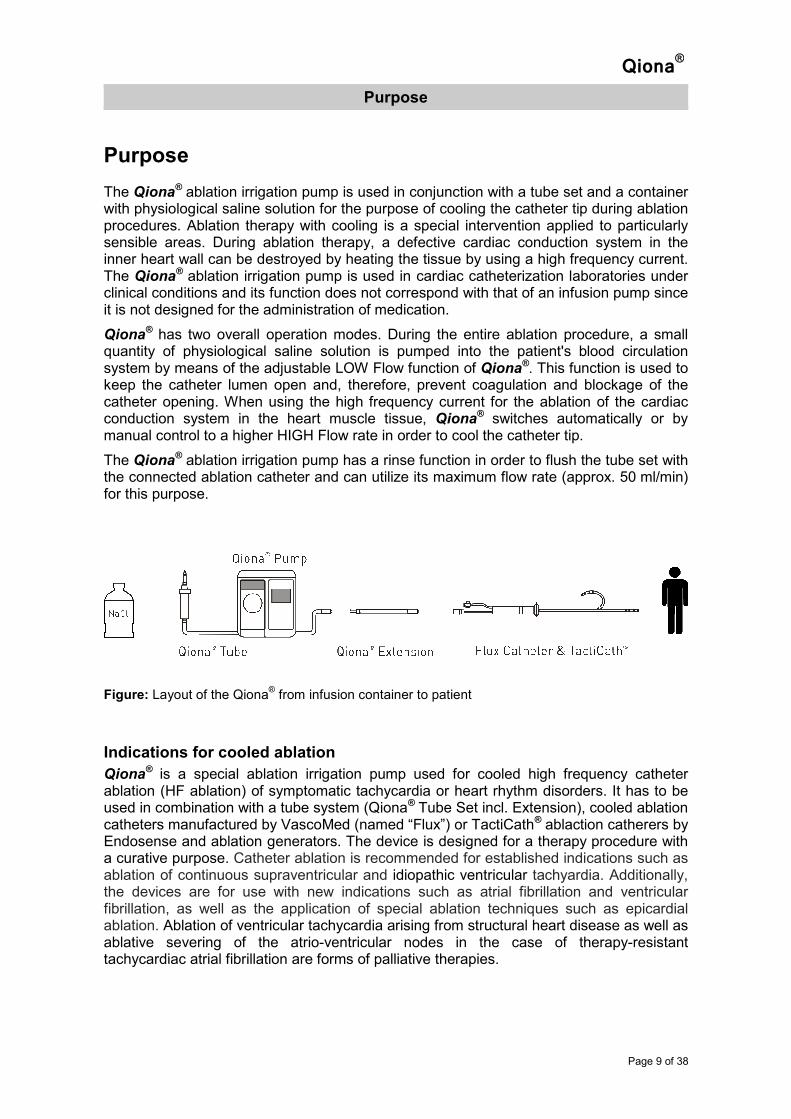
The Qiona® ablation irrigation pump is used in conjunction with a tube set and a container with physiological saline solution for the purpose of cooling the catheter tip during ablation procedures. Ablation therapy with cooling is a special intervention applied to particularly sensible areas. During ablation therapy, a defective cardiac conduction system in the inner heart wall can be destroyed by heating the tissue by using a high frequency current. The Qiona® ablation irrigation pump is used in cardiac catheterization laboratories under clinical conditions and its function does not correspond with that of an infusion pump since it is not designed for the administration of medication.
Qiona® has two overall operation modes. During the entire ablation procedure, a small
quantity of physiological saline solution is pumped into the patient's blood circulation system by means of the adjustable LOW Flow function of Qiona®. This function is used to keep the catheter lumen open and, therefore, prevent coagulation and blockage of the catheter opening. When using the high frequency current for the ablation of the cardiac conduction system in the heart muscle tissue, Qiona® switches automatically or by manual control to a higher HIGH Flow rate in order to cool the catheter tip.
The Qiona® ablation irrigation pump has a rinse function in order to flush the tube set with the connected ablation catheter and can utilize its maximum flow rate (approx. 50 ml/min) for this purpose.
Figure: Layout of the Qiona
® from infusion container to patient
Indications for cooled ablation
Qiona® is a special ablation irrigation pump used for cooled high frequency catheter
ablation (HF ablation) of symptomatic tachycardia or heart rhythm disorders. It has to be used in combination with a tube system (Qiona® Tube Set incl. Extension), cooled ablation catheters manufactured by VascoMed (named “Flux”) or TactiCath® ablaction catherers by Endosense and ablation generators. The device is designed for a therapy procedure with a curative purpose. Catheter ablation is recommended for established indications such as ablation of continuous supraventricular and idiopathic ventricular tachyardia. Additionally, the devices are for use with new indications such as atrial fibrillation and ventricular fibrillation, as well as the application of special ablation techniques such as epicardial ablation. Ablation of ventricular tachycardia arising from structural heart disease as well as ablative severing of the atrio-ventricular nodes in the case of therapy-resistant tachycardiac atrial fibrillation are forms of palliative therapies.
Qiona®
Purpose
Page 10 of 38
Contraindications
Absolute contraindications
• Active systemic infection
• Sepsis
• Hypercoagulation
• Verified atrial/ventricular thrombus
• Decompensated heart insufficiency
Relative contraindications
• Anomalies in vein selected for catheter insertion
• Leg vein or pelvic axis thrombosis
• Patients with artificial cardiac valves
Complications
• Death
• Stroke
• Cardiac valve damage
• Cardiac infarct
• Embolism, such as lung embolism
• Severe rhythm disorders
• Life-threatening ventricular arrhythmia
• Bradycardia
• Sinus arrest
• AV blockage
• Need for pacemaker implantation
• Supraventricular tachycardia
• Asystole
• Decompensation of a previously existing cardiac/kidney insufficiency
• Hypotension
• Vasovagal reaction
• Vein thrombosis
• Coronary sinus perforation
• Damage to the endocardium and perforation of the heart
• Pulmonary vein stenosis
• Stenosis of the superior vena cava
• Atrio-esophageal fistula
• Pericardial effusion
• Pericardial tamponade
• Hemothorax in the event of puncture of the vena subclavia
Qiona®
Purpose
Page 11 of 38
• Pneumothorax in the event of puncture of the vena subclavia
• Damage and perforation of nerves, arteries and/or veins
• Pseudoaneurysm in groin area due to application of catheter technique
• Arterio-venous fistula
• Endocarditis
• Pericarditis
• Fever
• Burns
• General systemic infections
Combination with other products
The Qiona® ablation irrigation pump may only be used together with the Qiona® Tube Set incl. Extension (REF: 365775)
The Qiona® Tube Set incl. Extension may only be connected to cooled ablation catheters named “Flux” from the company VascoMed with their various curve configurations and, where applicable, with the gold tip, or with TactiCath® ablation catheters by Endosense. The body of these ablation catheters has a lumen through which the cooling fluid can be pumped to the catheter tip, via a temperature monitoring element which must always be used in applications with Qiona®.
Furthermore, optional accessories that can be connected to the Qiona® include:
• The Qiona® Foot Switch (REF: 365773) and
• The Qiona® AutoFlow Sensor (REF: 365774).
Patient population & residual risk
There are no restrictions with regard to the patient population. The device can be used on any age group, patients with any health condition and all ethnic groups. The patient does not operate the device.
Residual risk for patients lies primarily in the selection of ablation parameters which may be unsuitable for the patient or other incorrect applications.

Qiona®
Product description
Page 12 of 38
Product description
Figure: Front view of the Qiona® ablation irrigation pump
The Qiona® is turned on and off by means of the ON/OFF switch located at the back. All functions are performed via the embossed soft keys on the key pad.
Key pad and display layout
Figure: View of the key pad for the Qiona
® ablation irrigation pump
Connection options on the rear side
Figure: View of the back of the Qiona® with connections
Plug connector for equipotential cable
Plug connector for
RF current sensor or foot switch
Service update connections ON/OFF switch with mains cable socket
START/STOP button
Pump flow operating light (green)
Volume indicator for saline
solution added
HIGH Flow delivery rate
Soft key button "HIGH Flow"
Saline solution level
UP/DOWN buttons
Soft key button "LOW Flow"
LOW Flow delivery rate
RINSE button
3 alarm display LEDs (yellow)
Soft key button for "SETUP"
Overpressure
detection
Pump rotor Pressure sensor Air bubble sensor Irreversible
tube set attachment
3 alarm display LEDs (yellow) Display Pole mount Key pad
Supporting feet

Qiona®
Installation and startup
Page 13 of 38
Installation and startup
Ensure that the packaging is delivered undamaged. Inspect the Qiona®
ablation irrigation pump for any damage prior to use. In the event that the product has defects, it should not be used and the supplier must be informed accordingly.
Transport and storage instructions
Temperature -10° C to +50° C
Humidity less than 90% rel. humidity
Weight with packaging: approx. 6 kg
Dimensions of the Qiona® with packaging: Width x Height x Depth: 450 mm x 400 mm x 475 mm
Unpacking the device and inspecting delivery
The Qiona® is delivered in a cardboard package. When unpacking the Qiona®, make sure that all of the parts are removed from the package.
The Qiona® is delivered with the following parts:
• Qiona® ablation irrigation pump,
• Three-pole mains cable Type F,
• Operating instructions in German,
• Operating instructions in English,
• Qiona® Tube Set incl. Extension, and
• Qiona® Pole Adapter Set It is advisable not to dispose of the packaging and to use it again for any service required.
Startup
First, remove the Qiona® from its packaging and place it in a suitable stable place.
The Qiona® can be installed:
• in a suitable place, or
• on the current infusion stand. Ensure that it is firmly fitted onto the infusion stand.
Connect the mains cable to the back of the Qiona® casing and insert into a socket with a protective grounding conductor. Observe the voltage indicated on the identification plate. The Qiona® can be operated by turning on the ON/OFF switch. The Qiona® must be positioned so as to ensure that the ON/OFF switch can easily be operated to turn it off. Refer to chapter "Application and Operation" in order to startup and operate the Qiona®.

Qiona®
Application and Operation
Page 14 of 38
Application and operation
Overview of primary operating functions
Figure: Overview of application and operation of the Qiona®
1 Unpacking and connecting
the Qiona®
2 Turn on the Qiona® 3 Pre-setting
and Setup
4 Open front panel 5 Unpack the Qiona® Tube
Set incl. Extension
6 Insert the Qiona®
Tube
7 Close front panel 8 Connect infusion container or
infusion bottle
10 Connect ablation catheter 11 Perform rinsing 12 Start application
9 Remove the Qiona®
Extension

Qiona®
Application and Operation
Page 15 of 38
1 Unpacking and connecting the Qiona®
Remove the Qiona® from its packaging and connect it either to the infusion stand or position it on a suitable level surface. In the event that the pole diameter is too small, use the Qiona® Pole Adapter Set to compensate. Connect the mains cable firstly to the Qiona
® and then into a socket. If you wish to use a RF current
sensor (Qiona® AutoFlow Sensor) or foot switch (Qiona® Foot Switch) as accessories to the Qiona®, you can connect an accessory to the back of the device casing into the appropriately marked plug connector.
2 Turn on the Qiona®
Place the ON/OFF switch at the back of the device in the ON position (I) in order to begin operating the Qiona®. The Qiona® will perform a self-test. After the self-test, the display always shows the pump status to be in "Stop" mode. The settings for the HIGH Flow and LOW Flow of the last application are shown on the display. The settings of the previous application are automatically carried over into the new application. While in "Stop" mode, the pump can immediately be started, settings entered into the Setup menu or flow rates preset.
The following three options are available:
• Keep all settings and go to Point 4.
• Change application settings and go to Point 3.1.
• Change settings in the Setup menu and go to Point 3.2.
3 Pre-setting and Setup
3.1 Pre-setting
Use the soft key buttons in "Stop" mode to switch between LOW Flow and HIGH-Flow and the UP and DOWN buttons to adjust the values (see Stop mode illustration on next page). The adjusted value is highlighted.

Qiona®
Application and Operation
Page 16 of 38
The setting values are adjusted with the UP and DOWN buttons. The changed values are automatically accepted without the need for confirmation. If the UP/DOWN buttons are not pressed within two seconds, the highlighted value will become inactive again.
3.2 Setup Menu
The "Pump Setup" menu is accessed by pressing the "Setup (wrench)“ soft key button. This function is only available before or after an application. The button is locked during an application. The user can set all required operating parameters of the Qiona® in the "Pump Setup“ (STOP) operating mode. The individual menu items can be selected by using the "Scroll" soft key button.
Each value changed is automatically accepted without requiring confirmation. The values of the previous application, with the exception of the dispensed cooling fluid quantity, are saved.
Figure: Overview of setting options in the Qiona® Setup Menu
3.2.1 Clear
By using the UP or DOWN buttons, this function resets the current volume indicator to zero (similarly when switching the Qiona® on or off).
3.2.2 Overpressure detection
This function sets the overpressure sensitivity of the Qiona®. Two options are available:
• The sensitive overpressure detection function indicated with the symbol should be selected for ablation catheters which work with a relatively low operating pressure due to a relatively large flush tube diameter. This setting is recommended for "Flux" cooled ablation catheters by VascoMed. The HIGH flow mode can be set to a maximum of 50 ml/min.
Soft key button
"EXIT"
Soft key button
"SCROLL"
UP / DOWN buttons
Soft key button "HIGH Flow"
Soft key button "SETUP Menu"
Soft key button "LOW Flow"
Figure: Stop mode

Qiona®
Application and Operation
Page 17 of 38
• The normal overpressure detection system (default value) indicated with the symbol should be selected, in contrast, for ablation catheters with small flush tube diameters and, therefore, higher operating pressures. This setting is recommended for "TactiCath®" cooled ablation catheters by Endosense. The HIGH flow mode can be set to a maximum of 35 ml/min.
3.2.3 Size
This function establishes the volume of the infusion bottle or container.
- Range of values: off – 5000 ml - Increment in change of volume: 250 ml - Default value: off
In the case that the volume is adjusted to 0 ml, the text "Off" appears instead of the figure together with a unit of measure. The indication of infusion volume is deactivated during the application.
3.2.4 Alarm at
This function activates an alarm signal when the set residual volume of the container is reached. The residual volume indication is expressed in percentage.
- Range of values: off – 50 % - Increment in change of residual volume indicator: 5 % - Default value: off In the case that the volume is adjusted to 0 ml ("off" displayed), this parameter is deactivated and is no longer visible to the user. As soon as the setting is > 0 ml, the parameter will once again be visible.
3.2.5 HIGH Flow – Time delay
A time delay can be set with this function. When the Qiona® flow is switched from HIGH Flow to LOW Flow, the system will remain in HIGH Flow mode for the period of the time delay set.
- Range of values: 0 s – 15 s - Increment : 1 s - Default value: 3 s
In the case of a time delay of 0 s, the text "Off" will appear instead of the figure together with the unit of measure and the time delay will be deactivated.
3.2.6 Display brightness
This function is used to adjust the display brightness.
- Range of values: 10 % – 100 % - Increment : 5 % - Default value: 50 % The display brightness is limited to a minimum value so as to guarantee the operability of the Qiona® at any setting.

Qiona®
Application and Operation
Page 18 of 38
3.2.7 Display contrast
This function is used to adjust the display contrast.
- Range of values: 10 % – 100 % - Increment : 5 % - Default value: 50 %
3.2.8 Service
Service menu setup. This function is reserved for use by the manufacturer.
3.2.9 Exit Setup menu
When the "EXIT" soft key button is pressed, the device changes to "Stop" mode.
4 Open front panel
5 Unpack the Qiona® Tube Set incl. Extension
A Qiona® Tube Set incl. Extension is included in the packaging of each new Qiona®. Unpack this set and open only the outer packaging.
6 Insert the Qiona® Tube
Adapter 1 Adapter 2
Remove the Qiona® Tube from its packaging and insert the tube into the Qiona®. The Qiona® Tube has two pump adapters (Adapter 1 and Adapter 2). Insert Adapter 1 (the adapter which is closest to the drop chamber) into the Qiona®. Each adapter entry point of the Qiona® is designed so that an incorrect fitting is not possible. Once you have fitted Adapter 1, hold Adapter 2 in your hand and insert the tube over the rotor into the Qiona®. Press the tube behind the motor downwards with your left index finger (see illustration above). At the same time, using your right hand in which you hold Adapter 2, pull the tube
To open the front panel, reach under and pull up the panel until it engages. When the front panel is open, the pump is stopped.
Qiona® Tube Set incl.
Extension: Qiona
® Tube
Qiona® Extension
Adapter 1 Adapter 2

Qiona®
Application and Operation
Page 19 of 38
through the right slit in the Adapter 2 entry point. Ensure that the tube is inserted as firmly as possible into the slit.
If the tube does not fit firmly enough in the air bubble sensor intake point, faulty readings will be taken by the air bubble sensor. In this case, insert the filled tube set once again. Ensure that you pull it sufficiently firmly into the air bubble sensor intake so that the sensor LED lights up green.
7 Close front panel
8 Connect infusion container or infusion bottle
9 Remove the Qiona® Extension
10 Connect ablation catheter
After inserting the tube into the ablation irrigation pump, close the front panel.
Hold the drop chamber by hand and remove the protective cap. Connect the drop chamber to the infusion pouch or infusion bottle containing the relevant fluid. Ensure that the drop chamber is always free and hangs down perpendicularly in order to avoid air bubbles.
Remove the Qiona® Extension from the sterile packaging.
Remove the protective cap of the Luer connector and execute a sterile tube connection between the Qiona® Tube and the Qiona® Extension, as well as the ablation catheter.
The Qiona® may only be connected to cooled ablation catheters with their various curve configurations and to gold tip catheter versions where applicable, such as the Flux catheters by VascoMed or TactiCath® by Endosense. Ensure that the Luer connections are always closed and the temperature monitor of the HF generator is activated.

Qiona®
Application and Operation
Page 20 of 38
11 Perform rinsing
Figure A: Key pad Figure B: Stop mode
12 Start application
Rinsing or flushing of the entire tube system with the connected ablation catheter is of utmost importance. The RINSE button must be held permanently pressed. The indicator display changes to Rinse mode (Fig. A on next page). As long as the RINSE button is pressed, the pump will function on maximum capacity of 50 ml/min in order to flush the tube set and ablation catheter.
It is the user's responsibility to continue the rinse process until it is certain that no air remains in the tube system and catheter.
The air bubble sensor is deactivated during rinsing in order to avoid any alarm signal. The green LED of the air bubble sensor indicates that there are no air bubbles within the range of the sensor and that the tube set is firmly fitted into the air bubble sensor inlet point. In the event that the air bubble sensor LED does not turn green after the tube set has been bled despite the fact that the tube set does not indicate any air bubbles, pull the filled tube set once again firmly into the air bubble sensor inlet point until the sensor LED lights up green.
START/STOP button RINSE button
The application is started by using the START/STOP button.
The pressure monitoring sensor is active during rinsing. In the event of overpressure, an optical and acoustic alarm is activated and the pump stops immediately.
If the RINSE button is released the rinse process is ended and the pump changes once again to Stop mode (Fig. B).

Qiona®
Application and Operation
Page 21 of 38
With a manual start, the Qiona® sets the pump to LOW Flow mode. The LOW Flow value is highlighted and the Qiona® pumps the volume set. The green running light at the top of the display indicates that the Qiona® is functioning.
If a HF signal is detected by the flow sensor already at startup, the Qiona
® changes immediately to HIGH Flow mode.
If the "Size" and "Alarm at" functions in the SETUP menu are activated, a blue bottle appears in the top left corner of the display. The blue bottle indicated the current level in the infusion container or bottle provided that the total volume has been entered correctly in the "Size" Setup menu. The digital value next to the patient symbol indicates the current volume of dispensed saline solution.
The switch from LOW Flow to HIGH Flow, as well as back to LOW Flow is executed by means of:
• the soft key button on the Qiona®, or
• the optional foot switch (Qiona® Foot Switch), or
• the optional RF current sensor (Qiona® AutoFlow Sensor).

Qiona®
Application and Operation
Page 22 of 38
Switch-over options
Switch-over by means of soft key button: By using the HIGH Flow soft key button, the flow can be switched from LOW Flow to HIGH Flow. The Qiona® switches immediately to HIGH Flow mode. The value set is highlighted. Press the LOW Flow soft key button to switch the flow back to LOW.
Switch-over by means of foot switch (Qiona® Foot Switch): By using the optional foot switch which can be connected to the back of the Qiona®, the flow can be switched from LOW to HIGH and back. Press the foot switch button in order for the ablation irrigation pump to immediately switch to the HIGH Flow value entered. The value set is highlighted on the display. When the foot switch is released, the Qiona® switches back to LOW Flow.
Switch-over by means of RF current sensor (Qiona ® AutoFlow Sensor):
The optional RF current sensor which can be connected to the back of the Qiona® can be used to switch the flow automatically between LOW Flow and HIGH Flow, according to the flow required for the ablation. Clamp the RF current sensor to the connecting cable between the HF generator and ablation catheter. The green LED of the RF current sensor indicates that the system is ready to operate. The Qiona® switches immediately to the HIGH flow set for as long as the RF current sensor detects a continuous HF signal. A yellow LED indicates that the RF current sensor has detected a HF signal. As soon as the HF signal stops, the flow will either be immediately switched back to LOW or will do so after a time delay if applicable.
Ensure that the RF current sensor is not laid on the floor and is firmly attached to the connecting cable.
Figure: Configuration using the RF current sensor (Qiona® AutoFlow Sensor)
The activation threshold of the RF current sensor is shown in the following diagram which indicates the combinations of impedance Z and performance output P required to ensure a definite activation. Only the combinations above the curve will result in the switch from LOW flow to HIGH flow. A further prerequisite is that the ablation generator operates with a
frequency of approx. 500 kHz (± 10%).
Figure: Activation threshold of the RF current sensor (Qiona® AutoFlow Sensor)
0,1
1
10
100
0 50 100 150 200 250 300 350 400 450 500
Impedance Z [ΩΩΩΩ]
Perform
ance P [W]
Activation threshold of the RF current sensor
Qiona®
Application and Operation
Page 23 of 38
Time delay function
A time delay of max. 15 seconds in switching from HIGH flow to LOW flow can be set in the Qiona® Setup menu.
The time delay is activated when the Qiona® is switched from HIGH to LOW flow by the RF current sensor signal, foot switch or a manual operation of the key pad. During the time delay, the Qiona® continues to operate in HIGH flow mode for the period preset in the SETUP menu (max. 15 seconds) and switches automatically to LOW flow after the time delay. However, during the time delay the Qiona® accepts user commands and executes these. Soft key button commands using the Qiona® key pad always have priority over RF current sensor or foot switch signals. In the event that the Qiona® receives a HIGH flow signal from the foot switch or RF current sensor during the time delay, it will immediately switch back to HIGH flow mode. The time delay can be overridden when the soft key button LOW-Flow on the Qiona® key pad is pressed during this period.
The time delay should be at least 1 to 5 seconds in order to avoid that the Qiona® switches over for brief periods due to generator transients.
Volume indicator function
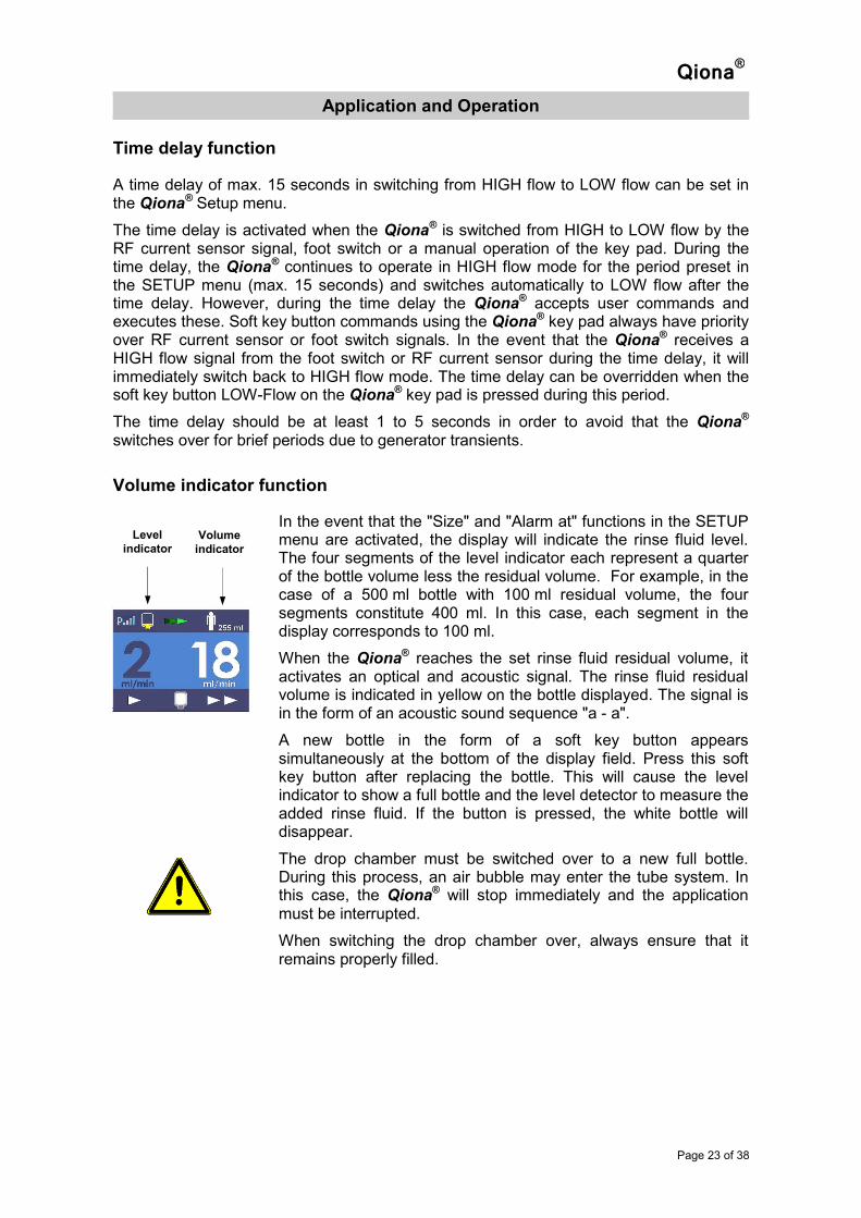
In the event that the "Size" and "Alarm at" functions in the SETUP menu are activated, the display will indicate the rinse fluid level. The four segments of the level indicator each represent a quarter of the bottle volume less the residual volume. For example, in the case of a 500 ml bottle with 100 ml residual volume, the four segments constitute 400 ml. In this case, each segment in the display corresponds to 100 ml.
When the Qiona® reaches the set rinse fluid residual volume, it activates an optical and acoustic signal. The rinse fluid residual volume is indicated in yellow on the bottle displayed. The signal is in the form of an acoustic sound sequence "a - a".
A new bottle in the form of a soft key button appears simultaneously at the bottom of the display field. Press this soft key button after replacing the bottle. This will cause the level indicator to show a full bottle and the level detector to measure the added rinse fluid. If the button is pressed, the white bottle will disappear.
The drop chamber must be switched over to a new full bottle. During this process, an air bubble may enter the tube system. In this case, the Qiona® will stop immediately and the application must be interrupted.
When switching the drop chamber over, always ensure that it remains properly filled.
Level
indicator Volume
indicator
Qiona®
Application and Operation
Page 24 of 38
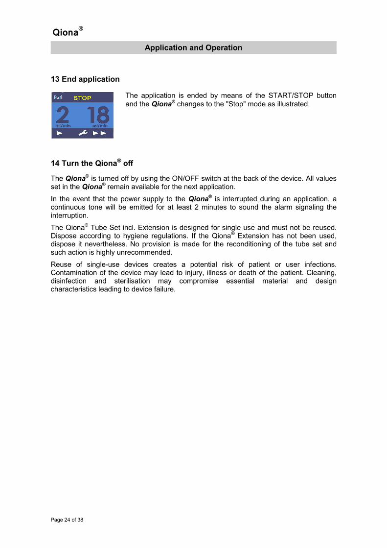
13 End application
14 Turn the Qiona® off
The Qiona® is turned off by using the ON/OFF switch at the back of the device. All values set in the Qiona® remain available for the next application.
In the event that the power supply to the Qiona® is interrupted during an application, a continuous tone will be emitted for at least 2 minutes to sound the alarm signaling the interruption.
The Qiona® Tube Set incl. Extension is designed for single use and must not be reused. Dispose according to hygiene regulations. If the Qiona® Extension has not been used, dispose it nevertheless. No provision is made for the reconditioning of the tube set and such action is highly unrecommended.
Reuse of single-use devices creates a potential risk of patient or user infections. Contamination of the device may lead to injury, illness or death of the patient. Cleaning, disinfection and sterilisation may compromise essential material and design characteristics leading to device failure.
The application is ended by means of the START/STOP button
and the Qiona® changes to the "Stop" mode as illustrated.

Qiona®
Alarm signals and corrective measures
Page 25 of 38
Alarm signals and corrective measures
Presence of an alarm condition
Figure: Alarm condition display
In the event of an alarm condition, the display indicates the relevant reference (see Alarm System Overview) marked by yellow LEDs. Simultaneously, an acoustic alarm signal with the tone sequence "e - c“ is emitted.
The acoustic signal can be turned off for 2 minutes using the soft key button "Audio pause“. By using the soft key button "Alarm Reset", the user confirms that the cause for the alarm has been remedied. The Qiona® returns to normal settings and the application can be continued.
The Qiona® stops immediately in the presence of any alarm condition signal.
Testing alarm functions
If the Qiona® is turned on at the mains switch, a brief Beep sound is emitted and the yellow LED lights up briefly. A function test is also performed. Another acoustic information signal is emitted and the software version of the Main (FwM) and Watchdog (FwW) controllers are shown temporarily on the display.
With a view to assess risk, the Qiona® alarm system ensures that in the event of an alarm during proper use of the device, the user can always be informed accordingly by means of optical or acoustic alarm signals (i.e. the user must always be within hearing and/or visual range). The Qiona® is designed with a technical alarm condition system. The alarm condition priority is set at "Low Priority" for all alarm conditions. The Qiona® transmits visual and acoustic alarm signals.
Alarm signal Audio pause Alarm
reset
Qiona®
Alarm signals and corrective measures
Page 26 of 38
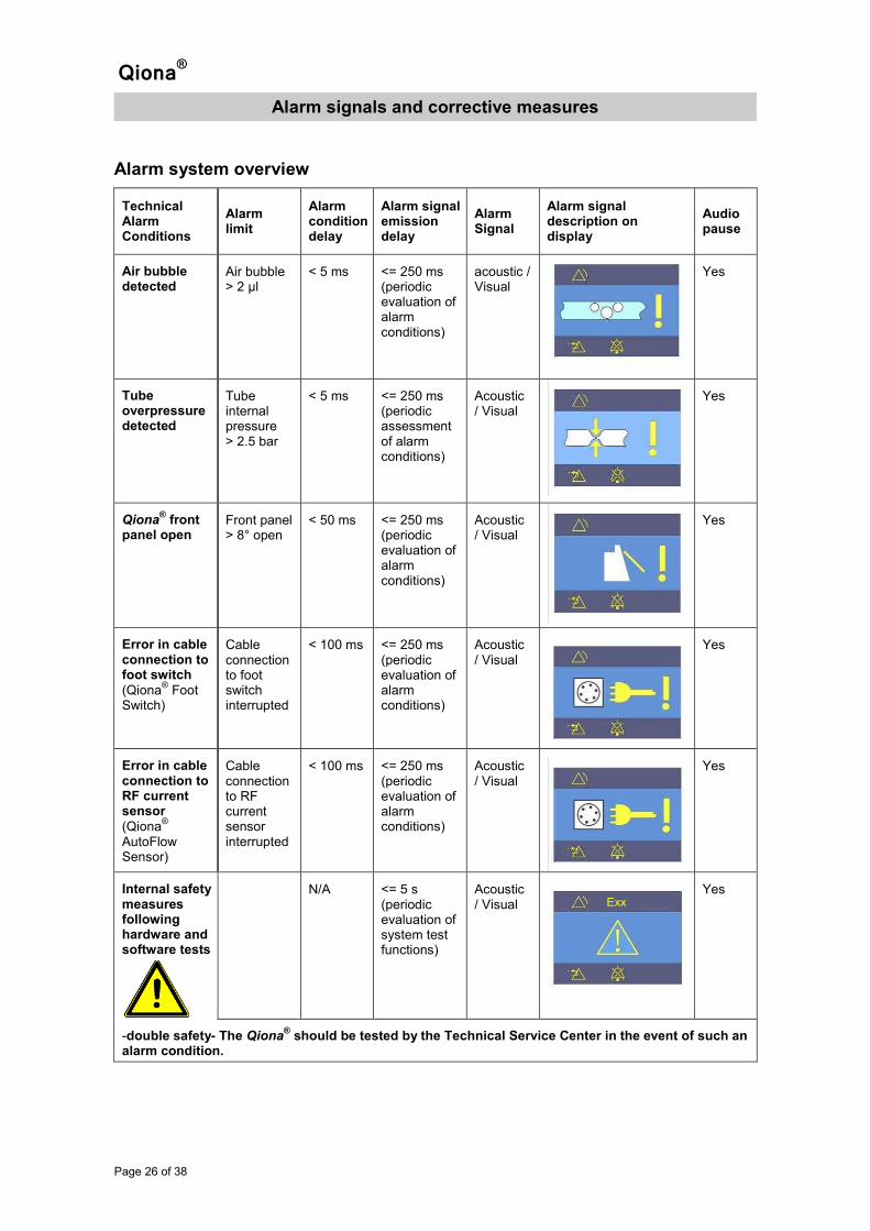
Alarm system overview
Technical Alarm Conditions
Alarm limit
Alarm condition delay
Alarm signal emission delay
Alarm Signal
Alarm signal description on display
Audio pause
Air bubble detected
Air bubble > 2 µl
< 5 ms <= 250 ms (periodic evaluation of alarm conditions)
acoustic / Visual
Yes
Tube overpressure detected
Tube internal pressure > 2.5 bar
< 5 ms <= 250 ms (periodic assessment of alarm conditions)
Acoustic / Visual
Yes
Qiona® front
panel open Front panel > 8° open
< 50 ms <= 250 ms (periodic evaluation of alarm conditions)
Acoustic / Visual
Yes
Error in cable connection to foot switch (Qiona
® Foot
Switch)
Cable connection to foot switch interrupted
< 100 ms <= 250 ms (periodic evaluation of alarm conditions)
Acoustic / Visual
Yes
Error in cable connection to RF current sensor (Qiona
®
AutoFlow Sensor)
Cable connection to RF current sensor interrupted
< 100 ms <= 250 ms (periodic evaluation of alarm conditions)
Acoustic / Visual
Yes
Internal safety measures following hardware and software tests
N/A <= 5 s (periodic evaluation of system test functions)
Acoustic / Visual
Yes
-double safety- The Qiona® should be tested by the Technical Service Center in the event of such an
alarm condition.
Exx
Qiona®
Alarm signals and corrective measures
Page 27 of 38
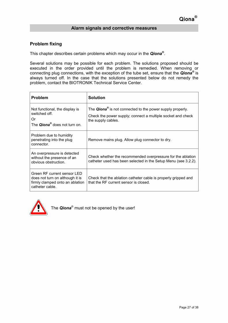
Problem fixing
This chapter describes certain problems which may occur in the Qiona®. Several solutions may be possible for each problem. The solutions proposed should be executed in the order provided until the problem is remedied. When removing or connecting plug connections, with the exception of the tube set, ensure that the Qiona® is always turned off. In the case that the solutions presented below do not remedy the problem, contact the BIOTRONIK Technical Service Center.
Problem Solution
Not functional, the display is switched off.
Or
The Qiona® does not turn on.
The Qiona® is not connected to the power supply properly.
Check the power supply; connect a multiple socket and check the supply cables.
Problem due to humidity penetrating into the plug connector.
Remove mains plug. Allow plug connector to dry.
An overpressure is detected without the presence of an obvious obstruction.
Check whether the recommended overpressure for the ablation catheter used has been selected in the Setup Menu (see 3.2.2).
Green RF current sensor LED does not turn on although it is firmly clamped onto an ablation catheter cable.
Check that the ablation catheter cable is properly gripped and that the RF current sensor is closed.
The Qiona® must not be opened by the user!

Qiona®
Alarm signals and corrective measures
Page 28 of 38
Service
In the event that no solution can be found for the problem, contact the appropriate BIOTRONIK Technical Service Center.
Each time the Qiona® is returned, a suitable disinfection procedure must be performed to avoid the risk of infection. Consumables must be disposed in accordance with hygiene regulations.
Never open the device when it is connected to the mains power supply. Beware that even when disconnected from the mains, internal parts of the device may still be energized.
Alarm system description
Terms Definitions Applicability to the Qiona® Explanation
Alarm condition
Condition of the alarm system once it has determined a possible or real threat.
• Air bubble
• Overpressure in tube system
• Front panel not closed
• Motor jam
• Foot switch connection broken down
• RF current sensor connection broken down
• Technical error
Alarm condition delay
Time between occurrence of an alarm condition either on the patient side (PHYSIOLOGICAL ALARM CONDITION), or on the device side (TECHNICAL ALARM CONDITION), up to system determination of an existing threat.
No possible setting
Alarm limit Limit value used by an alarm system to determine an alarm condition.
• Air bubble > 2 Microliters
• Internal tube pressure > 2.5 bar
• Front panel > 8° open
• No connection to foot switch
• No connection to Qiona®
AutoFlow Sensor
Alarm OFF Condition of indefinite duration in which an alarm system or a part of an alarm system does not generate alarm signals.
No setting possible

Qiona®
Alarm signals and corrective measures
Page 29 of 38
Terms Definitions Applicability to the Qiona® Explanation
Alarm presetting
Set of saved configuration parameters, including selection of algorithms and initial values for using algorithms, which affect or change the functioning of the alarm system.
No setting possible
Alarm settings Alarm system configuration including but not restricted to:
• Alarm limits,
• Properties of all conditions of alarm activation, and
• Values of parameter variables, which determine the function of the alarm system.
No setting possible
Alarm signal Signal type created by the alarm system to display the existence (or the occurrence) of an alarm condition.
• Optical alarm signal by yellow LED on the key pad
• Optical alarm signal via display
• Acoustic alarm signal with a noise pressure level of 55 dB(A) at a distance of 1 meter.
Delay in alarm emittance
Time from start of alarm condition to emittance of alarm signal.
No setting possible
Audio OFF Condition of indefinite duration during which the alarm system or a part of the alarm system does not generate an acoustic alarm signal.
No setting possible Refers to all alarm conditions active at the moment the button is pressed.
Audio pause Condition of specific duration during which the alarm system or a part of the alarm system does not generate an acoustic alarm signal.
2 minutes Refers to all alarm conditions active at the moment the button is pressed.
De-escalation Process which the alarm system uses to lower the priority of an alarm condition or the urgency of an alarm signal.
No application
Escalation Process which the alarm system uses to raise the priority of an alarm condition or the urgency of an alarm signal.
No application
Incorrect negative alarm condition
Missing alarm condition, if a valid triggering occurrence in the patient, in the device or in the alarm system has
Double safety measure

Qiona®
Alarm signals and corrective measures
Page 30 of 38
Terms Definitions Applicability to the Qiona® Explanation
occurred.
Incorrect positive alarm condition
Existing alarm condition, if no valid triggering occurrence in the patient, in the device or in the alarm system has occurred.
Results in safe condition of the device.
Information signal
Every signal, which is not an alarm or reminder signal.
Applies.
Recurring alarm signal
Alarm signal which continues to emit after its triggering occurrence has been eliminated, until it is stopped with a deliberate operator action.
Applies.
Non-recurring alarm signal
Alarm signal which automatically stops being emitted once the triggering occurrence no longer exists.
Does not apply.
Physiological alarm condition
Alarm condition originating from a monitored patient-related variable.
Does not apply.
Technical alarm condition
Alarm condition originating from a monitored device or alarm system-related variable.
Applies.
Alarm reset Action performed by operator to cancel an alarm signal for which there is no currently associated alarm condition.
Applies.
Qiona®
Maintenance
Page 31 of 38
Maintenance
Cleaning and disinfection
• No humidity must be allowed to enter into the device.
• Before cleaning and disinfecting the device surfaces, disconnect the mains plug.
• Use lint-free, soft cloths. Clean with a damp cloth, using a mild soap solution or 70% isopropyl alcohol.
• Use a solution of 70% isopropanol and 30% water to disinfect the device. Lysoformin 3000: 2% concentration, allow 15 minutes to take effect. The cleaning and disinfecting solutions must have evaporated before using the device.
• Visual check: The sockets of all connections and cable plugs must be free of all dirt.
Service
Repairs, upgrades or changes to the ablation irrigation pump system may only be performed by BIOTRONIK or a company specifically authorized by the manufacturer. In the latter case, the work performed must be documented, signed and dated. Changes to the device by third parties are not permitted. A technical safety check must be performed at least every 12 months. Use the Qiona® only if the device is functionally and/or operationally safe. If this is not the case, have it immediately serviced.
Disposal
The present device contains material which must be disposed in accordance with environmental regulations. This device is subject to the European Directive 2002/96/EEC on Waste Electric and Electronic Equipment (WEEE). The identification plate of the device bears the symbol of the crossed through garbage bin.
Return devices which are no longer used to your local BIOTRONIK representative. This ensures that the device is disposed in compliance with the national requirements of the WEEE Directive.
Contact your local BIOTRONIK representative for further information.
Qiona®
Annex
Page 32 of 38
Annex
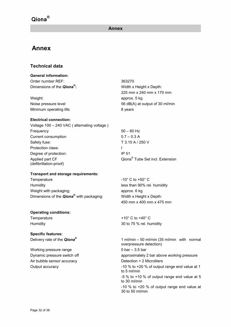
Technical data
General information:
Order number REF: 363270
Dimensions of the Qiona®: Width x Height x Depth:
225 mm x 240 mm x 170 mm
Weight: approx. 5 kg
Noise pressure level 56 dB(A) at output of 30 ml/min
Minimum operating life: 8 years
Electrical connection:
Voltage 100 – 240 VAC ( alternating voltage )
Frequency 50 – 60 Hz
Current consumption 0.7 – 0.3 A
Safety fuse: T 3.15 A / 250 V
Protection class: I
Degree of protection: IP 51
Applied part CF Qiona® Tube Set incl. Extension
(defibrillation-proof)
Transport and storage requirements:
Temperature -10° C to +50° C
Humidity less than 90% rel. humidity
Weight with packaging: approx. 6 kg
Dimensions of the Qiona® with packaging: Width x Height x Depth:
450 mm x 400 mm x 475 mm
Operating conditions:
Temperature +10° C to +40° C
Humidity 30 to 75 % rel. humidity
Specific features:
Delivery rate of the Qiona® 1 ml/min – 50 ml/min (35 ml/min with normal
overpressure detection)
Working pressure range 0 bar – 3.5 bar
Dynamic pressure switch off approximately 2 bar above working pressure
Air bubble sensor accuracy Detection > 2 Microliters
Output accuracy -10 % to +20 % of output range end value at 1 to 5 ml/min
-5 % to +10 % of output range end value at 5 to 30 ml/min
-10 % to +20 % of output range end value at 30 to 50 ml/min

Qiona®
Annex
Page 33 of 38
Electromagnetic emission
The Qiona® is suitable for operation in the specified electromagnetic environment. The customer and/or operator of the Qiona® must ensure that the device is used in the electromagnetic environment described below.
Measurement of emitted interference
Conformance Guidelines for the electromagnetic environment
High frequency emitted interference according to CISPR 11
Group 1
The Qiona® uses HF energy exclusively for its
internal functioning. Therefore, its high frequency emission is minimal and it is improbably that it will disturb nearby electronic devices.
High frequency emitted interference according to CISPR 11
Class B
The Qiona® is suitable for use in facilities
including living areas and areas that are directly connected to the public power supply that also supplies buildings used for living purposes.
Harmonic emittance acc. to IEC 61000-3-2
Not applicable
Voltage fluctuation/flicker emittance acc. to IEC 61000-3-3
Not applicable
Qiona®
Annex
Page 34 of 38
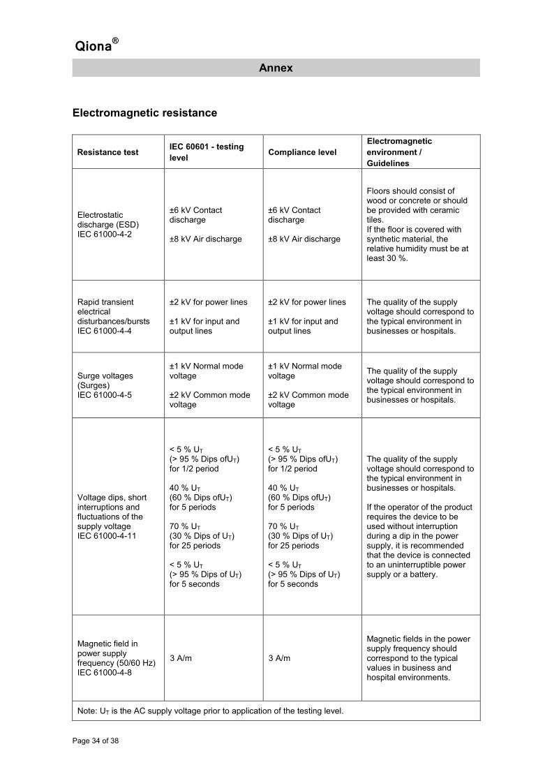
Electromagnetic resistance
Resistance test IEC 60601 - testing
level Compliance level
Electromagnetic
environment /
Guidelines
Electrostatic discharge (ESD) IEC 61000-4-2
±6 kV Contact discharge ±8 kV Air discharge
±6 kV Contact discharge ±8 kV Air discharge
Floors should consist of wood or concrete or should be provided with ceramic tiles. If the floor is covered with synthetic material, the relative humidity must be at least 30 %.
Rapid transient electrical disturbances/bursts IEC 61000-4-4
±2 kV for power lines ±1 kV for input and output lines
±2 kV for power lines ±1 kV for input and output lines
The quality of the supply voltage should correspond to the typical environment in businesses or hospitals.
Surge voltages (Surges) IEC 61000-4-5
±1 kV Normal mode voltage ±2 kV Common mode voltage
±1 kV Normal mode voltage ±2 kV Common mode voltage
The quality of the supply voltage should correspond to the typical environment in businesses or hospitals.
Voltage dips, short interruptions and fluctuations of the supply voltage IEC 61000-4-11
< 5 % UT (> 95 % Dips ofUT) for 1/2 period 40 % UT (60 % Dips ofUT) for 5 periods 70 % UT (30 % Dips of UT) for 25 periods < 5 % UT (> 95 % Dips of UT) for 5 seconds
< 5 % UT (> 95 % Dips ofUT) for 1/2 period 40 % UT (60 % Dips ofUT) for 5 periods 70 % UT (30 % Dips of UT) for 25 periods < 5 % UT (> 95 % Dips of UT) for 5 seconds
The quality of the supply voltage should correspond to the typical environment in businesses or hospitals. If the operator of the product requires the device to be used without interruption during a dip in the power supply, it is recommended that the device is connected to an uninterruptible power supply or a battery.
Magnetic field in power supply frequency (50/60 Hz) IEC 61000-4-8
3 A/m 3 A/m
Magnetic fields in the power supply frequency should correspond to the typical values in business and hospital environments.
Note: UT is the AC supply voltage prior to application of the testing level.
Qiona®
Annex
Page 35 of 38
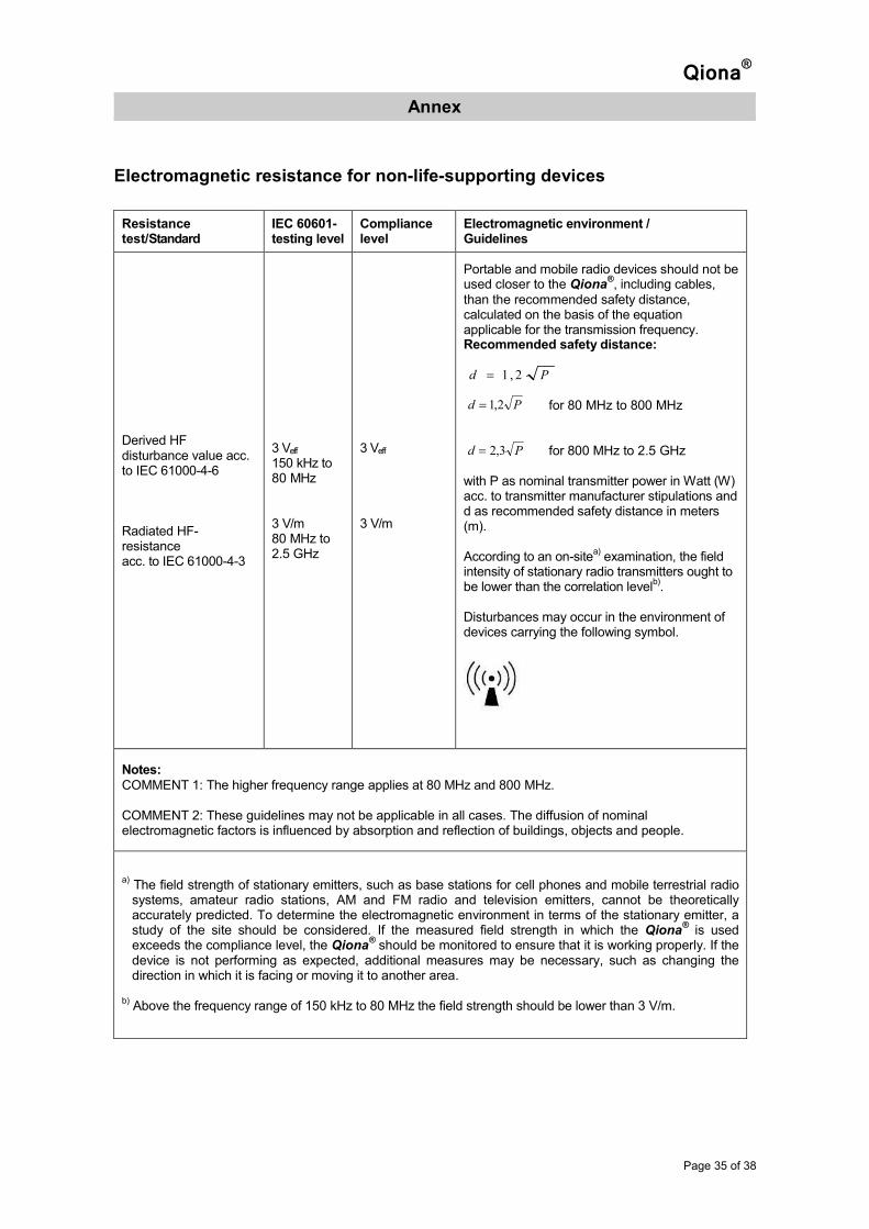
Electromagnetic resistance for non-life-supporting devices
Resistance test/Standard
IEC 60601- testing level
Compliance level
Electromagnetic environment / Guidelines
Derived HF disturbance value acc. to IEC 61000-4-6 Radiated HF-resistance acc. to IEC 61000-4-3
3 Veff 150 kHz to 80 MHz 3 V/m 80 MHz to 2.5 GHz
3 Veff 3 V/m
Portable and mobile radio devices should not be used closer to the Qiona
®, including cables,
than the recommended safety distance, calculated on the basis of the equation applicable for the transmission frequency. Recommended safety distance:
for 80 MHz to 800 MHz for 800 MHz to 2.5 GHz
with P as nominal transmitter power in Watt (W) acc. to transmitter manufacturer stipulations and d as recommended safety distance in meters (m). According to an on-site
a) examination, the field
intensity of stationary radio transmitters ought to be lower than the correlation level
b).
Disturbances may occur in the environment of devices carrying the following symbol.
Notes: COMMENT 1: The higher frequency range applies at 80 MHz and 800 MHz. COMMENT 2: These guidelines may not be applicable in all cases. The diffusion of nominal electromagnetic factors is influenced by absorption and reflection of buildings, objects and people.
a) The field strength of stationary emitters, such as base stations for cell phones and mobile terrestrial radio systems, amateur radio stations, AM and FM radio and television emitters, cannot be theoretically accurately predicted. To determine the electromagnetic environment in terms of the stationary emitter, a study of the site should be considered. If the measured field strength in which the Qiona
® is used
exceeds the compliance level, the Qiona® should be monitored to ensure that it is working properly. If the
device is not performing as expected, additional measures may be necessary, such as changing the direction in which it is facing or moving it to another area. b) Above the frequency range of 150 kHz to 80 MHz the field strength should be lower than 3 V/m.
Pd 3,2=
Pd 2,1=
Pd 2,1=

Qiona®
Annex
Page 36 of 38
Recommended safety distances
Recommended safety distances between portable and mobile HF telecommunications devices and the Qiona
®
The Qiona® is designed for use in an electromagnetic environment where the high frequency disturbance
is controlled. The customer or user of the Qiona® can help to prevent electromagnetic disturbance by
observing the minimum distance between portable and mobile HF telecommunications devices (emitters) and the Qiona
® regardless of the output of the communication device, as indicated below.
Capacity transmitter performance
(W)
Safety distance dependent on transmission frequency (m)
150 kHz to 80 MHz
80 MHz to 800 MHz
800 MHz to 2.5 GHz
0.01 0.12 0.12 0.23
0.1 0.37 0.37 0.74
1 1.2 1.2 2.3
10 3.7 3.7 7.4
100 12 12 23
Pd 2,1= Pd 3,2=Pd 2,1=

Qiona®
Annex
Page 37 of 38
Accessories
• Qiona® Tube Set incl. Extension REF: 365775 Weight: 90 g Overall length Extension: 1.5 m Total length tube: 3 m Length between Qiona® and catheter adapter: 3 m (1.5 m tube + 1.5 m extension)
• Qiona® Foot Switch REF: 365773 Weight: 380 g Cable length: 5 m
• Qiona® AutoFlow Sensor REF: 365774 Weight: 200 g Cable length: 4 m
• Qiona® Pole Adapter Set REF: 377184 Weight: 25 g

Current revision 2011-04 D Software version FwM 1.04. FwW 1.02
Guidelines 93/42 EEC
Manufacturer: Distributor: Möller Medical GmbH BIOTRONIK SE & Co. KG Wasserkuppenstrasse 29-31 Woermannkehre 1 D – 36043 Fulda D – 12359 Berlin Tel. +49 (0) 661 / 94 19 5 – 0 Tel. +49 (0) 30 68905-0 Fax +49 (0) 661 / 94 19 5 – 90 Fax +49 (0) 30 68440-60 http://www.moeller-medical.com www.biotronik.com [email protected] [email protected]
1275 Operating instructions order number (REF) 367545