300 ALIGNMENT CHAPTER - British Columbia · BC MoT SUPPLEMENT TO TAC GEOMETRIC DESIGN GUIDE MoT...
18
BC MoT SUPPLEMENT TO TAC GEOMETRIC DESIGN GUIDE MoT Section 300 TAC Section Chapter 2 June, 2007 Page 300-i 300 ALIGNMENT CHAPTER 330 HORIZONTAL AND VERTICAL ALIGNMENT 330.01 Circular Curves .................................................................................... 330-1 330.02 Spiral Curves........................................................................................ 330-5 330.03 Crest Vertical Curve ............................................................................ 330-6 330.04 Vertical and Horizontal Alignments Near and On Bridges ................. 330-7 340 GEOMETRIC DESIGN AIDS 300 ALIGNMENT CHAPTER TABLES 330.A Minimum Radii for Rural Design ................................................................. 330-1 330.B Superelevation Calculation Factors .............................................................. 330-2 330.C Maximum Superelevation for Auxiliary Truck Climbing Lanes .................. 330-2 330.D Superelevation and Spiral Lengths E max = 0.06 m/m.................................... 330-3 330.E Superelevation and Spiral Lengths E max = 0.08 m/m.................................... 330-4 330.F Minimum K Factors to Provide Stopping Sight Distance on Crest Curves.. 330-6 300 ALIGNMENT CHAPTER FIGURES 340.A Spiral and Circular Curve Nomenclature...................................................... 340-1 340.B Spiral Formulae............................................................................................. 340-2 340.C Circular Curve with Equal Spirals ................................................................ 340-3 340.D Circular Curve with Unequal Spirals ............................................................ 340-4 340.E Three Transition Compound Curve – General Layout ................................. 340-5 340.F Three Transition Compound Curve – Segmental Spiral ............................... 340-6 340.G Three Transition Compound Curve Calculation ........................................... 340-7
Transcript of 300 ALIGNMENT CHAPTER - British Columbia · BC MoT SUPPLEMENT TO TAC GEOMETRIC DESIGN GUIDE MoT...

BC MoT SUPPLEMENT TO TAC GEOMETRIC DESIGN GUIDE MoT Section 300 TAC Section Chapter 2
June, 2007 Page 300-i
300 ALIGNMENT CHAPTER 330 HORIZONTAL AND VERTICAL ALIGNMENT
330.01 Circular Curves .................................................................................... 330-1 330.02 Spiral Curves........................................................................................ 330-5 330.03 Crest Vertical Curve ............................................................................ 330-6 330.04 Vertical and Horizontal Alignments Near and On Bridges ................. 330-7
340 GEOMETRIC DESIGN AIDS
300 ALIGNMENT CHAPTER TABLES
330.A Minimum Radii for Rural Design ................................................................. 330-1
330.B Superelevation Calculation Factors .............................................................. 330-2
330.C Maximum Superelevation for Auxiliary Truck Climbing Lanes.................. 330-2
330.D Superelevation and Spiral Lengths Emax = 0.06 m/m.................................... 330-3
330.E Superelevation and Spiral Lengths Emax = 0.08 m/m.................................... 330-4
330.F Minimum K Factors to Provide Stopping Sight Distance on Crest Curves.. 330-6
300 ALIGNMENT CHAPTER FIGURES
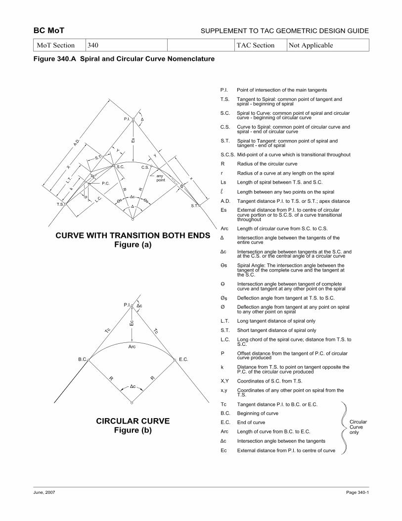
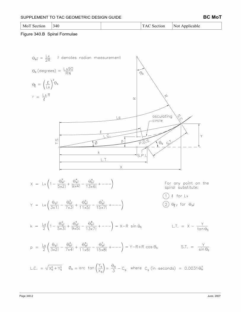
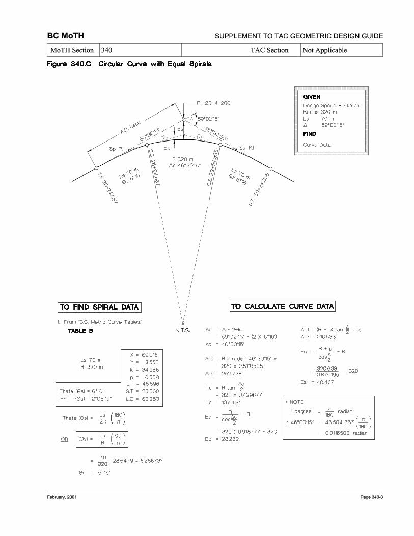
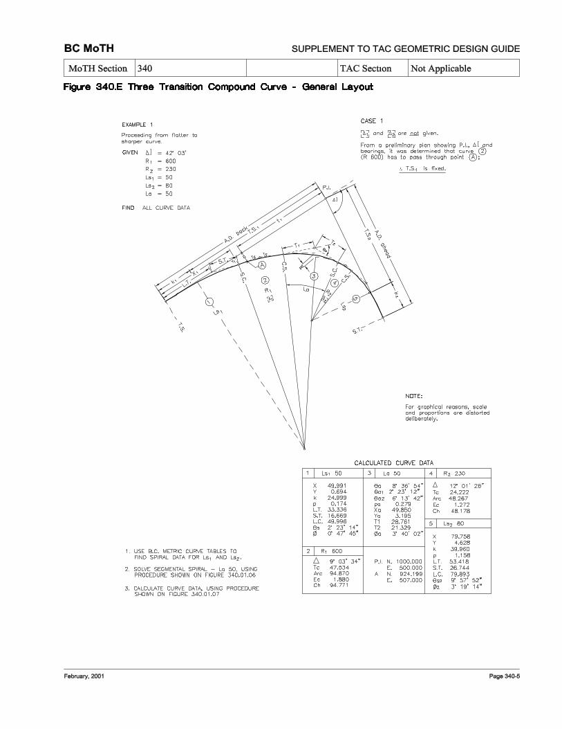
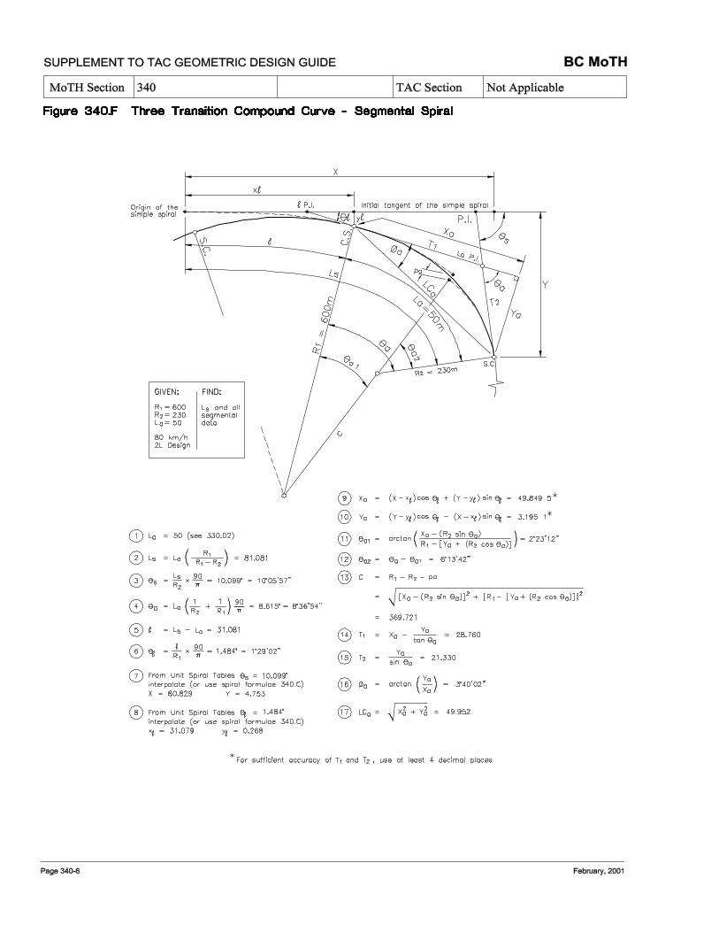
340.A Spiral and Circular Curve Nomenclature...................................................... 340-1 340.B Spiral Formulae............................................................................................. 340-2 340.C Circular Curve with Equal Spirals ................................................................ 340-3 340.D Circular Curve with Unequal Spirals............................................................ 340-4 340.E Three Transition Compound Curve – General Layout ................................. 340-5 340.F Three Transition Compound Curve – Segmental Spiral............................... 340-6 340.G Three Transition Compound Curve Calculation........................................... 340-7

SUPPLEMENT TO TAC GEOMETRIC DESIGN GUIDE BC MoT MoT Section 300 TAC Section Chapter 2
Page 300-ii June, 2007
This page is intentionally left blank
BC MoT SUPPLEMENT TO TAC GEOMETRIC DESIGN GUIDE MoT Section 330 TAC Section Chapter 2.1
June, 2007 Page 330-1
330 HORIZONTAL AND VERTICAL ALIGNMENT
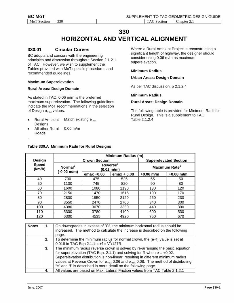
330.01 Circular Curves BC adopts and concurs with the engineering principles and discussion throughout Section 2.1.2.1 of TAC. However, we wish to supplement the Tables provided with MoT specific procedures and recommended guidelines. Maximum Superelevation
Rural Areas: Design Domain As stated in TAC, 0.06 m/m is the preferred maximum superelevation. The following guidelines indicate the MoT recommendations in the selection of Design emax values. • Rural Ambient
Designs Match existing emax
• All other Rural Roads
0.06 m/m
.
Where a Rural Ambient Project is reconstructing a significant length of highway, the designer should consider using 0.06 m/m as maximum superelevation. Minimum Radius
Urban Areas: Design Domain As per TAC discussion, p 2.1.2.4 Minimum Radius
Rural Areas: Design Domain The following table is provided for Minimum Radii for Rural Design. This is a supplement to TAC Table 2.1.2.4
Table 330.A Minimum Radii for Rural Designs
Minimum Radius (m) Crown Section Superelevated Section
Reverse3 (0.02 m/m) Maximum Rate1
Design Speed (km/h) Normal2
(-0.02 m/m) emax +0.06 emax + 0.08 +0.06 m/m +0.08 m/m 40 700 475 525 55 50 50 1100 745 820 90 80 60 1600 1080 1190 130 120 70 2150 1470 1615 190 170 80 2800 1950 2120 250 230 90 3550 2470 2700 340 300
100 4380 3070 3350 440 390 110 5300 3780 4100 600 530 120 6300 4535 4920 750 670
Notes 1. On downgrades in excess of 3%, the minimum horizontal radius should be
increased. The method to calculate the increase is described on the following page.
2. To determine the minimum radius for normal crown, the (e+f) value is set at 0.018 in TAC Eqn 2.1.1: e+f = V2/127R.
3. The minimum radius reverse crown is solved by re-arranging the basic equation for superelevation (TAC Eqn. 2.1.1) and solving for R when e = +0.02. Superelevation distribution is non-linear, resulting in different minimum radius values at Reverse Crown for emax 0.06 and emax 0.08. The method of distributing “e” and “f” is described in more detail on the following page.
4. All values are based on Max. Lateral Friction values from TAC Table 2.1.2.1
SUPPLEMENT TO TAC GEOMETRIC DESIGN GUIDE BC MoT MoT Section 330 TAC Section Chapter 2.1
Page 330-2 June, 2007
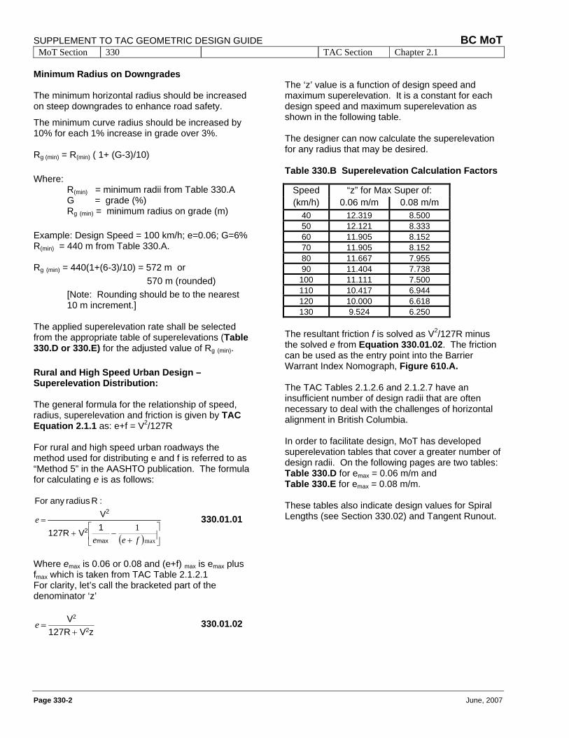
Minimum Radius on Downgrades The minimum horizontal radius should be increased on steep downgrades to enhance road safety.
The minimum curve radius should be increased by 10% for each 1% increase in grade over 3%. Rg (min) = R(min) ( 1+ (G-3)/10) Where:
R(min) = minimum radii from Table 330.A G = grade (%) Rg (min) = minimum radius on grade (m)
Example: Design Speed = 100 km/h; e=0.06; G=6% R(min) = 440 m from Table 330.A. Rg (min) = 440(1+(6-3)/10) = 572 m or
570 m (rounded) [Note: Rounding should be to the nearest 10 m increment.]
The applied superelevation rate shall be selected from the appropriate table of superelevations (Table 330.D or 330.E) for the adjusted value of Rg (min). Rural and High Speed Urban Design – Superelevation Distribution: The general formula for the relationship of speed, radius, superelevation and friction is given by TAC Equation 2.1.1 as: e+f = V2/127R For rural and high speed urban roadways the method used for distributing e and f is referred to as “Method 5” in the AASHTO publication. The formula for calculating e is as follows:
( ) ⎥⎦
⎤⎢⎣
⎡+
−+=
max
1fee
e
max2
2
1V 127R
V
:R radius any For
330.01.01
Where emax is 0.06 or 0.08 and (e+f) max is emax plus fmax which is taken from TAC Table 2.1.2.1 For clarity, let’s call the bracketed part of the denominator ‘z’
zV 127RV
2
2
+=e 330.01.02
The ‘z’ value is a function of design speed and maximum superelevation. It is a constant for each design speed and maximum superelevation as shown in the following table. The designer can now calculate the superelevation for any radius that may be desired. Table 330.B Superelevation Calculation Factors
Speed “z” for Max Super of: (km/h) 0.06 m/m 0.08 m/m
40 12.319 8.500 50 12.121 8.333 60 11.905 8.152 70 11.905 8.152 80 11.667 7.955 90 11.404 7.738
100 11.111 7.500 110 10.417 6.944 120 10.000 6.618 130 9.524 6.250
The resultant friction f is solved as V2/127R minus the solved e from Equation 330.01.02. The friction can be used as the entry point into the Barrier Warrant Index Nomograph, Figure 610.A. The TAC Tables 2.1.2.6 and 2.1.2.7 have an insufficient number of design radii that are often necessary to deal with the challenges of horizontal alignment in British Columbia. In order to facilitate design, MoT has developed superelevation tables that cover a greater number of design radii. On the following pages are two tables: Table 330.D for emax = 0.06 m/m and Table 330.E for emax = 0.08 m/m. These tables also indicate design values for Spiral Lengths (see Section 330.02) and Tangent Runout.
BC MoT SUPPLEMENT TO TAC GEOMETRIC DESIGN GUIDE MoT Section 330 TAC Section Chapter 2.1
June, 2007 Page 330-3
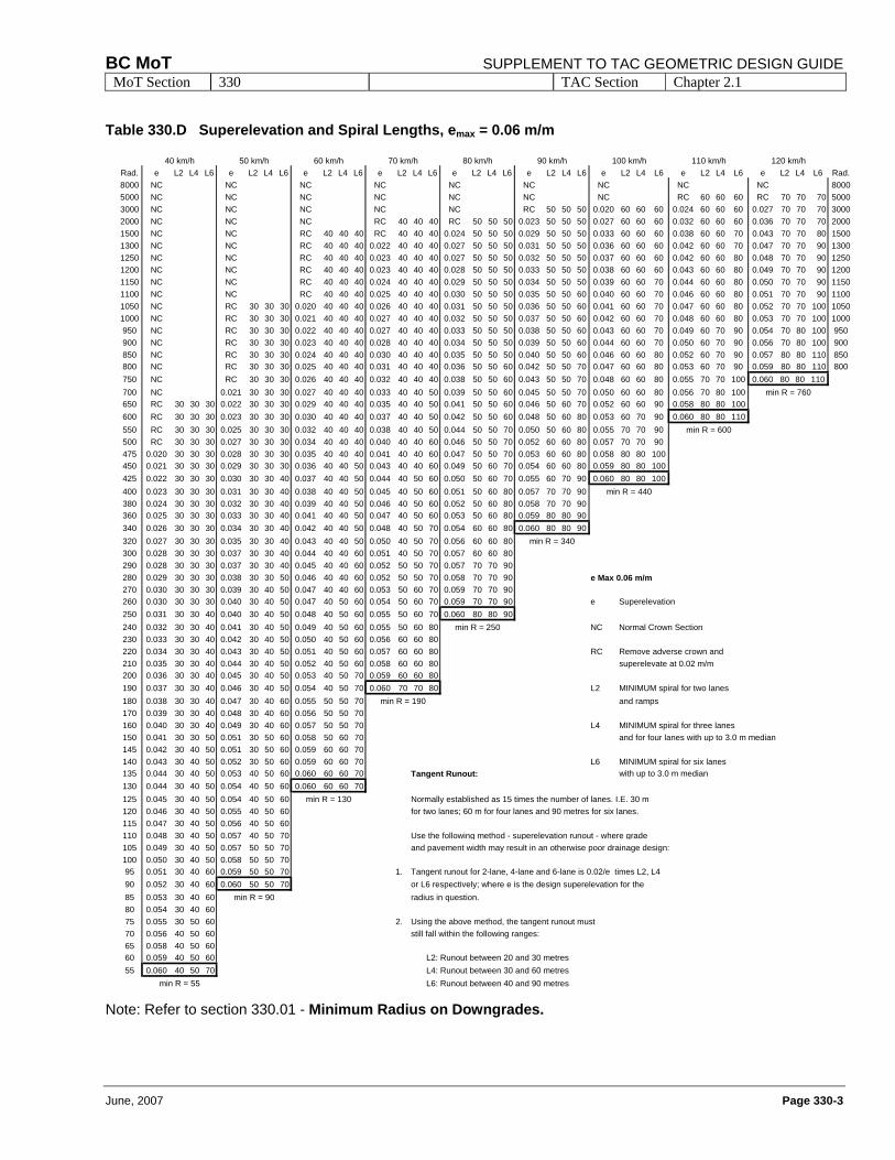
Table 330.D Superelevation and Spiral Lengths, emax = 0.06 m/m
Note: Refer to section 330.01 - Minimum Radius on Downgrades.
40 km/h 50 km/h 60 km/h 70 km/h 80 km/h 90 km/h 100 km/h 110 km/h 120 km/hRad. e L2 L4 L6 e L2 L4 L6 e L2 L4 L6 e L2 L4 L6 e L2 L4 L6 e L2 L4 L6 e L2 L4 L6 e L2 L4 L6 e L2 L4 L6 Rad.8000 NC NC NC NC NC NC NC NC NC 80005000 NC NC NC NC NC NC NC RC 60 60 60 RC 70 70 70 50003000 NC NC NC NC NC RC 50 50 50 0.020 60 60 60 0.024 60 60 60 0.027 70 70 70 30002000 NC NC NC RC 40 40 40 RC 50 50 50 0.023 50 50 50 0.027 60 60 60 0.032 60 60 60 0.036 70 70 70 20001500 NC NC RC 40 40 40 RC 40 40 40 0.024 50 50 50 0.029 50 50 50 0.033 60 60 60 0.038 60 60 70 0.043 70 70 80 15001300 NC NC RC 40 40 40 0.022 40 40 40 0.027 50 50 50 0.031 50 50 50 0.036 60 60 60 0.042 60 60 70 0.047 70 70 90 13001250 NC NC RC 40 40 40 0.023 40 40 40 0.027 50 50 50 0.032 50 50 50 0.037 60 60 60 0.042 60 60 80 0.048 70 70 90 12501200 NC NC RC 40 40 40 0.023 40 40 40 0.028 50 50 50 0.033 50 50 50 0.038 60 60 60 0.043 60 60 80 0.049 70 70 90 12001150 NC NC RC 40 40 40 0.024 40 40 40 0.029 50 50 50 0.034 50 50 50 0.039 60 60 70 0.044 60 60 80 0.050 70 70 90 11501100 NC NC RC 40 40 40 0.025 40 40 40 0.030 50 50 50 0.035 50 50 60 0.040 60 60 70 0.046 60 60 80 0.051 70 70 90 11001050 NC RC 30 30 30 0.020 40 40 40 0.026 40 40 40 0.031 50 50 50 0.036 50 50 60 0.041 60 60 70 0.047 60 60 80 0.052 70 70 100 10501000 NC RC 30 30 30 0.021 40 40 40 0.027 40 40 40 0.032 50 50 50 0.037 50 50 60 0.042 60 60 70 0.048 60 60 80 0.053 70 70 100 1000950 NC RC 30 30 30 0.022 40 40 40 0.027 40 40 40 0.033 50 50 50 0.038 50 50 60 0.043 60 60 70 0.049 60 70 90 0.054 70 80 100 950900 NC RC 30 30 30 0.023 40 40 40 0.028 40 40 40 0.034 50 50 50 0.039 50 50 60 0.044 60 60 70 0.050 60 70 90 0.056 70 80 100 900850 NC RC 30 30 30 0.024 40 40 40 0.030 40 40 40 0.035 50 50 50 0.040 50 50 60 0.046 60 60 80 0.052 60 70 90 0.057 80 80 110 850800 NC RC 30 30 30 0.025 40 40 40 0.031 40 40 40 0.036 50 50 60 0.042 50 50 70 0.047 60 60 80 0.053 60 70 90 0.059 80 80 110 800750 NC RC 30 30 30 0.026 40 40 40 0.032 40 40 40 0.038 50 50 60 0.043 50 50 70 0.048 60 60 80 0.055 70 70 100 0.060 80 80 110700 NC 0.021 30 30 30 0.027 40 40 40 0.033 40 40 50 0.039 50 50 60 0.045 50 50 70 0.050 60 60 80 0.056 70 80 100 min R = 760650 RC 30 30 30 0.022 30 30 30 0.029 40 40 40 0.035 40 40 50 0.041 50 50 60 0.046 50 60 70 0.052 60 60 90 0.058 80 80 100600 RC 30 30 30 0.023 30 30 30 0.030 40 40 40 0.037 40 40 50 0.042 50 50 60 0.048 50 60 80 0.053 60 70 90 0.060 80 80 110550 RC 30 30 30 0.025 30 30 30 0.032 40 40 40 0.038 40 40 50 0.044 50 50 70 0.050 50 60 80 0.055 70 70 90 min R = 600500 RC 30 30 30 0.027 30 30 30 0.034 40 40 40 0.040 40 40 60 0.046 50 50 70 0.052 60 60 80 0.057 70 70 90475 0.020 30 30 30 0.028 30 30 30 0.035 40 40 40 0.041 40 40 60 0.047 50 50 70 0.053 60 60 80 0.058 80 80 100450 0.021 30 30 30 0.029 30 30 30 0.036 40 40 50 0.043 40 40 60 0.049 50 60 70 0.054 60 60 80 0.059 80 80 100425 0.022 30 30 30 0.030 30 30 40 0.037 40 40 50 0.044 40 50 60 0.050 50 60 70 0.055 60 70 90 0.060 80 80 100400 0.023 30 30 30 0.031 30 30 40 0.038 40 40 50 0.045 40 50 60 0.051 50 60 80 0.057 70 70 90 min R = 440380 0.024 30 30 30 0.032 30 30 40 0.039 40 40 50 0.046 40 50 60 0.052 50 60 80 0.058 70 70 90360 0.025 30 30 30 0.033 30 30 40 0.041 40 40 50 0.047 40 50 60 0.053 50 60 80 0.059 80 80 90340 0.026 30 30 30 0.034 30 30 40 0.042 40 40 50 0.048 40 50 70 0.054 60 60 80 0.060 80 80 90320 0.027 30 30 30 0.035 30 30 40 0.043 40 40 50 0.050 40 50 70 0.056 60 60 80 min R = 340300 0.028 30 30 30 0.037 30 30 40 0.044 40 40 60 0.051 40 50 70 0.057 60 60 80290 0.028 30 30 30 0.037 30 30 40 0.045 40 40 60 0.052 50 50 70 0.057 70 70 90280 0.029 30 30 30 0.038 30 30 50 0.046 40 40 60 0.052 50 50 70 0.058 70 70 90 e Max 0.06 m/m270 0.030 30 30 30 0.039 30 40 50 0.047 40 40 60 0.053 50 60 70 0.059 70 70 90260 0.030 30 30 30 0.040 30 40 50 0.047 40 50 60 0.054 50 60 70 0.059 70 70 90 e Superelevation250 0.031 30 30 40 0.040 30 40 50 0.048 40 50 60 0.055 50 60 70 0.060 80 80 90240 0.032 30 30 40 0.041 30 40 50 0.049 40 50 60 0.055 50 60 80 min R = 250 NC Normal Crown Section230 0.033 30 30 40 0.042 30 40 50 0.050 40 50 60 0.056 60 60 80220 0.034 30 30 40 0.043 30 40 50 0.051 40 50 60 0.057 60 60 80 RC Remove adverse crown and210 0.035 30 30 40 0.044 30 40 50 0.052 40 50 60 0.058 60 60 80 superelevate at 0.02 m/m200 0.036 30 30 40 0.045 30 40 50 0.053 40 50 70 0.059 60 60 80190 0.037 30 30 40 0.046 30 40 50 0.054 40 50 70 0.060 70 70 80 L2 MINIMUM spiral for two lanes180 0.038 30 30 40 0.047 30 40 60 0.055 50 50 70 min R = 190 and ramps170 0.039 30 30 40 0.048 30 40 60 0.056 50 50 70160 0.040 30 30 40 0.049 30 40 60 0.057 50 50 70 L4 MINIMUM spiral for three lanes150 0.041 30 30 50 0.051 30 50 60 0.058 50 60 70 and for four lanes with up to 3.0 m median145 0.042 30 40 50 0.051 30 50 60 0.059 60 60 70140 0.043 30 40 50 0.052 30 50 60 0.059 60 60 70 L6 MINIMUM spiral for six lanes135 0.044 30 40 50 0.053 40 50 60 0.060 60 60 70 Tangent Runout: with up to 3.0 m median130 0.044 30 40 50 0.054 40 50 60 0.060 60 60 70125 0.045 30 40 50 0.054 40 50 60 min R = 130 Normally established as 15 times the number of lanes. I.E. 30 m120 0.046 30 40 50 0.055 40 50 60 for two lanes; 60 m for four lanes and 90 metres for six lanes.115 0.047 30 40 50 0.056 40 50 60110 0.048 30 40 50 0.057 40 50 70 Use the following method - superelevation runout - where grade105 0.049 30 40 50 0.057 50 50 70 and pavement width may result in an otherwise poor drainage design:100 0.050 30 40 50 0.058 50 50 7095 0.051 30 40 60 0.059 50 50 70 1. Tangent runout for 2-lane, 4-lane and 6-lane is 0.02/e times L2, L490 0.052 30 40 60 0.060 50 50 70 or L6 respectively; where e is the design superelevation for the85 0.053 30 40 60 min R = 90 radius in question.80 0.054 30 40 6075 0.055 30 50 60 2. Using the above method, the tangent runout must 70 0.056 40 50 60 still fall within the following ranges:65 0.058 40 50 6060 0.059 40 50 60 L2: Runout between 20 and 30 metres55 0.060 40 50 70 L4: Runout between 30 and 60 metres
min R = 55 L6: Runout between 40 and 90 metres
SUPPLEMENT TO TAC GEOMETRIC DESIGN GUIDE BC MoT MoT Section 330 TAC Section Chapter 2.1
Page 330-4 June, 2007
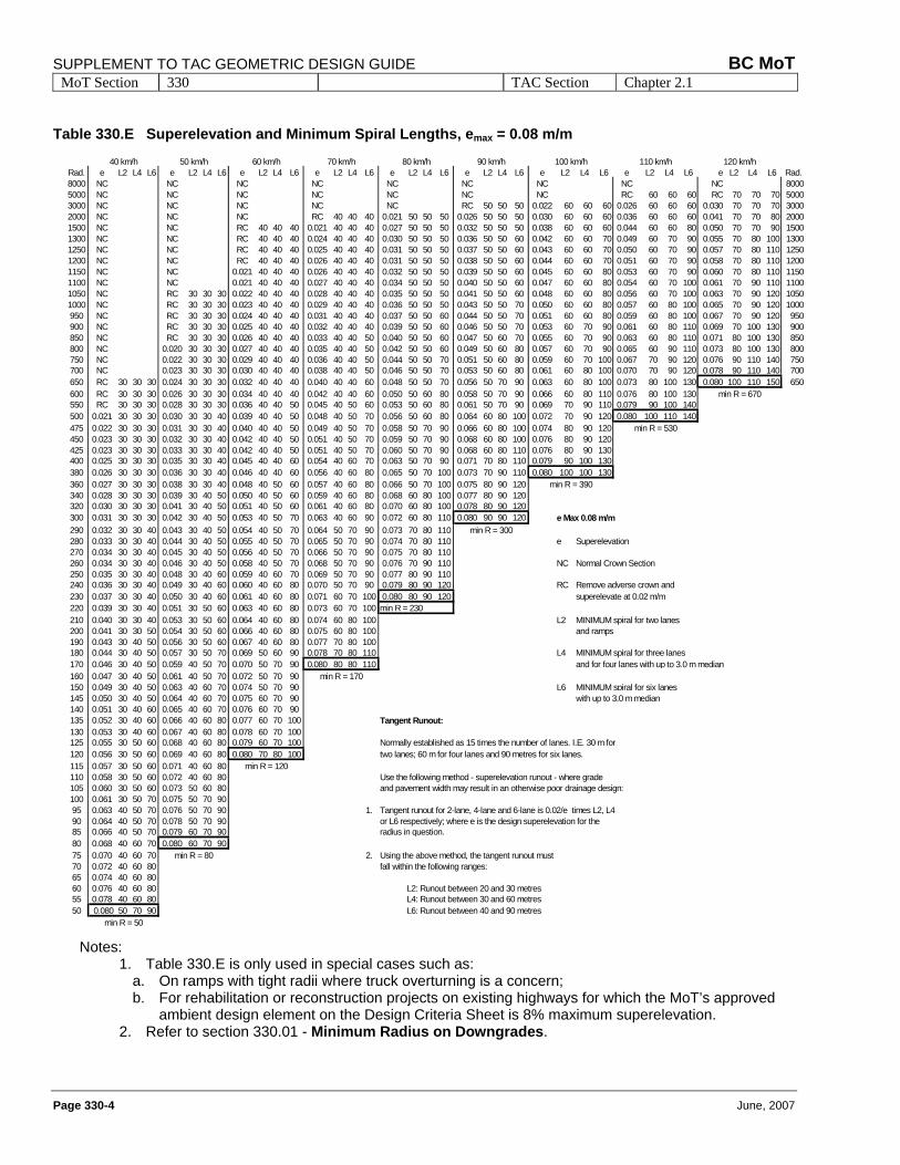
Table 330.E Superelevation and Minimum Spiral Lengths, emax = 0.08 m/m
Notes: 1. Table 330.E is only used in special cases such as:
a. On ramps with tight radii where truck overturning is a concern; b. For rehabilitation or reconstruction projects on existing highways for which the MoT’s approved
ambient design element on the Design Criteria Sheet is 8% maximum superelevation. 2. Refer to section 330.01 - Minimum Radius on Downgrades.
40 km/h 50 km/h 60 km/h 70 km/h 80 km/h 90 km/h 100 km/h 110 km/h 120 km/hRad. e L2 L4 L6 e L2 L4 L6 e L2 L4 L6 e L2 L4 L6 e L2 L4 L6 e L2 L4 L6 e L2 L4 L6 e L2 L4 L6 e L2 L4 L6 Rad.8000 NC NC NC NC NC NC NC NC NC 80005000 NC NC NC NC NC NC NC RC 60 60 60 RC 70 70 70 50003000 NC NC NC NC NC RC 50 50 50 0.022 60 60 60 0.026 60 60 60 0.030 70 70 70 30002000 NC NC NC RC 40 40 40 0.021 50 50 50 0.026 50 50 50 0.030 60 60 60 0.036 60 60 60 0.041 70 70 80 20001500 NC NC RC 40 40 40 0.021 40 40 40 0.027 50 50 50 0.032 50 50 50 0.038 60 60 60 0.044 60 60 80 0.050 70 70 90 15001300 NC NC RC 40 40 40 0.024 40 40 40 0.030 50 50 50 0.036 50 50 60 0.042 60 60 70 0.049 60 70 90 0.055 70 80 100 13001250 NC NC RC 40 40 40 0.025 40 40 40 0.031 50 50 50 0.037 50 50 60 0.043 60 60 70 0.050 60 70 90 0.057 70 80 110 12501200 NC NC RC 40 40 40 0.026 40 40 40 0.031 50 50 50 0.038 50 50 60 0.044 60 60 70 0.051 60 70 90 0.058 70 80 110 12001150 NC NC 0.021 40 40 40 0.026 40 40 40 0.032 50 50 50 0.039 50 50 60 0.045 60 60 80 0.053 60 70 90 0.060 70 80 110 11501100 NC NC 0.021 40 40 40 0.027 40 40 40 0.034 50 50 50 0.040 50 50 60 0.047 60 60 80 0.054 60 70 100 0.061 70 90 110 11001050 NC RC 30 30 30 0.022 40 40 40 0.028 40 40 40 0.035 50 50 50 0.041 50 50 60 0.048 60 60 80 0.056 60 70 100 0.063 70 90 120 10501000 NC RC 30 30 30 0.023 40 40 40 0.029 40 40 40 0.036 50 50 50 0.043 50 50 70 0.050 60 60 80 0.057 60 80 100 0.065 70 90 120 1000950 NC RC 30 30 30 0.024 40 40 40 0.031 40 40 40 0.037 50 50 60 0.044 50 50 70 0.051 60 60 80 0.059 60 80 100 0.067 70 90 120 950900 NC RC 30 30 30 0.025 40 40 40 0.032 40 40 40 0.039 50 50 60 0.046 50 50 70 0.053 60 70 90 0.061 60 80 110 0.069 70 100 130 900850 NC RC 30 30 30 0.026 40 40 40 0.033 40 40 50 0.040 50 50 60 0.047 50 60 70 0.055 60 70 90 0.063 60 80 110 0.071 80 100 130 850800 NC 0.020 30 30 30 0.027 40 40 40 0.035 40 40 50 0.042 50 50 60 0.049 50 60 80 0.057 60 70 90 0.065 60 90 110 0.073 80 100 130 800750 NC 0.022 30 30 30 0.029 40 40 40 0.036 40 40 50 0.044 50 50 70 0.051 50 60 80 0.059 60 70 100 0.067 70 90 120 0.076 90 110 140 750700 NC 0.023 30 30 30 0.030 40 40 40 0.038 40 40 50 0.046 50 50 70 0.053 50 60 80 0.061 60 80 100 0.070 70 90 120 0.078 90 110 140 700650 RC 30 30 30 0.024 30 30 30 0.032 40 40 40 0.040 40 40 60 0.048 50 50 70 0.056 50 70 90 0.063 60 80 100 0.073 80 100 130 0.080 100 110 150 650600 RC 30 30 30 0.026 30 30 30 0.034 40 40 40 0.042 40 40 60 0.050 50 60 80 0.058 50 70 90 0.066 60 80 110 0.076 80 100 130 min R = 670550 RC 30 30 30 0.028 30 30 30 0.036 40 40 50 0.045 40 50 60 0.053 50 60 80 0.061 50 70 90 0.069 70 90 110 0.079 90 100 140500 0.021 30 30 30 0.030 30 30 40 0.039 40 40 50 0.048 40 50 70 0.056 50 60 80 0.064 60 80 100 0.072 70 90 120 0.080 100 110 140475 0.022 30 30 30 0.031 30 30 40 0.040 40 40 50 0.049 40 50 70 0.058 50 70 90 0.066 60 80 100 0.074 80 90 120 min R = 530450 0.023 30 30 30 0.032 30 30 40 0.042 40 40 50 0.051 40 50 70 0.059 50 70 90 0.068 60 80 100 0.076 80 90 120425 0.023 30 30 30 0.033 30 30 40 0.042 40 40 50 0.051 40 50 70 0.060 50 70 90 0.068 60 80 110 0.076 80 90 130400 0.025 30 30 30 0.035 30 30 40 0.045 40 40 60 0.054 40 60 70 0.063 50 70 90 0.071 70 80 110 0.079 90 100 130380 0.026 30 30 30 0.036 30 30 40 0.046 40 40 60 0.056 40 60 80 0.065 50 70 100 0.073 70 90 110 0.080 100 100 130360 0.027 30 30 30 0.038 30 30 40 0.048 40 50 60 0.057 40 60 80 0.066 50 70 100 0.075 80 90 120 min R = 390340 0.028 30 30 30 0.039 30 40 50 0.050 40 50 60 0.059 40 60 80 0.068 60 80 100 0.077 80 90 120320 0.030 30 30 30 0.041 30 40 50 0.051 40 50 60 0.061 40 60 80 0.070 60 80 100 0.078 80 90 120300 0.031 30 30 30 0.042 30 40 50 0.053 40 50 70 0.063 40 60 90 0.072 60 80 110 0.080 90 90 120 e Max 0.08 m/m290 0.032 30 30 40 0.043 30 40 50 0.054 40 50 70 0.064 50 70 90 0.073 70 80 110 min R = 300280 0.033 30 30 40 0.044 30 40 50 0.055 40 50 70 0.065 50 70 90 0.074 70 80 110 e Superelevation270 0.034 30 30 40 0.045 30 40 50 0.056 40 50 70 0.066 50 70 90 0.075 70 80 110260 0.034 30 30 40 0.046 30 40 50 0.058 40 50 70 0.068 50 70 90 0.076 70 90 110 NC Normal Crown Section250 0.035 30 30 40 0.048 30 40 60 0.059 40 60 70 0.069 50 70 90 0.077 80 90 110240 0.036 30 30 40 0.049 30 40 60 0.060 40 60 80 0.070 50 70 90 0.079 80 90 120 RC Remove adverse crown and230 0.037 30 30 40 0.050 30 40 60 0.061 40 60 80 0.071 60 70 100 0.080 80 90 120 superelevate at 0.02 m/m220 0.039 30 30 40 0.051 30 50 60 0.063 40 60 80 0.073 60 70 100 min R = 230210 0.040 30 30 40 0.053 30 50 60 0.064 40 60 80 0.074 60 80 100 L2 MINIMUM spiral for two lanes200 0.041 30 30 50 0.054 30 50 60 0.066 40 60 80 0.075 60 80 100 and ramps190 0.043 30 40 50 0.056 30 50 60 0.067 40 60 80 0.077 70 80 100180 0.044 30 40 50 0.057 30 50 70 0.069 50 60 90 0.078 70 80 110 L4 MINIMUM spiral for three lanes170 0.046 30 40 50 0.059 40 50 70 0.070 50 70 90 0.080 80 80 110 and for four lanes with up to 3.0 m median160 0.047 30 40 50 0.061 40 50 70 0.072 50 70 90 min R = 170150 0.049 30 40 50 0.063 40 60 70 0.074 50 70 90 L6 MINIMUM spiral for six lanes145 0.050 30 40 50 0.064 40 60 70 0.075 60 70 90 with up to 3.0 m median140 0.051 30 40 60 0.065 40 60 70 0.076 60 70 90135 0.052 30 40 60 0.066 40 60 80 0.077 60 70 100 Tangent Runout:130 0.053 30 40 60 0.067 40 60 80 0.078 60 70 100125 0.055 30 50 60 0.068 40 60 80 0.079 60 70 100 Normally established as 15 times the number of lanes. I.E. 30 m for120 0.056 30 50 60 0.069 40 60 80 0.080 70 80 100 two lanes; 60 m for four lanes and 90 metres for six lanes.115 0.057 30 50 60 0.071 40 60 80 min R = 120110 0.058 30 50 60 0.072 40 60 80 Use the following method - superelevation runout - where grade105 0.060 30 50 60 0.073 50 60 80 and pavement width may result in an otherwise poor drainage design:100 0.061 30 50 70 0.075 50 70 9095 0.063 40 50 70 0.076 50 70 90 1. Tangent runout for 2-lane, 4-lane and 6-lane is 0.02/e times L2, L490 0.064 40 50 70 0.078 50 70 90 or L6 respectively; where e is the design superelevation for the85 0.066 40 50 70 0.079 60 70 90 radius in question.80 0.068 40 60 70 0.080 60 70 9075 0.070 40 60 70 min R = 80 2. Using the above method, the tangent runout must 70 0.072 40 60 80 fall within the following ranges:65 0.074 40 60 8060 0.076 40 60 80 L2: Runout between 20 and 30 metres55 0.078 40 60 80 L4: Runout between 30 and 60 metres50 0.080 50 70 90 L6: Runout between 40 and 90 metres
min R = 50
BC MoT SUPPLEMENT TO TAC GEOMETRIC DESIGN GUIDE MoT Section 330 TAC Section Chapter 2.1
June, 2007 Page 330-5
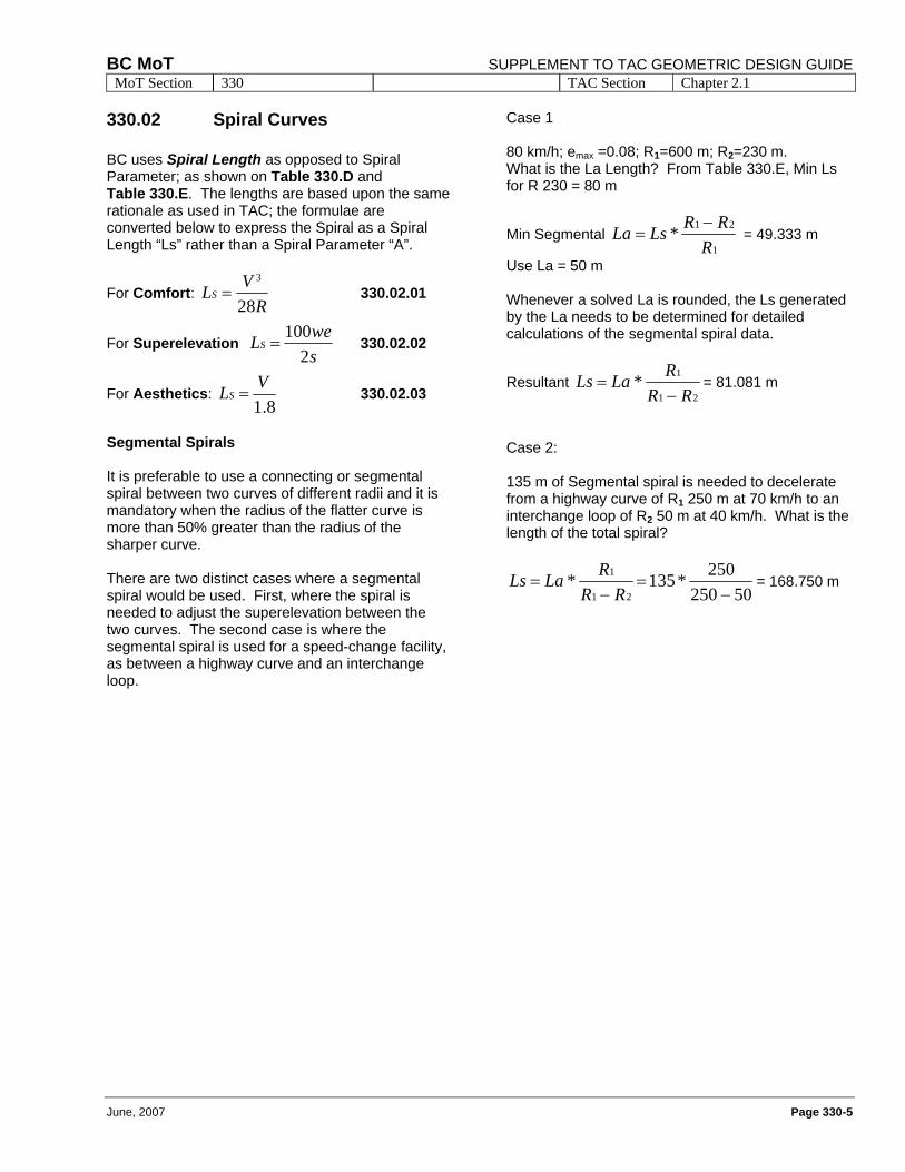
330.02 Spiral Curves BC uses Spiral Length as opposed to Spiral Parameter; as shown on Table 330.D and Table 330.E. The lengths are based upon the same rationale as used in TAC; the formulae are converted below to express the Spiral as a Spiral Length “Ls” rather than a Spiral Parameter “A”.
For Comfort: R
VLS28
3
= 330.02.01
For Superelevation sweLS
2100
= 330.02.02
For Aesthetics: 8.1
VLS = 330.02.03
Segmental Spirals It is preferable to use a connecting or segmental spiral between two curves of different radii and it is mandatory when the radius of the flatter curve is more than 50% greater than the radius of the sharper curve. There are two distinct cases where a segmental spiral would be used. First, where the spiral is needed to adjust the superelevation between the two curves. The second case is where the segmental spiral is used for a speed-change facility, as between a highway curve and an interchange loop.
Case 1 80 km/h; emax =0.08; R1=600 m; R2=230 m. What is the La Length? From Table 330.E, Min Ls for R 230 = 80 m
Min Segmental 1
21*R
RRLsLa −= = 49.333 m
Use La = 50 m Whenever a solved La is rounded, the Ls generated by the La needs to be determined for detailed calculations of the segmental spiral data.
Resultant 21
1*RR
RLaLs−
= = 81.081 m
Case 2: 135 m of Segmental spiral is needed to decelerate from a highway curve of R1 250 m at 70 km/h to an interchange loop of R2 50 m at 40 km/h. What is the length of the total spiral?
50250250*135 *
21
1
−=
−=
RRRLaLs = 168.750 m
SUPPLEMENT TO TAC GEOMETRIC DESIGN GUIDE BC MoT MoT Section 330 TAC Section Chapter 2.1
Page 330-6 June, 2007
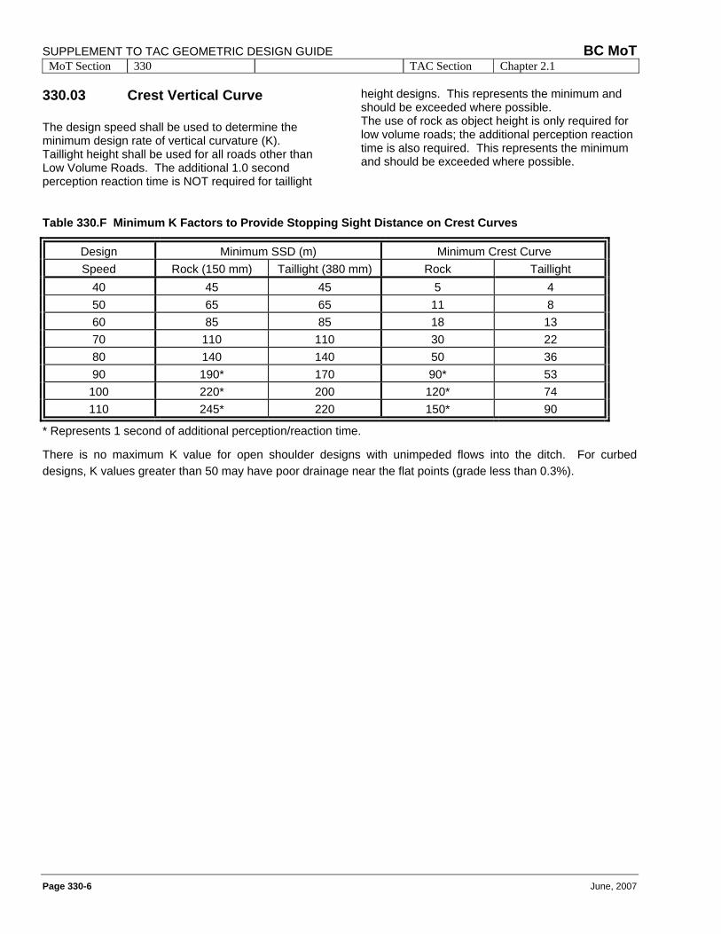
330.03 Crest Vertical Curve The design speed shall be used to determine the minimum design rate of vertical curvature (K). Taillight height shall be used for all roads other than Low Volume Roads. The additional 1.0 second perception reaction time is NOT required for taillight
height designs. This represents the minimum and should be exceeded where possible. The use of rock as object height is only required for low volume roads; the additional perception reaction time is also required. This represents the minimum and should be exceeded where possible.
Table 330.F Minimum K Factors to Provide Stopping Sight Distance on Crest Curves
Design Minimum SSD (m) Minimum Crest Curve Speed Rock (150 mm) Taillight (380 mm) Rock Taillight
40 45 45 5 4 50 65 65 11 8 60 85 85 18 13 70 110 110 30 22 80 140 140 50 36 90 190* 170 90* 53
100 220* 200 120* 74 110 245* 220 150* 90
* Represents 1 second of additional perception/reaction time.
There is no maximum K value for open shoulder designs with unimpeded flows into the ditch. For curbed designs, K values greater than 50 may have poor drainage near the flat points (grade less than 0.3%).
BC MoT SUPPLEMENT TO TAC GEOMETRIC DESIGN GUIDE MoT Section 330 TAC Section Chapter 2.1
June, 2007 Page 330-7
330.04 Vertical and Horizontal
Alignments Near and On Bridges
Alignment Constraints
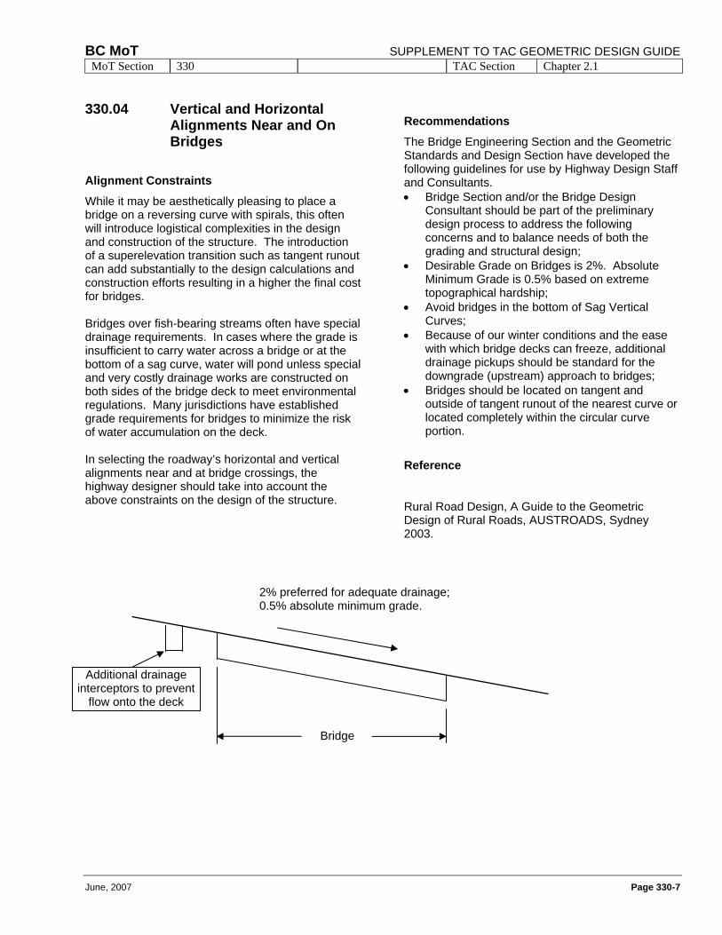
While it may be aesthetically pleasing to place a bridge on a reversing curve with spirals, this often will introduce logistical complexities in the design and construction of the structure. The introduction of a superelevation transition such as tangent runout can add substantially to the design calculations and construction efforts resulting in a higher the final cost for bridges. Bridges over fish-bearing streams often have special drainage requirements. In cases where the grade is insufficient to carry water across a bridge or at the bottom of a sag curve, water will pond unless special and very costly drainage works are constructed on both sides of the bridge deck to meet environmental regulations. Many jurisdictions have established grade requirements for bridges to minimize the risk of water accumulation on the deck. In selecting the roadway’s horizontal and vertical alignments near and at bridge crossings, the highway designer should take into account the above constraints on the design of the structure.
Recommendations
The Bridge Engineering Section and the Geometric Standards and Design Section have developed the following guidelines for use by Highway Design Staff and Consultants. • Bridge Section and/or the Bridge Design
Consultant should be part of the preliminary design process to address the following concerns and to balance needs of both the grading and structural design;
• Desirable Grade on Bridges is 2%. Absolute Minimum Grade is 0.5% based on extreme topographical hardship;
• Avoid bridges in the bottom of Sag Vertical Curves;
• Because of our winter conditions and the ease with which bridge decks can freeze, additional drainage pickups should be standard for the downgrade (upstream) approach to bridges;
• Bridges should be located on tangent and outside of tangent runout of the nearest curve or located completely within the circular curve portion.
Reference
Rural Road Design, A Guide to the Geometric Design of Rural Roads, AUSTROADS, Sydney 2003.
Additional drainage interceptors to prevent
flow onto the deck
Bridge
2% preferred for adequate drainage; 0.5% absolute minimum grade.

SUPPLEMENT TO TAC GEOMETRIC DESIGN GUIDE BC MoT MoT Section 330 TAC Section Chapter 2.1
Page 330-8 June, 2007
This page is intentionally
left blank
dtyacke
Text Box
dtyacke
Text Box
dtyacke
Text Box
June, 2007

rvoyer
Text Box
rvoyer
Text Box
rvoyer
Text Box
June, 2007
rvoyer
Text Box
rvoyer
Text Box
rvoyer
Text Box
June, 2007
rvoyer
Text Box
rvoyer
Text Box
rvoyer
Text Box
June, 2007

rvoyer
Text Box
rvoyer
Text Box
rvoyer
Text Box
June, 2007

SUPPLEMENT TO TAC GEOMETRIC DESIGN GUIDE BC MoT MoT Section 340 TAC Section Not Applicable
Page 340-8 June, 2007
This page is intentionally left blank