30 Series PRESSURE CALIBRATOR - JM Test Systems · Every 30 Series Calibrator is fully temperature...
16
C R Y S T A L engineering corporation 30 Series PRESSURE CALIBRATOR Operation Manual
Transcript of 30 Series PRESSURE CALIBRATOR - JM Test Systems · Every 30 Series Calibrator is fully temperature...
C R Y S T A L engineering corporation
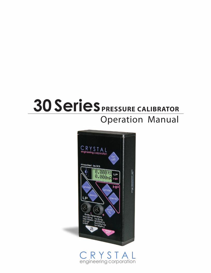
30 Series PRESSURE CALIBRATOR
Operation Manual

ContentsIntroduction . . . . . . . . . . . . . . . . . . . . . . . . . . . . . . . . . . . . . . . . . . . . . . . . . . . . . . . .1Operating Instructions . . . . . . . . . . . . . . . . . . . . . . . . . . . . . . . . . . . . . . . . . . . . . . . .2
Zero . . . . . . . . . . . . . . . . . . . . . . . . . . . . . . . . . . . . . . . . . . . . . . . . . . . . . . . . . . . . . . . . . . . 2Over-range Indication . . . . . . . . . . . . . . . . . . . . . . . . . . . . . . . . . . . . . . . . . . . . . . . . . . . 2Contrast button . . . . . . . . . . . . . . . . . . . . . . . . . . . . . . . . . . . . . . . . . . . . . . . . . . . . . . . . . 2Units button and mA / % button . . . . . . . . . . . . . . . . . . . . . . . . . . . . . . . . . . . . . . . . . . . . 3On/Off button . . . . . . . . . . . . . . . . . . . . . . . . . . . . . . . . . . . . . . . . . . . . . . . . . . . . . . . . . . . 3Changing the battery . . . . . . . . . . . . . . . . . . . . . . . . . . . . . . . . . . . . . . . . . . . . . . . . . . . . 3Reset . . . . . . . . . . . . . . . . . . . . . . . . . . . . . . . . . . . . . . . . . . . . . . . . . . . . . . . . . . . . . . . . . . 3Measuring Vacuum . . . . . . . . . . . . . . . . . . . . . . . . . . . . . . . . . . . . . . . . . . . . . . . . . . . . . . 4Calibration . . . . . . . . . . . . . . . . . . . . . . . . . . . . . . . . . . . . . . . . . . . . . . . . . . . . . . . . . . . . . 4
30 Series Model Numbering System . . . . . . . . . . . . . . . . . . . . . . . . . . . . . . . . . . . .4Serial Numbering System . . . . . . . . . . . . . . . . . . . . . . . . . . . . . . . . . . . . . . . . . . . . .5Specifications . . . . . . . . . . . . . . . . . . . . . . . . . . . . . . . . . . . . . . . . . . . . . . . . . . . . . . .5
Pressure . . . . . . . . . . . . . . . . . . . . . . . . . . . . . . . . . . . . . . . . . . . . . . . . . . . . . . . . . . . . . . . .5Vacuum . . . . . . . . . . . . . . . . . . . . . . . . . . . . . . . . . . . . . . . . . . . . . . . . . . . . . . . . . . . . . . . 5Temperature . . . . . . . . . . . . . . . . . . . . . . . . . . . . . . . . . . . . . . . . . . . . . . . . . . . . . . . . . . . . 5Humidity . . . . . . . . . . . . . . . . . . . . . . . . . . . . . . . . . . . . . . . . . . . . . . . . . . . . . . . . . . . . . . . 5SI (metric) Versions . . . . . . . . . . . . . . . . . . . . . . . . . . . . . . . . . . . . . . . . . . . . . . . . . . . . . . 6Media Compatibility (LP and HP) . . . . . . . . . . . . . . . . . . . . . . . . . . . . . . . . . . . . . . . . . . . 6Pressure Conversions . . . . . . . . . . . . . . . . . . . . . . . . . . . . . . . . . . . . . . . . . . . . . . . . . . . . 6Electrical . . . . . . . . . . . . . . . . . . . . . . . . . . . . . . . . . . . . . . . . . . . . . . . . . . . . . . . . . . . . . . . 6Power . . . . . . . . . . . . . . . . . . . . . . . . . . . . . . . . . . . . . . . . . . . . . . . . . . . . . . . . . . . . . . . . . 7Connections . . . . . . . . . . . . . . . . . . . . . . . . . . . . . . . . . . . . . . . . . . . . . . . . . . . . . . . . . . . . 7
Accessories . . . . . . . . . . . . . . . . . . . . . . . . . . . . . . . . . . . . . . . . . . . . . . . . . . . . . . . .7Fitting Kits . . . . . . . . . . . . . . . . . . . . . . . . . . . . . . . . . . . . . . . . . . . . . . . . . . . . . . . . . . . . . . 8Test Leads . . . . . . . . . . . . . . . . . . . . . . . . . . . . . . . . . . . . . . . . . . . . . . . . . . . . . . . . . . . . . . 8Handpumps . . . . . . . . . . . . . . . . . . . . . . . . . . . . . . . . . . . . . . . . . . . . . . . . . . . . . . . . . . . . 8Software . . . . . . . . . . . . . . . . . . . . . . . . . . . . . . . . . . . . . . . . . . . . . . . . . . . . . . . . . . . . . . . 9
Units, Resolution and Maximum Pressure Ratings . . . . . . . . . . . . . . . . . . . . . . . . .9Enclosure . . . . . . . . . . . . . . . . . . . . . . . . . . . . . . . . . . . . . . . . . . . . . . . . . . . . . . . . .10Intrinsically Safe Certifications . . . . . . . . . . . . . . . . . . . . . . . . . . . . . . . . . . . . . . . .11
CSA . . . . . . . . . . . . . . . . . . . . . . . . . . . . . . . . . . . . . . . . . . . . . . . . . . . . . . . . . . . . . . . . . . 11LCIE\CENELEC . . . . . . . . . . . . . . . . . . . . . . . . . . . . . . . . . . . . . . . . . . . . . . . . . . . . . . . . . 11
Certifications . . . . . . . . . . . . . . . . . . . . . . . . . . . . . . . . . . . . . . . . . . . . . . . . . . . . . .11C-tick . . . . . . . . . . . . . . . . . . . . . . . . . . . . . . . . . . . . . . . . . . . . . . . . . . . . . . . . . . . . . . . . 11
European Community Declaration of Conformity . . . . . . . . . . . . . . . . . . . . . . . .12How to Contact Us: . . . . . . . . . . . . . . . . . . . . . . . . . . . . . . . . . . . . . . . . . . . . . . . . .13Warranty . . . . . . . . . . . . . . . . . . . . . . . . . . . . . . . . . . . . . . . . . . . . . . . . . . . . . . . . . .13

30 Series Operation Manual • Page �
C R Y S T A L engineering corporation
Introduction
Thank you for choosing a Pressure Calibrator from Crystal Engineering Corporation.
The 30 Series are compact and rugged pressure calibrators designed to bring laboratory accuracy to outdoor field conditions. Every 30 Series Calibrator is fully temperature compensated through extensive testing of all measured parameters while being exposed to environments of 0°C (32°F) to 50°C (122°F).
All 30 Series calibrators are intended for gauge pressure measurement. That is, they indicate the difference between applied pressure and ambient barometric pressure. The zero button also can be used as a tare function - extending the functionality of the calibrator for special applications.
Although they weigh less than a pound, advanced technology is employed throughout the prod-uct line. Sensors are constructed with stainless steel isolation diaphragms and permanent oil fill. This means 30 Series products can be used with gases and liquids.
Long battery life is achieved with a low power, RISC (reduced instruction set) type micro-control-ler for computation of complex algorithms. A 24 bit analog to digital converter provides internal resolution of 1 part in 16.7 million. Internal resolution always exceeds the displayed resolutions for all measurements. Full accuracy is maintained even while the low battery icon is flashing.
The 30 Series is specified in percent of reading instead of percent of scale. Why? Because one calibrator could replace a series of calibrators by covering a wide range of pressure with high ac-curacy.
There are no internal potentiometers: All adjustments are accomplished via the optically isolated RS-232 interface. Power for the RS-232 communication is provided by the host PC. Therefore, there are no exposed “live” pins when not connected to a PC.
Your 30 Series can be customized through the use of ConfigM30™ software available from Crystal Engineering. Your personal computer can disable, enable or modify a variety of features of your 30 Series. Look for the ConFIGM30PROGRAMMABLE logo for programmable features, like:
• add or create new pressure units and/or disable unused pressure units
• password protection to prevent unauthorized changes
• load and save custom configurations
• view and print an as received versus as left change report
• select your preferred H2O water density: 4°C, 60°F, or 68°F/20°C
• store a message or identification number
• adjust (calibrate) the gauge
Finally, the 30 Series is manufactured and serviced by a company that only makes pressure mea-suring equipment. It’s the only thing we do and that’s why we say: PRESSURE is Our BUSINESS™

Page � • 30 Series Operation Manual
C R Y S T A L engineering corporation
Operating Instructions
To ensure safe and accurate operation, please be familiar with the following warnings:
WARNINGS
Severe injury or damage can occur through improper use of pressure instruments! Do not ex-ceed recommended pressure limits of tubing and fittings. Be certain all pressure connections are secured.
This gauge can display zero pressure when connected to a source of pressure! Do not rely on the display indication before disconnecting - it may not be indicating true pressure. Never discon-nect pressure instrumentation without first relieving system pressure!
CAUTION: Never insert any object (other than the ⅛” NPT fitting) into the pressure connection! The sensor diaphragm is very thin and can be damaged or destroyed by solid or sharp objects. Cleaning of the sensor must be done with appropriate solvents only.
ZeroTo make sure that the calibrator is performing to its rated accuracy, it should be exercised and re-zeroed whenever exposed to changes in temperature (see Specifications). It’s also good practice to check zero as your final reading too, as these calibrators should return to a perfect zero reading. The 30 series does not automatically re-zero when first turned on. The zero button can be used as a “tare” button because it will “zero out” any value the selected range is capable of displaying. The zero reading may also shift when the calibrator is moved from a vertical to a horizontal orientation. This is due to the oil filling that transmits the pressure signal from the stainless steel diaphragm to the silicon pressure sensor. The magnitude of the shift is typically 0.3”H2O or less.
Over-range IndicationOver-range conditions will be indicated regardless of the tare value. If the low or high pressure full scale ratings are exceeded by 10% or more, appropriate warning messages will be displayed. Also, if the milliamp input exceeds 55 mA a warning message will appear.
Model 33, only: These messages will only appear if the parameter being measured is selected for display. For example, if the milliamp input is greater than 55 mA, but milliamps is not selected for display, no over-range warning will be indicated. (The milliamp input is protected by a semicon-ductor type fuse that automatically resets once the fault condition is removed.)
Contrast button The contrast button, left of the display, may never have to be pressed. It is provided to compen-sate for slight contrast changes with temperature and component aging. Press the button and the

30 Series Operation Manual • Page 3
C R Y S T A L engineering corporation
contrast will increase. If you press the contrast button repeatedly enough times the display will jump to the least contrast setting, allowing you to adjust it darker until you get the best contrast and legibility.
Units button and mA / % buttonPressing the units button updates the display to the next unit selection. The mA button scrolls through direct milliamps, % 4-20 and %10-50.
Model 33s (only) will display the following combinations of pressure and/or milliamps:
Top Line
Bottom Line
If LP, HP or mA are not being displayed, press the respective button and the parameter will appear. If the parameter is already on screen, pressing the corresponding button will cause it to cycle to the next scale or units for that button.
On/Off buttonThis function is obvious. What is not obvious is that all the settings are saved when you turn the unit off. When you turn the unit back on it will be set to the same combinations of ranges and scales. Even the zero or tare value stays the same.
Changing the batteryThe battery is located on top of the unit, under the sliding cover. Batteries must only be changed in a non-hazardous area! The best way to change the battery is to first turn off the unit, then replace the battery. All settings will be retained if battery replacement is done this way. If the unit is stored for a long time, the battery should be removed, to avoid potential damage from bat-tery leakage. If the battery has been removed for storage or the battery was disconnected while the unit was on, the unit will automatically reset 5 to 10 seconds after reconnecting the battery.
WARNING
The 30 Series is approved as intrinsically safe only if powered by one of the following battery types: Duracell® Alkaline 9V, MN 1604 or Eveready® 9V, P/N 216.
ResetIf for some reason the unit needs to be reset, remove the battery. Either wait one minute, or short circuit the battery snap connections with any metal object. If the reset is successful the unit will begin operating when the battery is reconnected without pressing the “ON” button.

Page � • 30 Series Operation Manual
C R Y S T A L engineering corporation
Measuring VacuumAll sensors in 30 series calibrators can be used to measure vacuum, but only ranges rated at 300 PSI (2000 kPa) or less have actually been certified. (Refer to your calibration certificate.) When measuring pressure less than ambient conditions the display will show a minus (-) sign in the left most position. On some scales (like kilograms per square centimeter which has 4 decimal places of resolution), this will cause the display to shift right one digit. Resolution won’t be lost, but part of the range icon will disappear until positive pressure is restored.
CAUTION: 30 Series calibrators are not recommended for continuous use at high vacuum.
CalibrationThere are no potentiometers. The 30 Series contains a “span” factor (Userspan) set to approximate-ly 1 at the factory. As components age, this may need to be changed to a slightly higher or lower value to slightly increase or decrease readings. If adjustment is required, we recommend return-ing the unit to the factory, though this adjustment can be made with a computer running ConfigM30 software. Refer to the Software descriptions later in this book. Zero the calibrator, then record the displayed pressure for two or more pressure points to determine if the 30 Series would benefit from an overall increase or decrease of the indicated pressure.
Factory service offers benefits you won’t find anywhere else. We have the facilities to provide calibration reports that include test data at a variety of temperatures utilizing NIST traceable stan-dards. In addition, upgrades may be available to add or enhance operating features. We designed the product to last, and we support it so that you can get the most from your investment.
30 Series Model Numbering System
This manual applies to all models in the current 30 Series product line. To determine the specifications for your model, use this table to decode the model number.Model SI- IS 33 - 200/2000 KPA - SPSS
SI: Metric pressure units only
1 = Single pressure sensor3 = Dual pressure sensors
Manifold Type: Omit = Standard SPSS = Stainless Steel
Approved Intrinsically Safe by agencies listed in this brochure.
PSI or KPA(on models with SI pre�x only)
First pressure range: in PSI or kPa
Second pressure range: in PSI, or kPa (Model 33 only)
30 Series Operation Manual • Page �
C R Y S T A L engineering corporation
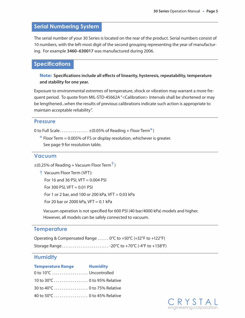
Serial Numbering System
The serial number of your 30 Series is located on the rear of the product. Serial numbers consist of 10 numbers, with the left-most digit of the second grouping representing the year of manufactur-ing. For example 3�60–6300�7 was manufactured during 2006.
Specifications
Note: Specifications include all effects of linearity, hysteresis, repeatability, temperature and stability for one year.
Exposure to environmental extremes of temperature, shock or vibration may warrant a more fre-quent period. To quote from MIL-STD-45662A “<Calibration> Intervals shall be shortened or may be lengthened...when the results of previous calibrations indicate such action is appropriate to maintain acceptable reliability”.
Pressure0 to Full Scale . . . . . . . . . . . . . . . ±(0.05% of Reading + Floor Term* )
* Floor Term = 0.005% of FS or display resolution, whichever is greater. See page 9 for resolution table.
Vacuum±(0.25% of Reading + Vacuum Floor Term† )
† Vacuum Floor Term (VFT):
For 16 and 36 PSI, VFT = 0.004 PSI
For 300 PSI, VFT = 0.01 PSI
For 1 or 2 bar, and 100 or 200 kPa, VFT = 0.03 kPa
For 20 bar or 2000 kPa, VFT = 0.1 kPa
Vacuum operation is not specified for 600 PSI (40 bar/4000 kPa) models and higher. However, all models can be safely connected to vacuum.
TemperatureOperating & Compensated Range . . . . . . 0°C to +50°C (+32°F to +122°F)
Storage Range . . . . . . . . . . . . . . . . . . . . . . . . . -20°C to +70°C (-4°F to +158°F)
HumidityTemperature Range Humidity0 to 10°C . . . . . . . . . . . . . . . . . . . Uncontrolled
10 to 30°C . . . . . . . . . . . . . . . . . . 0 to 95% Relative
30 to 40°C . . . . . . . . . . . . . . . . . . 0 to 75% Relative
40 to 50°C . . . . . . . . . . . . . . . . . . 0 to 45% Relative
Page 6 • 30 Series Operation Manual
C R Y S T A L engineering corporation
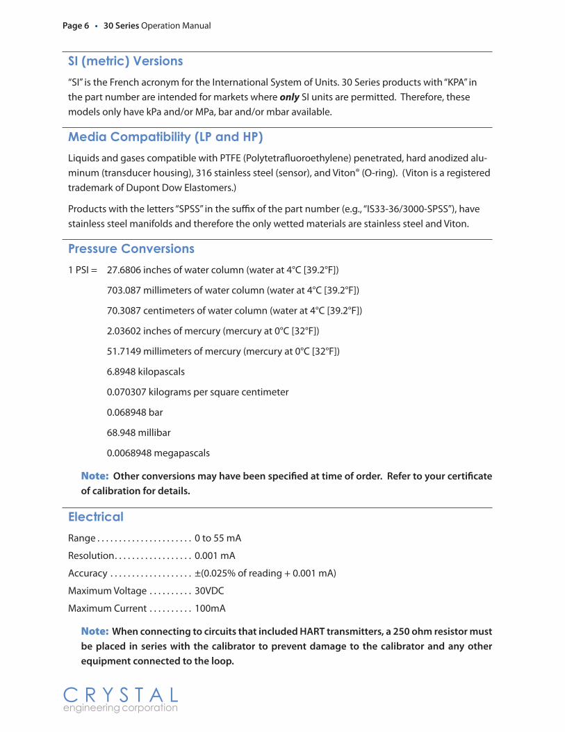
SI (metric) Versions“SI” is the French acronym for the International System of Units. 30 Series products with “KPA” in the part number are intended for markets where only SI units are permitted. Therefore, these models only have kPa and/or MPa, bar and/or mbar available.
Media Compatibility (LP and HP)Liquids and gases compatible with PTFE (Polytetrafluoroethylene) penetrated, hard anodized alu-minum (transducer housing), 316 stainless steel (sensor), and Viton® (O-ring). (Viton is a registered trademark of Dupont Dow Elastomers.)
Products with the letters “SPSS” in the suffix of the part number (e.g., “IS33-36/3000-SPSS”), have stainless steel manifolds and therefore the only wetted materials are stainless steel and Viton.
Pressure Conversions1 PSI = 27.6806 inches of water column (water at 4°C [39.2°F])
703.087 millimeters of water column (water at 4°C [39.2°F])
70.3087 centimeters of water column (water at 4°C [39.2°F])
2.03602 inches of mercury (mercury at 0°C [32°F])
51.7149 millimeters of mercury (mercury at 0°C [32°F])
6.8948 kilopascals
0.070307 kilograms per square centimeter
0.068948 bar
68.948 millibar
0.0068948 megapascals
Note: Other conversions may have been specified at time of order. Refer to your certificate of calibration for details.
ElectricalRange . . . . . . . . . . . . . . . . . . . . . . 0 to 55 mA
Resolution . . . . . . . . . . . . . . . . . . 0.001 mA
Accuracy . . . . . . . . . . . . . . . . . . . ±(0.025% of reading + 0.001 mA)
Maximum Voltage . . . . . . . . . . 30VDC
Maximum Current . . . . . . . . . . 100mA
Note: When connecting to circuits that included HART transmitters, a ��0 ohm resistor must be placed in series with the calibrator to prevent damage to the calibrator and any other equipment connected to the loop.

30 Series Operation Manual • Page 7
C R Y S T A L engineering corporation
PowerBattery . . . . . . . . . . . . . . . . . . . . . One Alkaline or Lithium 9V battery
Approved Batteries . . . . . . . . . The 30 series is approved as intrinsically safe only if powered by one of the following battery types:
Duracell® Alkaline 9V, MN 1604 Eveready® 9V, P/N 216
Battery Life . . . . . . . . . . . . . . . . . 90 hours typical
Low Battery Indicator . . . . . . . Flashing battery icon
Many other battery types and models have been tested but failed to meet the requirements for potentially explosive atmospheres—do not assume other models are equivalent.
ConnectionsPressure Fitting . . . . . . . . . . . . . ⅛” female NPT
Milliamperes . . . . . . . . . . . . . . . 4mm jacks, 19mm (0.75") spacing
Accessories
We offer a full range of accessories, including hand pumps, fitting kits, pressure hoses, silicone test lead sets and the most complete and compact waterproof carrying cases available. The carry-ing cases (with custom diecut foam inserts) can be ordered complete with all the accessories you
need to maximize your productivity on the job. Refer to the Crystal Handpumps and Accessories brochure for more information on our complete line of easy to use quick-connect fittings and fitting kits, handpumps, and other accessories. You can also contact your local distributor, or any of the contact numbers or addresses at the back of this manual, for more information.

Page � • 30 Series Operation Manual
C R Y S T A L engineering corporation
Fitting KitsCrystal supplies a full range of fittings (available individually or grouped into kits) for use with both the 30 Series calibrator and our portable handpumps. For a complete list of fittings and fitting kits available, refer to the Crystal Handpumps and Accessories brochure. You may also contact your local distributor, or use one of the numbers listed on the inside back page to speak directly to Crystal’s knowledgeable, helpful sales staff.
Test LeadsOur test lead kit features high quality banana to banana test leads with rugged, hard plastic insulated alligator clips. Test Lead Kit P/N: 1351
HandpumpsCrystal offers three different handpump options. All provide a portable pressure source for the calibration of 30 Series calibra-tors, as well as other high pressure gauges, recorders, switches and transmitters. A built-in variable volume control makes it easy to set precise pressure with the turn of a dial. Additionally, the CylinderPump and ComboPump can serve as both a pressure and vacuum source. CylinderPump P/N: 80 PSI–�936 HydraulicPump P/Ns: 3000 PSI–���9; 5000 PSI–���0 ComboPump P/Ns: 300PSI–�907; 500 PSI–�90�

30 Series Operation Manual • Page 9
C R Y S T A L engineering corporation
Units, Resolution and Maximum Pressure Ratings
Your unit will have one or two of these pressure ranges and corresponding display resolution:
Pressure Range Available Pressure Units and Resolution
Range PSI
Range bar
Range kPa*
Over- pressure PS
I
kg/cm
2
inch
Hg
inch
H2O
mm
Hg
cmH 2O
mm
H 2O
kPa
MPa
mba
r
bar
16 1 100 6.5 x 0.001 0.0001 0.001 0.01 0.01 1 0.01 0.136 2 200 3.0 x 0.001 0.0001 0.001 0.01 0.01 1 0.01 0.1
300 20 2000 2.0 x 0.01 0.001 0.01 0.1 0.1 1 0.1 0.001600 40 4000 2.0 x 0.01 0.001 0.1 0.0001 0.001
1500 100 10000 2.0 x 0.1 0.01 1 0.001 0.01
3000 200 20000 1.5 x 0.1 0.01 1 0.001 0.01
*kPa versions are restricted to kPa, MPa, bar or millibar, depending on pressure range. PSI versions include all possible scales except bar for 36 PSI ranges and lower and mbar for the 300 PSI version.
Bar versions include all possible scales except inch Hg for the 2 bar ranges and lower.
SoftwareConfigM30: Customize your calibrator! Eliminate scales you don’t need, calibrate the gauge, create custom scales and password protect the calibrator from future changes! Available from our website at www.crystalengineering.net. (Requires RS232 cable, PN 1928).
LabVIEW™ Drivers: The Model 30 LabVIEW Driver Library is a set of VIs that implement the serial commands of the Model 30. The library also provides parsing of the streaming data output, placing it into a simple cluster for easy access.
SerialDL: SerialDL is a free command line program that will log data from any 30 Series pressure calibrator, create a comma delimited text file, and can automatically format the data into a Micro-soft® Excel spreadsheet.

Page �0 • 30 Series Operation Manual
C R Y S T A L engineering corporation
Enclosure
Description . . . . . . . . . . . . . . . . . Extruded Aluminum with sealed membrane keypad.
Weight: . . . . . . . . . . . . . . . . . . . . . Model 33 - 400.3g (14.1 oz.); Model 31 - 342g (12.1 oz.); Model 31, High Pressure - 360g (12.7 oz.)
Weight w/SS Manifold: . . . . . . Model 33 - 484.6g (17.0 oz); Model 31 - 428g (15.1 oz.); Model 31, High Pressure - 360g (12.7 oz.)
Carry Case w/strap: . . . . . . . . . PN 2490 (included). Clear cover protects keypad - calibrator can be . . . . . . . . . . . . . . . . . . . . . . . . . . . . operated while in case. Also provides a way to hang the calibrator . . . . . . . . . . . . . . . . . . . . . . . . . . . . while in use.
C R Y S T A L engineering cor po ra tion
model is33
on
units units
36 psi
3000 psi
zero zero
HP
LP
off
mA %
LP
HP
2 LINE X 8 CHARACTER LCD DISPLAY
69.8 (2.75)
137.2(5.40)
29.2 (1.15)
ALL DIMENSIONS ARE IN MILLIMETERS (INCHES)
SENSOR DIAPHRAGMLOCATIONS
LP distance to diaphragm (-A- to -B-): 22.4 (0.88”)LP volume: 2 milliliters (0.13 cubic inches)HP distance to diaphragm (-A- to -B-): 17.8 (0.70”)HP volume: 1 milliliter (0.06 cubic inches)
PRESSURE PORTVOLUMETRIC DATA:
1/8” FNPTPRESSURE PORTS
- B -
ø4mmSHIELDED
BANANA JACKS
- A -

30 Series Operation Manual • Page ��
C R Y S T A L engineering corporation
Intrinsically Safe Certifications
Crystal Engineering pressure calibrators starting with “IS” in the part number have been certified intrinsically safe by the following agencies per the listed standards:
CSAIntrinsically Safe, Entity Parameters - for Hazardous Locations: Class I, Groups A, B, C and D; Temperature Code T4
LCIE\CENELECEEx ia IIC, T4
Milliamp Input Entity Parameters:
Vmax=30V=Ui Voc=5V=Uo
Imax=100mA=li Isc=400mA=lo
Ci=2.3µF Ca=0.135µF=Co
Li=0mH La=100µH=Lo
Entity parameters specify the safe voltage, current, capacitance and inductance that can either be connected to the device, or is internal to the device.
WARNINGS
Substitution of battery components may impair intrinsic safety. Use only:Duracell® Alkaline 9V, MN �60�Eveready® 9V, P/N ��6
Do not use the RS232 connector in a potentially explosive atmosphere.
Replace batteries in non-hazardous locations with approved types only.
Certifications
The 30 Series calibrator has been tested and certified to comply with a variety of international standards.
C-tickThis 30 Series calibrator complies with the Australian requirements for the C-tick mark. The instrument was tested against AS/NZS 3584, C-tick EMC/EMI requirements.
LCIE 98.E6046 X

Page �� • 30 Series Operation Manual
C R Y S T A L engineering corporation
European Community Declaration of Conformity
EC Declaration of Conformity
I/We Crystal Engineering Corporation
of 720 Aerovista Place, Suite B San Luis Obispo, CA, 93401 USA
declare that Pressure Calibrator IS31 and IS33
In accordance with the following directives
89/336/EEC The Electromagnetic Compatibility Directive and its amending directives
has been designed and manufactured to the following specifications
EN 50081-1 1992 Electromagnetic compatibility - Generic emission standard -- Part 1: Residential, commercial and light industry
EN 50081-2 1993 Electromagnetic compatibility - Generic emission standard -- Part 2: Industrial environment
IEC 1000-4-2 2001 Ed. 1.2 Electromagnetic compatibility (EMC): Testing and measurement techniques - Electrostatic discharge immunity test
IEC 1000-4-3 2001 Ed. 1.2 Electromagnetic compatibility (EMC)- Testing and measurement techniques - Radiated, radio-frequency, electromagnetic field immunity test
EN 55011 & A1
1998 1999
Industrial, scientific and medical (ISM) radio-frequency equipment - Radio disturbance characteristics - Limits and methods of measurement
I hereby declare that the equipment named above has been designed to comply with the relevant sections of the above referenced specifications. The unit complies with all essential requirements of the Directives
David K. Porter, P.E. (NAME OF AUTHORIZED PERSON)
Director of Engineering (TITLE OF AUTHORIZED PERSON)
16 April 2003 (SIGNATURE OF THE AUTHORIZED PERSON) (DATE OF ISSUE)

30 Series Operation Manual • Page �3
C R Y S T A L engineering corporation
How to Contact Us:
Phone (�0�) �9�-��77
Toll-Free (800) 444-1850
Fax (�0�) �9�-��66
Email [email protected]
Web www.crystalengineering.net
If calling, have ready the model number, serial number, date of purchase and reason for return. You will receive instructions for returning the device to Crystal Engineering.
Send your comments to: [email protected]
Warranty
Crystal Engineering Corporation warrants the 30 Series Pressure Calibrators to be free from
defects in material and workmanship under normal use and service for one (1) year from date
of purchase to the original purchaser. It does not apply to batteries or when the product has
been misused, altered or damaged by accident or abnormal conditions of operation.
Crystal Engineering will, at our option, repair or replace the defective device free of charge
and the device will be returned, transportation prepaid. However, if we determine the failure
was caused by misuse, alteration, accident or abnormal condition of operation, you will be
billed for the repair.
CRYSTAL ENGINEERING CORPORATION MAKES NO WARRANTY OTHER THAN THE LIMITED WAR-
RANTY STATED ABOVE. ALL WARRANTIES, INCLUDING IMPLIED WARRANTIES OF MERCHANT-
ABILITY OR FITNESS FOR ANY PARTICULAR PURPOSE, ARE LIMITED TO A PERIOD OF ONE (1)
YEAR FROM THE DATE OF PURCHASE. CRYSTAL ENGINEERING SHALL NOT BE LIABLE FOR ANY
SPECIAL, INCIDENTAL OR CONSEQUENTIAL DAMAGES, WHETHER IN CONTRACT, TORT OR
OTHERWISE.
Note (USA only): Some states do not allow limitations of implied warranties or the exclusion
of incidental or consequential damages, so the above limitations or exclusions may not apply
to you. This warranty gives you specific legal rights and you may have other rights which vary
from state to state.
PN: 2528—Rev E
C R Y S T A L engineering corporation
© 2007 Crystal Engineering Corporation708 Fiero Lane, Suite 9, San Luis Obispo, California 93401-8701
BUREAU VERITAS
IS0 9001
Certification
No 191559