30-Phone100
41
www.sigmatrainers.com SIGMA TRAINERS AHMEDABAD (INDIA) TELEPHONE TRAINER MODEL-PHONE100 More than 2000 Trainers Since 23 Years TRAINERS
-
Upload
cauvong-justin -
Category
Documents
-
view
145 -
download
6
Transcript of 30-Phone100

www.sigmatrainers.com
SIGMA TRAINERSAHMEDABAD (INDIA)
TELEPHONE TRAINER
MODEL-PHONE100
More than2000
Trainers
Since 23
Years
TRAINERS

2
PRACTICALS
1. Introduction to Telephone System theory 03
2. To Study the Block Diagram and Working principle 12
3. To Study Rectifier protector/Polarity guard section 13
4. To Study Ringer section 14
5. To Study Voltage dropper Section 16
6. To Study Dialer Section 18
7. To Study Keyboard Matrix Section 22
8. To Study Speech Amplifier Section 25
9. To understand and perform operational procedure 29
10. To measure Test Point Voltages for different sections 30
11. To observe Test Point Waveforms for different sections 31
12. To understand different types of faults 33
13. To study Data Sheets of ICs used in telephones 37

3
PRACTICAL-1
INTRODUCTION TO TELEPHONE SYSTEM THEORY
In the year 1876, March 10th, Alexander Graham Bell and his assistant Thomas A. Watson were conducting some electrical experiments. Watson was in his room when he suddenly heard the voice of the Graham Bell calling him "Mr. Watson Come here, want you", on the instrument they were experimenting. This was the first call made using the electricity, i.e. it was the beginning of the telephone system as we know today. From that call in 1876, the telephone system grew very rapidly. The first operational telephone exchange was functional by the year 1818, in the city of New Heaven and by the year 1900, telephone has become a common object in developed countries. Today the telephone has become a multinational, multi crore rupee industry employ- ing millions of people and providing services to the people-in the metro cities as well as in the far off remote villages. Telephone System The word Telephone is made of two different words Tele and Phone, i.e. Distance Communication. Any instrument that allow us to communicate with someone from a distance should be called a telephone. A telephone system should provide a basic facility for two persons, sitting at two different places, to be able to communicate with each other. Today in the telephone system, the component with which the user is most familiar is the telephone set. The telephone set is used to transfer our voice to the called party and it also allow us to hear the response from the called party.
Figure –1 This telephone set is connected to the called party using a telephone line and one or more telephone exchanges. Telephone Set :- The most basic thing that a telephone user comes across in a telephone system is the telephone set. Figure-1 shows two telephone sets connected to each other through a telephone line. Working of a Phone Set: - As you can see in the figure-1, a telephone set is basically made of two parts, a hand- set, which contains a microphone and a speaker as receiver and transmitter respectively, and a main unit, which contains rest of the circuits required to make the telephone work. The main unit also contains a dial pad (rotary. type or key pad type) to dial the number of the required person. Sometimes this dial pad is provided on the handset itself. The handset is connected to the main unit using a coiled cable.

4
When the handset is lifted, the telephone set informs to the phone system that some- one wants to use the system to make a call. The systems readiness to accept and transfer the call is informed to the user by generating a dial tone sound on his phone set. After hearing the dial tone sound on his phone set, the caller informs to the phone system about the person he want to talk to by dialing phone number of the person. For this, the caller rotates number on a rotary switch or pushes the required number on a push button phone. This number being dialed or pushed on the phone set is informed to the phone system by the phone set. Once a number is dialed, the status of the dialed number, whether the bell of the called phone is ringing, or the other phone is busy, etc. is informed by the phone system to the caller through different tones generated at the callers phone set. This could be a ring back tone or a busy tone or some other tone. Once the called party picks up the phone, the speech of the caller is converted into electrical signal by his phone set and it is send through the telephone line. The telephone set converts the speech of the called party, incoming as electrical signal, into audible speech signal. After the talk, when the caller hangs-up or puts the handset back into the cradle, the call is considered finished and the connection with the called party is terminated. When someone dials your number, the phone set indicates about the incoming call be generating an audible tone such as ringing of the bell on the phone set. To communicate with someone, using the telephone set, we need to connect the phone set to a telephone exchange through the telephone lines. A telephone exchange is a place where different phones get interconnected to transfer speech from one phone to another phone, from one person to another person. Local Exchange: - The place where different telephone sets are connected to receive and transfer calls to different phone sets are known as local telephone exchange or a local loop. In the beginning when the number of phone sets were very limited, these phone sets were directly interconnected with each other. But, as the number of phones increased and people wanted to make contact with different phones available in their area, not just the phone they are connected to, this method of directly connecting the phones become impractical and local exchange offices were established at different places to manage the interconnection of the telephone sets. In a local exchange system, each telephone set is connected to the exchange office. The exchange contains switching equipment, signaling equipments and batteries to supply DC current to the phone sets. The phone set is connected to the exchange through two conductor wires called wire pair. One of this wire is called Tip and the other is called Ring. This special names comes from the early manual telephone sets, where the plugs were used to make/connect calls and the plug had two parts tip and ring as shown in the figure-2. The switching equipments in the exchange connect one telephone to another. Once the connection is made, the two phone users can communicate over the phone. For this, a DC current supplied by the battery in the exchange carry the sound signal from one place to the other place in the form of varying current.

5
Figure-2
Let us see how this complete process of making connection, talking and ending of the connection take place. Initiating a Call :- Let us see how a call is initiated/started in the phone system. When the handset of the phone is on the cradle, it is called on-hook condition. In this condition the connection between the telephone set and the exchange is open. When the handset is picked up from the cradle, a spring loaded button will close the switch hook and the connection between the exchange and the phone set will become complete. This is called off-hook condition and this condition will start the current flow in the telephone circuit. These terms on-hook and off-hook come from the early telephone days when the receiver and transmitter of a telephone set were separate units and to end a call the receiver was hung on a switch hook. Also, when the phone was not in use, it was kept hung on the hook. The ringer on the phone set is always connected to the exchange. This is the reason one receives the ringing tone even when the phone handset is placed on the cradle. Calling A Number: - Once the handset is picked up, one can press the required number on the keypad, if the phone is of old rotary dial type, then dial the required number by rotating the number. This dialed number can reach the exchange in one of the following formats Pulse Dialing Tone Dialing (DTMF) Pulse Dialing: - Pulse dialing also known as decade dialing is the old method of informing the dialed number to the telephone exchange, currently all the exchange support this dialing method. In this method when a number is dialed on a rotary dial or pressed on a number keypad, based on the dialed number the closed circuit between the local exchange and the telephone set is opened and closed a number of times. This opening and closing or breaking of the connection between the exchange and the telephone set depends on the exchange type being used, but a standard method is when number 1 is pressed, open and close the current loop 1 time,

6
when number 2 is pressed, open and close the loop 2 times, when number 9 is pressed, open and close the loop 9 times, when number 0 is pressed, open and close the loop 10 times. This opening and closing of the connection between the exchange and the phone set is . done at a very high rate. When th1e number 5 is dialed on a pulse based dialing sys- tem, the loop line is broken five times by the dialing circuit. This will inform to the exchange that the caller has dialed number 5. Then after a maximum allowed inter digit interval, the next digit dialed will break the loop line. This method of dialing can be used with any type of exchange, be it older electromechanical exchange or new digital exchange. Tone Dialing: - Tone dialing, also known as DTMF dialing for Dual Tone Multi Frequency or fast dial- ing, is currently the standard method used to pass the dialed telephone number to the exchange. If a phone set is able to dial using the DTMF method, but the exchange can not handle .the DTMF dialing, then one is required to change the phone set to use the pulse dialing method. But, if the exchange can handle the DTMF dialing, then one can dial using either the DTMF dialing or the Pulse dialing method. In the tone dialing system pressing of a key on the keypad generates two different sound tones. The combination of these tones inform to the exchange about the number being pressed. For example, pressing of the number 1 will generate tones 697Hz and 1209Hz, number 5 will generate tones 770Hz and 1336Hz and so on. This generation of double tone, with multiple frequencies gives the name Dual Tone Multi Frequency to this system of dialing.
Figure-3

7
Figure-3 -shows various frequencies generated by a DTMF dialing device when different keys are pressed on the keypad. As shown in this figure, pressing of the number 5 will generate 770Hz, 1366Hz sound sjgnal. When dialing a number using the pulse dialing system and the DTMF dialing system, the DTMF will work much faster than the pulse dialing. That is why this dialing method is also known as Fast Dialing. Making Connection :- Once the exchange gets information about the number you want to be connected to, different combination of switches and relays in the exchange will connect your line to the called numbers line. Once this connection is made, the exchange will transmit different information to the called phone and the position of the called phone will be relayed to your phone. If the called party's phone is off-hook then a called party busy indicator tone is returned to you by the exchange. Otherwise, a ringer signal is sent to the called phone to inform that someone wants to talk and a ring back tone is sent to your phone set to inform that the called party's phone is ringing. To produce the ringing sound in the called phone, a ringer circuit called polarized ringer or Bell developed in 1878 by Thomas A Watson is commonly used. Currently, electronic ringing circuits are replacing this Bell circuit from the new telephone sets. Answering a Call :- When the called party picks up the phone handset, after hearing the ringing tone, the switch hook of his phone will close and the current loop from your phone to his phone will get completed. Now the loop current will flow from the caller 's phone to the called phone. Once the loop is completed, the exchange will remove the ringer signal and the ring back tone from the line. Conversation :- Once the called party picks up the phone and the loop current starts to flow from the caller 's phone to the called phone, the conversation can be started. That part of the handset into which one speaks is known as transmitter. This transmitter converts the sound signal into varying electrical signal. This is done by changing the loop current in accordance with the speech of the talker. Other part of the handset which is used to hear the other person is called receiver. The. receiver converts the incoming varying electrical signals into sound signal so that one can hear what the person on the other side of the line is saying. The signal produced at one end by the transmitter, is taken to the receiver at the other end by the variations in the loop current. A small part of the transmitted signal is also fed back into the talker's receiver. This signal is known as side tone signal and is used to provide a feedback to the person using a telephone set about how loudly he/she should speak. The side tone signal allows the caller to hear his/her own voice during conversation. This allows him/her to adjust the loudness of the voice to provide proper loudness: at the called phone.

8
Ending a Call :- Once the conversation is over, the call can be ended by placing the handset back onto the cradle. Some exchanges allow the call to be ended by either person, the caller or the called party, whereas some exchange allow the call to be ended only by the caller by putting. the telephone handset back into the cradle, in on-hook position. Hook Switch:- The hook switch is a set of switches that close when the receiver or the handset is lifted from the cradle of the telephone unit. When the handset is replaced back to the cradle, the switch opens. The closed position of the hook is known as on-hook position and the open position is known as off-hook position.
Figure-4 On-Hook :- In the on-hook position as shown in the figure-4, the ringer circuit is connected across the incoming line. This makes it to be able to generate the ringer tone even when the handset is placed on the hook switch. No DC current flows through the ringer circuit because of the capacitor used to block the DC current. In this on-hook position, remaining circuits, other than the ringer circuit, is isolated from the line because of the open contacts of the switch hooks. Off-Hook :- When the telephone handset is lifted from the cradle of the telephone set, the switch hook 81 and 82 will close and a loop current from the battery in the exchange to the phone system starts flowing. This flow of the current through the circuits of the telephone makes the relay coil in the phone to get energized. Once the relay gets energized and closes, this signals to the local exchange that a subscriber's telephone set is in off-hook position. This information makes a line finder in the exchange to look for a line with off-hook signal. Next, the line finder sets up the connections for the switching equipment to begin receiving the telephone number being dialed by the user. Once these operations are finished a dial-tone generator is connected to the phone line to inform to the caller to start the dialing process. Transmitter: - After looking at the dialing part of the telephone instrument, let us look at another important component of the telephone system, namely transmitter.

9
That part of the telephone instrument into which a person talks is called the transmitter. The job of a transmitter in a telephone set is to convert the sound signal into variations of electrical signal that can be transmitted over the phone line.
Figure-5 There are many different types of transmitter in use but the most common transmitter using the carbon granule is based on the principle invented by Thomas A. Edison around 100 years ago. This transmitter is shown in fiSgure-5. Two more common transmitters are electromagnetic or electrodynamics microphone and electrets microphone. Receiver :- After the transmitter, the next important part of a telephone set is the receiver. The receiver recreates the sound of the person who is on the other end of the line. This sound comes in the form of varying electrical signal, which is converted into sound signal by the receiver. For this, a common method is to use a transducer. A transducer produces sound by making use of changing magnetic field induced on a coil, in the magnetic field of a permanent magnet, by the effect of the variations in the incoming current. The resultant attraction and repulsion between permanent magnetic field and the induced magnetic field will vibrate a diaphragm producing the sound signal. A typical electromagnetic receiver is shown in the figure-B. As shown in this figure this receiver consists of a coils of wire wound on a permanently magnetized soft iron that drive an armature. This armature is a diaphragm made of a soft iron material.
Figure-6

10
A permanent magnet is also there to provide a constant bias field for the varying electromagnetic field to work against. The changing electrical current . representing speech at the other end of the phone line flows through the coils and produces a varying electromagnetic field. This field will attract or push the permanent magnet field alternately increasing and decreasing the total magnetic field acting on the diaphragm. This will causes the diaphragm to vibrate and moves the air to reproduce the original speech that produced the varying current at the first place. This same technique is used in a loudspeakers to generate sound. Ringer :- Ringer is another important part of the telephone set. Initially when the telephone was introduced, it had no ringing facility. Instead people used to shout in the phone to get other persons attention. But later the ringing circuit was added to the telephone circuit.
Figure-7 This ringing circuit produced loud enough sound by using different methods to get immediate attention of the telephone users. When a calls made, the exchange sends a signal to the called party to inform that there is an incoming call. This will make the ringer in his phone to operate and produce the sound to attract his attention. The ringer sound is chosen such that it is loud enough to be heard from a distance place and this should also sound urgent so that the person on the other end will pick up the phone. The traditional metallic gong bell which is struck by a metal clapper is the most common type of the ringer used with the traditional type of the phone instruments. This design of bell, shown in the figure- 7, was patented in the year 1878 by Mr. Thomas A. Watson, who was Mr. Bell's assistant. Operation: - As shown in the figure- 7, the ringer mechanism works by an AC voltage producing a corresponding alternating magnetic field. This magnetic field interacts with the permanent magnet fields, making a pivoted armature to vibrate. As the armature of the ringer is pivoted in the middle, two electromagnets alternately attract and repel opposite ends of the armature in response to the applied AC. This rocking of armature will drive a hammer to alternately strike two bells or gongs.

11
A permanent magnet is used to provides a bias on the armature so that it will be attracted first to one side, then to the other, as the ringer AC signal generates an alternating magnetic field. The permanent magnet also accelerates the hammer as the armature closes so that the hammer strikes the bell harder to produce a louder sound. A mechanical adjustment to regulate this loudness is often included in the telephone set. A simple ringing circuit of a telephone set is shown in the figure-4. Vr is the ringing voltage applied from the local exchange. This produces the AC required to drive the ringer. Capacitor C passes the AC for ringing, but blocks the flow of any DC from the local loop battery. The value of inductance for the coils .and the value of capacitance are chosen so that the ringer circuit presents a high impedance to the voice frequencies. Because the handset is on-hook, the switch hook is open and the ringing voltage will not be applied to any other part of the telephone circuits. The AC signal is applied to the current loop in timed On and Off intervals to produce a ringing cadence. Different cadences can be used to indicate whether the source of a call is local or external, STD, ISD etc. Side tone :- Side tone is a small amount of the ones own voice that one hear from the receiver during normal conversation through the telephone. This side tone is not any fault of the phone system, instead it is provided by the phone designer so that the person speaking on the phone can hear his own voice from the receiver to determine how loud he should speak. The side tone must be at the proper level because too much side tone will make the person to speak too softly, this will provide very low or weak sound signal at the called party. Too little side tone will make the person to speak so loudly that it may sound like shouting to the person at the other end. In the circuit used in the local exchange the balancing network is adjusted so that no transmit signal appears at the receive terminals and no receive signal appears at the transmit terminals. This balancing network is intentionally unbalanced slightly so that a small amount of the transmitted signal is also fed to the receiver of the talking phone. This signal is called the side tone.

12
PRACTICAL-2
BLOCK DIAGRAM AND WORKING PRINCIPLE
AIM To Study the Block Diagram and Working principle. Theory: - The telephone system consist of six sections for dialing a number, transmission and reception.
1. Line-In/Protector Section. 2. Ringer Section. 3. Voltage Dropper Section. 4. Sound/Speech Section. 5. Keyboard/Matrix Section. 6. Dialer Section.
13
PRACTICAL-3
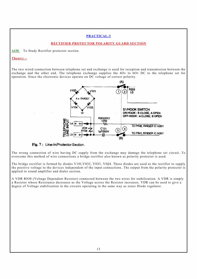
RECTIFIER PROTECTOR POLARITY GUARD SECTION
AIM To Study Rectifier protector section. Theory: - The two wired connection between telephone set and exchange is used for reception and transmission between the exchange and the other end. The telephone exchange supplies the 4Ov to 6Ov DC to the telephone set for operation. Since the electronic devices operate on DC voltage of correct polarity.
The wrong connection of wire having DC supply from the exchange may damage the telephone set circuit. To overcome this method of wire connections a bridge rectifier also known as polarity protector is used. The bridge rectifier is formed by diodes V10l,VlO2, VlO3, VlQ4. These diodes are used as the rectifier to supply the positive voltage to the devices independent of the input connections. The output from the polarity protector is applied to sound amplifier and dialer section. A VDR RlO8 (Voltage Dependent Resistor) connected between the two wires for stabilization. A VDR is simply a Resistor whose Resistance decreases as the Voltage across the Resistor increases. VDR can be used to give a degree of Voltage stabilization in the circuits operating in the same way as zener Diode regulator.

14
PRACTICAL-4
RINGER SECTION
AIM To Study Electronic Tone Ringer section. Theory: - Ringer circuit is made of the IC KA2418 and some other related components. The sound signal output from the pin number 5 of this IC drives a speaker. The output is provided to the speaker through a variable resistor R304 (l00K). This variable resistor controls the Volume of the ringer tone. A detailed working principle of the Ringer section is given next. In the ringer section pin no. I of the IC30 I (KA2418) is connected to one of the wires in the phone line thru C101 (1.0MFd/250V) and ringer switch in the telephone set. The other wire is connected to the pin no.8 of IC30 I (KA2418) thru R302 (2K2). When the receiver is on the cradle. Ringer switch is in on position. This makes the phone set to be connected to the 48V DC supply coning in the phone line. The capacitor C101 (1.0MFd/250V) in series to the two-way switch does not allow this supply to reach the ringer section. When the ring signal come as AC pulse from the exchange the capacitor allow the AC pulse to pass. This makes the pin I & 8 of IC KA2418 to receive the AC ringer pulse. This AC signal is converted into DC signals and then rectified and filtered by the IC KA2418. This rectified. Filtered DC signal goes to the output to the pin 5 of IC. The output from the pin 5 of IC KA2418 is sent to ringer/buzzer speaker thru a volume controller R304 (lOOK). This variable resistor can be used to increase or reduce the volume of the ringer. C301 (100KpF) connected in-between the pin 2 and 3 of the IC KA2418 is used to discharge the signals. Resistor R303 (15K) connected in-between the pin 2 and 4 of the IC KA2418 is used to set the ringing speed. The capacitor C302 (IOMFd/63V) connected to the pin no. 7 of the IC is used to filter the voltage inside the IC POLARITY GUARD The bridge rectifier made of the four Diode VRl01 to VR104 (4 x IN4004) acts as polarity guard or the polarity corrector (or this telephone circuit. This protects the electronic components of the telephone circuit from any change in the polarity of the input current. The wires incoming from the telephone exchange contain negative supply on one wire and positive supply on the other wire. If these signals are provided to the telephone equipment without rectification it could damage them. After rectification. one can connect any wire of the telephone line to any wire of the telephone set.

15
IC LS1240 (Ringer IC) This telephone model uses 8 pin IC LS1240 in the Ringer section. The description and usage of pins of IC are: Pin 1, 8 (Line In):
This pins are used to sense the ring signals from exchange. Pin 1 is connected through C101, on-hook/off-hook switch to the telephone line. Pin8 is connected through R302. The signals from telephone line are rectified by the internal bridge rectifier. Pin 2 (-Ve):
This is the negative supply pin, this pin is grounded. Pin 3 (Cont-C):
This is the sweep rate control pin connected to the capacitor 001. Pin 4 (Cont-R):
This is the oscillator frequency control input pin connected to the resistance R303. Pin 5 (O/P):
This pin outputs the ringer/tone signals to the buzzer/speaker through the volume control switch R304. Pin 6 (NC):
This pin is not connected in this set.
Pin 7 (Filter): This pin is connected to capacitor 002 as a filter to the internal DC.

16
PRACTICAL-5
VOLTAGE DROPPER SECTION
AIM To Study Voltage dropper Section.
Theory: - Current limiter or voltage dropper or switching circuit is made of a number of transistors.
When the receiver is picked up from the cradle it is the job of this sections to drop the 4BV DC supply available in the telephone line to the operating voltage range. Three series transistors. VR203 (MPS-A92). VR204 (2N6517) and VR205 (2N6517) work as voltage dropper in this circuit. These transistors also do the job of outputting the sound signal and the dialing pulse received from the sound amplifier section to the phone line. Following table gives voltages of these Transistors
A detailed working principle of the Current limiter or voltage dropper section is given next. The 48VDC signal incoming from the telephone exchange is received by the emitter of the VR203 (MPS-A92), thru. Polarity corrector circuit, cradle switch and R20 I (22 .Q). This supply is used to bias the base of VR203 thru R202 (l00K). This base is also connected to the collector of the VR205 (2N6517). Collector ofVR203 is defect connected to the base of VR204 (2N6517). Collector of NPN transistor VR204 (2N6517) receives same supply received by the emitter of VR203. Base of VR204 (2N6517) is directly connected to the emitter of VR203. Base of VR205 (2N6517), NPN transistor is connected to the positive supply line coming from the polarity corrector and the cradle switch thru R204 (560K). Base of this transistor is directly connected to the collector ofVR206 (BC546). Emitter of VR205 is directly connected to the ground and the collector is connected to the emitter ofVR203. When the base ofVR205 (2N6517) receives voltage from the telephone line, this transistor will start to conduct and output negative bias at the collector. This will turn on the VR203 (MPS-A92) and VR204 (2N6517). Switching on of these two transistors will drop the supply coming in from the exchange. VR203 (MPS-A92), VR204 (2N6517) and VR205 (2N6517) do the Job of regulating the supply as well as they do the Job of sending the sound signal and dialing pulse coming from the sound amplifier to the telephone exchange. In this voltage dropper section VR203 (MPS-A92), VR204 (2N6517) and VR205 (2N6517) are main three transistors. In these transistors VR203 and VR204 are known as regulator transistors. VR205 is known as voltage dropper transistor and, VE206 (BC546) is known as current limiter transistor.

17
So, the current limiter circuit does the Job of dropping or reducing the 48VDC to proper operating level. The telephone exchange supplies 40V to 60V DC to the telephone set for operation. But electronic circuit operates on 9V to 12V. Thus when the handset is off-hook position, this supply is applied to the electronic circuit for operation through the voltage dropper section. The transistors V206, V205, V203, V204, V208 are used to lower the line voltage and supply the regulated voltage to dialer and speech/sound amplifier section. The transistor V208 and V206 are regulator transistors. When the handset is in off-hook position, the supply from telephone line is applied to the base NPN transistor V205 through R205, emitter of PNP transistor V203 through R202, collector of NPN transistor V204. The transistor V205 switches ON. The low output from the collector of V205 to the base of PNP transistor V203 through R204 switches it ON. The high output from the collector of V203 to the base ofV204 switches it ON. The high output from the emitter is applied as the positive supply to sound amplifier IC pin 1 and also to dialer IC pin6 through RIO9, diode V210. The zener diode VIO5, V505 are used to bypass the overvoltage and capacitors CIO8, C202, CIO6, C508 are used as filter.
Regulation The regulator transistors v208 and V206 are connected in cascade mode. The high output from the emitter of V204 is applied to the base of V208 and collector of V208. When the input voltage increases the transistor V208 switches ON and the high output from the emitter to the base of NPN transistor V206 through R209 switches it ON. The transistor V206 bypasses the base biasing of transistor V205 for regulated output. Similarly when the input is low, the regulator transistor stays OFF for the regulated output from the emitter of V204.

18
PRACTICAL-6
DIALER SECTION
AIM To Study Dialer Section. Theory: -
The dialing circuit in this telephone is made of the IC UM912148 and some other related components. This IC has the facility to select tone or pulse dialing. In the pulse dialing mode. the number key pressed on the keypad to dial a number are decoded by this IC and based on the, pressed number this works as a pulse circuit. For the DTMF dialing the DTMF sound tones are provided by this IC to the sound amplifier IC TEAIO62A. from where this signal is amplified and passed on to the telephone line. A 3.58MHz crystal g201. is connected in between the pin 3 & 4 of the dialer IC. This crystal or ceramic resonator works as time base for the oscillator in the dialer IC. This helps the dialer IC to generate accurate DTMF signal as per the CCITT standard.
A detailed working principle of the Dialing section is given next. The number dialed by the key matrix of the keypad is converted in to tone or pulse dialing signal by the UM91214 in the dialing generator section. In the pulse-dialing mode based on the key being pressed. This IC generates number of on -off pulses. For example if you press number 4 on the keypad. Then this IC will send 4 on off signals to the telephone exchange.

19
These on off signals turn on and off 10 times in each second and there Is a delay of around I second between the on-off pulses of different numbers being dialed. This IC as facility to store up to 30-digit number dialed. This facility helps the phone user in redialing the last dialed number. For this the user can press the R (Redial) button on the keypad. Each new Number dialed will remove the old number from the memory. The dialing pulse coming out of the pin no. 1 of dialing UM91214 goes to the telephone exchange through VR207 (BC546). Pin no. 2 of the dial IC UM91214 is used to select pulse or tone mode of d1al1ng. A two-way switch on this pin selects the dialing mode to be used. Pin no. 3 and 4 of the d1al1ng IC UM91214 are oscillator pins. Both of these pins are grounded thru C202 (33pF) and C203 (33pF) respectively. A crystal Q201 (3.58MHz) is connected between these two pins. Pin no. 5 of this IC gets negative supply and the pin no. 6 gets the positive supply. Pin no. 8 of the IC UM91214 sends out the pulse or tone signal of the dialed number. This signal goes to the sound amplifier section. Where it is ampl1fted and sent to the speaker. Pin no. 11 of the IC UM91214 is used to cut off the dial tone signal. This dial tone signal comes to us from the telephone exchange. When we pickup the handset to dial a number. this dial tone must cut off after a number Is pressed on the keypad. Otherwise we will not be able to dial a number. Once the dial tone cut signal from the pin no. 11 of the IC; UM91214 reaches the exchange. Exchange will cut off the dial tone signal. At this same time the number dialed on the phone stets will reach the exchange. IC UM91214B (Dialer IC) This telephone model uses 18 pin IC UM91214B in the dialer section for dialing signals and storing the number for redial. The description and usage of pins of IC are:
Figure-l shows pin on figuration of this IC. Pin 1 (DP) : This pin generates the dialing pulses to the exchange through telephone line.
Pin 2 (MODE IN) : This pin is used for dial mode setting. The external Tone/Pulse switch is connected to this pin for dial mode setting.

20
Pin 3, 4 (OSC) : The 3.58MHz external crystal oscillator is connected between this pins to generate the clock/pulse frequency.
Pin 5 (GND) : This is ground pin. Pin 6 (Vdd) : This is the positive supply input pin.
Pin 7 (Int. Cct) : This pin used for internal control circuit with sound amplifier section.
Pin 8 (Dial Tone Out) : This pin generates the dialing tone and pulses to the speaker through sound amplifier IC.
Pin 9 (Line ON) : This pin is not connected in this set. Pin 10 : This pin is not connected in this set.
Pin 11 (Dial Tone Cut Signal) : This pin supplies the dial tone cut signal while dialing a number from keyboard.
Pin 12, 13, 14 (Cl, C2, C3) : These are the column signal input pins. When a button on the keypad is pressed a row and a column is shorted for the signal to one of this pin to indicate that a button is pressed. Pin 15,16,17,18 (Rl, R2, RJ, R4) : These are the row signal input pins. When a button on the keypad is pressed a row and a column is shorted for the signal to one of this, pin to indicate that a button is pressed.
This BEETEL model operates either in Pulse or Tone/DTMF mode. The mode set signal is applied to pin2 of dialer IC through the Tone/Pulse mode switch. High signal on this pin indicates pulse mode dialing. The dialer section is controlled by 18 pin OIL IC UM 91214 B. The dialer IC can store a 20 digit long number last time dialed from the same set for redialing. When the handset is in off-hook position the hook switch pin 1 is in contact with pin2, the speech and dialer sections are enabled. The positive supply from emitter of regulator transistorV204 is applied to pin6 through R109 and diode 0210. The 3.58MHz external crystal oscillator G201 is connected between pin3 and 4 of IC to generate the pulses/frequency. The pins 12, 13 and 14 are connected to the each column and pins 15, 16, 17, 18 are connected to each row of key matrix. When the handset is in off-hook position the dial tone from exchange is applied to the speaker, when a dial key is pressed the dial tone cut signal is generated from pin 11 of dialer IC. When a key is pressed a row and a column is shorted to indicate the dialer IC that a key is pressed. The IC generates the pulses/frequency according to the mode set by the Tone/Pulse switch. The signals from pin l of dialer IC are applied to telephone line through V207, R219, ringer switch and rectifier for making a telephone call. The exchange counts the number of pulses to make the contact.

21
When a key is pressed the dial pulses from pin1 are also applied

22
PRACTICAL-7
KEYBOARD MATRIX SECTION
AIM To Study Keyboard Matrix Section.
Theory: - The key-matrix arrangement of is shown In the figure below. This complete matrix with the LED on the keyboard is connected to different pins of the ICUM91214. Pressing of different keys on the key-matrix. shorts different pins of the IC. This makes this dialing IC to generate different combination of on and off pulses on the phone line. The Key arrangement on the keypad is as shown next.
All the buttons on this keypad are connected to each other thru horizontal and vertical connections. Horizontally following connection is found on the keypad. .

23
Connection no. 2 is connected to the keys 1. 2 and 3 push buttons. Connection no. 9 is connected to the keys 4. 5 and 6 push buttons. Connection no. 6 is connected to the keys 7.. 8 and 9 push buttons. Connection no. 7 is connected to the key. And the connection 4 is connected to 0 and # push buttons. Vertically following connection is found on the keypad. Connection no. 3 is connected to the keys 3.6. 9 and # push buttons. Connection no 5 are connected to the keys 8 and 0 push buttons. Connection no. 10 is connected to the keys 3 and 5 push buttons. Connection no. 8 is connected to the keys 4.7 and. push buttons. Connection no. Is connected to the key I. Pin 18 of the dialer IC OM 91214 is connected to the R (redial) button. When different keys are pushed on the keypad. Different set of connections gets shorted. This informs to the dialing IC about the key being pressed on the keypad. The following table shows the connections getting shorted on pressing different keys.
24
Numbers 0 to 9 on this keypad is used to dial different numbers. The R button is used to redial the last dialed number. The (astrix or star) button is used to turn the phone into tone dialing mode. When this button is pressed the telephone will start operating in the tone-dialing mode. This BEETEL model has 12 buttons on the dial pad (0, 1, 2, 3, 4, 5, 6, 7, 8, 9, #, *) arranged in four rows and three columns such that every button is related to only one row and one column. When a button on the keyboard is pressed, a row and a column is shorted for a signal to indicate the dialer circuit that the button between the row and the column is pressed. In the above fig. If button '1' is pressed the row R1 connected to pin15 of dialer IC and the column C3 connected to pin14 of IC are shorted to indicate that the button' 1 ' connected between R 1 and C1 is pressed. The dialer section generates the number of pulses in one second (frequency) to the exchange according to the button pressed and the dial mode set by the Tone/Pulse switch. The telephone exchange counts the number pulses and makes the contact with that number.

25
PRACTICAL-8
SPEECH AMPLIFIER SECTION
AIM To Study Speech Amplifier Section. Theory: -
The reception and transmission of sound signal is controlled by the IC TEAIO60 in this telephone. A microphone is used as transmitter and a speaker is used as receiver. A mute signal from the dialer IC mutes this amplifier during the dialing operation. This stops any clicking sound normally heard during the dialing operation. The main jobs of this circuit are. The input received from the microphone/mouthpiece is amplifier and provided to exchange through the telephone Line. The signal coming in the telephone line is amplifier and provided. to the speaker. Dial-tone signal coming in from the dialing generator section of the exchange is amplifier and provided to the speaker. Let us see the pin description of this sound amplifier IC TEAIO62

26
A detailed working principle of the Speech and Sound Amplifier section is given next. After receiving the ring signals, when the handset is switched from on-hook to off-hook position the audio/speech signals from telephone line are applied to the speech/sound section IC pin13 through voltage dropper. These signals are amplified by sound amplifier and applied from pin4 to the speaker for audio output through C121. The capacitor C121 stops the DC bias to the speaker. The capacitor C112, Cl17, Cl04 are used as the filter for spikes. Similarly the signals from the microphone are applied to microphone amplifier pin6 and pin7 through R111, R110. The amplified signals from pin13 are applied to the telephone line for transmission through voltage dropper, ringer switch and polarity protector. These amplified signals are also applied to AGC for level control. The dial tone from pin8 of dialer IC is applied to pin12 of sound amplifier IC. This dial tone is amplified and from pin4 is applied to the speaker for dial/tone signal. Similarly when a key is pressed the dial pulses from pin 1 are applied to the telephone line through the V207, protector, ringer switch and rectifier. Similarly the dial pulses are also applied to the speaker through V207, dropper section and sound amplifier IC pin4. The pin no. 6 and 7 of the IC TEAl062 are input pins. The mouthpiece or the microphone of the receiver is connected to these pins of the IC. The microphone is connected to the pin no. 6 & 7 of the IC TEAl062 thru Rll0 (560 Q) and Rill (560 Q). These resistors are used for impedance matching of the microphone and the IC. Cl16-Cl17 (2K2pF) are used to filter the signals. The audio at the microphone is converted into electrical signals by the microphone. These signals are provided to the pin no. 6 and 7 of the IC TEAl062 thru Rll0-Rlll (560Q). This signals are amplified by the IC and provided at the output pin no. 13. Cl09 (220pF) connecting pin no. 13 to the ground is used for signal filtration. C 1 08 (220MFdj25V) is used to separate the supply and for filtration. The signal at pin no. 13 is the audio signal spoken by us at the microphone. This signal is sent to the exchange thru the telephone line and the voltage dropper section, Rl09 (6200), VR204 (2N65l7) and VR203 (MPS-A92). Thru the exchange this signal reaches the telephone instrument of the number dialed by us.

27
When someone else calls use, the signal reaches the pin no. 13 of the sound amplifier IC, thru the polarity corrector and the voltage dropper section. This signal is amplifier by the IC and provided as output at the pin no. 4. This signal at the pin no. 4 is sent to the speaker thru CI02 (IOMFd/63V) and RI03 (82,Q). Speaker converts this signal into audio and we are able to hear the person at the other end of the phone. Different components at the pin no. 4 are used for different purpose. The C 1 02 (10MFd/63V) stop any DC bias signal present in the AC signal being sent to the speaker. The RI03 (82,Q) is used for impedance matching of the speaker. C 117 (2K2pF) is used for filtration of the signal at the pin no.4. CI03 (100pF) and RI04 (5200) in between the pin 4 and 5 are used to complete the internal circuit of the IC. C104 (1KpF) at the pin no.5 of IC TEAl062 is used for filtration. The pulse or tone dial signal from the pin no.8 of the dialing IC UM9l214 is directly provided to the pin no. 12 of the sound amplifier IC TEA 1 062. R 1 02 (120K) is used at the pin no.12 to bias the supply. This signal is amplified by the IC and provided as output at the pin no.4. From the pin no.4 this signal is provided to the speaker and we hear the dial tone on the speaker. R116 (3K6) between the ground and the pin no.8 of IC TEA 1 062 is used for negative bias. Cl18 (l00KpF) in between pin no. 10 and 16 and C204 (1OOKpF) on pin no. 11 are used to complete the internal circuit of the IC. C107 (120pF) in between the ground and pin no.l0 of the IC is used for filtration. C111 (4.7MFd) at pin no. 14 is used as filter for the internal circuit. Various components RlI9(330Q),Rl06(3K9), Rl07(220Q), R12l(390W), Cll9(330pF), C110(I00pF) and RI08520W) are used in the circuit to complete the internal circuit of the IC. Pin no. 15 of the IC TEAl062 is not connected to the circuit. Pin no. 1 of the IC TEAl062 receives positive supply from the emitter of the VR204 (2N6517) in the voltage dropper section. VRl05 connected to the pin no l keeps this supply voltage stabilized and Cl00 (l00pF) is used for filtration. Pin no. 9 'of the IC TEA 1 062 is used for negative supply and this pin is directly connected to the ground.

28
IC TEAIO62A
(Speech/Sound Amplifier IC) This telephone model uses 16 pin OIL IC TEA1062A in the speech/sound amplifier section. The description and usage of pins of IC are:
Pin 1 (Vcc) :
This is the positive supply input pin. When the handset is in off-hook position this pin receives the regulated supply from the voltage dropper circuit.
Pin 2, 3, 5, 10, 11, 14, 16 (Int. Cct) : This pins are used for internal operations.
Pin 4(Sound O/P):
This pin supplies the audio/dial tone signal to the speaker. Pin 6, 7 (MIC. IN):
These pins are connected to the handset microphone for input speech/audio signals from microphone. Pin 8 (Vss):
This is the negative supply input pin.
Pin 9 (GND) : This is ground pm.
Pin 12 (Dial Tone) :
This pin receives the dial tone signal from dialer IC. Pin 13 (Sound I/O) :
This pin is used for receiving and transmitting the audio signals from telephone line. Pin 15 (AGC) : This pin is used for automatic gain control.

29
PRACTICAL-9
OPERATIONAL PROCEDURE
AIM To understand and perform operational procedure. Theory: - FEATURES:
1. Key-lock 2. Ringer with adjustable volume 3. Tone Pulse Switchable 4. Redial (can store up to 31 digits) 5. Mute 6. Flash 7. Pause
INSTALLATION AND CONNECTION: Connect the Plug of the line cord with the Telephone line through the line jack unit.
Pick up the handset, keep Hook on/Off switch to Off Hook position and listen to the dial tone. Your phone is now ready to use. HOW TO USE TELEPHONE: This is a TONE/PULSE Switchable telephone, which can be used to access both types of exchanges i.e. Pulse dialing (Loop Signaling) and Tone dialing (DTMF signaling). The telephone can be set to either of the two signaling modes through the T/P switch. The phone is capable of switching dynamically to the Tone Mode, while operating in pulse Mode, by pressing" * " key. LAST NUMBER REDIAL: Your phone remembers the last number dialed. Simply press the hook switch to get the dial tone followed by pressing the REDIAL key. Your number will be automatically redialed. RINGER VOLUME CONTROL SWITCH: For a soft ring, set the switch to position M, for louder ring, set the switch to position H. For low Ringer volume, set the switch to position L. PAUSE: Allow you to access dial toile of second exchange while redialing a number, when connected- behind an EPABX. A pause can be entered into the dialing sequence by pressing the PAUSE button. MUTE: As long as MUTE button is kept pressed no Speech will be transmitted to the other party. FLASH: The FLASH button can be used for call waiting. It may be used to access facilities offered by some EPABXs or Network services provided by the telephone company. KEY-LOCK: Your phone is equipped with mechanical lock to activate/inactivate the dialing circuit. When in lock position, you will not be able to dial any number.

30
PRACTICAL-10
TEST POINT VOLTAGES FOR DIFFERENT SECTIONS
AIM To measure Test Point Voltages for different sections. Theory: - V1. Voltage Measurements: 1.On Hook: Line Voltage: 26 Volt DC 2.OFF Hook: Line Voltage: 8 Volt DC V2. Dial Tone O/P Voltage In Pulse Mode: (Line O/P) 1.While Dialing the number: 20 Volt DC 2.When Not Dialing the number: 8 Volt DC V3. Dial Tone O/P Voltage In Tone Mode: (Line O/P) 1.While Dialing the number: 8 Volt DC 2.When Not Dialing the number: 8 Volt DC

31
PRACTICAL-11
TEST POINT WAVEFORMS FOR DIFFERENT SECTIONS
AIM To observe Test Point Waveforms for different sections. T1. Dialer Section: Dial tone in dialer section – IC HT93214A: (Crystal 3.58MHz) Tone Mode Dial tone - Pin 3 / 4)
Pulse Mode Dial tone – Pin 3 / 4
T2. Ringer Output From IC 1: KA2418 Buzzer Output Pin-5: (When Ring Comes)
T3. While Dialing Number: (In Tone Mode) (IC HT93214A -At Pin 3 / 4)
Vout=0.7VPP Freq=3.5MHz
Vout=0.7VPP, 0.5VPP Freq=3.5MHz
Vout=12VPP Freq=1 KHz
Vout=0.7VPP Freq=3.5MHz

32
T4. While Dialing Number: (In Pulse Mode) (IC HT93214A -At Pin 3 / 4)
Vout=0.7VPP, 0.5VPP Freq=3.5MHz

33
PRACTICAL-12
DIFFERENT TYPES OF FAULTS
AIM To understand faultfinding methods for different types of faults. Theory: - Fault No.1. The telephone set is dead.
- Check the telephone line wires connection and the voltage from exchange, polarity protector diodes, Ringer/on-hook/off -hook switch.
- Check the dropper circuit, transistor V205, V203, V204, V206, V208, Diode V2l0 zener Vl05, V505,
Capacitor Cl06, Cl08, CSO8, Cl09, Cl0l, Cl12,
- Check the speech/sound amplifier section for dial tone; check speaker and microphone connections, C12l, Cl17, Cl04, microphone connections C.1l5, C.1l6.
- Check ringer IC connections.
Fault No.2. No ring signal from telephone set.
- Check on-hook/off-hook switch and telephone connections and voltage.
- Check ringer IC 1.S1240, pin 1 and 8 telephone line connections, volume control potentiometer R304.
- Check Cl0l, C30.1, C302, and R303, speaker connections. Fault No.3. Continuous ringing from telephone set.
- Check ringer IC 1.S.1240, Check capacitor C30l connected to pin3 of ringer IC. Fault No.4. No dialing/wrong number dialing from telephone set.
- Check the dropper circuit, transistor V205, V203, V204, V206, V208, Diode V2lO zener V.105, V505, Capacitor Cl06, Cl08, C508, Cl09, Cl0l, Cl12,
- Check on-hook/off-hook switch and the supply at pin6 of dialer IC, Y2l0, Vl05, V505.
- Check CZO5, C-i.O6, crystal G20l connected between pin3 and 4 of dialer IC.
- Check keypad switches.
Fault No.5. No audio signal transmission or receiving.
- Check the dropper circuit, transistor V205, V203, V204, V206, V208, Diode V2lO zener VlO5, V505,
- Check sound amplifier IC, speaker and microphone connections.
- Check Cll7, C.104, C12l, Cl12, Cl16, C.1l5, CZO1, CZO4, Cl07, Cl.18, C.1.1l, ClO8, CSO8, C.1l9.
- Check sound amplifier IC.

34
Fault No.6. No audio signal transmission or receiving, only incoming ring signals are heard.
- Check the telephone line wire connections and the voltage from exchange, polarity protector diodes,
and ringer switch. - Check the dropper circuit, transistor V205, V203, V204, V206, V208, Diode V2lO zener V.105,
V505,
- Check sound amplifier IC, speaker and microphone connections.
- Check Cl17, Cl04, C121, Cl12, Cl16, Cl15, C201, C204, Cl07, Cl18, C111, Cl08, CS08, Cl19.
- Check sound amplifier IC. Fault No.7. No ringer sound from telephone set.
- Check capacitor Cl01, C301, C302, hook switch, R303, volume control switch R304, speaker.
- Check ringer section by applying external 4OV AC signal through hook switch, if there is no output then Replace the ringer IC LS1240.
Fault No.8. Low ringer sound at maximum volume.
- Check the telephone wires, capacitor Cl0l, and hook switch, ringer volume control switch. - Replace ringer IC LS1240.
Fault No.9. Intermittent ring signals i.e. some times the ringer sound output is available and sometimes not.
- Check the hook switch, clean the contacts. - If there is no output then check the ringer section components. - Replace ringer IC.
Fault No.10. Incoming Ring signals are available but not sound from the caller. - Check hook switch, voltage dropper transistors V205, V203, V204, V206, V208, Diode V210
zennerVl05, V505.
- Check speaker connections, filter capacitors Cl17, C121, Cl12, Cl04
- Replace sound amplifier IC TEA1062A. Fault No.11. Incoming Ring signals are available but not sound to the calling party.
- Check microphone connections, filter capacitors C115, Cl16, Cl06, Cl08, CSO8, Rl11, Rll0
- Check hook switch, voltage dropper transistors V205, V203, V204, V206, V208, zener Vl05, V505.
- Replace sound amplifier IC TEAI062A.

35
Fault No.12. Ring sound is available but cannot dial the number.
- Check positive supply to dialer I Cat pin6, filter capacitor C202, zener V505, diode V210.
- Check keypad switches, tone/pulse switch.
- Check crystal oscillator G201, filter capacitor C205, C206.
- Check dial pulse signal from pin 1 of dialer IC, filter capacitor C203, V207, hook switch, polarity
protector diodes, telephone line connections. Fault No.13. Continuous dial tone available and no dialing.
- Check dialer IC UM91214, positive supply to dialer IC at pin6, filter capacitor C202, zener V505,
diode V2l0. - Check dial tone cut signal from pin 11, dial tone cut transistor V208, R208, R209, R206.
- Check keypad switches, tone/pulse switch. - If no signal available at pin 1 of dialer IC on pressing a key then replace dialer IC.
Fault No.14. Telephone set operates only on pulse dial mode i.e. no operation tone dial mode.
- Contact telephone exchange whether it has the facility of tone dialing.
- Check tone/pulse switch connected to pin2 of dialer IC, positive supply to dialer IC at pin6, filter
capacitor C202, zener V505, diode V2l0.
- Check crystal oscillator G20l connected between pins 3 and 4, filter capacitor C205, C206.
- Replace dialer IC UM912l4. Fault No.15. Telephone set operates only on tone dial mode i.e. no operation pulse dial mode.
- Check tone/pulse switch connected to pin2 of dialer IC, positive supply. To dialer IC at pin6, filter
capacitor C202, zener V505, diode V2l0.
- Check crystal oscillator G20l connected between pins 3 and 4, filter capacitor C205, C206.
- Replace dialer IC UM91214. Fault No.16. Gets wrong number when a number is dialed.
- Check keypad buttons.
- Check keypad connections to the dialer IC. - Check the transistor V207, C203. - Check crystal oscillator G20l, capacitor C205, C206.
- Replace dialer IC UM91214.

36
Fault No.17. Ringer sound is available for incoming Call; number dialing is also possible but no audio sound available.
- Check voltage dropper transistors V205, V203, V204, V208, V206, zennerVI05. - Check speaker and microphone connections. - Check filter capacitors - Check C117, C104, C121, C112, Cl16, Cl15, C201, C204, CI07, Cl18, Cl11, CI08, CSO8, Cl19. - Replace sound amplifier IC TEA1062A.
Fault No.18. Low audio/sound from speaker.
- Check speaker connections, faulty speaker. - Check capacitor Cl17, C121, Cl12, C104, Rl12, R104.
- Check positive supply at pin 1 and input at pin13 of sound amplifier IC.
- Check replace sound amplifier IC.
Fault No.19. Low audio/sound from microphone to the other end.
- Check microphone connections, faulty microphone. - Check capacitor Cl16, Cl15, R111, R110 - Check positive supply at pin l and input at pin 13 of sound amplifier IC, Check dropper transistors,
Polarity diodes. - Replace sound amplifier IC.
Fault No.20. Noise in the audio/sound from speaker similarly the audio with high noise to the other end.
- Check speaker connections, filter capacitors Cl17, C121, C112, C104 - Check microphone connections, filter capacitor Cl16, Cl15. - Check filter capacitors Cl17, C104, C121, Cl12, Cl16, Cl15, C201, C204, CI07, C118, C111, CI08,
CSO8, Cl19. - Replace sound amplifier IC.

37
PRACTICAL-13
DATA SHEETS OF ICS USED IN TELEPHONES
AIM To study Data Sheets of ICs used in telephones.

38

39

40

41