30” Freestanding Electric Range Specification 2007.02 Smart Oven R&D Group System Cooking Business...
112
30” Freestanding Electric Range Specification 2007.02 Smart Oven R&D Group System Cooking Business Team FTQ386LWUX
-
Upload
anabel-blair -
Category
Documents
-
view
214 -
download
0
Transcript of 30” Freestanding Electric Range Specification 2007.02 Smart Oven R&D Group System Cooking Business...

30” Freestanding Electric Range Specification
2007.02Smart Oven R&D Group
System Cooking Business Team
FTQ386LWUX
1. Product Summary
2. Concept & Features
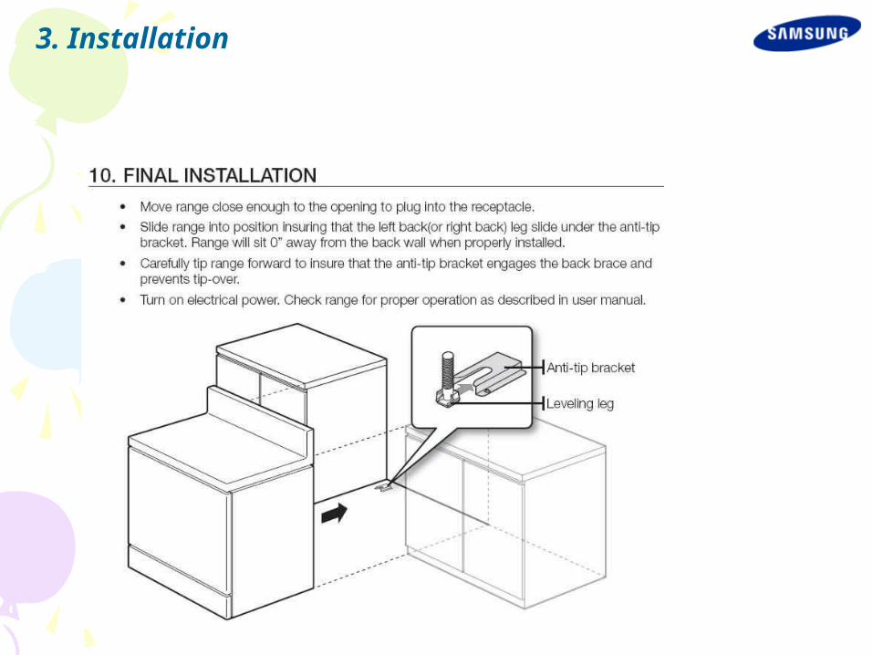
3. Installation
4. Alignment and Adjustments
5. Assembly & Reassembly
6. Trouble shooting
7. Function
8. Schematic Diagrams
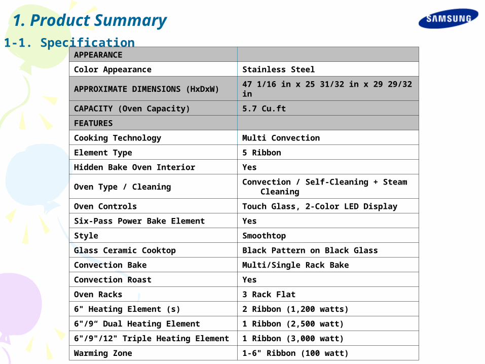
1. Product Summary1-1. Specification
APPEARANCE
Color Appearance Stainless Steel
APPROXIMATE DIMENSIONS (HxDxW) 47 1/16 in x 25 31/32 in x 29 29/32 in
CAPACITY (Oven Capacity) 5.7 Cu.ft
FEATURES
Cooking Technology Multi Convection
Element Type 5 Ribbon
Hidden Bake Oven Interior Yes
Oven Type / CleaningConvection / Self-Cleaning + Steam
Cleaning
Oven Controls Touch Glass, 2-Color LED Display
Six-Pass Power Bake Element Yes
Style Smoothtop
Glass Ceramic Cooktop Black Pattern on Black Glass
Convection Bake Multi/Single Rack Bake
Convection Roast Yes
Oven Racks 3 Rack Flat
6" Heating Element (s) 2 Ribbon (1,200 watts)
6"/9“ Dual Heating Element 1 Ribbon (2,500 watt)
6"/9"/12" Triple Heating Element 1 Ribbon (3,000 watt)
Warming Zone 1-6" Ribbon (100 watt)
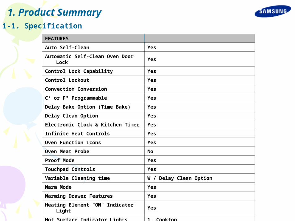
1. Product Summary1-1. Specification
FEATURES
Auto Self-Clean Yes
Automatic Self-Clean Oven Door Lock Yes
Control Lock Capability Yes
Control Lockout Yes
Convection Conversion Yes
C° or F° Programmable Yes
Delay Bake Option (Time Bake) Yes
Delay Clean Option Yes
Electronic Clock & Kitchen Timer Yes
Infinite Heat Controls Yes
Oven Function Icons Yes
Oven Meat Probe No
Proof Mode Yes
Touchpad Controls Yes
Variable Cleaning time W / Delay Clean Option
Warm Mode Yes
Warming Drawer Features Yes
Heating Element "ON" Indicator Light Yes
Hot Surface Indicator Lights 1, Cooktop

1. Product Summary1-1. Specification
FEATURES
Oven "ON" Light Auto
Oven Interior Light Yes
Self-Cleaning Cycling Light Display
Control Location Backsplash
Removable Full-Width Warming Drawer Yes - Warming Drawer
WEIGHTS & DIMENSIONS
Approximate Shipping Weight 220 lb (100kg)
Cabinet Width 30 in
Net Weight (lbs.) 194 lb (88kg, Included Accessary)
Overall Depth 25 31/32"
Overall Height 47 1/16"
Overall Width 29 29/32"
Oven Interior Dimensions (W x H x D) (in.)
25" x 20 25/32" x 18 15/16"
POWER / RATINGS
KW Rating at 208V 9.3
KW Rating at 240V 12.6
ACCESSORIES
Cooktop Cleaning Cream & Sponge Included
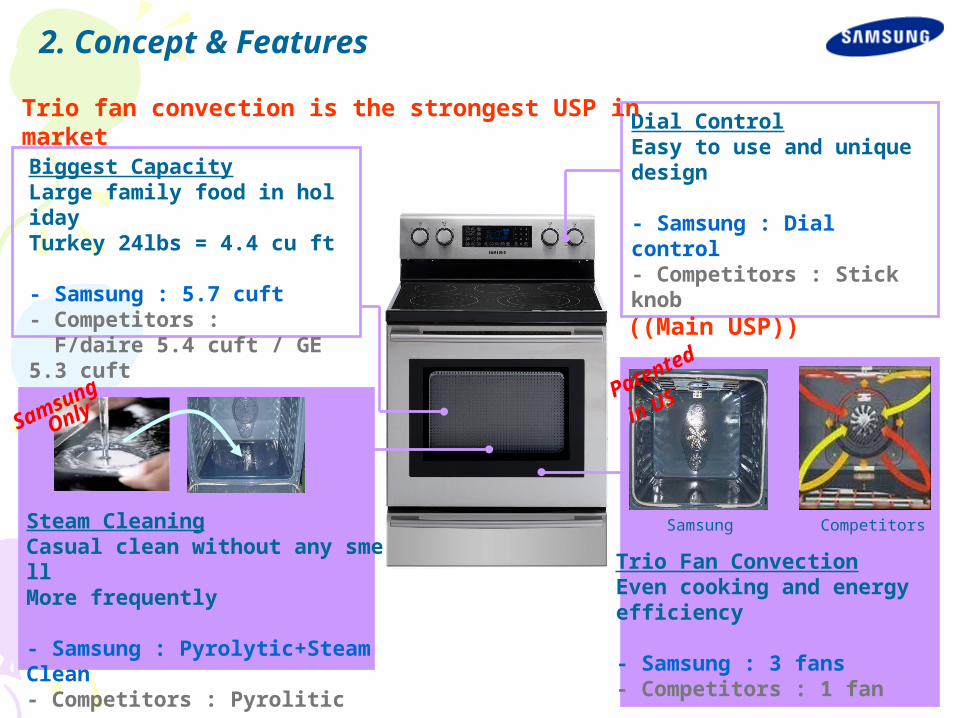
2. Concept & Features
Steam CleaningCasual clean without any smellMore frequently
- Samsung : Pyrolytic+Steam Clean- Competitors : Pyrolitic
Biggest CapacityLarge family food in holidayTurkey 24lbs = 4.4 cu ft
- Samsung : 5.7 cuft- Competitors : F/daire 5.4 cuft / GE 5.3 cuft
Dial ControlEasy to use and unique design
- Samsung : Dial control- Competitors : Stick knob
Trio Fan ConvectionEven cooking and energyefficiency
- Samsung : 3 fans- Competitors : 1 fan
Samsung Competitors
Patented
in US
Samsung
Only
Trio fan convection is the strongest USP in market
((Main USP))
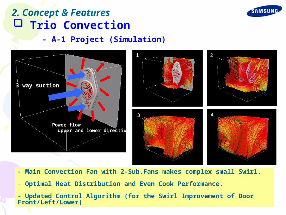
Trio Convection - A-1 Project (Simulation)
2
4
3 way suction
Power flow upper and lower direction
1
3
2
3 4
- Main Convection Fan with 2-Sub.Fans makes complex small Swirl.
- Optimal Heat Distribution and Even Cook Performance.
- Updated Control Algorithm (for the Swirl Improvement of Door Front/Left/Lower)
2. Concept & Features

Trio Convection (Comparison)
- GE (One Fan Convection Simulation)
2
1 way
suction
Power swirl around casing
2
43
1
- Single Fan makes Big Swirl- Uneven Cook Performance
2. Concept & Features

Trio Convection (Cook Performance Comparison) - Optimal Heat Distribution for Better Even Cooking - Samsung has a Goal Plan on Cooking Performance (3.5↑)
Items ConditionCompetitors
(1 Fan)FTQ386LWU
XRemark
Biscuits
1 level large cooking
2.0 3.0 -Rack : 3 or 4
2 level multi cooking
3.0 3.5 -Rack : 2 and 5
3 level multi cooking
2.0 3.0-Rack : 2,4 and 6
Large cooking using big tray
Competitors SAMSUNG
2. Concept & Features

Easy Steam Cleaning - More Efficiency & Time Saving - Available for Water and Oven Washing Liquid (Water + Detergent) - Takes about 20 minutes to Clean-out easily - Steam fits Light and frequent cleaning, (Pyrolytic Self-cleaning fits Greasy dirt cleaning)
Item Steam Clean
How to Use
• Pour the water10 oz. (+detergent)• Push the steam cleaning button• In around half min, the oven will stop automatically.• Wipe it out with wet cloths.
Operating (Temperature
)About 70 ℃
Operating Time
20 Minutes
Used Heater Bottom Baked HeaterSmell No smell
Tool to clean Wet cloths
2. Concept & Features

Biggest Capacity - The biggest capacity in current US market !!! - It benefits consumers to cook for large family food in Thanksgiving & Christmas seasons ( i.e Turkey 25 lbs = 4.4 cu ft, 20 lbs = 3.5 cu ft)
Samsung L/G Whirlpool GE Frigidaire Kenmore
FTQ386LWUX
LSC5622 GR448JBP84SKS
SFEFB89EC 96412
Cavity Capacity (Actual & Usable)
Communication 5.70 5.60 4.80 5.30 5.40 5.40
Actual Oven Capacity
5.70 5.59 4.74 5.24 4.60 5.31
Usable Oven Capacity
4.19 4.08 3.113.904.09
(Sump)3.87
3.934.11
(Sump)
Drawer Capacity (Actual & Usable)
Actual Oven Capacity
1.39 1.20 1.68 1.05 1.25 1.22
Usable Oven Capacity
0.96 0.89 1.13 0.96 0.71 1.00
2. Concept & Features

Design Identity (Package Design)
2. Concept & Features

BetterBest Better _ colorOvenSTSS Knob Black _ Knob
2. Concept & Features
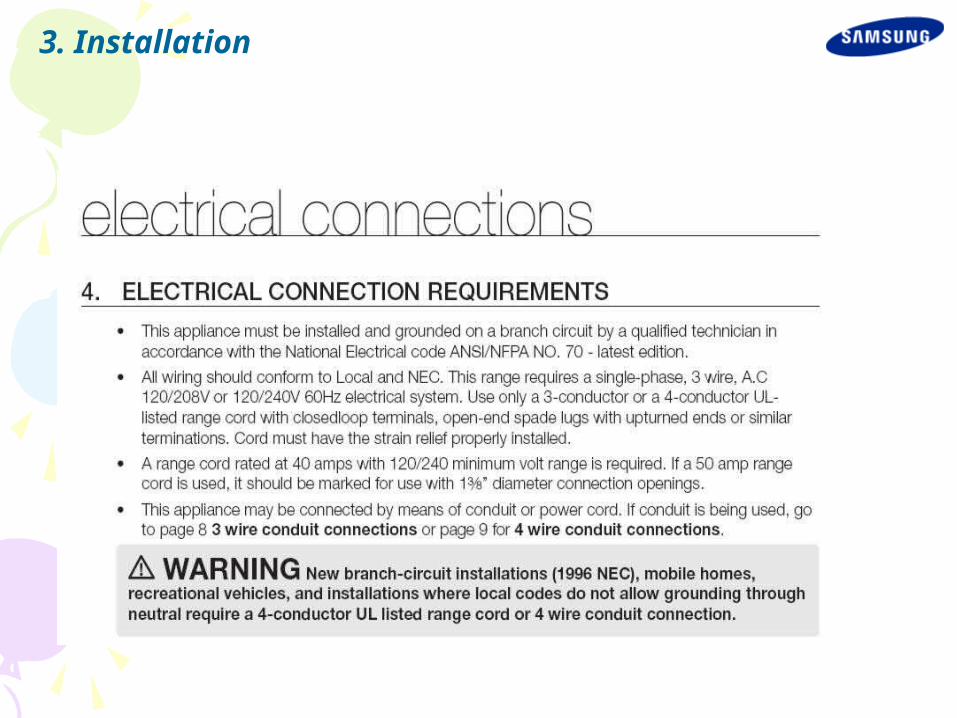
3. Installation
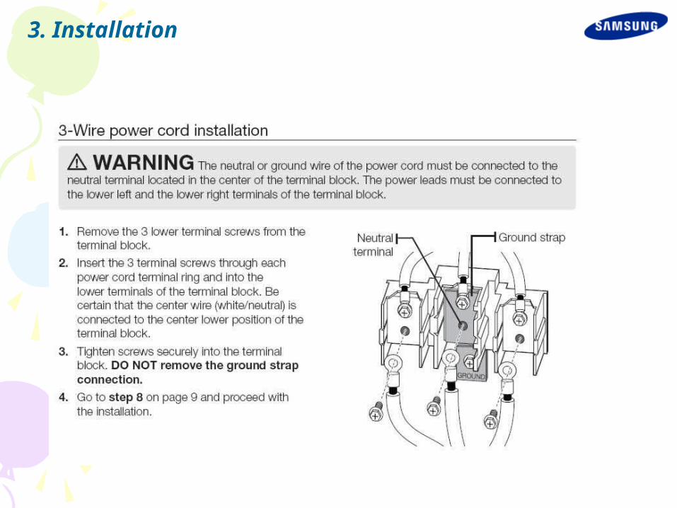
3. Installation

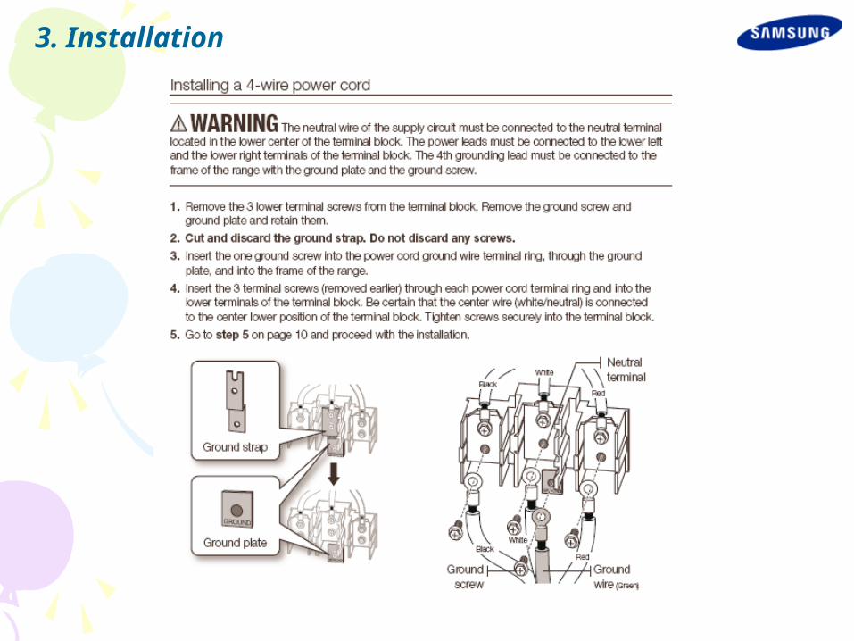
3. Installation
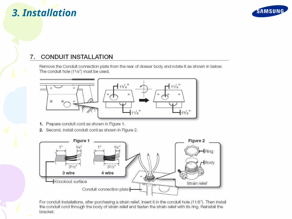
3. Installation
3. Installation
3. Installation

3. Installation

3. Installation
3. Installation
3. Installation
3. Installation
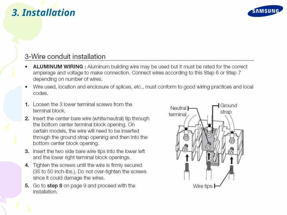
3. Installation
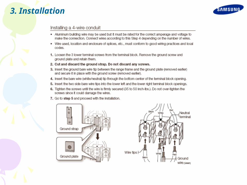
3. Installation
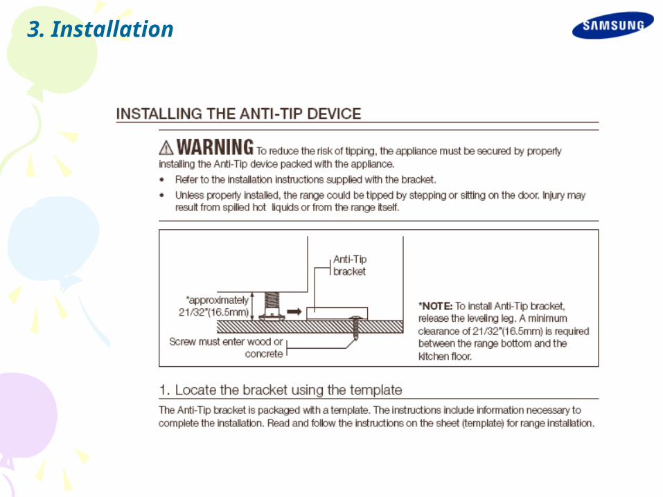
3. Installation
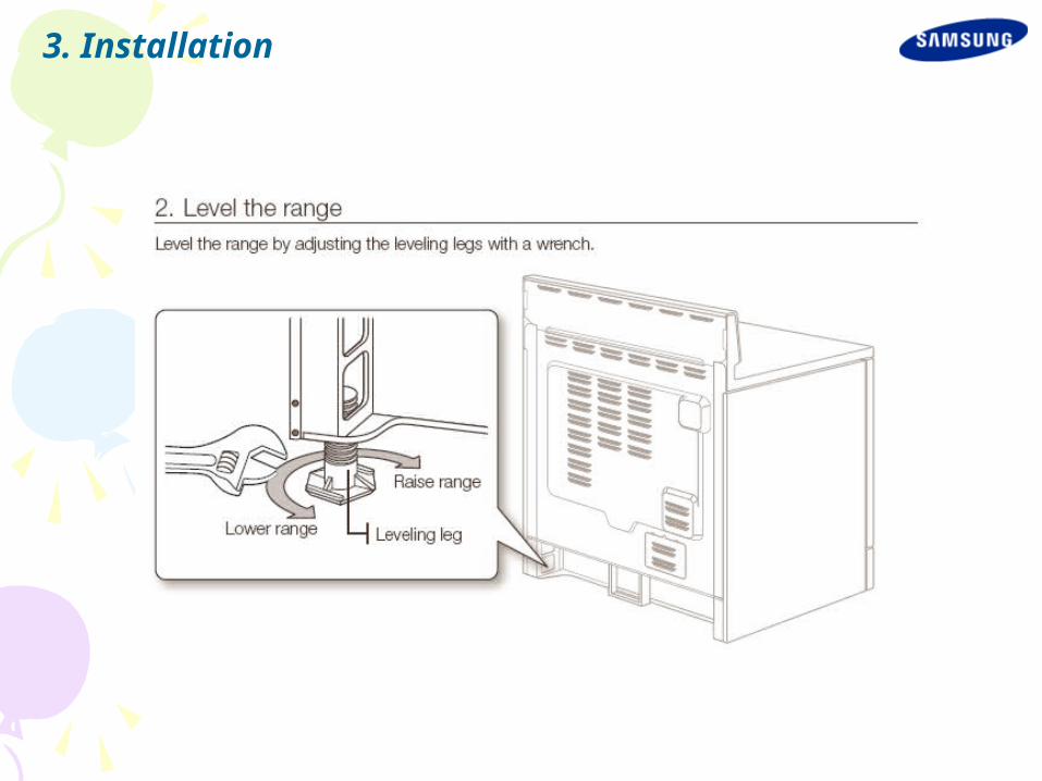
3. Installation

3. Installation
3. Installation

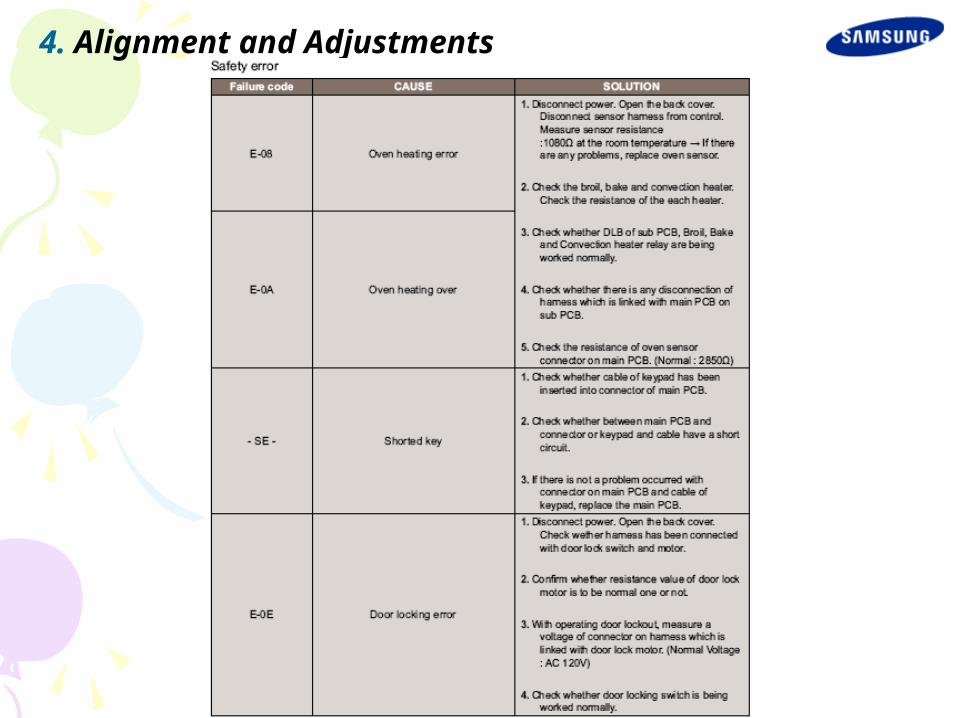
4. Alignment and Adjustments
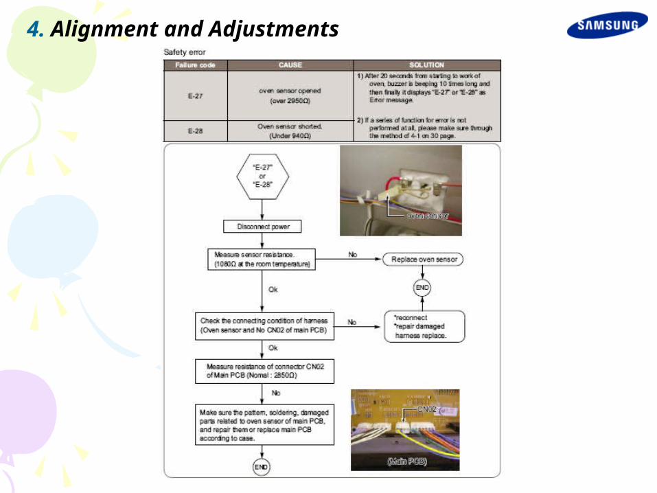
4. Alignment and Adjustments
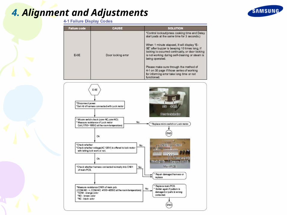
4. Alignment and Adjustments

4. Alignment and Adjustments

4. Alignment and Adjustments
4. Alignment and Adjustments

4. Alignment and Adjustments
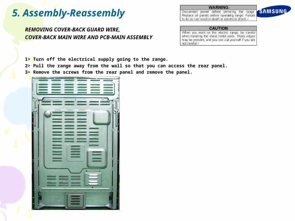
5. Assembly-Reassembly
REMOVING COVER-BACK GUARD WIRE,
COVER-BACK MAIN WIRE AND PCB-MAIN ASSEMBLY
1> Turn off the electrical supply going to the range.
2> Pull the range away from the wall so that you can access the rear panel.
3> Remove the screws from the rear panel and remove the panel.
REMOVING COVER-BACK GUARD WIRE,
COVER-BACK MAIN WIRE AND PCB-MAIN ASSEMBLY
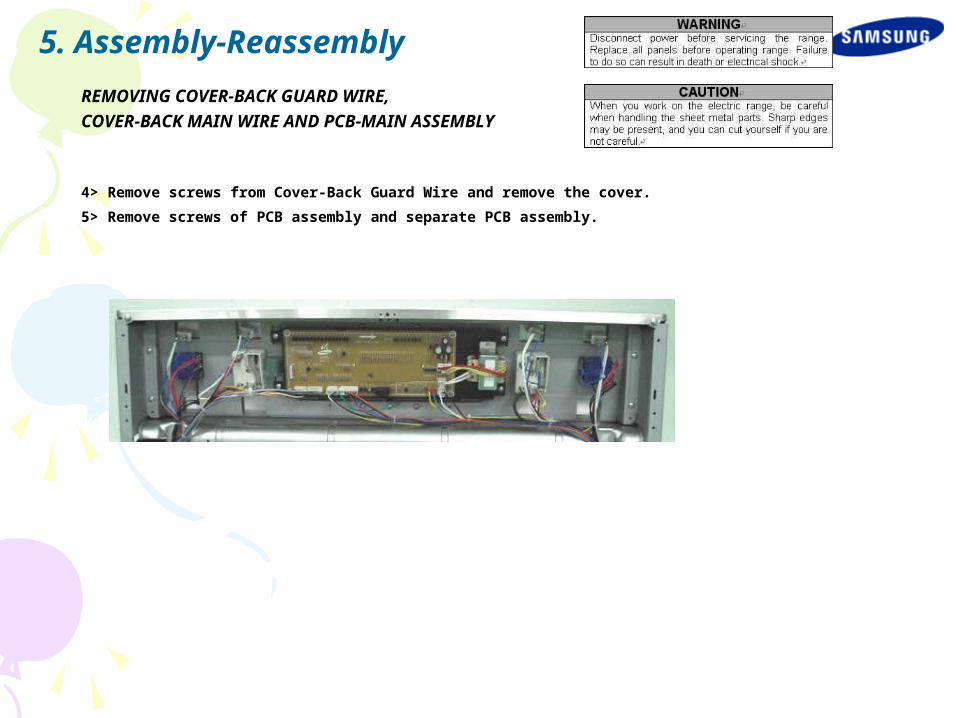
4> Remove screws from Cover-Back Guard Wire and remove the cover.
5> Remove screws of PCB assembly and separate PCB assembly.
5. Assembly-Reassembly

REMOVING COVER-BACK GUARD WIRE,
COVER-BACK MAIN WIRE AND PCB-MAIN ASSEMBLY
1> Turn off the electrical supply going to the range.
2>Pull the range away from the wall so that you can access the rear panel.
3> Remove Cover-Back Main Wire and Cover-Back Guard Wire (See step 3~4 on page 3-2)
4>There are 2 PCB's (power control board). When you check PCB, check the proper PCB in default mode and check main PCB.
5> To remove the control power supply: a) Disconnect 2 connectors. b) Remove the two screws
5. Assembly-Reassembly
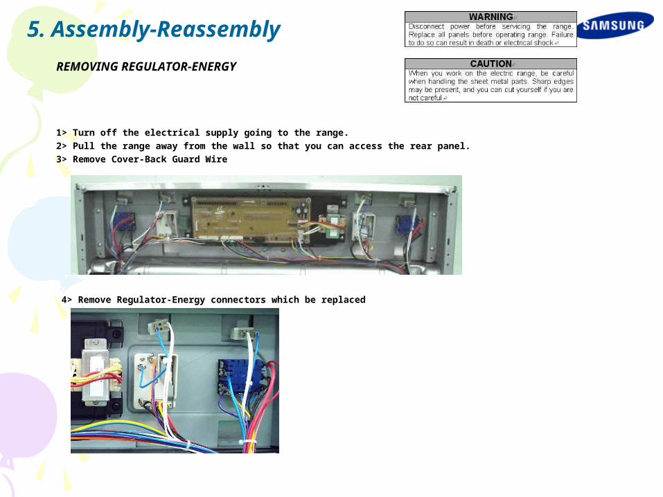
REMOVING REGULATOR-ENERGY
1> Turn off the electrical supply going to the range.
2> Pull the range away from the wall so that you can access the rear panel.
3> Remove Cover-Back Guard Wire
4> Remove Regulator-Energy connectors which be replaced
5. Assembly-Reassembly

REMOVING REGULATOR-ENERGY
4> Pull out the Knob-Dial.
5> Remove 2 screws and replace Regulator-Energy .
5. Assembly-Reassembly
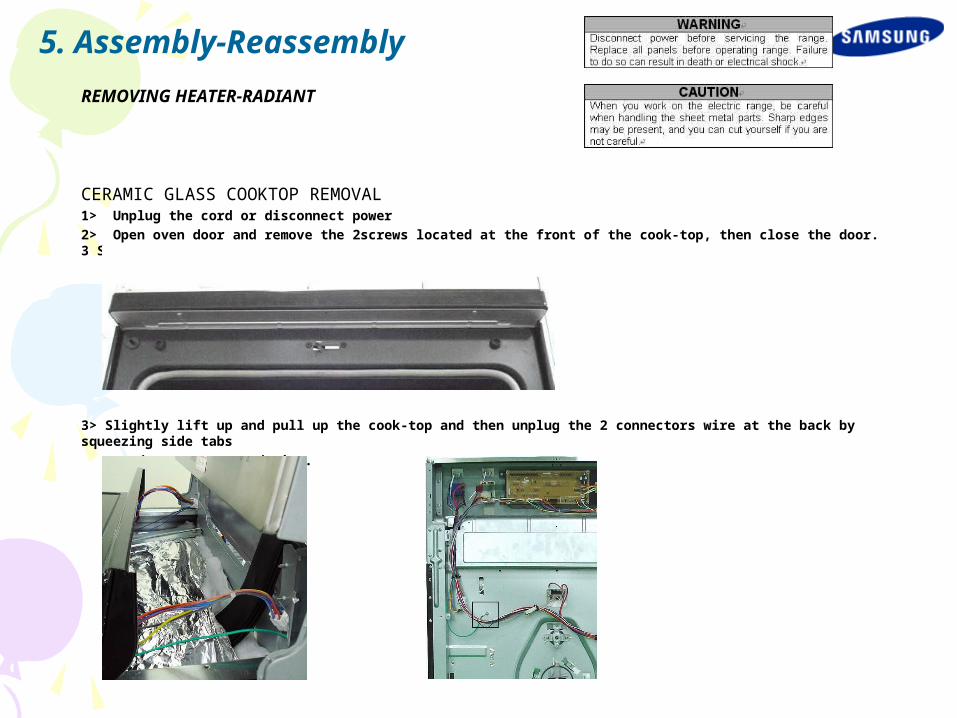
REMOVING HEATER-RADIANT
CERAMIC GLASS COOKTOP REMOVAL 1> Unplug the cord or disconnect power
2> Open oven door and remove the 2screws located at the front of the cook-top, then close the door. 3 Screws
3> Slightly lift up and pull up the cook-top and then unplug the 2 connectors wire at the back by squeezing side tabs
and unscrew ground wire.
5. Assembly-Reassembly
REMOVING HEATER-RADIANT
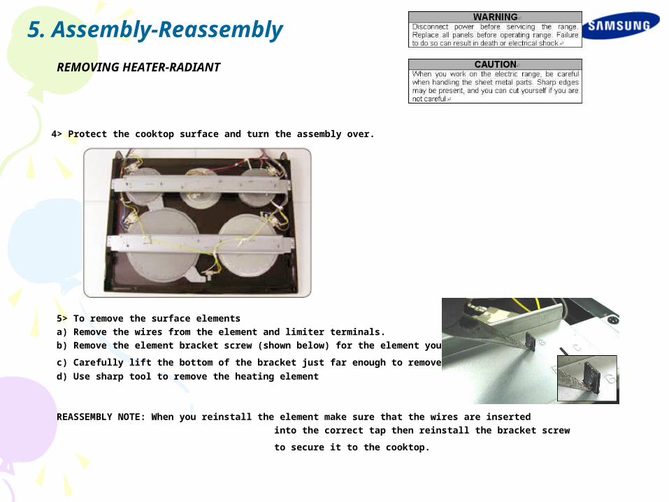
4> Protect the cooktop surface and turn the assembly over.
5> To remove the surface elements
a) Remove the wires from the element and limiter terminals.
b) Remove the element bracket screw (shown below) for the element you are servicing.
c) Carefully lift the bottom of the bracket just far enough to remove the element. d) Use sharp tool to remove the heating element
REASSEMBLY NOTE: When you reinstall the element make sure that the wires are inserted
into the correct tap then reinstall the bracket screw
to secure it to the cooktop.
5. Assembly-Reassembly
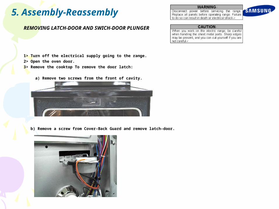
REMOVING LATCH-DOOR AND SWICH-DOOR PLUNGER
1> Turn off the electrical supply going to the range.
2> Open the oven door.
3> Remove the cooktop To remove the door latch:
a) Remove two screws from the front of cavity.
b) Remove a screw from Cover-Back Guard and remove latch-door.
5. Assembly-Reassembly
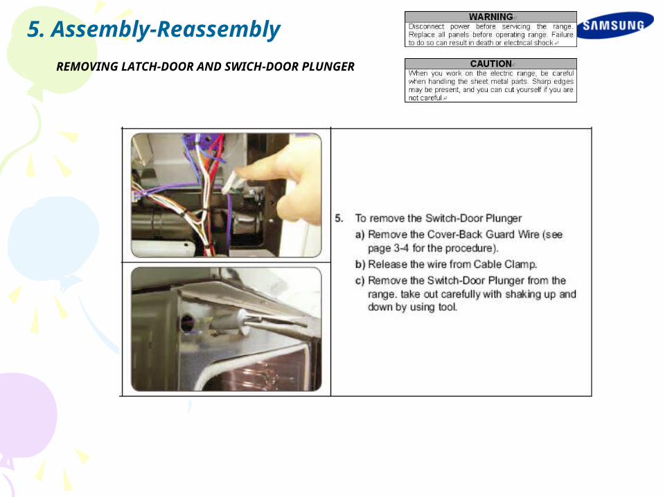
REMOVING LATCH-DOOR AND SWICH-DOOR PLUNGER
5. Assembly-Reassembly

REMOVING HEATER-BROIL
5. Assembly-Reassembly
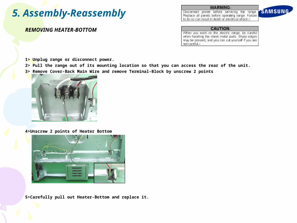
REMOVING HEATER-BOTTOM
1> Unplug range or disconnect power.
2> Pull the range out of its mounting location so that you can access the rear of the unit.
3> Remove Cover-Back Main Wire and remove Terminal-Block by unscrew 2 points
4>Unscrew 2 points of Heater Bottom
5>Carefully pull out Heater-Bottom and replace it.
5. Assembly-Reassembly
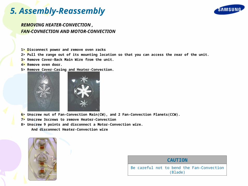
REMOVING HEATER-CONVECTION ,
FAN-COVNECTION AND MOTOR-CONVECTION
1> Disconnect power and remove oven racks
2> Pull the range out of its mounting location so that you can access the rear of the unit.
3> Remove Cover-Back Main Wire from the unit.
4> Remove oven door.
5> Remove Cover-Casing and Heater-Convection.
6> Unscrew nut of Fan-Convection Main(CW), and 2 Fan-Convection Planets(CCW).
7> Unscrew 3screws to remove Heater-Convection
8> Unscrew 9 points and disconnect a Motor-Convection wire.
And disconnect Heater-Convection wire
CAUTION
Be careful not to bend the Fan-Convection(Blade)
5. Assembly-Reassembly

REMOVING LAMP
To replace bulb and bulb cover:
1> Disconnect power.
2> Remove oven door.
3> Turn the glass bulb cover in the back of the oven counterclockwise to remove.
4> Turn bulb counterclockwise to remove from socket.
5> Replace bulb and bulb cover by turning clockwise.
To replace socket assembly:
6> Disconnect the wires from the socket terminals.
7> Use a screwdriver and bend the clips on the socket away from the edges of the liner hole(there are 6 clips on th e socket),
and pull the socket out of the liner. Push the socket out from the back of the unit.
CAUTION
Be careful not to scratch or chip the oven linerpaint when you remove the oven light socket inthe next step.
5. Assembly-Reassembly
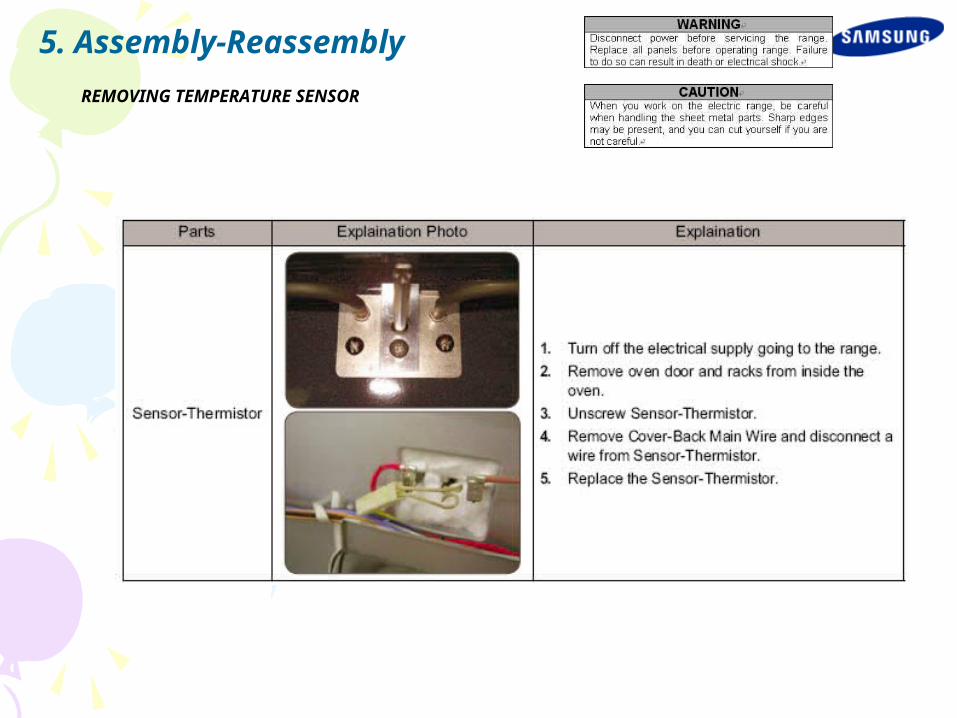
REMOVING TEMPERATURE SENSOR
5. Assembly-Reassembly
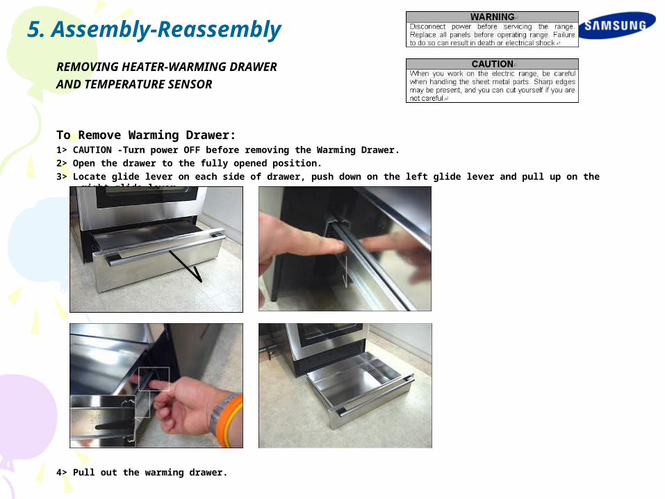
REMOVING HEATER-WARMING DRAWER
AND TEMPERATURE SENSOR
To Remove Warming Drawer: 1> CAUTION -Turn power OFF before removing the Warming Drawer.
2> Open the drawer to the fully opened position.
3> Locate glide lever on each side of drawer, push down on the left glide lever and pull up on the right glide lever.
4> Pull out the warming drawer.
5. Assembly-Reassembly
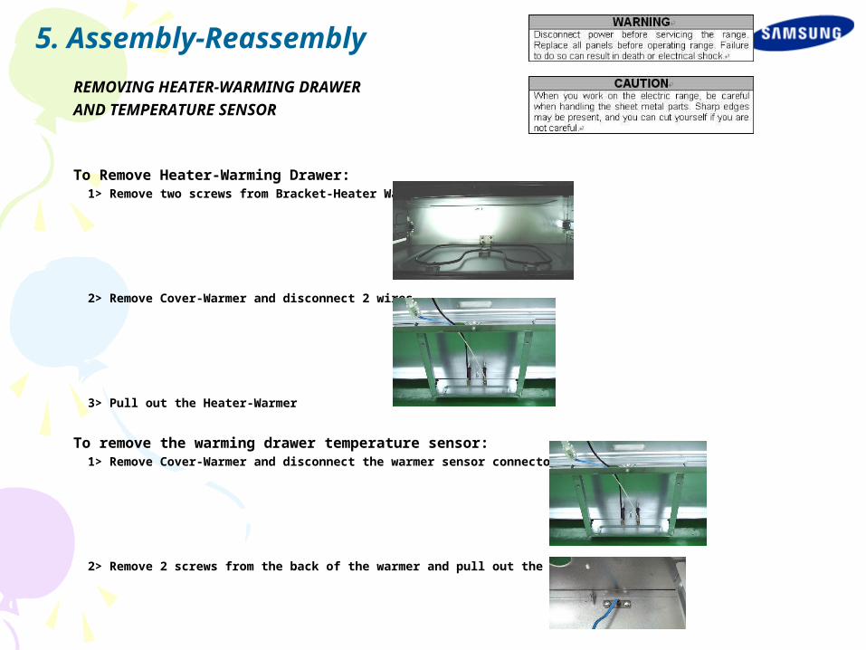
REMOVING HEATER-WARMING DRAWER
AND TEMPERATURE SENSOR
To Remove Heater-Warming Drawer: 1> Remove two screws from Bracket-Heater Warmer.
2> Remove Cover-Warmer and disconnect 2 wires.
3> Pull out the Heater-Warmer
To remove the warming drawer temperature sensor:
1> Remove Cover-Warmer and disconnect the warmer sensor connector.
2> Remove 2 screws from the back of the warmer and pull out the warmer sensor.
5. Assembly-Reassembly
REMOVING AND REPLACING OVEN DOOR
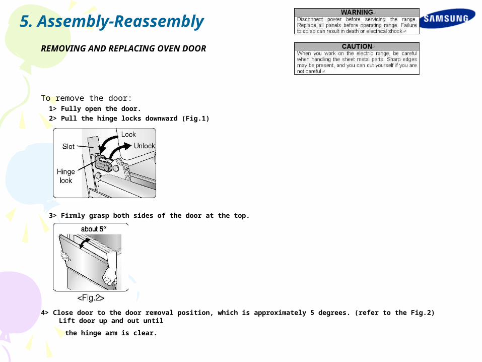
To remove the door: 1> Fully open the door.
2> Pull the hinge locks downward (Fig.1)
3> Firmly grasp both sides of the door at the top.
4> Close door to the door removal position, which is approximately 5 degrees. (refer to the Fig.2) Lift door up and out until
the hinge arm is clear.
5. Assembly-Reassembly
REMOVING AND REPLACING OVEN DOOR
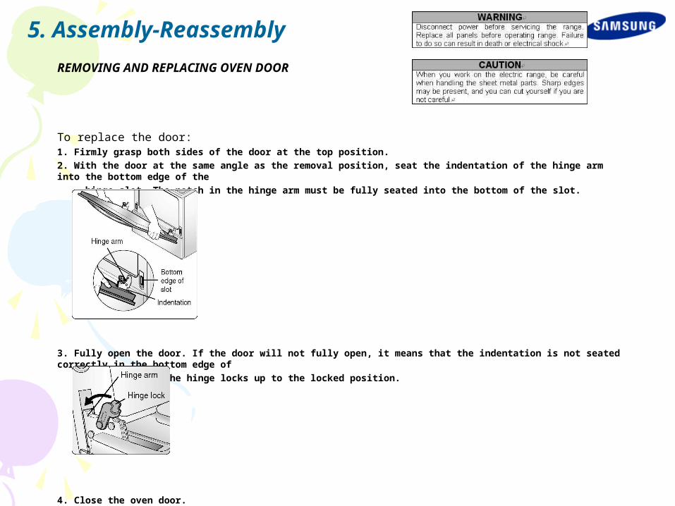
To replace the door: 1. Firmly grasp both sides of the door at the top position.
2. With the door at the same angle as the removal position, seat the indentation of the hinge arm into the bottom edge of the
hinge slot. The notch in the hinge arm must be fully seated into the bottom of the slot.
3. Fully open the door. If the door will not fully open, it means that the indentation is not seated correctly in the bottom edge of
the slot. Push the hinge locks up to the locked position.
4. Close the oven door.
5. Assembly-Reassembly
REMOVING HANDLE-DOOR
AND GLASS-INNER
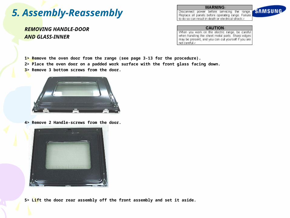
1> Remove the oven door from the range (see page 3-13 for the procedure).
2> Place the oven door on a padded work surface with the front glass facing down.
3> Remove 3 bottom screws from the door.
4> Remove 2 Handle-screws from the door.
5> Lift the door rear assembly off the front assembly and set it aside.
5. Assembly-Reassembly
REMOVING HANDLE-DOOR
AND GLASS-INNER
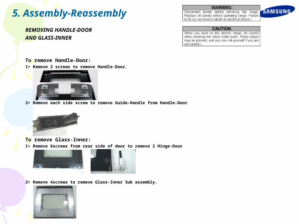
To remove Handle-Door: 1> Remove 2 screws to remove Handle-Door.
2> Remove each side screw to remove Guide-Handle from Handle-Door
To remove Glass-Inner: 1> Remove 6screws from rear side of door to remove 2 Hinge-Door
2> Remove 4screws to remove Glass-Inner Sub assembly.
5. Assembly-Reassembly

REMOVING HANDLE-DOOR
AND GLASS-INNER
3> Remove 7screws to remove Baffle-Door.
4> Remove Baffle-Door and take out the Glass-Inner assembly.
5> Unfold 2 flanges of Cover-Frame Inner Glass to taking out Glass-Inner.
5. Assembly-Reassembly
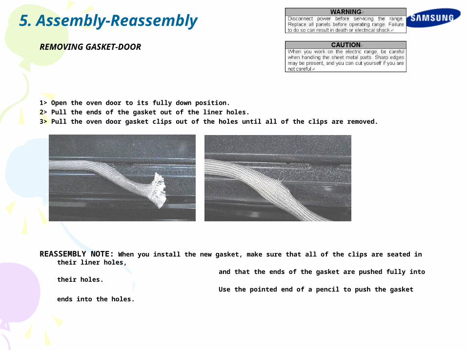
REMOVING GASKET-DOOR
1> Open the oven door to its fully down position.
2> Pull the ends of the gasket out of the liner holes.
3> Pull the oven door gasket clips out of the holes until all of the clips are removed.
REASSEMBLY NOTE: When you install the new gasket, make sure that all of the clips are seated in their liner holes,
and that the ends of the gasket are pushed fully into their holes.
Use the pointed end of a pencil to push the gasket ends into the holes.
5. Assembly-Reassembly
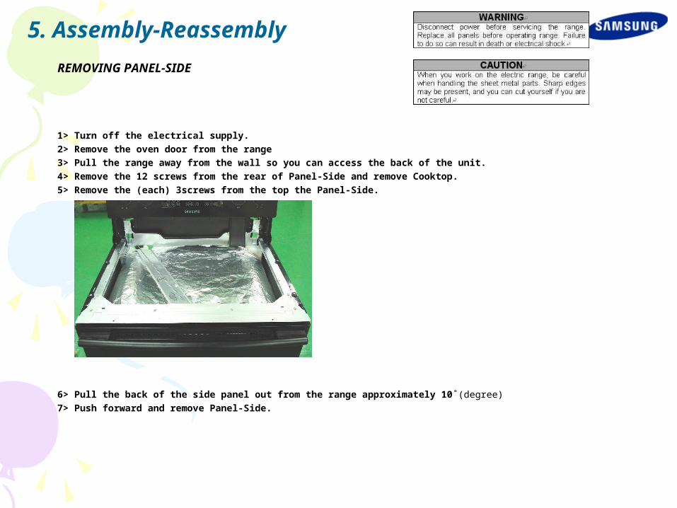
REMOVING PANEL-SIDE
1> Turn off the electrical supply.
2> Remove the oven door from the range
3> Pull the range away from the wall so you can access the back of the unit.
4> Remove the 12 screws from the rear of Panel-Side and remove Cooktop.
5> Remove the (each) 3screws from the top the Panel-Side.
6> Pull the back of the side panel out from the range approximately 10˚(degree)
7> Push forward and remove Panel-Side.
5. Assembly-Reassembly
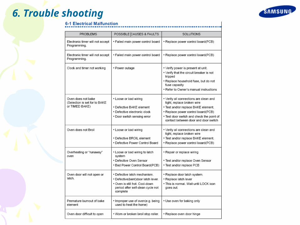
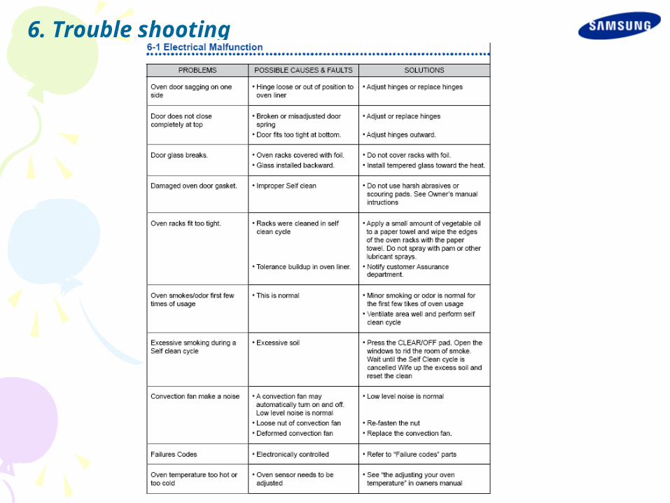
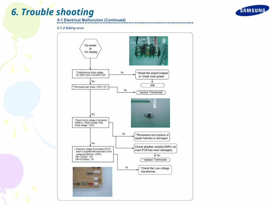
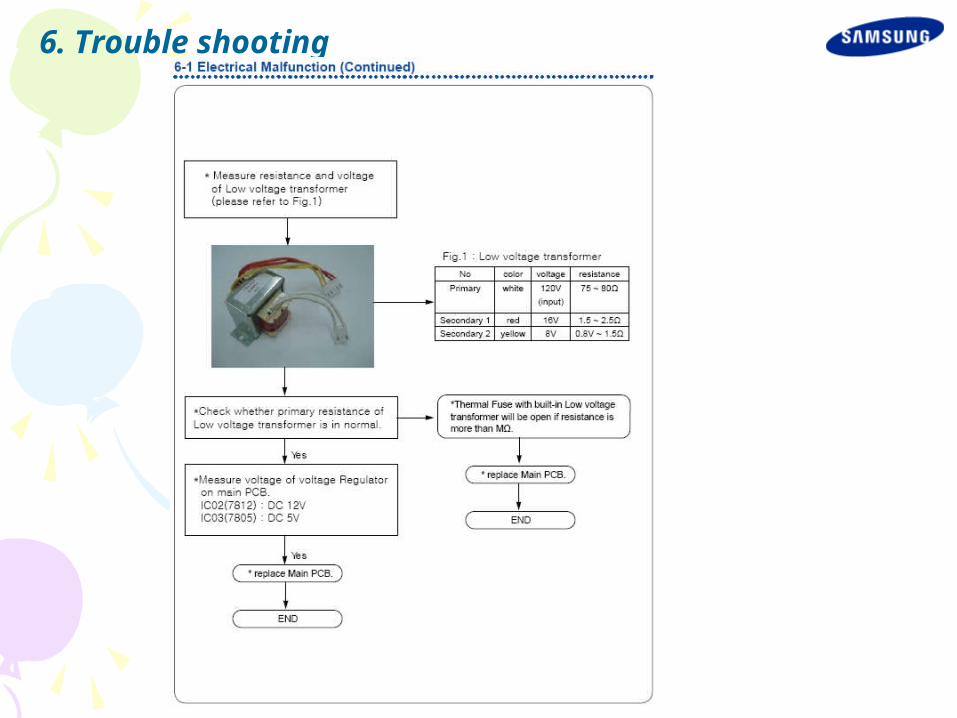
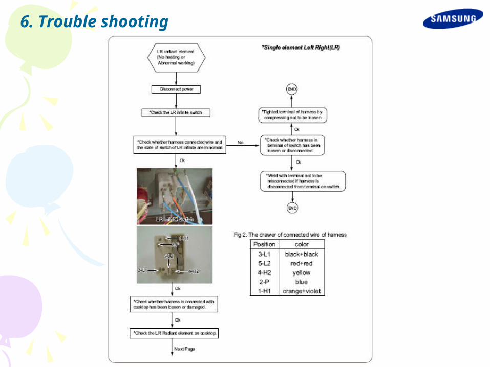
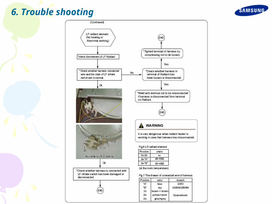
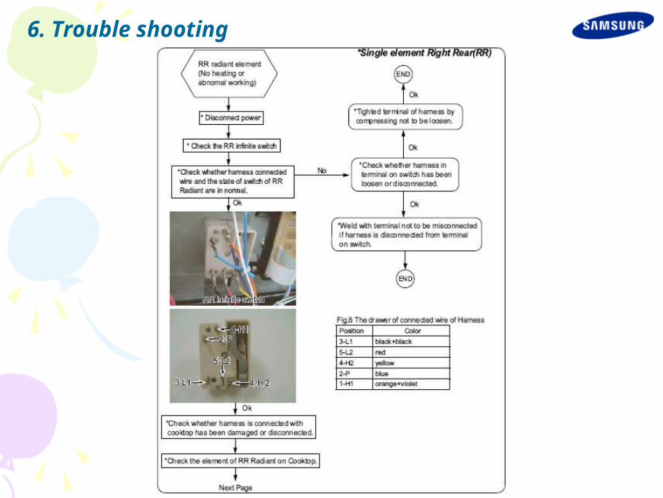
6. Trouble shooting
6. Trouble shooting
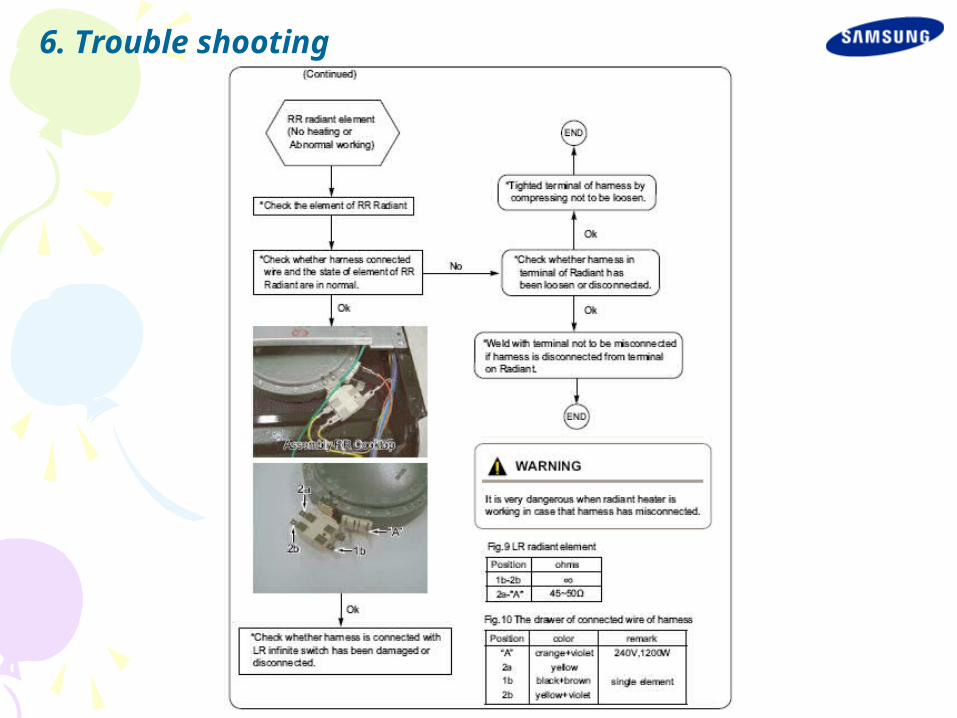
6. Trouble shooting
6. Trouble shooting
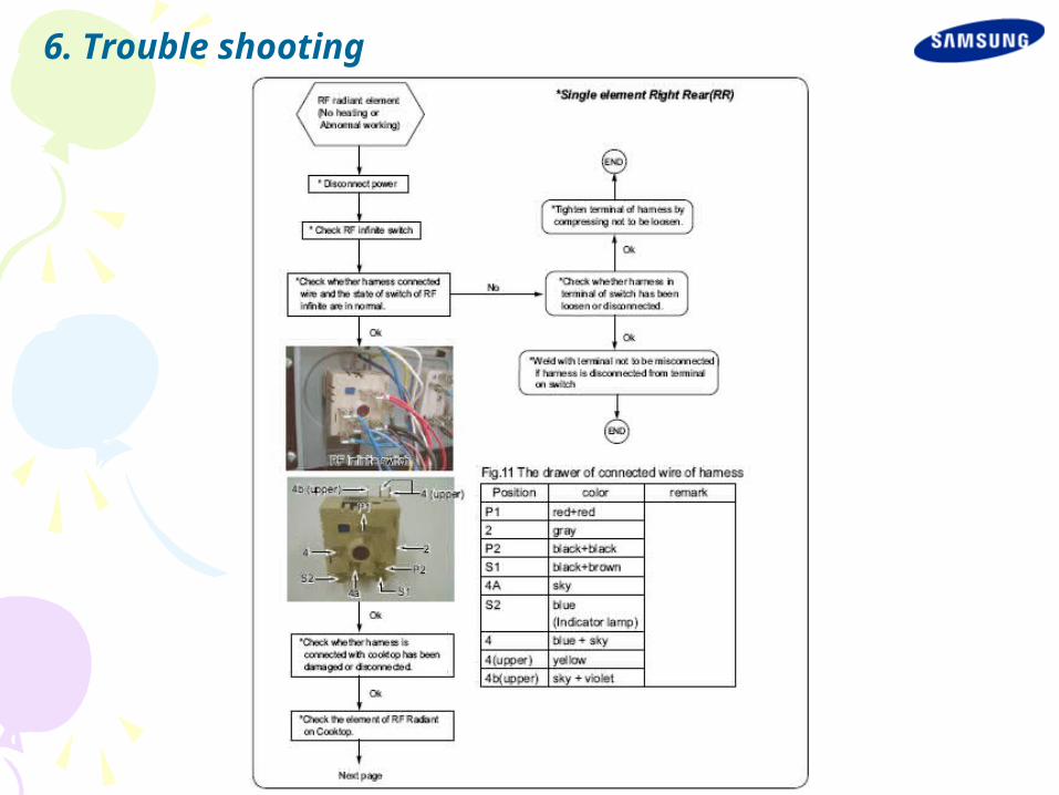
6. Trouble shooting

6. Trouble shooting

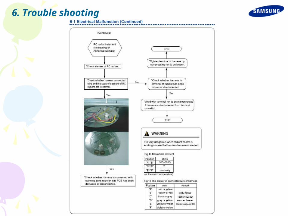
6. Trouble shooting
6. Trouble shooting
6. Trouble shooting
6. Trouble shooting
6. Trouble shooting

6. Trouble shooting

6. Trouble shooting
6. Trouble shooting
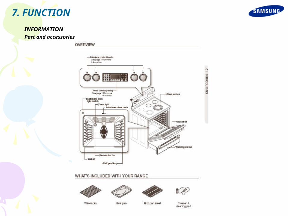
7. FUNCTION
INFORMATIONPart and accessories
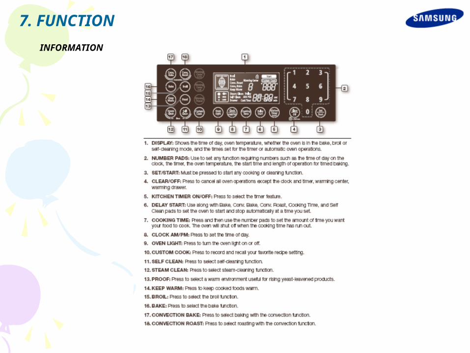
INFORMATION
7. FUNCTION
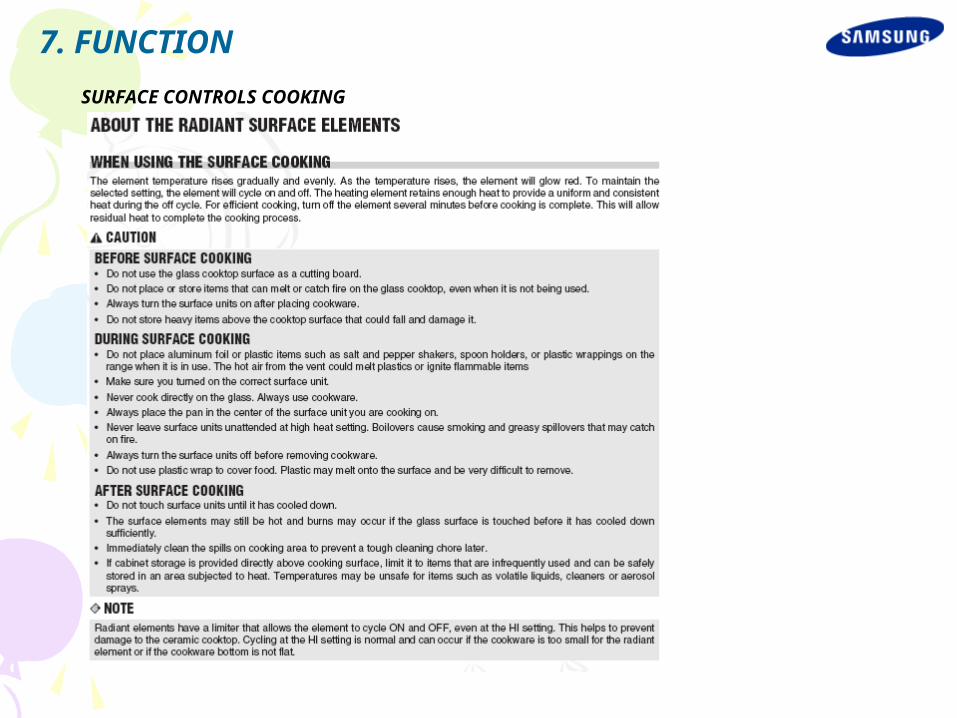
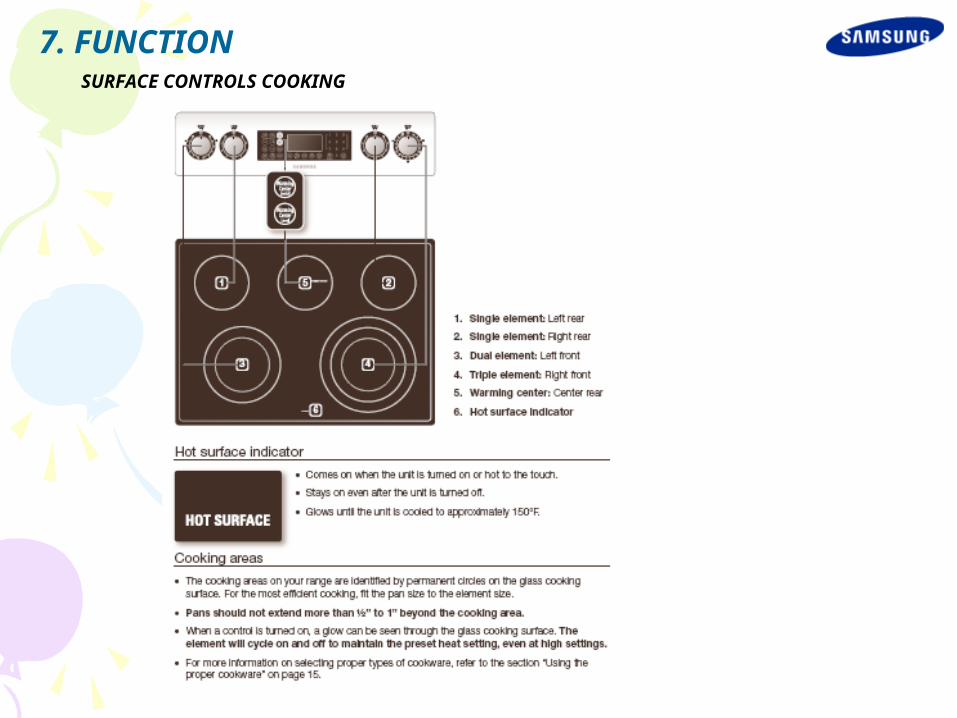
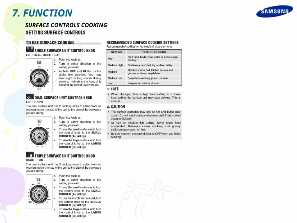
SURFACE CONTROLS COOKING
7. FUNCTION
SURFACE CONTROLS COOKING
7. FUNCTION
SURFACE CONTROLS COOKING
7. FUNCTION

SURFACE CONTROLS COOKING
7. FUNCTION

SURFACE CONTROLS COOKING
7. FUNCTION
SURFACE CONTROLS COOKING
7. FUNCTION
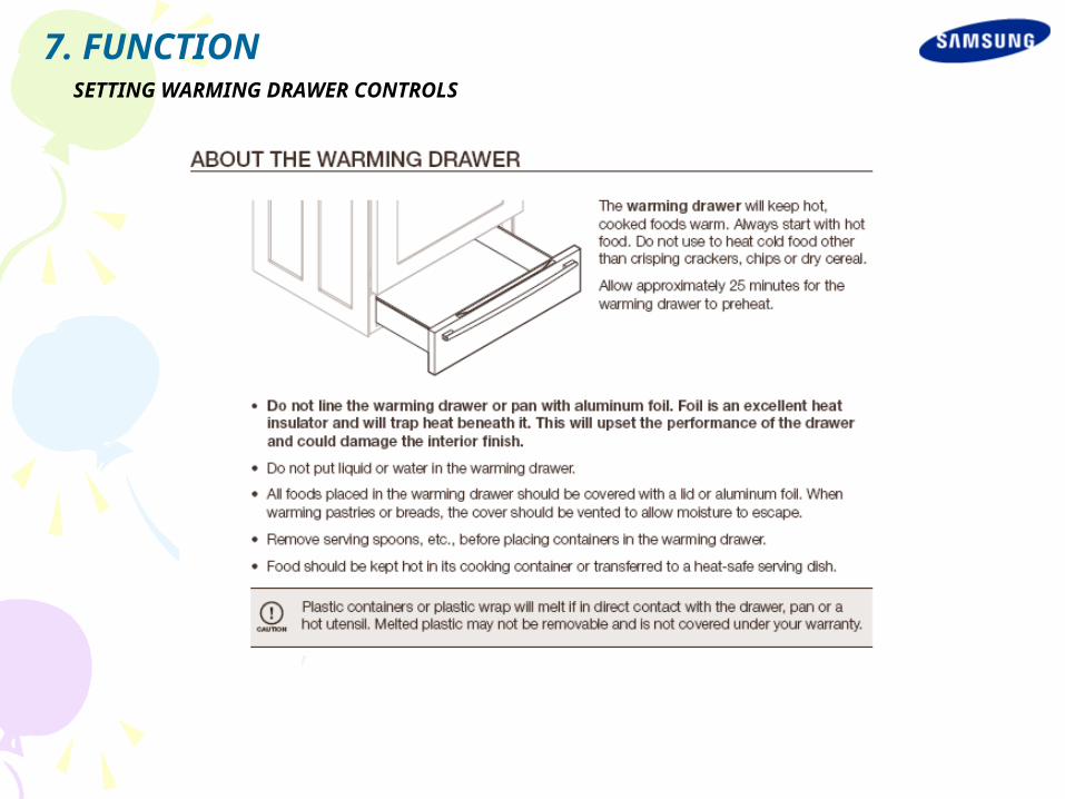
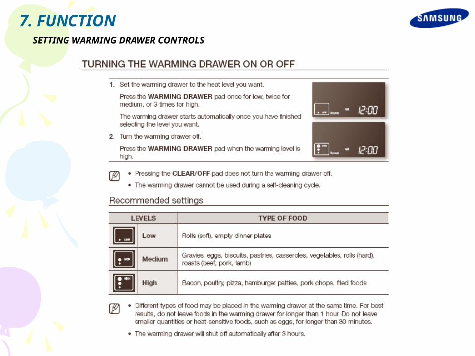
SETTING WARMING DRAWER CONTROLS
7. FUNCTION
SETTING WARMING DRAWER CONTROLS
7. FUNCTION
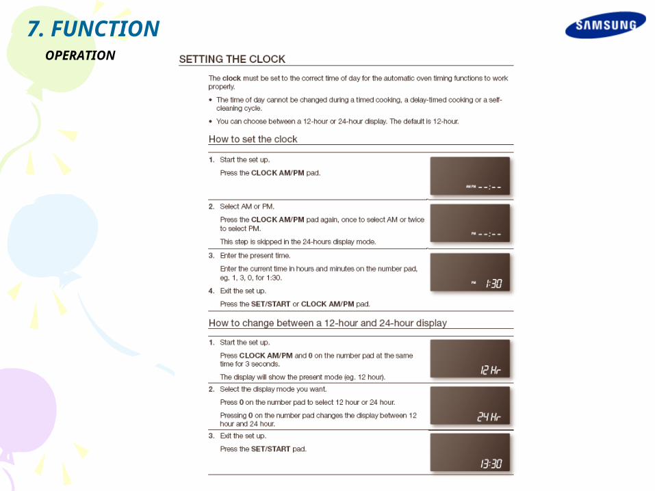
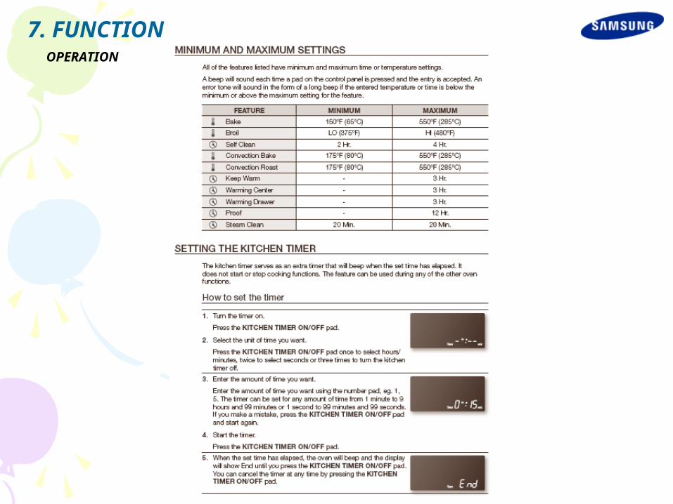
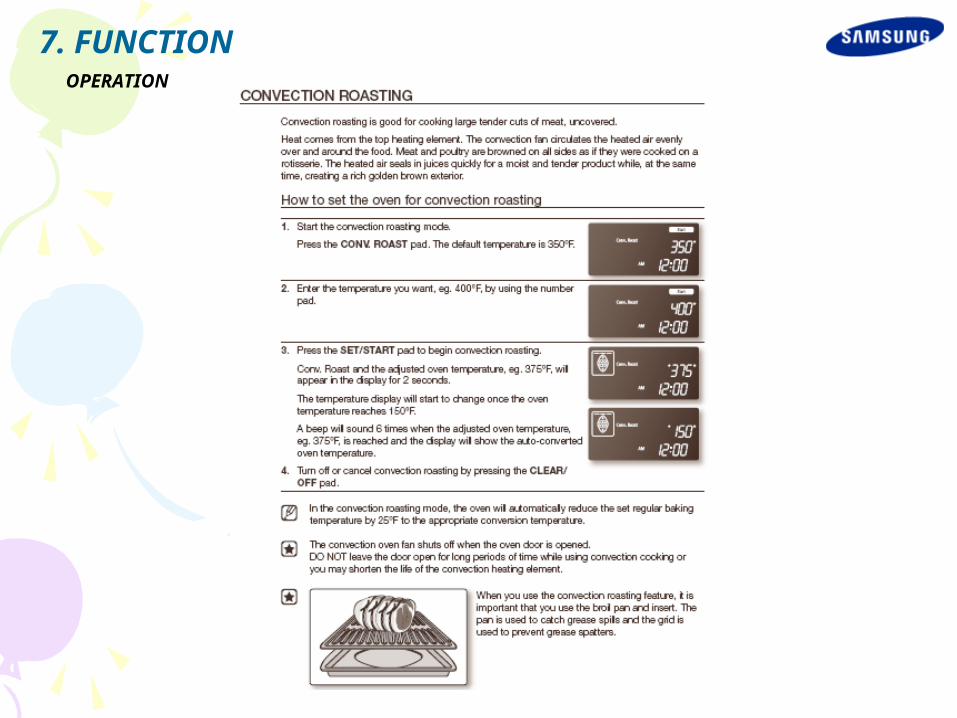
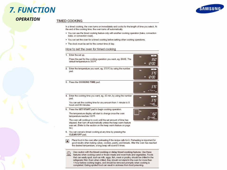
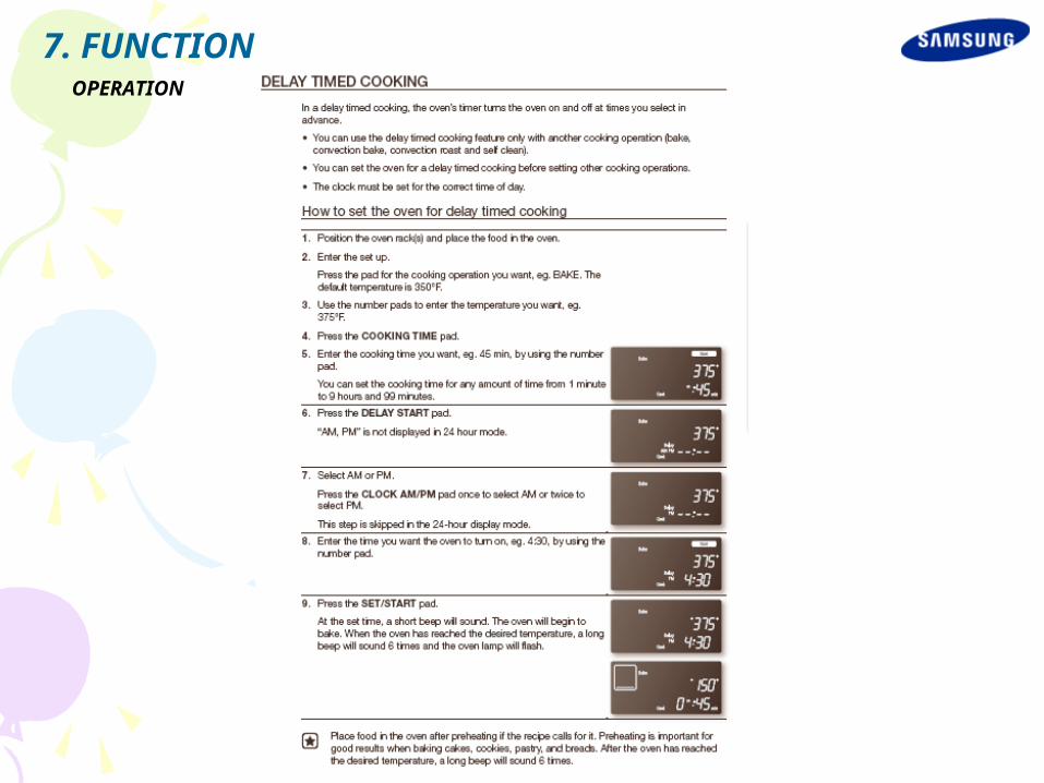
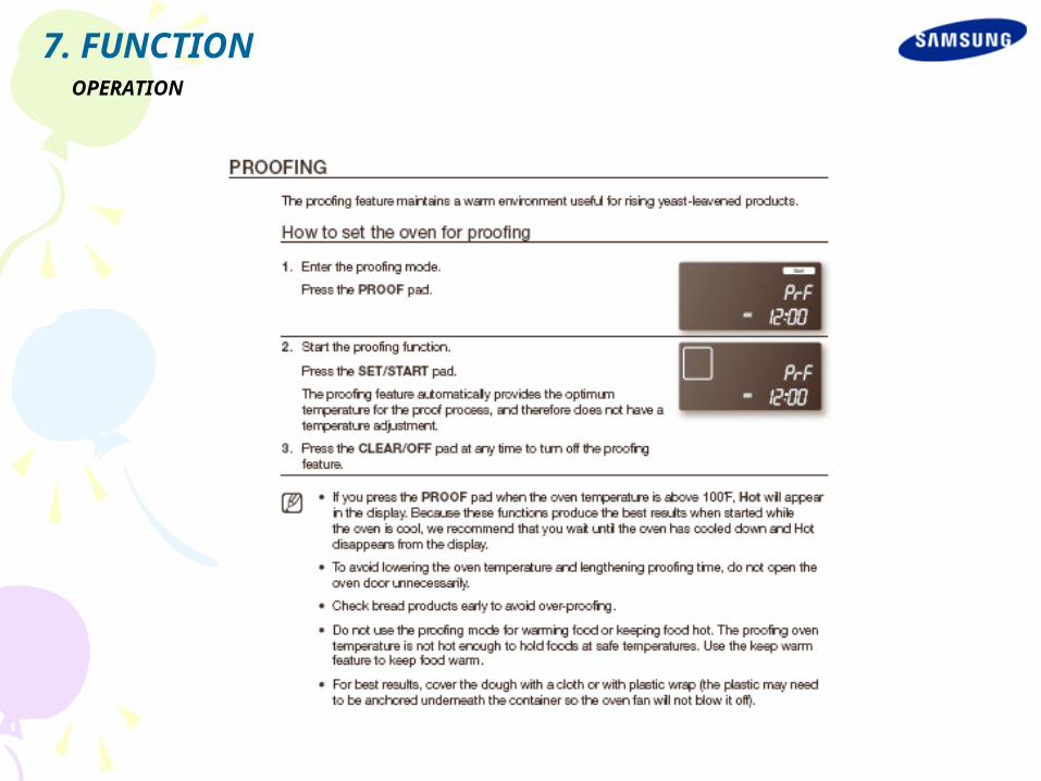
OPERATION
7. FUNCTION
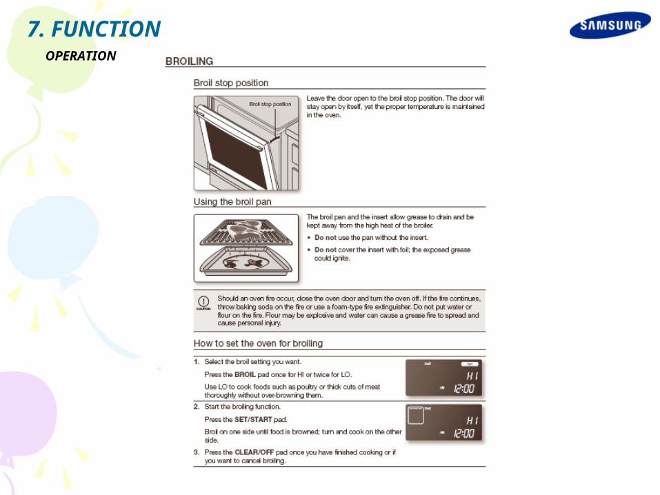
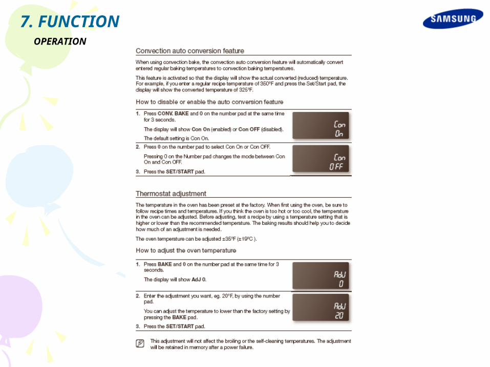
OPERATION
7. FUNCTION

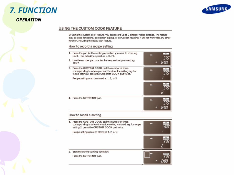
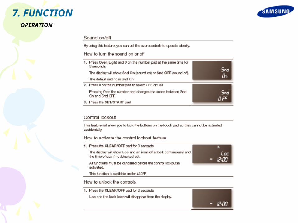
OPERATION
7. FUNCTION

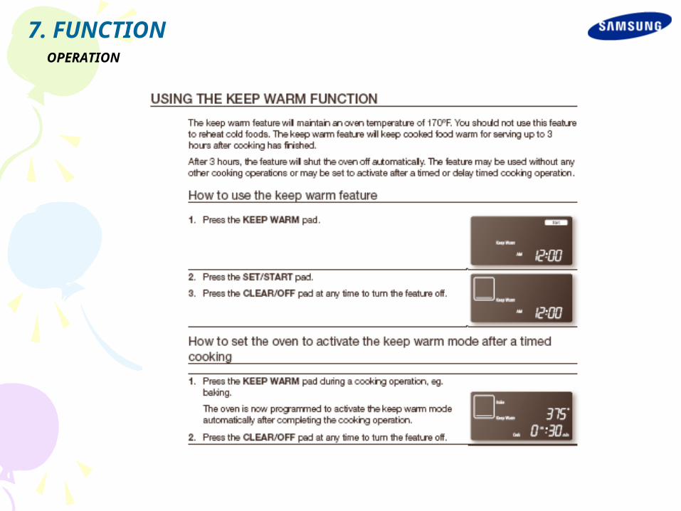
OPERATION
7. FUNCTION

OPERATION
7. FUNCTION
OPERATION
7. FUNCTION
OPERATION
7. FUNCTION
OPERATION
7. FUNCTION
OPERATION
7. FUNCTION

OPERATION
7. FUNCTION
OPERATION
7. FUNCTION
OPERATION
7. FUNCTION
OPERATION
7. FUNCTION

OPERATION
7. FUNCTION
OPERATION
7. FUNCTION
OPERATION
7. FUNCTION
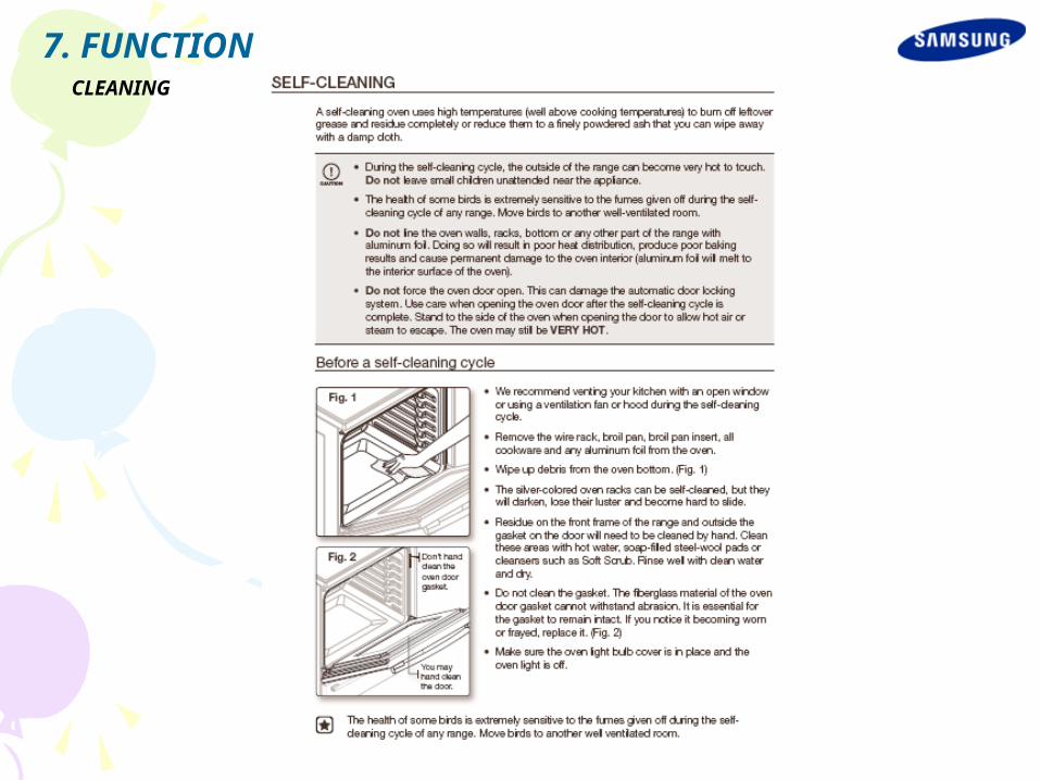
CLEANING
7. FUNCTION
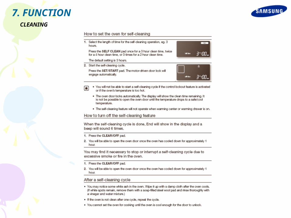
CLEANING
7. FUNCTION

CLEANING
7. FUNCTION
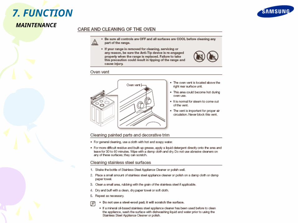
MAINTENANCE
7. FUNCTION
MAINTENANCE
7. FUNCTION
MAINTENANCE
7. FUNCTION
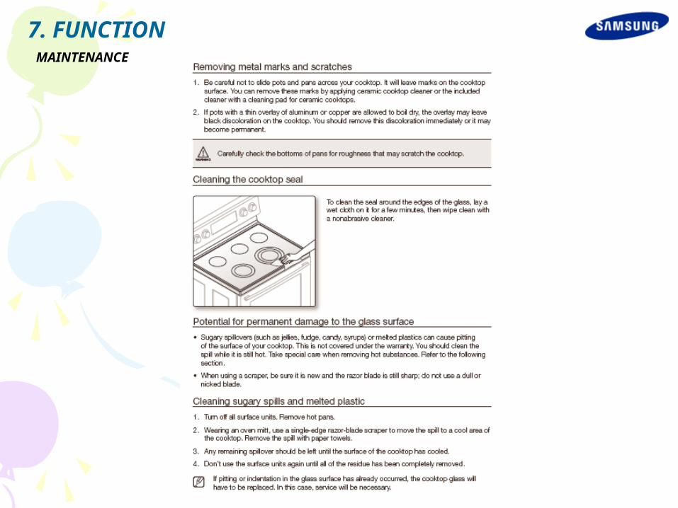
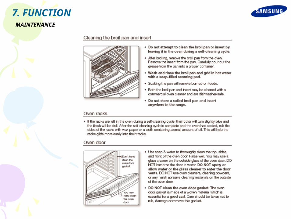
MAINTENANCE
7. FUNCTION

MAINTENANCE
7. FUNCTION

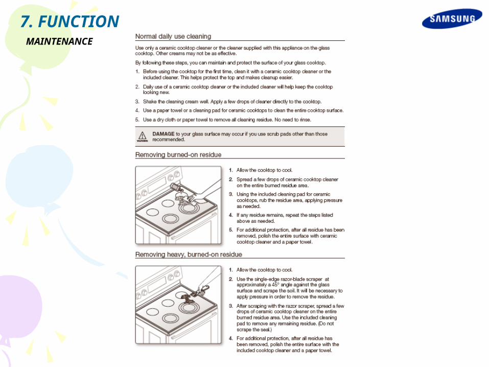
MAINTENANCE
7. FUNCTION
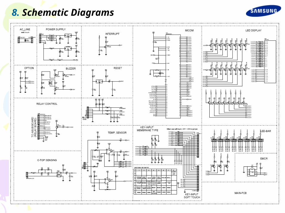
8. Schematic Diagrams

8. Schematic Diagrams
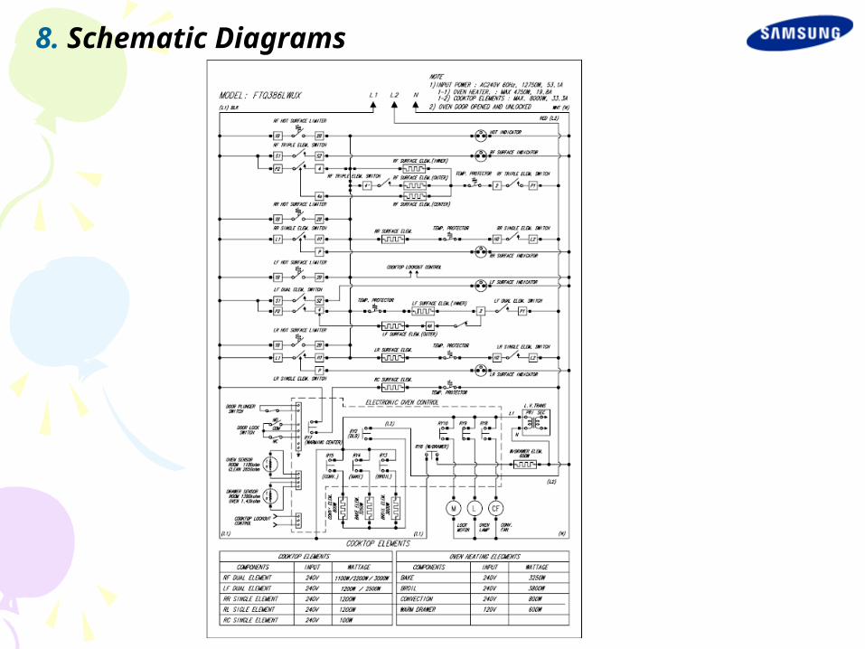
8. Schematic Diagrams