30 Amp Power PCB Relay PTRH-T - Picker Relay · T2 (1A), T3 (1C) PC Pins & QC Pins T4 (1A), T5 (1C)...
4
409 International Parkway, #200 Richardson, TX 75081 www.PickerCom ponents.com Sales: (972) 713-6272 (888) 997-3933 e-mail: [email protected] Dimensions are listed for reference purposes only. Specifications and Availability subject to change without notice. PTRH-T Rev N 5/14/2020 1 of 4 30 Amp Power PCB Relay PTRH-T CONTACT DATA Material AgCdO, AgSnO2I n2O3, AgCdO+Au Initial Contact Resistance 50 mΩ Max. @ 1 A, 6 VDC Maximum Switching Voltage 110 VDC, 300 VAC Maximum Switching Current 30 A Maximum Switching Power 900 W, 7,500 VA Service Life Mechanical 1 X 10 7 Operations Electrical 5 X 10 4 Operations E93379 Load Type Voltage 1 Form A (SPST-NO) 1 Form B (SPDT-NC) 1 Form C NO NC General Purpose 240 VAC* 30 A* 20 A* 30 A* 20 A* 30 VDC 30 A 20 A 30 A 20 A Resistive (100.000 Cycles) 120 VAC 30 A 20 A 30 A 20 A 250 VAC 30 A 20 A 30 A 20 A Motor (30,000 Cycles) 240 VAC 2 HP —— 2 HP —— 120 VAC 1 HP —— 1 HP —— LRA/FLA 240 VAC 80 A/30 A —— 80 A/30 —— 120 VAC 96 A/30 A —— 96 A/30 —— CHARACTERISTICS Operate Time Less than 15 ms Release Time Less than 10 ms Insulation Resistance 1,000 MΩ min, at 500 VDC, 50% RH Dielectric Strength 50 Hz 2,500 V 1 Min Between Coil and Contacts 4,000 V without Pin 6 50 Hz 1,500 V 1 min. Between Contacts Power Consumption 0.9 W, 0.6 W Shock Resistance 200 m/s, 11 ms Vibration Resistance 10 - 55 Hz Double Amplitude Meets UL 508 and UL 873 Spacing - 3.18 mm Through Air, 6.36 mm Over Surface. FEATURES Popular Power PCB Relay Footprint - T91 30 Amp 250 VAC General Purpose UL Rating Two Versions: T2 (1A), T3 (1C) PC Pins & QC Pins T4 (1A), T5 (1C) QC Pins with Mounting Tabs UL Class F Insulation Optional IP67 Epoxy Sealed Version Available Meets UL 508 and UL 873 Spacing RoHS Compliant T2/T3 T4/T5 *UL Approval ORDERING INFORMATION Example: PTRH -1C -12 S F T -T5 -X 67 Model: PTRH (PTRH-T) Contact Form: 1A, 1B, 1C Coil Voltage: 3, 5, 6, 9, 12, 15, 24, 48, 110 Enclosure: T2 & T3: C: Dust Cover; S: Sealed; T4 & T5: S: Covered, not Washable Insulation Material: Nil : Class B; F: Class F Contact Material: Nil : AgCdO; T: AgSnO2In2O3; Mounting Type: T2: 1 Form A PCB & QC; T3; 1 Form C PCB & QC; T4: 1 Form 1A Panel all QC; T5: 1 Form C Panel all QC RoHS Compliant: -X IP67 Epoxy Sealed: 67 (Water Proof) Pinout: A: Alternate Quick Connect Pinout Coil Sensitivity: Nil: 0.9 W**; 0.6: 0.6 W (**0.9 W is Industry Standard) Gold Plated Contacts: Nil: None; G: AgCdO+Au T2 & T3 Box Quantity: 600; Inner Box 300, T4 & T5 Box Quantity: 400: Inner Box:100 CHARACTERISTICS Continued Terminal Strength 10N Solderability 260 ºC for 5 seconds Operating Temperature Range - 55°C to 100°C Class B Operating Temperature Range - 55°C to 125°C Class F Relative Humidity 85% (at 40°C) Weight 13.5 gr Approximately Material Compliant To EU RoHS V2. EU REACH V3 UL / CUL Ratings
Transcript of 30 Amp Power PCB Relay PTRH-T - Picker Relay · T2 (1A), T3 (1C) PC Pins & QC Pins T4 (1A), T5 (1C)...

409 International Parkway, #200 Richardson, TX 75081 www.PickerCom ponents.com
Sales: (972) 713-6272 (888) 997-3933 e-mail: [email protected]
Dimensions are listed for reference purposes only. Specifications and Availability subject to change without notice.
PTRH-T Rev N 5/14/2020 1 of 4
30 Amp Power PCB Relay PTRH-T
CONTACT DATA Material AgCdO, AgSnO2In2O3, AgCdO+Au
Initial Contact Resistance 50 mΩ Max. @ 1 A, 6 VDC
Maximum Switching Voltage 110 VDC, 300 VAC
Maximum Switching Current 30 A
Maximum Switching Power 900 W, 7,500 VA
Service Life Mechanical 1 X 10⁷ Operations
Electrical 5 X 10⁴ Operations
E93379
Load Type Voltage 1 Form A
(SPST-NO)
1 Form B (SPDT-NC)
1 Form C
NO NC
General Purpose 240 VAC* 30 A* 20 A* 30 A* 20 A*
30 VDC 30 A 20 A 30 A 20 A
Resistive (100.000 Cycles)
120 VAC 30 A 20 A 30 A 20 A
250 VAC 30 A 20 A 30 A 20 A
Motor (30,000 Cycles)
240 VAC 2 HP —— 2 HP —— 120 VAC 1 HP —— 1 HP ——
LRA/FLA 240 VAC 80 A/30 A —— 80 A/30 —— 120 VAC 96 A/30 A —— 96 A/30 ——
CHARACTERISTICS Operate Time Less than 15 ms
Release Time Less than 10 ms
Insulation Resistance 1,000 MΩ min, at 500 VDC, 50% RH
Dielectric Strength 50 Hz 2,500 V 1 Min Between Coil and Contacts 4,000 V without Pin 6
50 Hz 1,500 V 1 min. Between Contacts
Power Consumption 0.9 W, 0.6 W
Shock Resistance 200 m/s, 11 ms
Vibration Resistance 10 - 55 Hz Double Amplitude
Meets UL 508 and UL 873 Spacing - 3.18 mm Through Air, 6.36 mm Over Surface.
FEATURES Popular Power PCB Relay Footprint - T91
30 Amp 250 VAC General Purpose UL Rating
Two Versions: T2 (1A), T3 (1C) PC Pins & QC Pins T4 (1A), T5 (1C) QC Pins with Mounting Tabs
UL Class F Insulation Optional
IP67 Epoxy Sealed Version Available
Meets UL 508 and UL 873 Spacing
RoHS Compliant
T2/T3 T4/T5
*UL Approval
ORDERING INFORMATION Example: PTRH -1C -12 S F T -T5 -X 67
Model: PTRH (PTRH-T)
Contact Form: 1A, 1B, 1C
Coil Voltage: 3, 5, 6, 9, 12, 15, 24, 48, 110
Enclosure: T2 & T3: C: Dust Cover; S: Sealed;
T4 & T5: S: Covered, not Washable
Insulation Material: Nil: Class B; F: Class F
Contact Material: Nil: AgCdO; T: AgSnO2In2O3;
Mounting Type: T2: 1 Form A PCB & QC; T3; 1 Form C PCB & QC;
T4: 1 Form 1A Panel all QC; T5: 1 Form C Panel all QC
RoHS Compliant: -X
IP67 Epoxy Sealed: 67 (Water Proof)
Pinout: A: Alternate Quick Connect Pinout
Coil Sensitivity: Nil: 0.9 W**; 0.6: 0.6 W (**0.9 W is Industry Standard)
Gold Plated Contacts: Nil: None; G: AgCdO+Au T2 & T3 Box Quantity: 600; Inner Box 300, T4 & T5 Box Quantity: 400: Inner Box:100
CHARACTERISTICS Continued
Terminal Strength 10N
Solderability 260 ºC for 5 seconds
Operating Temperature Range - 55°C to 100°C Class B
Operating Temperature Range - 55°C to 125°C Class F
Relative Humidity 85% (at 40°C)
Weight 13.5 gr Approximately
Material Compliant To EU RoHS V2. EU REACH V3
UL / CUL Ratings

409 International Parkway, #200 Richardson, TX 75081 www.PickerCom ponents.com
Sales: (972) 713-6272 (888) 997-3933 e-mail: [email protected]
Dimensions are listed for reference purposes only. Specifications and Availability subject to change without notice.
PTRH-T Rev N 5/14/2020 2 of 4
PTRH-T PTRH-T
COIL DATA
Coil Voltage Coil Power (W) Must Release Voltage Min
(VDC)
Must Operate Voltage Max
(VDC) Resistance (Ohms ± 10%)
Rated Max 0.6 W 0.9 W
3 3.9 15 10 2.25 0.3
5 6.5 42 28 3.75 0.5
6 7.8 60 40 4.50 0.6
9 11.7 135 90 6.75 0.9
12 15.6 240 150 9.00 1.2
15 19.5 375 260 10.25 1.5
18 23.4 540 380 13.50 1.8
24 31.2 960 640 18.00 2.4
28 36.4 1307 871 21.0 2.8
48 62.4 3840 2560 36.00 4.8
110 143 20167 13445 82.50 11.0
NOTES: The use of any coil voltage less than the rated voltage will compromise the operation of the relays. Must Operate Voltage an d Must Release Voltages are for test purposes only and are not to be used as design criteria.
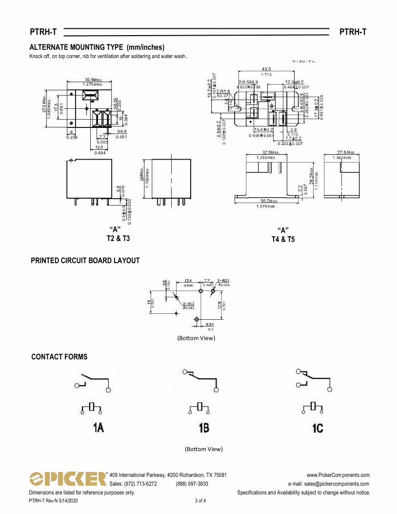
MOUNTING TYPE (mm/inches) Knock off, on top corner, nib for ventilation after soldering and water wash.
“T2” & “T3” “T4” & “T5”
Note:
Power Pins are 0.8 mm x 1.5 mm
Coil Pins are O0.8 mm
3-
*0.9 W is Industry Standard
409 International Parkway, #200 Richardson, TX 75081 www.PickerCom ponents.com
Sales: (972) 713-6272 (888) 997-3933 e-mail: [email protected]
Dimensions are listed for reference purposes only. Specifications and Availability subject to change without notice.
PTRH-T Rev N 5/14/2020 3 of 4
PTRH-T PTRH-T
ALTERNATE MOUNTING TYPE (mm/inches)
(Bottom View)
(Bottom View)
CONTACT FORMS
PRINTED CIRCUIT BOARD LAYOUT
“A” T2 & T3
“A” T4 & T5
Knock off, on top corner, nib for ventilation after soldering and water wash.

409 International Parkway, #200 Richardson, TX 75081 www.PickerCom ponents.com
Sales: (972) 713-6272 (888) 997-3933 e-mail: [email protected]
Dimensions are listed for reference purposes only. Specifications and Availability subject to change without notice.
PTRH-T Rev N 5/14/2020 4 of 4