30-0300 X-Series UEGO Gauge · 3 2/11/2016 - DOCU MENT NUMBER: 10-0300 ©2016A EP e rf oma ncl t i...
13
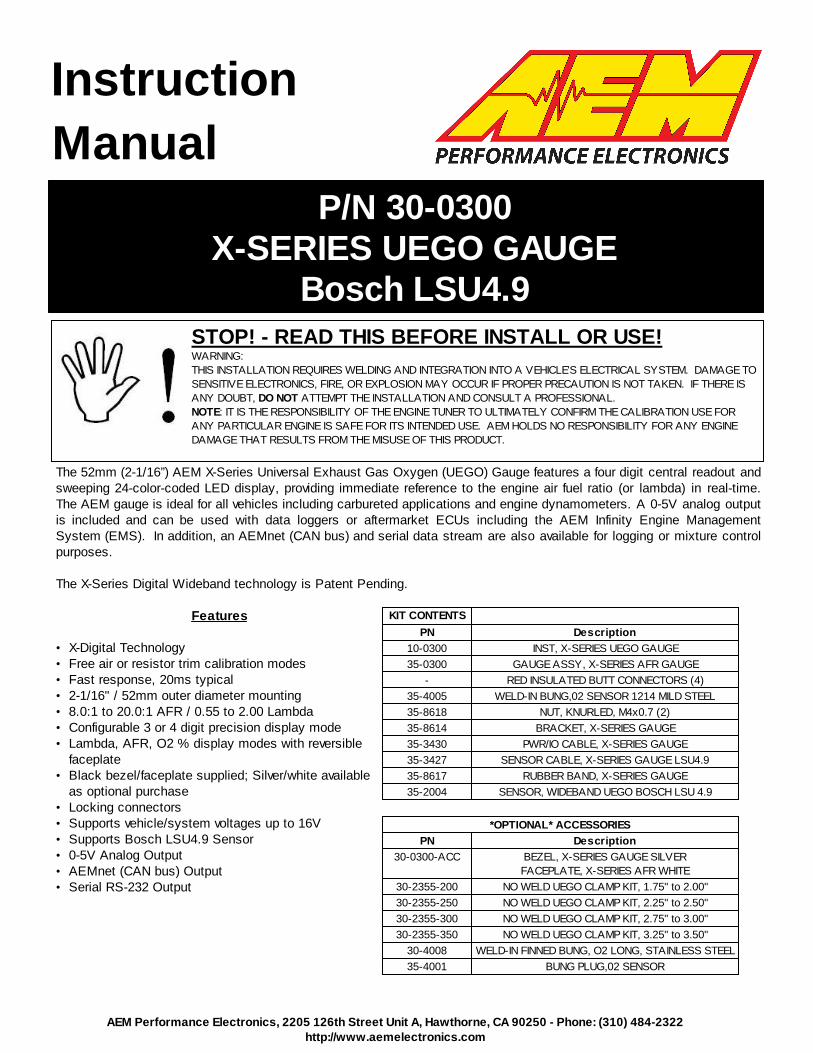
P/N 30-0300 X-SERIES UEGO GAUGE Bosch LSU4.9 AEM Performance Electronics, 2205 126th Street Unit A, Hawthorne, CA 90250 - Phone: (310) 484-2322 http://www.aemelectronics.com STOP! - READ THIS BEFORE INSTALL OR USE! WARNING: THIS INSTALLATION REQUIRES WELDING AND INTEGRATION INTO A VEHICLE'S ELECTRICAL SYSTEM. DAMAGE TO SENSITIVE ELECTRONICS, FIRE, OR EXPLOSION MAY OCCUR IF PROPER PRECAUTION IS NOT TAKEN. IF THERE IS ANY DOUBT, DO NOT ATTEMPT THE INSTALLATION AND CONSULT A PROFESSIONAL. NOTE : IT IS THE RESPONSIBILITY OF THE ENGINE TUNER TO ULTIMATELY CONFIRM THE CALIBRATION USE FOR ANY PARTICULAR ENGINE IS SAFE FOR ITS INTENDED USE. AEM HOLDS NO RESPONSIBILITY FOR ANY ENGINE DAMAGE THAT RESULTS FROM THE MISUSE OF THIS PRODUCT. Instruction Manual The 52mm (2-1/16”) AEM X-Series Universal Exhaust Gas Oxygen (UEGO) Gauge features a four digit central readout and sweeping 24-color-coded LED display, providing immediate reference to the engine air fuel ratio (or lambda) in real-time. The AEM gauge is ideal for all vehicles including carbureted applications and engine dynamometers. A 0-5V analog output is included and can be used with data loggers or aftermarket ECUs including the AEM Infinity Engine Management System (EMS). In addition, an AEMnet (CAN bus) and serial data stream are also available for logging or mixture control purposes. The X-Series Digital Wideband technology is Patent Pending. Features • X-Digital Technology • Free air or resistor trim calibration modes • Fast response, 20ms typical • 2-1/16" / 52mm outer diameter mounting • 8.0:1 to 20.0:1 AFR / 0.55 to 2.00 Lambda • Configurable 3 or 4 digit precision display mode • Lambda, AFR, O2 % display modes with reversible faceplate • Black bezel/faceplate supplied; Silver/white available as optional purchase • Locking connectors • Supports vehicle/system voltages up to 16V • Supports Bosch LSU4.9 Sensor • 0-5V Analog Output • AEMnet (CAN bus) Output • Serial RS-232 Output KIT CONTENTS PN Description 10-0300 INST, X-SERIES UEGO GAUGE 35-0300 GAUGE ASSY, X-SERIES AFR GAUGE - RED INSULATED BUTT CONNECTORS (4) 35-4005 WELD-IN BUNG,02 SENSOR 1214 MILD STEEL 35-8618 NUT, KNURLED, M4x0.7 (2) 35-8614 BRACKET, X-SERIES GAUGE 35-3430 PWR/IO CABLE, X-SERIES GAUGE 35-3427 SENSOR CABLE, X-SERIES GAUGE LSU4.9 35-8617 RUBBER BAND, X-SERIES GAUGE 35-2004 SENSOR, WIDEBAND UEGO BOSCH LSU 4.9 *OPTIONAL* ACCESSORIES PN Description 30-0300-ACC BEZEL, X-SERIES GAUGE SILVER FACEPLATE, X-SERIES AFR WHITE 30-2355-200 NO WELD UEGO CLAMP KIT, 1.75" to 2.00" 30-2355-250 NO WELD UEGO CLAMP KIT, 2.25" to 2.50" 30-2355-300 NO WELD UEGO CLAMP KIT, 2.75" to 3.00" 30-2355-350 NO WELD UEGO CLAMP KIT, 3.25" to 3.50" 30-4008 WELD-IN FINNED BUNG, O2 LONG, STAINLESS STEEL 35-4001 BUNG PLUG,02 SENSOR
Transcript of 30-0300 X-Series UEGO Gauge · 3 2/11/2016 - DOCU MENT NUMBER: 10-0300 ©2016A EP e rf oma ncl t i...
P/N 30-0300X-SERIES UEGO GAUGE
Bosch LSU4.9
AEM Performance Electronics, 2205 126th Street Unit A, Hawthorne, CA 90250 - Phone: (310) 484-2322http://www.aemelectronics.com
STOP! - READ THIS BEFORE INSTALL OR USE!WARNING:
THIS INSTALLATION REQUIRES WELDING AND INTEGRATION INTO A VEHICLE'S ELECTRICAL SYSTEM. DAMAGE TO
SENSITIVE ELECTRONICS, FIRE, OR EXPLOSION MAY OCCUR IF PROPER PRECAUTION IS NOT TAKEN. IF THERE IS
ANY DOUBT, DO NOT ATTEMPT THE INSTALLATION AND CONSULT A PROFESSIONAL.
NOTE: IT IS THE RESPONSIBILITY OF THE ENGINE TUNER TO ULTIMATELY CONFIRM THE CALIBRATION USE FOR
ANY PARTICULAR ENGINE IS SAFE FOR ITS INTENDED USE. AEM HOLDS NO RESPONSIBILITY FOR ANY ENGINE
DAMAGE THAT RESULTS FROM THE MISUSE OF THIS PRODUCT.
Instruction
Manual
The 52mm (2-1/16”) AEM X-Series Universal Exhaust Gas Oxygen (UEGO) Gauge features a four digit central readout andsweeping 24-color-coded LED display, providing immediate reference to the engine air fuel ratio (or lambda) in real-time.The AEM gauge is ideal for all vehicles including carbureted applications and engine dynamometers. A 0-5V analog outputis included and can be used with data loggers or aftermarket ECUs including the AEM Infinity Engine ManagementSystem (EMS). In addition, an AEMnet (CAN bus) and serial data stream are also available for logging or mixture controlpurposes.
The X-Series Digital Wideband technology is Patent Pending.
Features
· X-Digital Technology· Free air or resistor trim calibration modes· Fast response, 20ms typical· 2-1/16" / 52mm outer diameter mounting· 8.0:1 to 20.0:1 AFR / 0.55 to 2.00 Lambda· Configurable 3 or 4 digit precision display mode· Lambda, AFR, O2 % display modes with reversible
faceplate· Black bezel/faceplate supplied; Silver/white available
as optional purchase· Locking connectors· Supports vehicle/system voltages up to 16V· Supports Bosch LSU4.9 Sensor· 0-5V Analog Output· AEMnet (CAN bus) Output· Serial RS-232 Output
KIT CONTENTS
PN Description
10-0300 INST, X-SERIES UEGO GAUGE
35-0300 GAUGE ASSY, X-SERIES AFR GAUGE
- RED INSULATED BUTT CONNECTORS (4)
35-4005 WELD-IN BUNG,02 SENSOR 1214 MILD STEEL
35-8618 NUT, KNURLED, M4x0.7 (2)
35-8614 BRACKET, X-SERIES GAUGE
35-3430 PWR/IO CABLE, X-SERIES GAUGE
35-3427 SENSOR CABLE, X-SERIES GAUGE LSU4.9
35-8617 RUBBER BAND, X-SERIES GAUGE
35-2004 SENSOR, WIDEBAND UEGO BOSCH LSU 4.9
*OPTIONAL* ACCESSORIES
PN Description
30-0300-ACC BEZEL, X-SERIES GAUGE SILVER
FACEPLATE, X-SERIES AFR WHITE
30-2355-200 NO WELD UEGO CLAMP KIT, 1.75" to 2.00"
30-2355-250 NO WELD UEGO CLAMP KIT, 2.25" to 2.50"
30-2355-300 NO WELD UEGO CLAMP KIT, 2.75" to 3.00"
30-2355-350 NO WELD UEGO CLAMP KIT, 3.25" to 3.50"
30-4008 WELD-IN FINNED BUNG, O2 LONG, STAINLESS STEEL
35-4001 BUNG PLUG,02 SENSOR

2
2/11/2016 - DOCUMENT NUMBER: 10-0300 © 2016 AEM Performance Electronics
30-0300 X-Series UEGO Gauge
Wiring Installation Diagram
3
2/11/2016 - DOCUMENT NUMBER: 10-0300 © 2016 AEM Performance Electronics
30-0300 X-Series UEGO Gauge
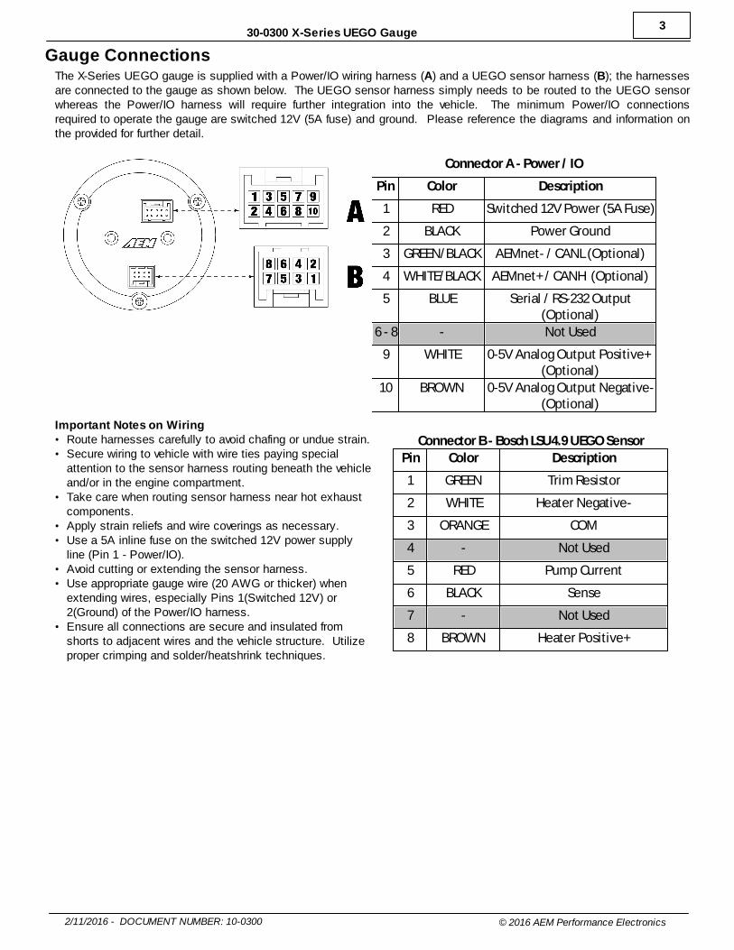
Gauge ConnectionsThe X-Series UEGO gauge is supplied with a Power/IO wiring harness (A) and a UEGO sensor harness (B); the harnessesare connected to the gauge as shown below. The UEGO sensor harness simply needs to be routed to the UEGO sensorwhereas the Power/IO harness will require further integration into the vehicle. The minimum Power/IO connectionsrequired to operate the gauge are switched 12V (5A fuse) and ground. Please reference the diagrams and information onthe provided for further detail.
Connector A - Power / IO
Pin Color Description
1 RED Switched 12V Power (5A Fuse)
2 BLACK Power Ground
3 GREEN/BLACK AEMnet- / CANL (Optional)
4 WHITE/BLACK AEMnet+ / CANH (Optional)
5 BLUE Serial / RS-232 Output(Optional)
6 - 8 - Not Used
9 WHITE 0-5V Analog Output Positive+ (Optional)
10 BROWN 0-5V Analog Output Negative-(Optional)
Important Notes on Wiring· Route harnesses carefully to avoid chafing or undue strain.· Secure wiring to vehicle with wire ties paying special
attention to the sensor harness routing beneath the vehicleand/or in the engine compartment.
· Take care when routing sensor harness near hot exhaustcomponents.
· Apply strain reliefs and wire coverings as necessary.· Use a 5A inline fuse on the switched 12V power supply
line (Pin 1 - Power/IO).· Avoid cutting or extending the sensor harness.· Use appropriate gauge wire (20 AWG or thicker) when
extending wires, especially Pins 1(Switched 12V) or2(Ground) of the Power/IO harness.
· Ensure all connections are secure and insulated fromshorts to adjacent wires and the vehicle structure. Utilizeproper crimping and solder/heatshrink techniques.
Connector B - Bosch LSU4.9 UEGO Sensor
Pin Color Description
1 GREEN Trim Resistor
2 WHITE Heater Negative-
3 ORANGE COM
4 - Not Used
5 RED Pump Current
6 BLACK Sense
7 - Not Used
8 BROWN Heater Positive+
4
2/11/2016 - DOCUMENT NUMBER: 10-0300 © 2016 AEM Performance Electronics
30-0300 X-Series UEGO Gauge
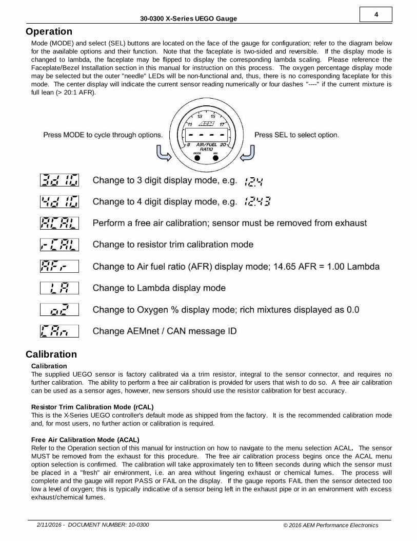
OperationMode (MODE) and select (SEL) buttons are located on the face of the gauge for configuration; refer to the diagram belowfor the available options and their function. Note that the faceplate is two-sided and reversible. If the display mode ischanged to lambda, the faceplate may be flipped to display the corresponding lambda scaling. Please reference theFaceplate/Bezel Installation section in this manual for instruction on this process. The oxygen percentage display modemay be selected but the outer "needle" LEDs will be non-functional and, thus, there is no corresponding faceplate for thismode. The center display will indicate the current sensor reading numerically or four dashes "----" if the current mixture isfull lean (> 20:1 AFR).
CalibrationCalibrationThe supplied UEGO sensor is factory calibrated via a trim resistor, integral to the sensor connector, and requires nofurther calibration. The ability to perform a free air calibration is provided for users that wish to do so. A free air calibrationcan be used as a sensor ages, however, new sensors should use the resistor calibration for best accuracy.
Resistor Trim Calibration Mode (rCAL)This is the X-Series UEGO controller's default mode as shipped from the factory. It is the recommended calibration modeand, for most users, no further action or calibration is required.
Free Air Calibration Mode (ACAL)Refer to the Operation section of this manual for instruction on how to navigate to the menu selection ACAL. The sensorMUST be removed from the exhaust for this procedure. The free air calibration process begins once the ACAL menuoption selection is confirmed. The calibration will take approximately ten to fifteen seconds during which the sensor mustbe placed in a "fresh" air environment, i.e. an area without lingering exhaust or chemical fumes. The process willcomplete and the gauge will report PASS or FAIL on the display. If the gauge reports FAIL then the sensor detected toolow a level of oxygen; this is typically indicative of a sensor being left in the exhaust pipe or in an environment with excessexhaust/chemical fumes.
5
2/11/2016 - DOCUMENT NUMBER: 10-0300 © 2016 AEM Performance Electronics
30-0300 X-Series UEGO Gauge
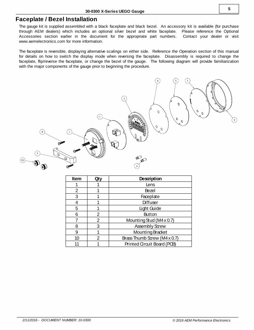
Faceplate / Bezel InstallationThe gauge kit is supplied assembled with a black faceplate and black bezel. An accessory kit is available (for purchasethrough AEM dealers) which includes an optional silver bezel and white faceplate. Please reference the OptionalAccessories section earlier in the document for the appropriate part numbers. Contact your dealer or visitwww.aemelectronics.com for more information.
The faceplate is reversible, displaying alternative scalings on either side. Reference the Operation section of this manualfor details on how to switch the display mode when reversing the faceplate. Disassembly is required to change thefaceplate, flip/reverse the faceplate, or change the bezel of the gauge. The following diagram will provide familiarizationwith the major components of the gauge prior to beginning the procedure.
Item Qty Description
1 1 Lens
2 1 Bezel
3 1 Faceplate
4 1 Diffuser
5 1 Light Guide
6 2 Button
7 2 Mounting Stud (M4 x 0.7)
8 3 Assembly Screw
9 1 Mounting Bracket
10 2 Brass Thumb Screw (M4 x 0.7)
11 1 Printed Circuit Board (PCB)

6
2/11/2016 - DOCUMENT NUMBER: 10-0300 © 2016 AEM Performance Electronics
30-0300 X-Series UEGO Gauge
Gauge Disassembly
STEP 1 - Remove the three assembly screws (8) using a #1 Phillips
head screwdriver. Separate the bezel (2) and cup (7) from the rest of the
assembly. If you have purchased the optional accessory kit, the silver
bezel may be replaced for the existing bezel at this time
STEP 2 - Separate the PCB (11) from the remaining components
STEP 3 - Slide the light guide (5) upward to remove it, the buttons may
fall out at this time - take care not to lose them
STEP 4 - As you separate the remaining components, diffuser (4),
faceplate (3), lens (1), note the order in which they were assembled.
The faceplate (3) may now be reversed to display an alternate scaling or
replaced for a different color as included in the optional accessory kit
7
2/11/2016 - DOCUMENT NUMBER: 10-0300 © 2016 AEM Performance Electronics
30-0300 X-Series UEGO Gauge
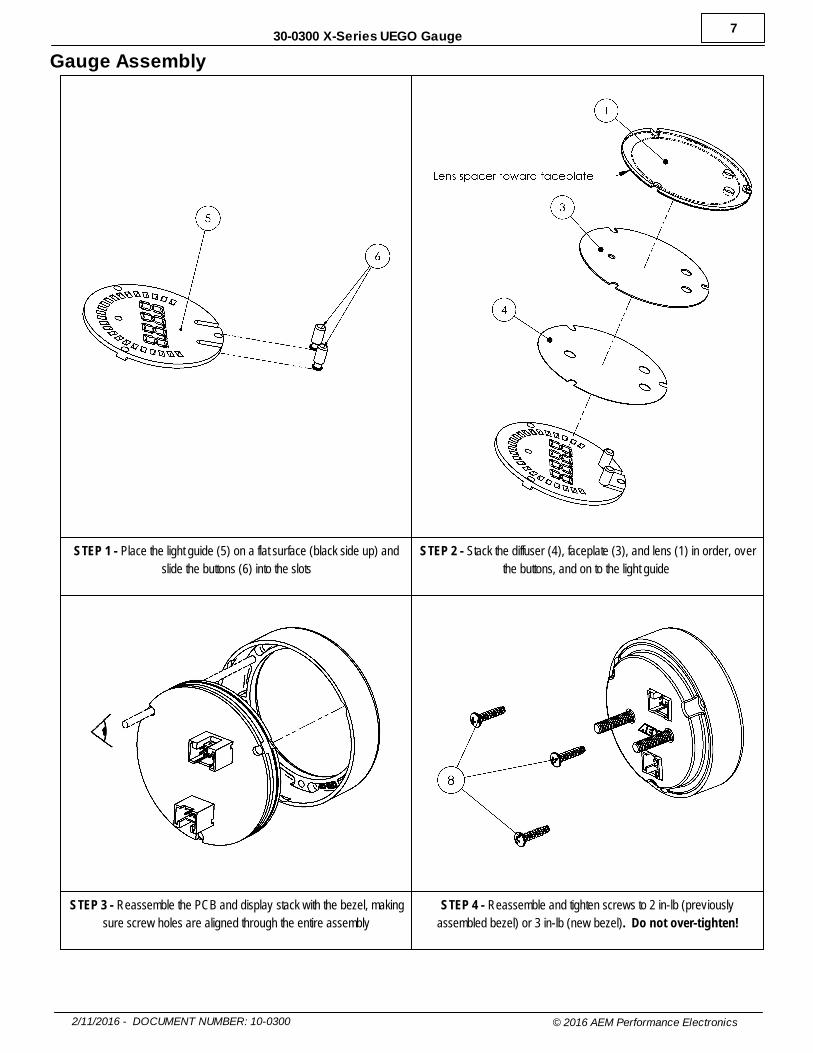
Gauge Assembly
STEP 1 - Place the light guide (5) on a flat surface (black side up) and
slide the buttons (6) into the slots
STEP 2 - Stack the diffuser (4), faceplate (3), and lens (1) in order, over
the buttons, and on to the light guide
STEP 3 - Reassemble the PCB and display stack with the bezel, making
sure screw holes are aligned through the entire assembly
STEP 4 - Reassemble and tighten screws to 2 in-lb (previously
assembled bezel) or 3 in-lb (new bezel). Do not over-tighten!

8
2/11/2016 - DOCUMENT NUMBER: 10-0300 © 2016 AEM Performance Electronics
30-0300 X-Series UEGO Gauge
What is a UEGO Wideband Sensor?A Universal Exhaust Gas Oxygen (UEGO) oxygen sensor, also known as a wideband or lambda sensor, measures theproportion of oxygen (O2) in the exhaust of a running engine. An air to fuel ratio (AFR) or lambda value can be calculatedfrom this measurement. Typically, when calibrating or "tuning" the fuel delivery system of an engine, a specific AFR canbe targeted to achieve maximum power, economy, or emissions. The output from a UEGO sensor controller can be usedto adjust a carburetor or fuel injection system to reach this target.
UEGO sensors are one of the more sophisticated sensors found in today's vehicles. The sensing element is made of azirconium dioxide ceramic with a thin platinum coating and has an integrated heating element. An electronic controller,such as is contained in AEM's X-Series UEGO Gauge or Inline Controller, is required to use a UEGO oxygen sensor. The controller connects to the sensor via multiple wires (up to 6) carrying sensitive voltages and electrical currents toprocess and calculate an AFR value. This value may be read directly from a gauge face or data-log as recorded by anECU or logger via several methods as discussed elsewhere in this manual.
Interpreting Wideband Sensor ReadingsAn internal combustion engine runs on air (which contains~20% oxygen) and fuel. The ratio of air to fuel (AFR) that,when combusted, perfectly consumes 100% of both theoxygen and fuel is called the stoichiometric ratio. This ratiois different for every fuel. Ratios lower than stoichiometrichave more fuel and are considered "rich"; ratios higher thanstoichiometric have less fuel and are considered "lean."
Fuel Stoichiometric AFR Lambda
Unleaded Gasoline 14.65 : 1 1.00
Methanol 6.47 : 1 1.00
Ethanol 9.00 : 1 1.00
Propane 15.67 : 1 1.00
CNG 17.20 : 1 1.00
Lambda is a unitless ratio that is fuel agnostic. In other words, a lambda reading of 1.0 is stochiometric for any fuel; AFR= ( Stoichiometric AFR * Lambda.)
In general, an engine will have three areas of operation: idle/cruise, wide open throttle, and fuel cut off. The exact AFRvalue that should be expected (or tuned to) for these areas is very specific to the type and configuration of each individualengine. However, while monitoring your AEM X-Series controller, you should see readings similar to the chart below. Fuelcutoff is generally experienced when completely lifting off the throttle, while decelerating in gear, at high RPM.
Operating Region WOT IDLE/CRUISE FUEL CUTOFF
Approximate AFR 10.5 (RICH) 14.7 (STOICH) 20.0 (LEAN)
IMPORTANT NOTE: Engine tuning should only be performed by experienced individuals as engine damage, or outrightfailure, can be the result of an improper calibration.
Sensor PlacementThe location at which the sensor is installed in the vehicle's exhaust system is critical to its performance and longevity. Please review the following placement guidelines:
o 18 inches (45cm) downstream of the cylinder head's exhaust port or turbocharger
o Upstream of any catalytic converters or emission control devices
o Downstream of any turbochargers or large contributors to exhaust pressure
o As far as possible from the exhaust exit (tailpipe) to avoid scavenging fresh air in low exhaust flow
conditions such as idlingo AEM's X-Series UEGO controller is a very sensitive device and, thus, it is important to have a
completely leak-free exhaust
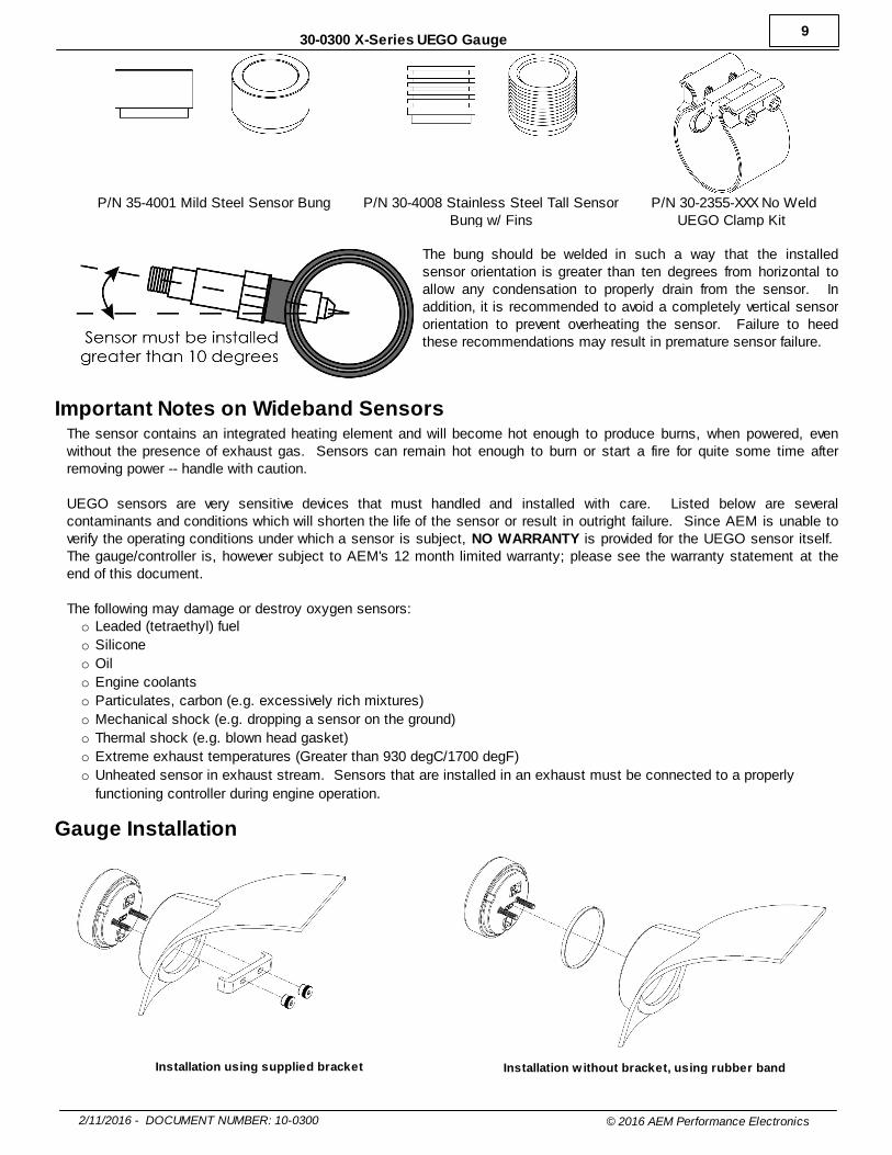
Sensor BungThe supplied mild steel sensor bung must be welded into the vehicle's exhaust. An optional stainless steel sensor bungis available for purchase from AEM dealers and may be useful in specific installation scenarios. The taller geometry ofthis bung helps bring the sensing element further out of the exhaust stream when used in small diameter tubing such asheader primaries. In addition, the finned body helps dissipate heat when used in extreme applications. As an alternativeto welding, users may purchase a P/N 30-2355-XXX No Weld UEGO Clamp Kit.
9
2/11/2016 - DOCUMENT NUMBER: 10-0300 © 2016 AEM Performance Electronics
30-0300 X-Series UEGO Gauge
P/N 35-4001 Mild Steel Sensor Bung P/N 30-4008 Stainless Steel Tall SensorBung w/ Fins
P/N 30-2355-XXX No WeldUEGO Clamp Kit
The bung should be welded in such a way that the installedsensor orientation is greater than ten degrees from horizontal toallow any condensation to properly drain from the sensor. Inaddition, it is recommended to avoid a completely vertical sensororientation to prevent overheating the sensor. Failure to heedthese recommendations may result in premature sensor failure.
Important Notes on Wideband SensorsThe sensor contains an integrated heating element and will become hot enough to produce burns, when powered, evenwithout the presence of exhaust gas. Sensors can remain hot enough to burn or start a fire for quite some time afterremoving power -- handle with caution.
UEGO sensors are very sensitive devices that must handled and installed with care. Listed below are severalcontaminants and conditions which will shorten the life of the sensor or result in outright failure. Since AEM is unable toverify the operating conditions under which a sensor is subject, NO WARRANTY is provided for the UEGO sensor itself. The gauge/controller is, however subject to AEM's 12 month limited warranty; please see the warranty statement at theend of this document.
The following may damage or destroy oxygen sensors:o Leaded (tetraethyl) fuel
o Silicone
o Oil
o Engine coolants
o Particulates, carbon (e.g. excessively rich mixtures)
o Mechanical shock (e.g. dropping a sensor on the ground)
o Thermal shock (e.g. blown head gasket)
o Extreme exhaust temperatures (Greater than 930 degC/1700 degF)
o Unheated sensor in exhaust stream. Sensors that are installed in an exhaust must be connected to a properly
functioning controller during engine operation.
Gauge Installation
Installation using supplied bracket Installation w ithout bracket, using rubber band
10
2/11/2016 - DOCUMENT NUMBER: 10-0300 © 2016 AEM Performance Electronics
30-0300 X-Series UEGO Gauge
A 2-1/6" (52mm) hole is required to mount the X-Series gauge. A bracket and thumbscrews are provided to facilitateinstallation into a panel or gauge pod. In some cases, the gauge cup may be pushed into a mounting hole causing aninterference fit strong enough to retain the gauge; the supplied rubber band may be fit to the gauge to create a tighter fit inmounting holes slightly larger than 52mm. It is, however, recommended that gauges be mounted securely using thesupplied bracket to ensure they never become loose and cause a hazard during vehicle operation.
Note: The gauge is not water-proof and should not be installed in a location with exposure to water or snow. Damagecaused by water ingress will not be covered under warranty.
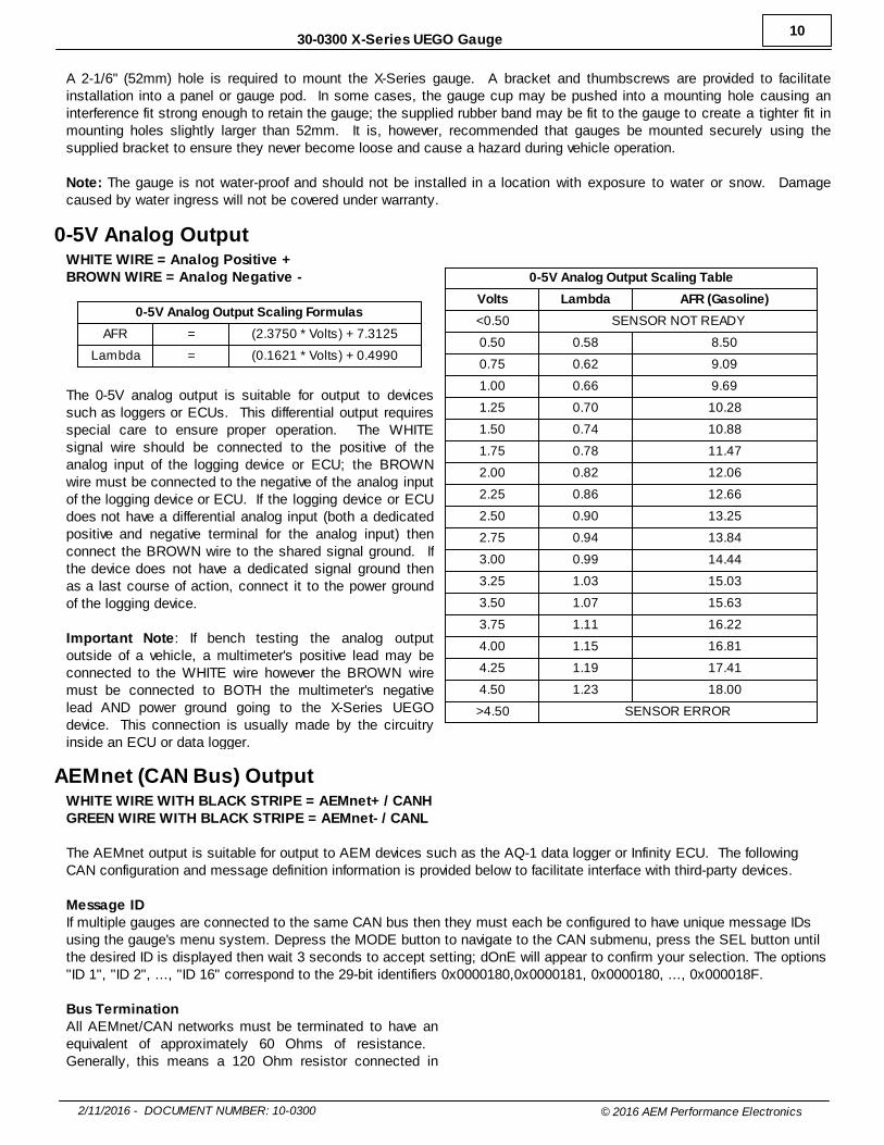
0-5V Analog OutputWHITE WIRE = Analog Positive +BROWN WIRE = Analog Negative -
0-5V Analog Output Scaling Formulas
AFR = (2.3750 * Volts) + 7.3125
Lambda = (0.1621 * Volts) + 0.4990
The 0-5V analog output is suitable for output to devicessuch as loggers or ECUs. This differential output requiresspecial care to ensure proper operation. The WHITEsignal wire should be connected to the positive of theanalog input of the logging device or ECU; the BROWNwire must be connected to the negative of the analog inputof the logging device or ECU. If the logging device or ECUdoes not have a differential analog input (both a dedicatedpositive and negative terminal for the analog input) thenconnect the BROWN wire to the shared signal ground. Ifthe device does not have a dedicated signal ground thenas a last course of action, connect it to the power groundof the logging device.
Important Note: If bench testing the analog outputoutside of a vehicle, a multimeter's positive lead may beconnected to the WHITE wire however the BROWN wiremust be connected to BOTH the multimeter's negativelead AND power ground going to the X-Series UEGOdevice. This connection is usually made by the circuitryinside an ECU or data logger.
0-5V Analog Output Scaling Table
Volts Lambda AFR (Gasoline)
<0.50 SENSOR NOT READY
0.50 0.58 8.50
0.75 0.62 9.09
1.00 0.66 9.69
1.25 0.70 10.28
1.50 0.74 10.88
1.75 0.78 11.47
2.00 0.82 12.06
2.25 0.86 12.66
2.50 0.90 13.25
2.75 0.94 13.84
3.00 0.99 14.44
3.25 1.03 15.03
3.50 1.07 15.63
3.75 1.11 16.22
4.00 1.15 16.81
4.25 1.19 17.41
4.50 1.23 18.00
>4.50 SENSOR ERROR
AEMnet (CAN Bus) OutputWHITE WIRE WITH BLACK STRIPE = AEMnet+ / CANHGREEN WIRE WITH BLACK STRIPE = AEMnet- / CANL
The AEMnet output is suitable for output to AEM devices such as the AQ-1 data logger or Infinity ECU. The followingCAN configuration and message definition information is provided below to facilitate interface with third-party devices.
Message IDIf multiple gauges are connected to the same CAN bus then they must each be configured to have unique message IDsusing the gauge's menu system. Depress the MODE button to navigate to the CAN submenu, press the SEL button untilthe desired ID is displayed then wait 3 seconds to accept setting; dOnE will appear to confirm your selection. The options"ID 1", "ID 2", ..., "ID 16" correspond to the 29-bit identifiers 0x0000180,0x0000181, 0x0000180, ..., 0x000018F.
Bus TerminationAll AEMnet/CAN networks must be terminated to have anequivalent of approximately 60 Ohms of resistance. Generally, this means a 120 Ohm resistor connected in
11
2/11/2016 - DOCUMENT NUMBER: 10-0300 © 2016 AEM Performance Electronics
30-0300 X-Series UEGO Gauge
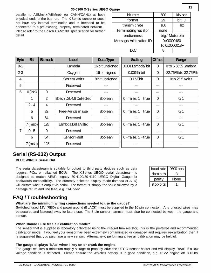
parallel to AEMnet+/AEMnet- (or CANH/CANL) at bothphysical ends of the bus run. The X-Series controller doesnot have any internal termination and is intended to beconnected to a pre-existing, properly terminated network. Please refer to the Bosch CAN2.0B specification for furtherdetail.
bit rate 500 kb/sec
format 29 bit ID
transmit rate 100 hz
terminating resistor none
endianness big / Motorola
Message/Arbitration ID 0x00000180 to 0x0000018F
DLC 8
Byte Bit Bitmask Label Data Type Scaling Offset Range
0-1 Lambda 16 bit unsigned .0001 Lambda/bit 0 0 to 6.5535 Lambda
2-3 Oxygen 16 bit signed 0.001%/bit 0 -32.768% to 32.767%
4 System Volts 8 bit unsigned 0.1 V/bit 0 0 to 25.5 Volts
5 Reserved --- --- --- ---
6 0 (lsb) 0 Reserved --- --- --- ---
1 2 Bosch LSU4.9 Detected Boolean 0 = false, 1 = true 0 0/1
2 - 4 4 Reserved --- --- --- ---
5 32 Free-Air cal in use Boolean 0 = false, 1 = true 0 0/1
6 64 Reserved --- --- --- ---
7 (msb) 128 Lambda Data Valid Boolean 0 = false, 1 = true 0 0/1
7 0 - 5 0 Reserved --- --- --- ---
6 64 Sensor Fault Boolean 0 = false, 1 = true 0 0/1
7 (msb) 128 Reserved --- --- --- ---
Serial (RS-232) OutputBLUE WIRE = Serial Out
The serial datastream is suitable for output to third party devices such as dataloggers, PCs, or reflashed ECUs. The X-Series UEGO serial datastream isdesigned to match AEM's legacy 30-4100/30-4110 UEGO Digital Gauge forbackwards compatibility. The currently selected display mode (lambda or AFR)will dictate what is output via serial. The format is simply the value followed by acarriage return and line feed, e.g. "14.7\r\n"
baud rate 9600 bps
data bits 8
parity None
stop bits 1
FAQ / TroubleshootingWhat are the minimum wiring connections needed to use the gauge?Switched/fused 12V (RED) and power ground (BLACK) must be supplied to the 10 pin connector. Any unused wires maybe secured and fastened away for future use. The 8 pin sensor harness must also be connected between the gauge andsensor.
When should I use free air calibration mode?The sensor that is supplied is laboratory calibrated using the integral trim resistor; this is the preferred and recommendedcalibration mode. If you feel your sensor has been extremely contaminated or damaged and requires re-calibration then itis suggested that you purchase a new sensor. Alternatively, performing a free air calibration may be helpful.
The gauge displays "bAtt" when I key-on or crank the engine.The gauge requires a minimum supply voltage to properly drive the UEGO sensor heater and will display "bAtt" if a lowvoltage condition is detected. Please ensure the vehicle's battery is in good condition, e.g. >12V engine off, >13.8V
12
2/11/2016 - DOCUMENT NUMBER: 10-0300 © 2016 AEM Performance Electronics
30-0300 X-Series UEGO Gauge
engine running.
I installed my gauge correctly and the display just shows four dashes, "- - - -"Four dashes means the sensor is detecting a very lean, high oxygen content higher than 20:1 AFR. This is completelynormal behavior in conditions such as engine off, decel fuel cutoff, or when the sensor is outside of an exhaust in open air. It may also be indicative of an exhaust leak upstream of the sensor, or a sensor installed too close to an open air source,especially if this occurs only at idle and light loads.
I performed a free air calibration but the gauge reported "FAIL"The sensor must be removed from the exhaust to perform a free air calibration. Remove the sensor from the exhaust to afresh air environment that is free from exhaust or chemical/solvent fumes.
My engine has two banks, can I wire two sensors into one gauge and switch between them?No, each sensor must have its own dedicated controller/gauge. Alternatively, the AEM P/N 30-2340 4 Channel WidebandUEGO Controller may suit your needs.
Can I extend the wires in my sensor harness?Yes, but use of at least 20AWG and proper crimping/soldering techniques is required.
My sensor/gauge seems bad, how can I test it?The gauge may be powered from a car battery or bench power supply (3A minimum) to perform this test. Once the gaugeis powered, it should display "SenS" prior to connecting the sensor. Once the sensor is connected, the gauge shoulddisplay the sensor type and indicate it's going through the heat up process. If the sensor is in open air, such as on aworkbench, the gauge should display full lean as indicated by "----" within ~30 seconds. The gas from an unlit butanelighter can be used to simulate a rich condition when introduced to the sensor. A powered sensor will become hot enoughto burn and/or ignite anything flammable -- HANDLE WITH CAUTION. The gauge should visibly sweep rich then lean asthe butane is introduced/removed.
Is the X-Series UEGO controller/sensor compatible with alternative fuels such as E85, methanol, ethanol, CNG,etc?Yes. The lambda display mode and faceplate is recommended when using fuels other than gasoline. The AFR displaymode uses the gasoline stoichiometric ratio of 14.65 which might be confusing for alternative fuels. Remember that AFR= (lambda * stoichiometric ratio).
For support, contact AEM Technical Support at 1-800-423-0046 or [email protected].
12 Month Limited WarrantyAdvanced Engine Management Inc. warrants to the consumer that all AEM High Performance products will be free fromdefects in material and workmanship for a period of twelve (12) months from date of the original purchase. Products thatfail within this 12-month warranty period will be repaired or replaced at AEM’s option, when determined by AEM that theproduct failed due to defects in material or workmanship. This warranty is limited to the repair or replacement of the AEMpart. In no event shall this warranty exceed the original purchase price of the AEM part nor shall AEM be responsible forspecial, incidental or consequential damages or cost incurred due to the failure of this product. Warranty claims to AEMmust be transportation prepaid and accompanied with dated proof of purchase. This warranty applies only to the originalpurchaser of product and is non-transferable. All implied warranties shall be limited in duration to the said 12-monthwarranty period. Improper use or installation, accident, abuse, unauthorized repairs or alterations voids this warranty. AEMdisclaims any liability for consequential damages due to breach of any written or implied warranty on all productsmanufactured by AEM. Warranty returns will only be accepted by AEM when accompanied by a valid Return MerchandiseAuthorization (RMA) number. Product must be received by AEM within 30 days of the date the RMA is issued.
UEGO oxygen sensors are considered wear items and are not covered under warranty.
Please note that before AEM can issue an RMA for any electronic product, it is first necessary for the installer or end userto contact the EMS tech line at 1-800-423-0046 to discuss the problem. Most issues can be resolved over the phone. Under no circumstances should a system be returned or a RMA requested before the above process transpires.
AEM will not be responsible for electronic products that are installed incorrectly, installed in a non-approved application,misused, or tampered with.
13
2/11/2016 - DOCUMENT NUMBER: 10-0300 © 2016 AEM Performance Electronics
30-0300 X-Series UEGO Gauge
Any AEM electronics product can be returned for repair if it is out of the warranty period. There is a minimum charge of$50.00 for inspection and diagnosis of AEM electronic parts. Parts used in the repair of AEM electronic components willbe extra. AEM will provide an estimate of repairs and receive written or electronic authorization before repairs are made tothe product.
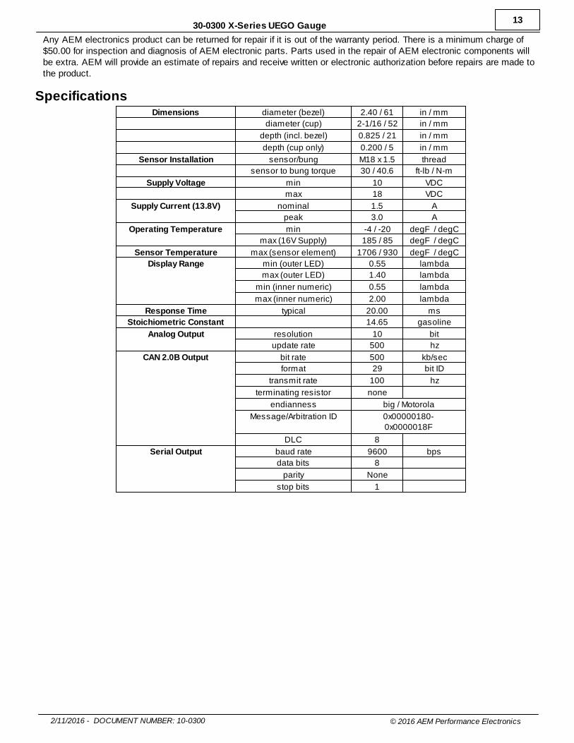
SpecificationsDimensions diameter (bezel) 2.40 / 61 in / mm
diameter (cup) 2-1/16 / 52 in / mm
depth (incl. bezel) 0.825 / 21 in / mm
depth (cup only) 0.200 / 5 in / mm
Sensor Installation sensor/bung M18 x 1.5 thread
sensor to bung torque 30 / 40.6 ft-lb / N-m
Supply Voltage min 10 VDC
max 18 VDC
Supply Current (13.8V) nominal 1.5 A
peak 3.0 A
Operating Temperature min -4 / -20 degF / degC
max (16V Supply) 185 / 85 degF / degC
Sensor Temperature max (sensor element) 1706 / 930 degF / degC
Display Range min (outer LED) 0.55 lambda
max (outer LED) 1.40 lambda
min (inner numeric) 0.55 lambda
max (inner numeric) 2.00 lambda
Response Time typical 20.00 ms
Stoichiometric Constant 14.65 gasoline
Analog Output resolution 10 bit
update rate 500 hz
CAN 2.0B Output bit rate 500 kb/sec
format 29 bit ID
transmit rate 100 hz
terminating resistor none
endianness big / Motorola
Message/Arbitration ID 0x00000180-0x0000018F
DLC 8
Serial Output baud rate 9600 bps
data bits 8
parity None
stop bits 1


![Untitled-1 [] · YT.. 0300 YT.. 0300 YT.. 0300 YT.. 0300. Title: Untitled-1 Author: Eyup Created Date: 4/4/2016 11:28:30 AM](https://static.fdocuments.us/doc/165x107/5f24e2450a7e2c6cc2663645/untitled-1-yt-0300-yt-0300-yt-0300-yt-0300-title-untitled-1-author.jpg)