3: Transport Layer3b-1 Chapter 3: Transport Layer Part B Course on Computer Communication and...
42
3: Transport Layer 3b-1 Chapter 3: Transport Layer Part B Course on Computer Communication and Networks, CTH/GU The slides are adaptation of the slides made available by the authors of the course’s main textbook
-
date post
19-Dec-2015 -
Category
Documents
-
view
219 -
download
3
Transcript of 3: Transport Layer3b-1 Chapter 3: Transport Layer Part B Course on Computer Communication and...

3: Transport Layer 3b-1
Chapter 3: Transport LayerPart B
Course on Computer Communication and Networks, CTH/GU
The slides are adaptation of the slides made available by the authors of the course’s main textbook

3: Transport Layer 3b-2
Pipelining: increased utilizationAck-based => flowcontrol
first packet bit transmitted, t = 0
sender receiver
RTT
last bit transmitted, t = L / R
first packet bit arriveslast packet bit arrives, send ACK
ACK arrives, send next packet, t = RTT + L / R
last bit of 2nd packet arrives, send ACKlast bit of 3rd packet arrives, send ACK
U sender
= .024
30.008 = 0.0008
microseconds
3 * L / R
RTT + L / R =
Increase utilizationby a factor of 3!
3: Transport Layer 3b-3
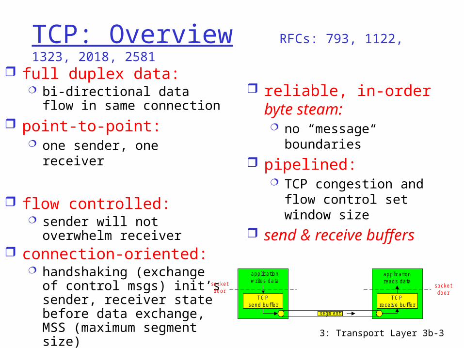
TCP: Overview RFCs: 793, 1122, 1323, 2018, 2581
full duplex data: bi-directional data flow in
same connection point-to-point:
one sender, one receiver
flow controlled: sender will not overwhelm
receiver connection-oriented:
handshaking (exchange of control msgs) init’s sender, receiver state before data exchange, MSS (maximum segment size)
reliable, in-order byte steam: no “message
boundaries” pipelined:
TCP congestion and flow control set window size
send & receive buffers
socketdoor
T C Psend buffer
T C Preceive buffer
socketdoor
segm ent
applicationwrites data
applicationreads data

3: Transport Layer 3b-4
TCP Flow Control: Dynamic sliding windows
receiver: explicitly informs sender of (dynamically changing) amount of free buffer space RcvWindow field
in TCP segmentsender: keeps the
amount of transmitted, unACKed data less than most recently received RcvWindow
sender won’t overrun
receiver’s buffers bytransmitting too
much, too fast
flow control
receiver buffering
RcvBuffer = size or TCP Receive Buffer
RcvWindow = amount of spare room in Buffer
3: Transport Layer 3b-5
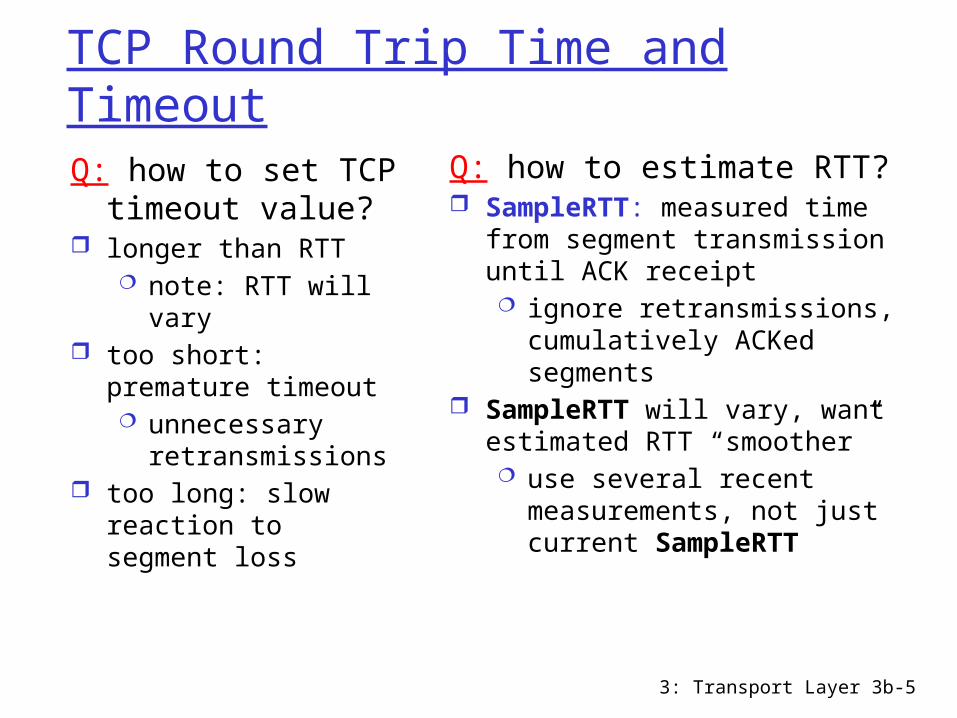
TCP Round Trip Time and TimeoutQ: how to set TCP
timeout value? longer than RTT
note: RTT will vary too short: premature
timeout unnecessary
retransmissions too long: slow
reaction to segment loss
Q: how to estimate RTT? SampleRTT: measured time
from segment transmission until ACK receipt ignore retransmissions,
cumulatively ACKed segments
SampleRTT will vary, want estimated RTT “smoother” use several recent
measurements, not just current SampleRTT
3: Transport Layer 3b-6
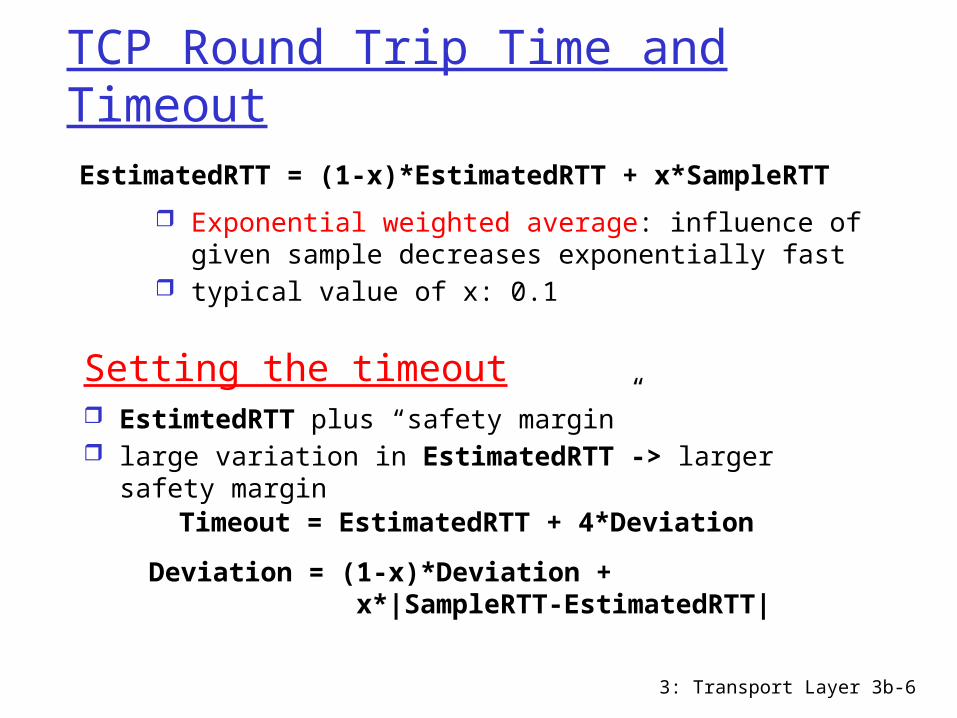
TCP Round Trip Time and TimeoutEstimatedRTT = (1-x)*EstimatedRTT + x*SampleRTT
Exponential weighted average: influence of given sample decreases exponentially fast
typical value of x: 0.1
Setting the timeout EstimtedRTT plus “safety margin” large variation in EstimatedRTT -> larger safety
marginTimeout = EstimatedRTT + 4*Deviation
Deviation = (1-x)*Deviation + x*|SampleRTT-EstimatedRTT|

3: Transport Layer 3b-7
Example RTT estimation:RTT: gaia.cs.umass.edu to fantasia.eurecom.fr
100
150
200
250
300
350
1 8 15 22 29 36 43 50 57 64 71 78 85 92 99 106
time (seconnds)
RTT
(mill
isec
onds
)
SampleRTT Estimated RTT

3: Transport Layer 3b-8
TCP seq. #’s and ACKsSeq. #’s: byte stream
“number” of first byte in segment’s data initially random (to min.
probability of conflict, with “historical” segments, buffered in the network)
recycling sequence numbers?
ACKs: seq # of next byte expected from other side cumulative ACK
Host A Host B
Seq=42, ACK=79, data = ‘C’
Seq=79, ACK=43, data = ‘C’
Seq=43, ACK=80
Usertypes
‘C’
host ACKsreceipt
of echoed‘C’
host ACKsreceipt of
‘C’, echoesback ‘C’
timesimple telnet scenario
3: Transport Layer 3b-9
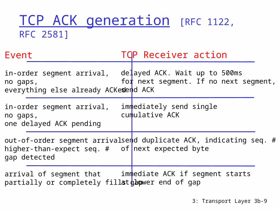
TCP ACK generation [RFC 1122, RFC 2581]
Event
in-order segment arrival, no gaps,everything else already ACKed
in-order segment arrival, no gaps,one delayed ACK pending
out-of-order segment arrivalhigher-than-expect seq. #gap detected
arrival of segment that partially or completely fills gap
TCP Receiver action
delayed ACK. Wait up to 500msfor next segment. If no next segment,send ACK
immediately send singlecumulative ACK
send duplicate ACK, indicating seq. #of next expected byte
immediate ACK if segment startsat lower end of gap

3: Transport Layer 3b-10
TCP: retransmission scenaria
Host A
Seq=92, 8 bytes data
ACK=100
loss
tim
eout
time lost ACK scenario
Host B
X
Seq=92, 8 bytes data
ACK=100
Host A
Seq=100, 20 bytes data
ACK=100
Seq=
92
tim
eout
time premature timeout,cumulative ACKs
Host B
Seq=92, 8 bytes data
ACK=120
Seq=92, 8 bytes data
Seq=
10
0 t
imeou
t
ACK=120
3: Transport Layer 3b-11
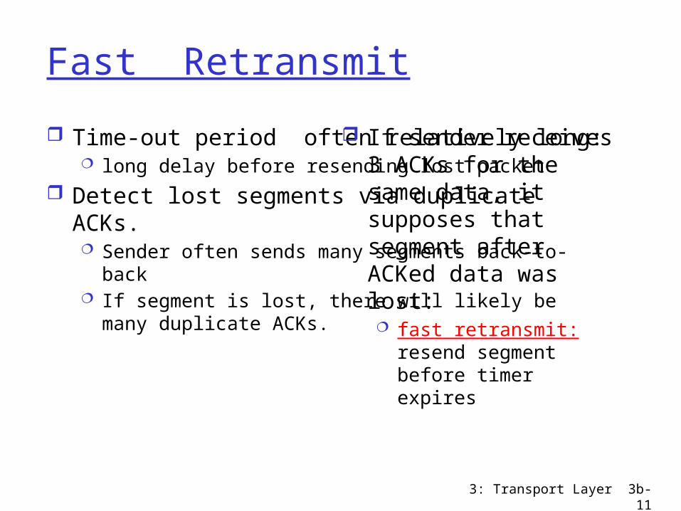
Fast Retransmit
Time-out period often relatively long: long delay before resending lost packet
Detect lost segments via duplicate ACKs. Sender often sends many segments back-to-back If segment is lost, there will likely be many duplicate
ACKs.
If sender receives 3 ACKs for the same data, it supposes that segment after ACKed data was lost: fast retransmit: resend
segment before timer expires
3: Transport Layer 3b-12
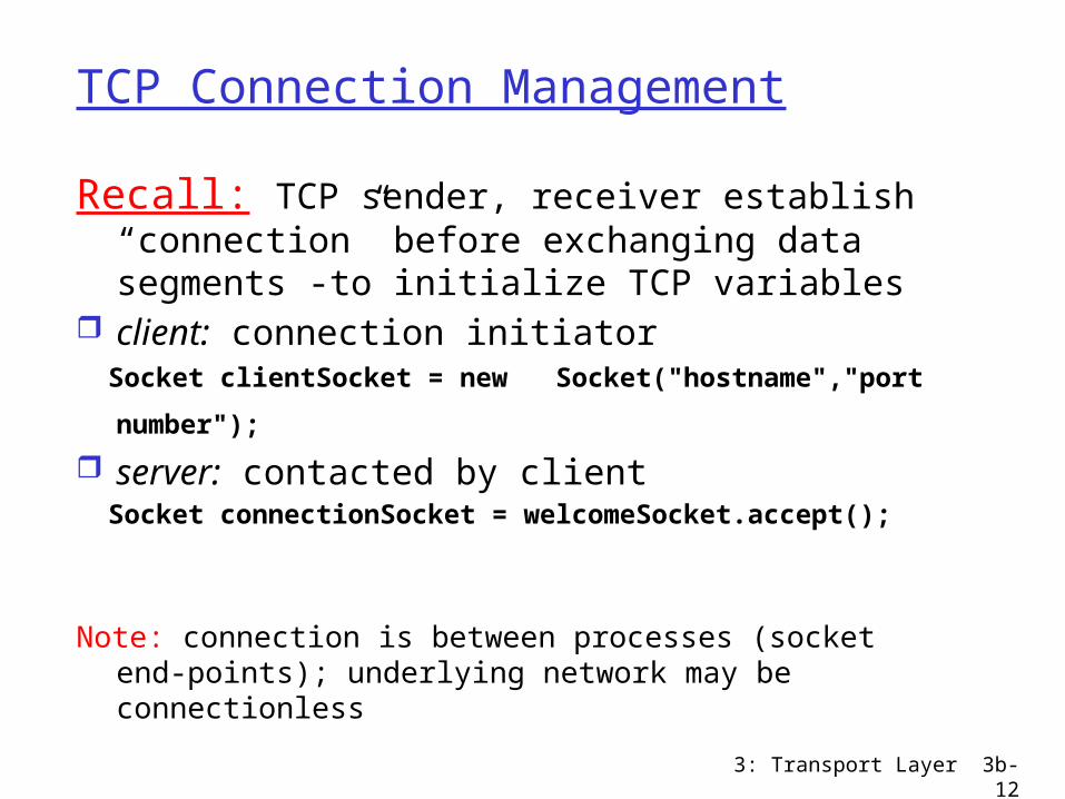
TCP Connection Management
Recall: TCP sender, receiver establish “connection” before exchanging data segments -to initialize TCP variables
client: connection initiator Socket clientSocket = new Socket("hostname","port
number"); server: contacted by client Socket connectionSocket = welcomeSocket.accept();
Note: connection is between processes (socket end-points); underlying network may be connectionless
3: Transport Layer 3b-13
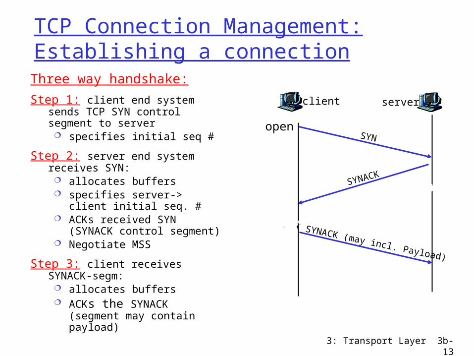
TCP Connection Management: Establishing a connectionThree way handshake:
Step 1: client end system sends TCP SYN control segment to server
specifies initial seq #
Step 2: server end system receives SYN:
allocates buffers specifies server-> client
initial seq. # ACKs received SYN (SYNACK
control segment) Negotiate MSS
Step 3: client receives SYNACK-segm:
allocates buffers ACKs the SYNACK (segment
may contain payload)
client
SYN
server
SYNACK
ACK SYNACK (may incl. Payload)
open

3: Transport Layer 3b-14
TCP Connection Management: Closing a connectionRequires distributed agreement (cf.
also Byzantine generals problem)
client closes socket: clientSocket.close();
Step 1: client end system sends TCP FIN control segment to server
Step 2: server receives FIN, replies with ACK. (Possibly has more data to send; then closes connection, sends FIN.
Step 3: client receives FIN, replies with ACK. Enters “timed wait” (needed to be able to respond with ACK to received FINs, if first ACK was lost)
Step 4: server, receives ACK. Connection closed.
client
FIN
server
ACK
ACK
FIN
close
close
closed
tim
ed w
ait
data
ACK
3: Transport Layer 3b-15
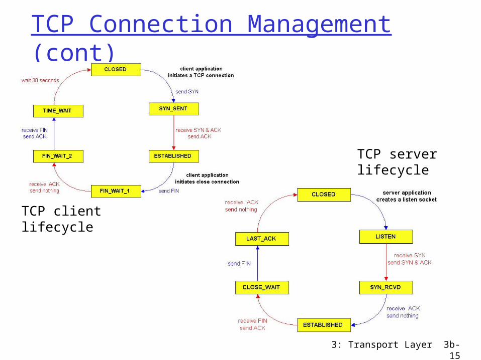
TCP Connection Management (cont)
TCP clientlifecycle
TCP serverlifecycle
3: Transport Layer 3b-16
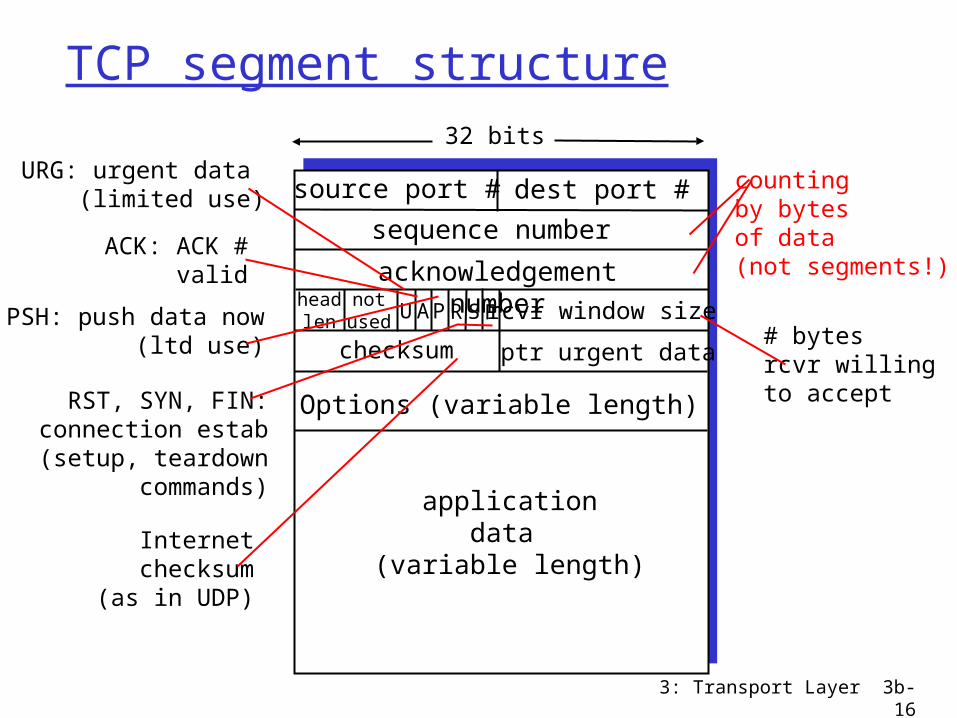
TCP segment structure
source port # dest port #
32 bits
applicationdata
(variable length)
sequence number
acknowledgement numberrcvr window size
ptr urgent datachecksum
FSRPAUheadlen
notused
Options (variable length)
URG: urgent data (limited use)
ACK: ACK #valid
PSH: push data now(ltd use)
RST, SYN, FIN:connection estab(setup, teardown
commands)
# bytes rcvr willingto accept
countingby bytes of data(not segments!)
Internetchecksum
(as in UDP)
3: Transport Layer 3b-17
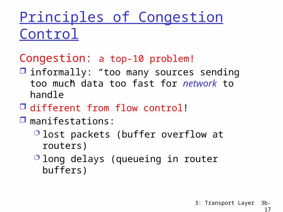
Principles of Congestion Control
Congestion: a top-10 problem! informally: “too many sources sending too
much data too fast for network to handle” different from flow control! manifestations:
lost packets (buffer overflow at routers) long delays (queueing in router buffers)

3: Transport Layer 3b-18
Causes/costs of congestion: scenario 1
two senders, two receivers
one router, infinite buffers
no retransmission
large delays when congested
maximum achievable throughput
unlimited shared output link buffers
Host Alin : original data
Host B
lout
3: Transport Layer 3b-19
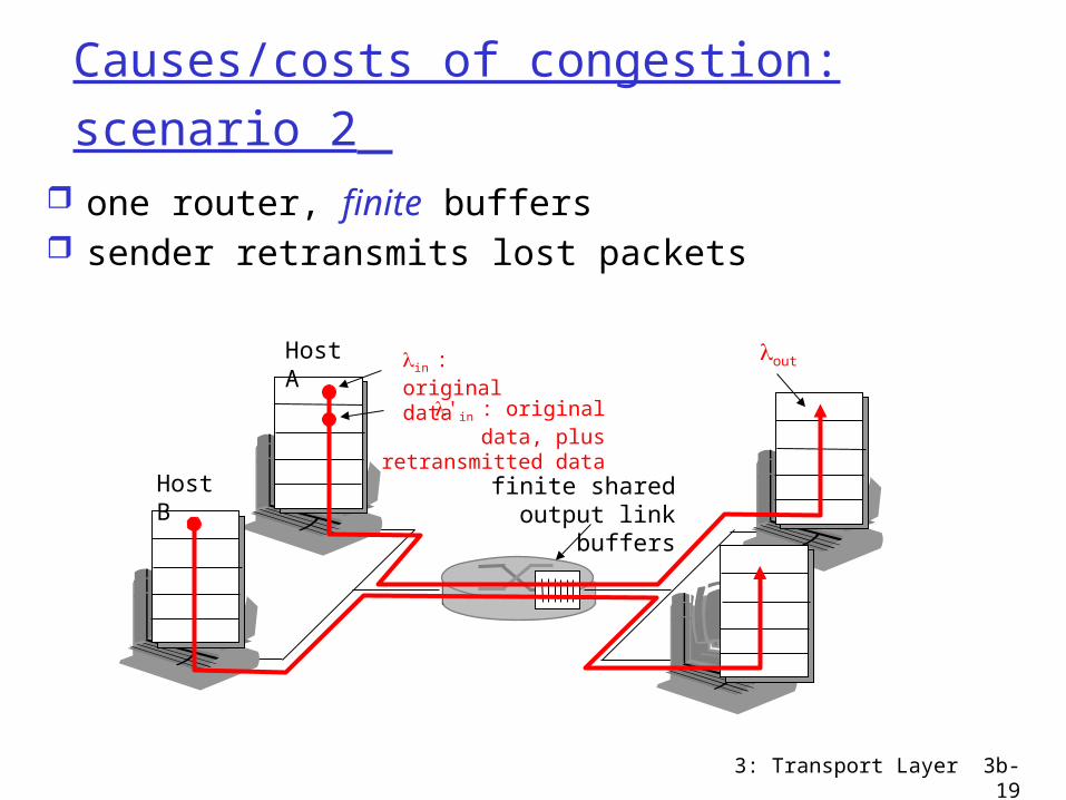
Causes/costs of congestion: scenario 2
one router, finite buffers sender retransmits lost packets
finite shared output link buffers
Host A lin : original data
Host B
lout
l'in : original data, plus retransmitted data

3: Transport Layer 3b-20
Causes/costs of congestion: scenario 2 always: (goodput)
“perfect” retransmission only when loss:
retransmission of delayed (not lost) packet makes
larger (than perfect case) for same
lin
lout
=
lin
lout
>
linl
out
“costs” of congestion: (more congestion ) more work (retrans) for given “goodput” unneeded retransmissions: link carries multiple copies of
pkt
3: Transport Layer 3b-21
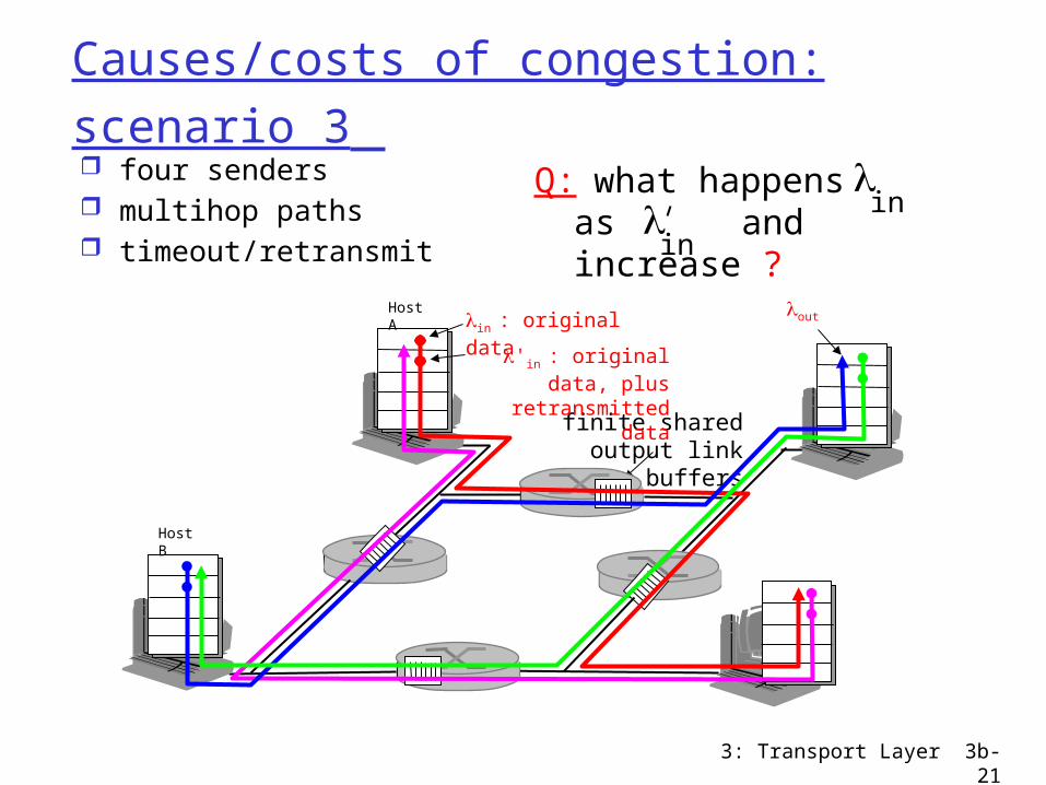
Causes/costs of congestion: scenario 3 four senders multihop paths timeout/retransmit
lin
Q: what happens as and increase ?
lin
finite shared output link buffers
Host Alin : original data
Host B
lout
l'in : original data, plus retransmitted data

3: Transport Layer 3b-22
Causes/costs of congestion: scenario 3
Another “cost” of congestion: when packet dropped, any “upstream
transmission capacity used for that packet was wasted!
Host A
Host B
lo
u
t

3: Transport Layer 3b-23
Summary causes of Congestion:
Bad network design (bottlenecks) Bad use of network : feed with more than can
go through … congestion (bad congestion-control
policies e.g. dropping the wrong packets, etc)

3: Transport Layer 3b-24
Two broad approaches towards congestion control
End-end congestion control:
no explicit feedback from network
congestion inferred from end-system observed loss, delay
approach taken by TCP (focus here)
Network-assisted congestion control:
routers provide feedback to end systems single bit indicating
congestion (SNA, DECbit, TCP/IP ECN, ATM)
explicit rate sender should send at
routers may serve flows with parameters, may also apply admission control on connection-request
(see later, in assoc. with N/W layer, ATM policies, multimedia apps & QoS, match of traffic needs with use of the N/W)
3: Transport Layer 3b-25
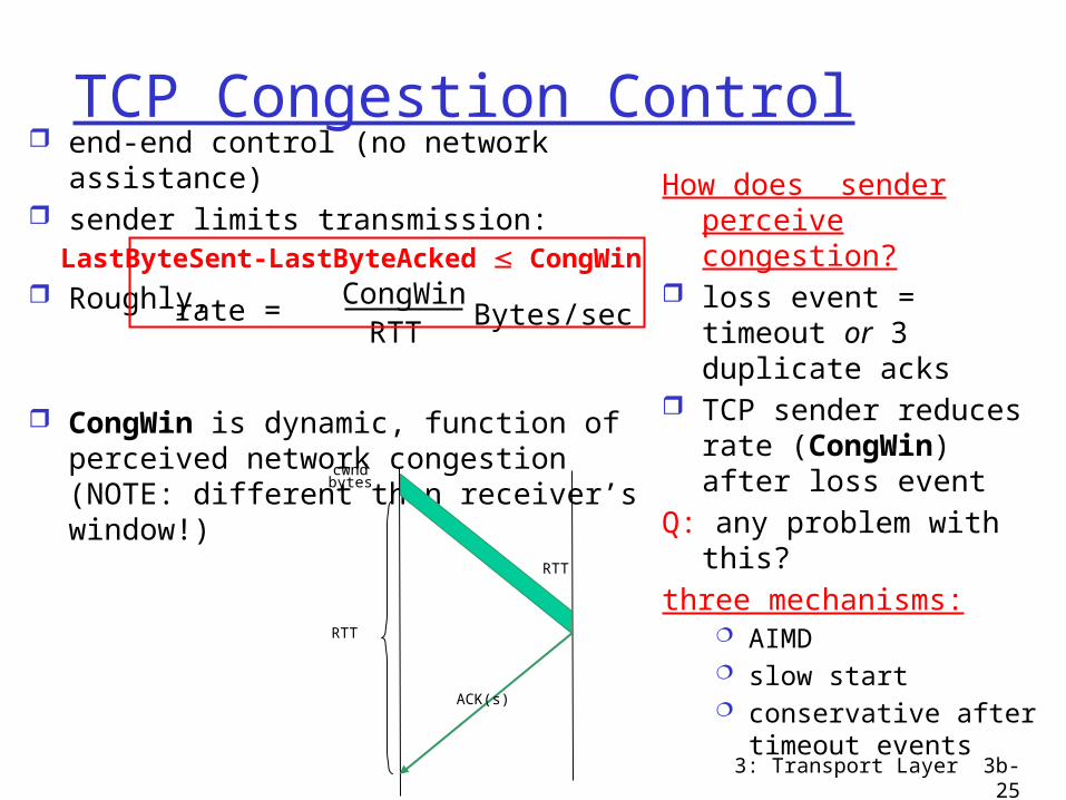
TCP Congestion Control end-end control (no network
assistance) sender limits transmission: LastByteSent-LastByteAcked CongWin Roughly,
CongWin is dynamic, function of perceived network congestion (NOTE: different than receiver’s window!)
How does sender perceive congestion?
loss event = timeout or 3 duplicate acks
TCP sender reduces rate (CongWin) after loss event
Q: any problem with this? three mechanisms:
AIMD slow start conservative after
timeout events
rate = CongWin
RTT Bytes/sec
RTT
cwndbytes
RTT
ACK(s)
3: Transport Layer 3b-26
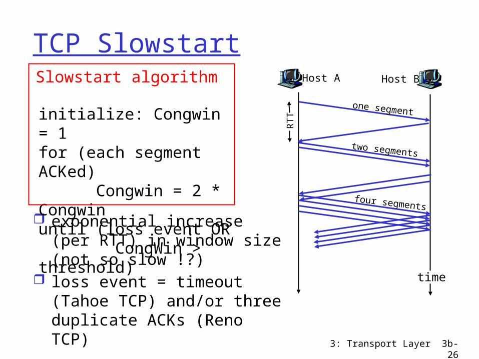
TCP Slowstart
exponential increase (per RTT) in window size (not so slow !?)
loss event = timeout (Tahoe TCP) and/or three duplicate ACKs (Reno TCP)
initialize: Congwin = 1for (each segment ACKed) Congwin = 2 * Congwinuntil (loss event OR CongWin > threshold)
Slowstart algorithm Host A
one segment
RTT
Host B
time
two segments
four segments
3: Transport Layer 3b-27
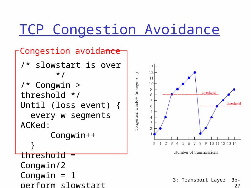
TCP Congestion Avoidance
/* slowstart is over */ /* Congwin > threshold */Until (loss event) { every w segments ACKed: Congwin++ }threshold = Congwin/2Congwin = 1perform slowstart
Congestion avoidance

3: Transport Layer 3b-28
Refinement (Reno)
Avoid slow starts!Go to linear increase
after 3rd duplicate ack, starting from window of size (1/2 window before change)
3: Transport Layer 3b-29
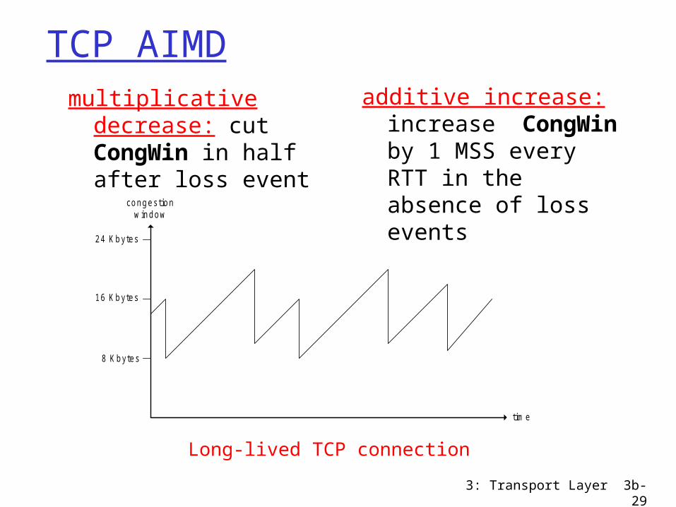
TCP AIMD
8 Kbytes
16 Kbytes
24 Kbytes
time
congestionwindow
multiplicative decrease: cut CongWin in half after loss event
additive increase: increase CongWin by 1 MSS every RTT in the absence of loss events
Long-lived TCP connection
3: Transport Layer 3b-30
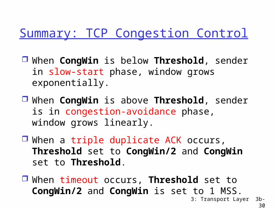
Summary: TCP Congestion Control
When CongWin is below Threshold, sender in slow-start phase, window grows exponentially.
When CongWin is above Threshold, sender is in congestion-avoidance phase, window grows linearly.
When a triple duplicate ACK occurs, Threshold set to CongWin/2 and CongWin set to Threshold.
When timeout occurs, Threshold set to CongWin/2 and CongWin is set to 1 MSS.

3: Transport Layer 3b-31
TCP sender congestion control
Event State TCP Sender Action Commentary
ACK receipt for previously unacked data
Slow Start (SS)
CongWin = CongWin + MSS, If (CongWin > Threshold) set state to “Congestion Avoidance”
Resulting in a doubling of CongWin every RTT
ACK receipt for previously unacked data
CongestionAvoidance (CA)
CongWin = CongWin+MSS * (MSS/CongWin)
Additive increase, resulting in increase of CongWin by 1 MSS every RTT
Loss event detected by triple duplicate ACK
SS or CA Threshold = CongWin/2, CongWin = Threshold,Set state to “Congestion Avoidance”
Fast recovery, implementing multiplicative decrease. CongWin will not drop below 1 MSS.
Timeout SS or CA Threshold = CongWin/2, CongWin = 1 MSS,Set state to “Slow Start”
Enter slow start
Duplicate ACK
SS or CA Increment duplicate ACK count for segment being acked
CongWin and Threshold not changed
3: Transport Layer 3b-32
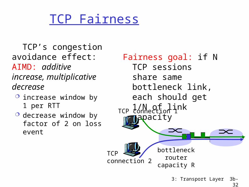
TCP Fairness
Fairness goal: if N TCP sessions share same bottleneck link, each should get 1/N of link capacity
TCP’s congestion avoidance effect: AIMD: additive increase, multiplicative decrease increase window by 1
per RTT decrease window by
factor of 2 on loss event
TCP connection 1
bottleneckrouter
capacity R
TCP connection 2
3: Transport Layer 3b-33
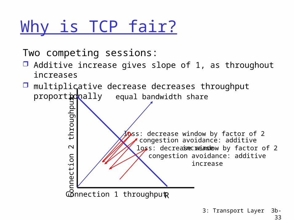
Why is TCP fair?
Two competing sessions: Additive increase gives slope of 1, as throughout increases multiplicative decrease decreases throughput proportionally
R
R
equal bandwidth share
Connection 1 throughputConnect
ion 2
th
roughput
congestion avoidance: additive increaseloss: decrease window by factor of 2
congestion avoidance: additive increaseloss: decrease window by factor of 2

3: Transport Layer 3b-34
Fairness (more)
Fairness and UDP Multimedia apps
often do not use TCP do not want rate
throttled by congestion control
Instead use UDP: pump audio/video at
constant rate, tolerate packet loss
Research area: TCP friendly
Fairness and parallel TCP connections
nothing prevents app from opening parallel cnctions between 2 hosts.
Web browsers do this ….
3: Transport Layer 3b-35
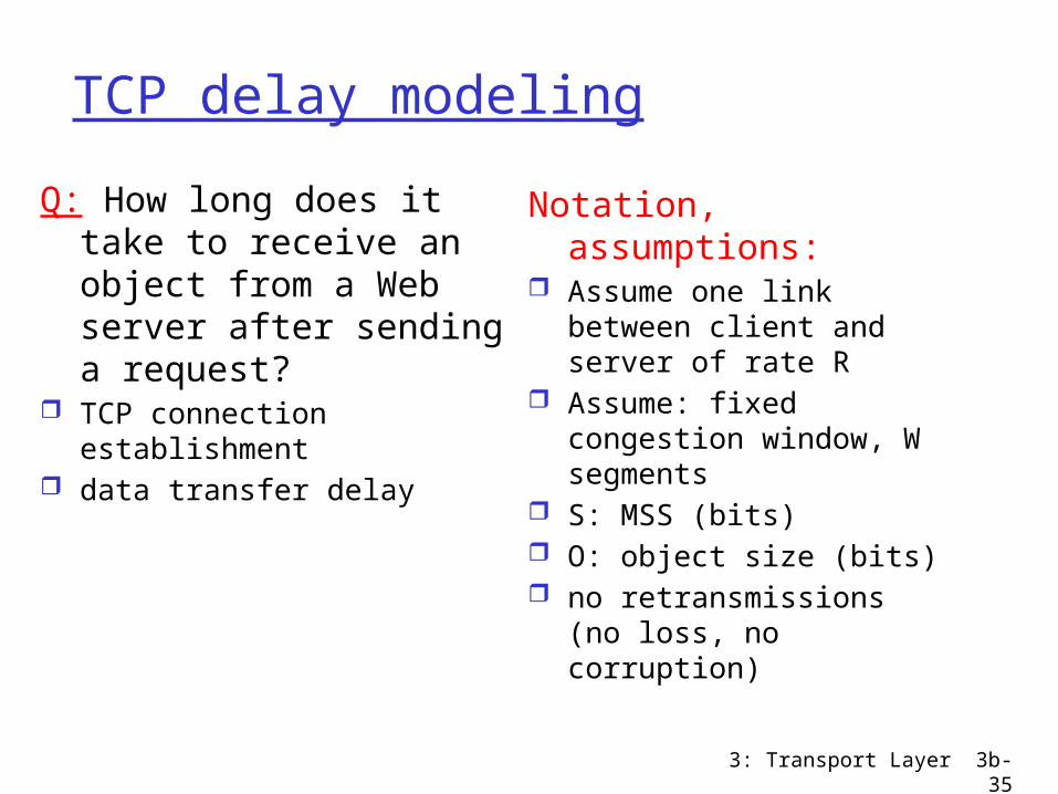
TCP delay modeling
Q: How long does it take to receive an object from a Web server after sending a request?
TCP connection establishment
data transfer delay
Notation, assumptions: Assume one link between
client and server of rate R
Assume: fixed congestion window, W segments
S: MSS (bits) O: object size (bits) no retransmissions (no
loss, no corruption)

3: Transport Layer 3b-36
TCP delay Modeling: Fixed window
Case 1: WS/R > RTT + S/R: ACK for first segment in window returns before window’s worth of data sentlatency = 2RTT + O/R
Case 2: WS/R < RTT + S/R: wait for ACK after sending window’s worth of data sentlatency = 2RTT + O/R
+ (K-1)[S/R + RTT - WS/R]
K:= O/WS
3: Transport Layer 3b-37
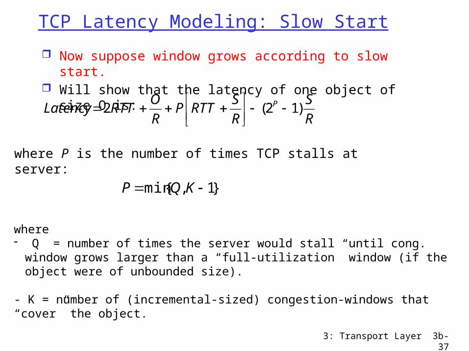
TCP Latency Modeling: Slow Start
Now suppose window grows according to slow start. Will show that the latency of one object of size O is:
R
S
R
SRTTP
R
ORTTLatency P )12(2
where P is the number of times TCP stalls at server:
}1,{min KQP
where - Q = number of times the server would stall until cong. window grows
larger than a “full-utilization” window (if the object were of unbounded size).
- K = number of (incremental-sized) congestion-windows that “cover” the object.
3: Transport Layer 3b-38
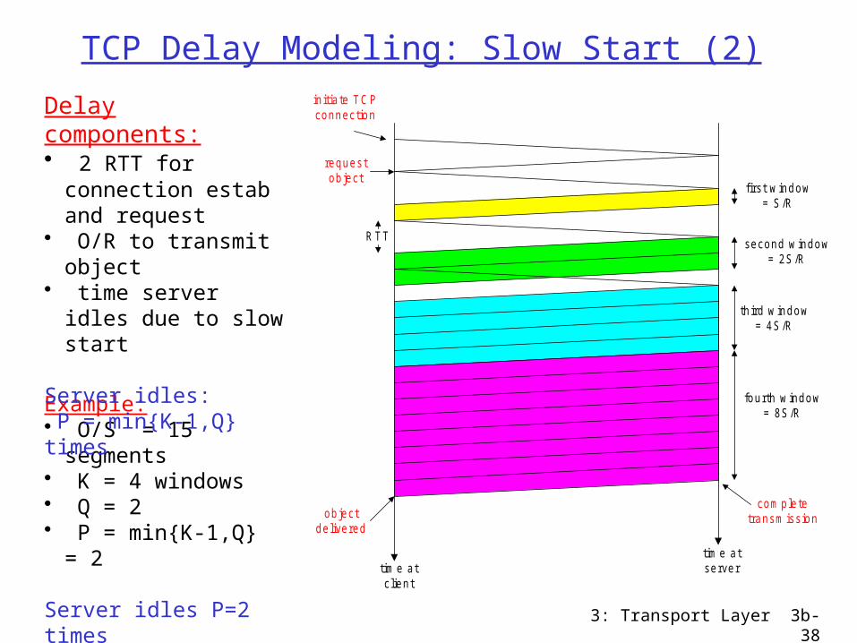
TCP Delay Modeling: Slow Start (2)
RTT
initia te TCPconnection
requestobject
first w indow= S /R
second w indow= 2S /R
third w indow= 4S /R
fourth w indow= 8S /R
com pletetransm issionobject
delivered
tim e atc lient
tim e atserver
Example:• O/S = 15
segments• K = 4 windows• Q = 2• P = min{K-1,Q} =
2
Server idles P=2 times
Delay components:• 2 RTT for
connection estab and request
• O/R to transmit object
• time server idles due to slow start
Server idles: P = min{K-1,Q} times

3: Transport Layer 3b-39
TCP Delay Modeling (3)
R
S
R
SRTTPRTT
R
O
R
SRTT
R
SRTT
R
O
idleTimeRTTR
O
P
kP
k
P
pp
)12(][2
]2[2
2delay
1
1
1
th window after the timeidle 2 1 kR
SRTT
R
S k
ementacknowledg receivesserver until
segment send tostartsserver whenfrom time RTTR
S
window kth the transmit totime2 1
R
Sk
RTT
initia te TCPconnection
requestobject
first w indow= S /R
second w indow= 2S /R
third w indow= 4S /R
fourth w indow= 8S /R
com pletetransm issionobject
delivered
tim e atc lient
tim e atserver
3: Transport Layer 3b-40
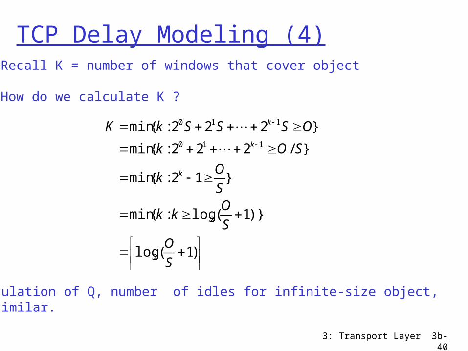
TCP Delay Modeling (4)
)1(log
)}1(log:{min
}12:{min
}/222:{min
}222:{min
2
2
110
110
S
OS
Okk
S
Ok
SOk
OSSSkK
k
k
k
Calculation of Q, number of idles for infinite-size object,is similar.
Recall K = number of windows that cover object
How do we calculate K ?

3: Transport Layer 3b-41
Wireless TCPProblem: higher data error-rate destroys congestion
control principle (assumption)
Possible solutions: Non-transparent (indirect): manage congestion-
control in 2 sub-connections (one wired, one wireless). But … the semantics of a connection changes: ack at the sender means that base-station, (not the receiver) received the segment
Transpartent: use extra rules at the base-station (network layer retransmissions...) to ”hide” the errors of the wireless part from the sender. But … the sender may still timeout in the meanwhile and think that there is congestion ...
Vegas algorithm: observe RTT estimation and reduce transmission rate when in danger of loss
3: Transport Layer 3b-42
Chapter 3: Summary
principles behind transport layer services: multiplexing/
demultiplexing reliable data transfer flow control congestion control
instantiation and implementation in the Internet UDP TCP
Next: leaving the network
“edge” (application transport layer)
into the network “core”