3. Stresses in Machine Elements Lecture Number – 3.1 Prof. Dr. C. S. Pathak Department of...
21
3. Stresses in Machine Elements Lecture Number – 3.1 Prof. Dr. C. S. Pathak Department of Mechanical Engineering Sinhgad College of Engineering, Pune Strength of Materials
-
Upload
polly-anthony -
Category
Documents
-
view
220 -
download
3
Transcript of 3. Stresses in Machine Elements Lecture Number – 3.1 Prof. Dr. C. S. Pathak Department of...

Strength of Materials
3. Stresses in Machine Elements
Lecture Number – 3.1Prof. Dr. C. S. Pathak
Department of Mechanical EngineeringSinhgad College of Engineering, Pune
Strength of Materials
Agenda
• Theory of Simple Bending • Assumptions• Derivation • 1 Illustrative Numerical • 1 Workout Example
Beam Subjected to Pure Bending

Strength of Materials
Assumptions
1. The beam is initially straight and unstressed2. The material is homogeneous and isotropic3. The beam loaded within elastic limit4. Young’s modulus is same in tension and compression5. Plane cross–section remains plane before and after bending6. Each layer of the beam is free to expand or contract7. Radius of curvature is large compared with dimension of cross sections

Strength of Materials
Bending Deformations
• bends uniformly to form a circular arc
• cross-sectional plane passes through arc center and remains planar
• length of top decreases and length of bottom increases
• a neutral surface must exist that is parallel to the upper and lower surfaces and for which the length does not change
• stresses and strains are negative (compressive) above the neutral plane and positive (tension) below it
• member remains symmetric

Strength of Materials
Derivation
• Constant BM is applied• Beam will bend @ O, R• tension, compression
Ref – Strength of Materials by Dr. R. K. Bansal, Laxmi Publications
Strength of Materials
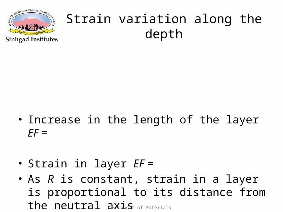
Strain variation along the depth
• Increase in the length of the layer EF =
• Strain in layer EF = • As R is constant, strain in a layer is proportional to its
distance from the neutral axis

Strength of Materials
Stress variation
• Let,
• Rewriting
• Variation of strain and stress is linear
Strength of Materials
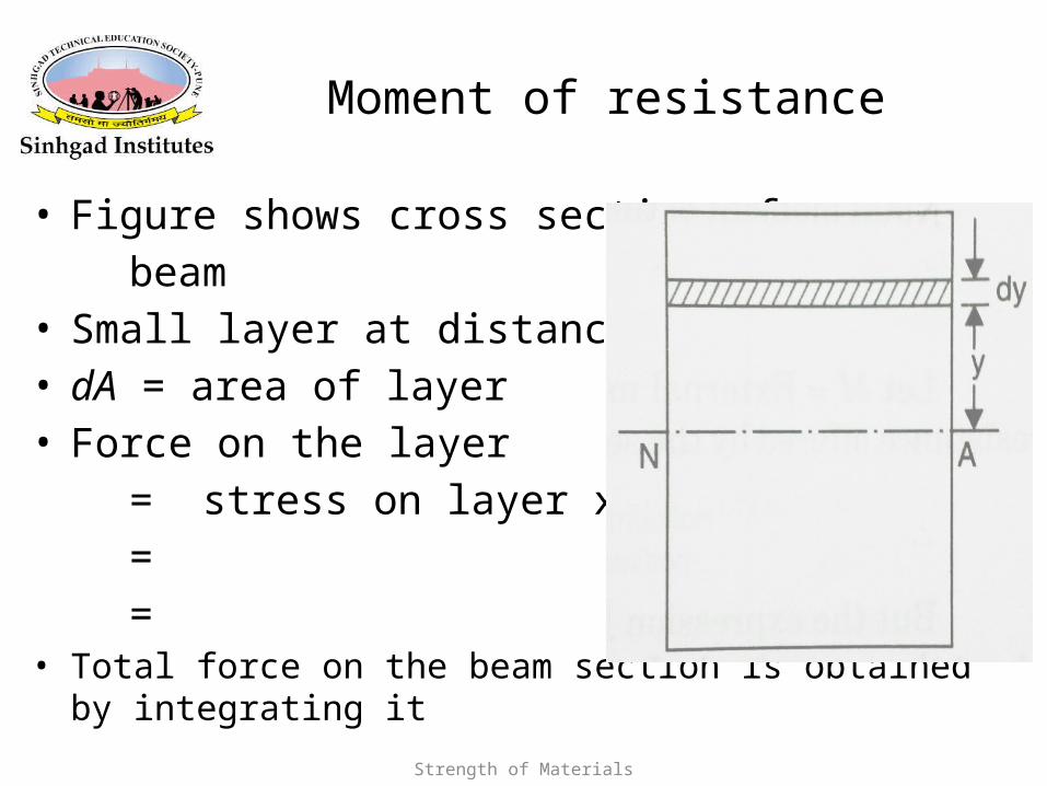
Moment of resistance
• Figure shows cross section of a beam• Small layer at distance y• dA = area of layer• Force on the layer = stress on layer x area of layer = = • Total force on the beam section is obtained by integrating it

Strength of Materials
Derivation continued….
• Moment of the force on the layer about N.A.
• Total moment of the forces on the section of the beam

Strength of Materials
Bending equation
• Let M = external moment applied on the beam section• For equilibrium moment of resistance = M• M = • The term represents moment of inertia @ NA

Strength of Materials
Moment of Inertia
• Moment of inertia is • a measure of the resistance of the section to – applied moment or – load that tends to bend it.
• Moment of inertia depends on shape and not material• It is a derived property

Strength of Materials
Loading Pattern

Strength of Materials
𝜋
𝜋
𝜋

Strength of Materials
Section Modulus

Strength of Materials

Strength of Materials

Strength of Materials
Illustrative Example
A cast-iron machine part is acted upon by a 3 kN-m couple. Knowing E = 165 GPa and neglecting the effects of fillets, determine
(a) the maximum tensile and compressive stresses,
(b) the radius of curvature.
Ref:- Mechanics of Materials by Beer and Johnston

Strength of Materials
SOLUTION
• Based on the cross section geometry, calculate the location of the section centroid and moment of inertia.
2dAIIA
AyY x
• Apply the elastic flexural formula to find the maximum tensile and compressive stresses.
I
Mcm
• Calculate the curvature
EI
M
R
1

Strength of Materials
SOLUTION
Based on the cross section geometry, calculate the location of the section centroid and moment of inertia.
mm 383000
10114 3
A
AyY
3
3
3
32
101143000
104220120030402
109050180090201
mm ,mm ,mm Area,
AyA
Ayy
49-3
2312123
121
231212
m10868 mm10868
18120040301218002090
I
dAbhdAIIx

Strength of Materials
SOLUTION
49
49
mm10868
m038.0mkN 3mm10868
m022.0mkN 3
I
cM
I
cMI
Mc
BB
AA
m
MPa 0.76A
MPa 3.131B
• Calculate the curvature
49- m10868GPa 165
mkN 3
1
EI
M
R
m 7.47
m1095.201 1-3
RR
• Apply the elastic flexural formula to find the maximum tensile and compressive stresses.