3 STM32F3 Hands-On Workshop 59homepage.cem.itesm.mx/carbajal/Microcontrollers/SLIDES/STM32F… ·...
58
STM32F3 Hands-On Workshop
Transcript of 3 STM32F3 Hands-On Workshop 59homepage.cem.itesm.mx/carbajal/Microcontrollers/SLIDES/STM32F… ·...

STM32F3 Hands-On Workshop
Welcome – Hands-On 2
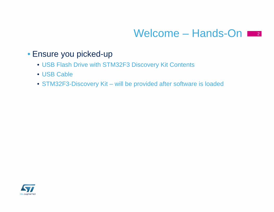
• Ensure you picked-up• USB Flash Drive with STM32F3 Discovery Kit Contents• USB Cable• STM32F3-Discovery Kit – will be provided after software is loaded

Keil uVision IDE Installation

Systems Check
• Everyone should have• A Windows ® Laptop (XP, Vista, or Windows 7)• USB Cable• USB Flash Drive• STM32F3-DISCOVERY kit: provided during the software installation.
• Ready to begin?
Note: please do not attempt to plug in the STM32F3-Discovery Kit into your laptop until instructed to do so.
4

Step #1 - File Installation
• Insert the USB Flash Drive into your Laptop
• Copy the folder “…\STM32F3DISCOVERY_Kit” on the USB flash drive to your root “c:\” folder
• C:\STM32F3DISCOVERY_Kit\• Edit folder properties and remove ‘Read-only’ attribute for all sub-folders.
• Open this directory and you will find the following:• Keil µVision v4.71 IDE tool installation application and license file.• Docs STM32F3 Datasheets, Programming Manual, Reference
Manuals, Data Briefs, and The STM32F3 Discovery Board Manuals.• Library STM32F3Discovery Firmware Library folder.• Utility STM32F3 Clock Utility and ST-LINK Utility Application
5

Step #2 - Install Keil µVision
• For this workshop, we will be using the evaluation version of the Microcontroller Development Kit from ARM. Some restrictions apply:
• Program and debug up to 32 Kbytes of code• No disassembly listing• Some restriction on linkage usage• Limited base address usage
• Double-click on the file mdk.exe to begin installation. Please click-through the default options and accept the license agreement
• Ask for assistance if you have an issue
6

Introducing the STM32F3Discovery Kit

STM32F303VCT6
• 72 MHz Cortex-M4
• 100-pin LQFP
• 256 Kbytes Flash
• 40 Kbytes SRAM
• 8 Kbytes of CCM-SRAM
8
STM32F303VCT6

Embedded ST-LINK/V2• ST-LINK/V2 programming and
debugging tool integrated on-board the kit (STM32F103C8T6)
• Can be used two different ways• Program and debug the MCU on the board• Program an MCU on another application
board• Note: JTAG versus SWD configuration.
• Features• USB ST-LINK – USB Micro Type B• USB USER – USB Micro Type B (USB FS,2.0)
• ST-LINK/V2 MCU (STM32F103)• 5V to 3V Regulator (USB power)• CN4 – MCU Program Jumper• CN3 – Application SWD connector
9
MCU
USB ST-LINK USB USER
CN4
CN3ST-LINK/V2
STM32F303VCT6

LEDs/Push-Buttons/MEMs/Extension Connector
• LEDS• LD1: Power indicator• LD2: ST-LINK Communication indicator• LD3 thru LD10: (PE8 thru PE15)
• Push-Buttons• B1: USER/Wake-up (PA0)• B2: RESET (NRST)
• Extension Connector• P1 and P2• All GPIOs are available for prototype• Includes 5V, 3V and GND pins
• MEMs Devices• U3: LSM303DLHC• U5: L3GD20
10
LD1 LD2
U3
LD3 thru LD10
P2P1
B2B1U5

Jumpers/User Manual/Firmware Library
• Jumpers• JP3: USART1 TX and RX
(not fitted, reserved function)• JP4: IDD for MCU current
measurement (fitted by default)
• Documentation• UM1570 STM32F3DISCOVERY Kit
• Firmware Library• Contains STM32F3 Standard
Firmware Library & ARM DSP Library.• Contains example code
• UM1562• AN4157
11
JP4
JP3

Step #3 - Install ST-Link Driver• The STM32F3DISCOVERY board includes and ST-LINK/V2
embedded programming and debug tool
• The driver for ST-Link is contained in the Keil uVision toolchain and located in this directory:
• C:\Keil\ARM\STLink\USBDriver
• Double-click on the file: ST-Link_V2_USBDriver.exe to install
• Click through the installation menu until the driver installation is complete
12

Step #4: Connect the Discovery Kit/Enable ST-Link
• Using the USB cable, connect the mini-B male connector into the STM32F3DISCOVERY USB port and connect the A male connector into your Laptop
13
• Wait for Windows to recognize the ST-Link device and follow any step required to install the driver
• Upon successful driver recognition, the ST-Link device should be fully enumerated in Windows Device Manager as show:

Step #4ST-Link Driver Trouble Shooting
1. Open Device Manager
2. Right-click on the STM32 ST-Link Driver icon
3. Select “Update Driver Software”
14

Step #4ST-Link Driver Trouble Shooting
5. Select “Let me pick from a list of device drivers of my computer”
6. Click “Next”
15
4. Select “Browse my computer for driver software”
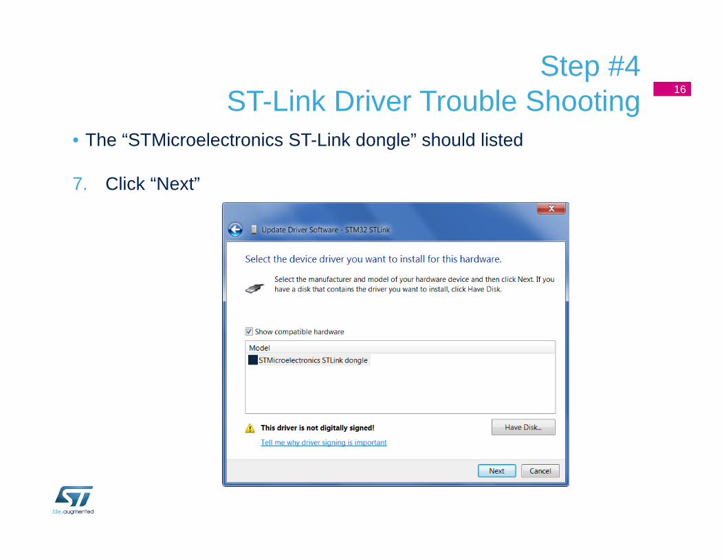
Step #4ST-Link Driver Trouble Shooting
• The “STMicroelectronics ST-Link dongle” should listed
7. Click “Next”
16

Step #4ST-Link Driver Trouble Shooting
• A warning message may appear
8. Select “Install this driver software anyway”
17

Step #4ST-Link Driver Trouble Shooting
• You should receive a message: “Windows has successfully updated your driver software”
18
• Re-check device manager to ensure STMicroelectronics ST-Link dongle is functioning normally

STM32 F3 RESOURCES

Documentation resources• All documentation can be found at www.st.com/stm32f3discovery
under the “Design support” tab and….• In the directory C:\STM32F3Discovery_Kit\Docs
• You will find:• STM32F30x Datasheet • STM32F30x Reference Manual (RM0316)• STM32F30x Cortex-M4 programming manual (PM0214)• STM32F3DISCOVERY peripheral firmware examples (AN4157)• Getting started with software and firmware environments for the
STM32F3DISCOVERY kit (UM1562)• STM32F3DISCOVERY kit data brief (DB1739)• STM32F3DISCOVERY kit user manual (UM1570)• Evaluation Product License Agreement
20

Documentation resources
• Main website page for the STM32 family• www.st.com/stm32
• For STM32F3• www.st.com/stm32f3
• You can find• Datasheets• Applications Notes• Errata• Technical Notes• Programming Manuals• Reference Manual• User Manuals• Firmware
21

Support resources
• Technically trained distributors• Distributors listed on CONTACTS page, www.st.com/contactus
22
• ST Public Forums:• Located on main
www.st.com page under Support tab – ST e2e Communities
• Submit technical questions to ST Online Support:
• Located on main www.st.com page under the Support tab – Online Support

Process check
• At this point the ST-Link V2 should be recognized by your system.
• LD1 and LD2 should be on ON (indicating the board is powered and ST-Link is functional).
• LD3 to LD10 will be flashing in a rotating pattern.
23
• Board Test:• Press the USER Button Once to Select Gyro Function
• LD6 & LD9 (Green) will light when the Discovery board is rotated along the Roll access.• LD4 & LD10 (Blue) will light when the Discovery board is rotated along the Pitch access.
• Press the USER Button a 2nd time to Select the Digital Compass Function.• LD3 thru LD10 will Flash randomly until the Discovery is rotated.• Rotate the Discovery board around the Yaw axis until LD4 (Blue) lights. LD4 will be pointing
to magnetic North. (The STLINK USB connector will be pointing to the South.)• Rotate the Discovery Board around the Pitch or Roll axis.
LD4
LD1 LD2

Hands-On Part I: Edit, Compile, Download, Debug, and Run

Step #4bChange the project folder attributes
• Right-click on the STM32F3-Discovery_FW_V1.1.0 folder and select Properties…
25
13/08/2013Presentation Title

Step #4b
• Unselect the attribute: Only lecture and then Accept
26
13/08/2013Presentation Title

Step #5Open FW demo project with Keil uVision
• Using explorer, go to the directory: C:\stm32f3discovery_fw\STM32F3-Discovery_FW_V1.0.0\Project\Demonstration\MDK-ARM
• Double-click on the Demo.uvproj file
27

Step #5 - Inside Keil uVision 28
Files Window
Project Window
Build Button
Debug Button

Step #5bChange the Options for Target ‘Demo’
• Select Project::Options for Target ‘Demo’
29
13/08/2013Presentation Title

Step #5b
• Select Debug. Click on the symbol
30
13/08/2013Presentation Title

Step #5b
• Select ST-Link Debugger
31
13/08/2013Presentation Title

• Click the Settings button
32
13/08/2013Presentation Title

Step #5b
• Change Port to SW
33
13/08/2013Presentation Title

Step #5b
• Click on Flash Download and then the Add button
34
13/08/2013Presentation Title

Step #5b
• Select STM32F3xx Flash and then click on the Add button
35
13/08/2013Presentation Title

Step #5b
• Click on Utilities. Click the Settings button and select ST-Link Debugger
36
13/08/2013Presentation Title

Step #5b
• Finally, click on OK
37
13/08/2013Presentation Title

Step #6 - Compile• Click on the Build button or Menu::Project::Build Target
38
Build Button
• The project should compile without errors

Step #6b - Download• Click on the Download Button
• The program is downloaded to the device’s flash memory.
39
13/08/2013Presentation Title

Step #7 - Debug• Click on the Start/Stop Debug Session button or Menu:
Start/Stop Debug Session
40
Debug Button
• You should receive a warning message. Click “OK”

Step #7: The MDK-ARM IDE Debugger 41
Files Window
Disassembly Window
Memory WindowsRegister WindowCommand Window
Program counter position

Step #8 - Run• Click on the Run button to start the program
42
Run Button
• Your STM32F3DISCOVERY board LD3 thru LD10 will be flashing in a rotating pattern.
• Note: LD2 (ST-Link Status) will be flashing because of the communication occurring between the STLINK/V2 and EWARM.

Step #8 - Run
• Mission Accomplished
• Please click on the Stopbutton.
• You code will stop anywhere within the program flow
• Click on the Debug button to exit from the debugger
43
Stop Button
Debug Button

Let’s make a change• Double-click to open the main.c file.
• Scroll down to line 117.
• Using MDK-ARM, What physical pin of the STM32F303 is LED3 connected to?
• Enter a number from 10 to 500 and place in the Delay(xxx) statement.
• Do the same thing with lines 121, 125, 129, 133, 137, 141, and 145.
• Compile, Debug, and Run
• Validate! Did it work?
• Stop debug and exit the debugger
44

Step #10 Let’s take a look and make a change
45

Step #11 How Large Is TheSTM32F3Discovery Demo Code?
• Select Project::Options for Target ‘Demo’…
46
13/08/2013Presentation Title

Step #11 How Large Is TheSTM32F3Discovery Demo Code?
• Select Listing. Then select Linker Listing. Finally click on the OK button.
47
13/08/2013Presentation Title

Step #11 How Large Is TheSTM32F3Discovery Demo Code?
• Click on Project Build, to re-link the project and generate the ‘Demo.map’.
• Edit the ‘Demo.map’ file.• How much STM32F3 FLASH is required?• How much STM32F3 SRAM is required?
48
13/08/2013Presentation Title

STM32F3-Discovery Demo Firmware Project Overview

Project Files• MDK-ARM
• startup_stm32f30x.s• System initialization, vector table, reset and branch to main()
(Unique for each 3rd party tool chain)
• STM32_USB-FS-Device_Driver• Contains ST FS USB library functions.
• ST,3F3-Discovery• Board specific functions
• STM32F30x_StdPeriph_Driver• Contains peripheral library functions
• User files• main.c (program entry point)• system_stm32f3xx.c (initial system configuration)• stm32f0xx_it.c (ISR’s)• usb_xxxx.c (USB interface, not used)
50
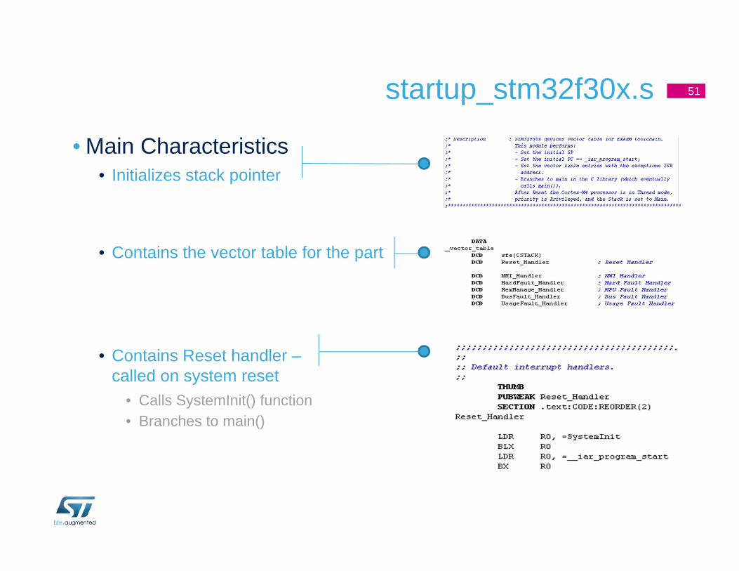
• Main Characteristics• Initializes stack pointer
• Contains the vector table for the part
• Contains Reset handler –called on system reset
• Calls SystemInit() function• Branches to main()
startup_stm32f30x.s 51

system_stm32f30x.c• SystemInit()
• This function is called at startup just after reset and before branch to main program. This call is made inside the "startup_stm32f3xx.s" file.
• Setups the system clock (System clock source, PLL Multiplier and Divider factors, AHB/APBxprescalers and Flash settings) STM32F3 Clock Configuration Tool
52
Define PLL source
SystemInit()...
Call SetSysClock()

main.c
• Example main() • Standard C main() function entry• Start of application program• What happens each time the USER
Button is pushed?• Goto Line 99, while(1)• Goto Line 112, LD3-LD10 Pattern• Goto Line 164, LD3-LD10 Gyro• Goto Line 232, LD3-LD10 Compass
53

stm32f30x_it.c
• Contains Cortex-M4 Processor Exception Handlers (ISRs)• void NMI_Handler(void);• void HardFault_Handler(void);• void SVC_Handler(void);• void PendSV_Handler(void);• void SysTick_Handler(void);
• Contains the STM32F30x Peripherals Interrupt Handlers (default is empty)
• Add the Interrupt Handler for the used peripheral(s) (PPP), for the available peripheral interrupt handler's name please refer to the startup file: startup_stm32f30x.s
• Go to Line 148: SysTick_Handler• What is SysTick ISR being used for?
• Go to Line 166: EXTI0_IRQHandler• What is the ISR use?• What physical pin of the STM32F3 is the ‘User Button’ connected to?
54

STM32F3-discovery.c
• Contains board specific function and definition
• Defines Push-button and LED GPIO definitions
• Contains board specific functions• void STM_EVAL_LEDInit(Led_TypeDef Led);• void STM_EVAL_LEDOn(Led_TypeDef Led);• void STM_EVAL_LEDOff(Led_TypeDef Led);• void STM_EVAL_LEDToggle(Led_TypeDef Led);• void STM_EVAL_PBInit(Button_TypeDef Button,
ButtonMode_TypeDef Button_Mode);• uint32_t STM_EVAL_PBGetState(Button_TypeDef Button);
55

stm32f30-discovery_l3gd20.cstm32f3-discovery_lsm303dlhc.c
• Each contains the driver information for the MEMs devices on STM32F3-Discovery Board.
• Each contains board specific functions
56

STM32F30x_StdPeriph_Driver
• Each file contains library functions that can be used for each peripheral and gives a standard API for access to peripheral functions.
• Browse to main.c, line 83, STM_EVAL_LEDInit(LED5), to investigate GPIO config.
• Browse to main.c, line 161, Demo_GyroConfig(), to investigate the Gryo config and the I2C config.
57

Thank you
www.st.com/stm32f3discovery