3-61 Analysis - - Get a Free Blog Here
22
3-24 3-61 The properties of compressed liquid water at a specified state are to be determined using the compressed liquid tables, and also by using the saturated liquid approximation, and the results are to be compared. Analysis Compressed liquid can be approximated as saturated liquid at the given temperature. Then from Table A-4, T = 100°C ⇒ error) (2.61% kJ/kg 419.17 error) (1.02% kJ/kg 6 0 . 419 error) (0.72% /kg m 0.001043 C 100 @ C 100 @ 3 C 100 @ = ≅ = ≅ = ≅ ° ° ° f f f h h u u v v From compressed liquid table (Table A-7), kJ/kg 430.39 kJ/kg 414.85 /kg m 0.001036 C 100 MPa 15 3 = = = ° = = h u T P v The percent errors involved in the saturated liquid approximation are listed above in parentheses. 3-62 EES Problem 3-61 is reconsidered. Using EES, the indicated properties of compressed liquid are to be determined, and they are to be compared to those obtained using the saturated liquid approximation. Analysis The problem is solved using EES, and the solution is given below. Fluid$='Steam_IAPWS' T = 100 [C] P = 15000 [kPa] v = VOLUME(Fluid$,T=T,P=P) u = INTENERGY(Fluid$,T=T,P=P) h = ENTHALPY(Fluid$,T=T,P=P) v_app = VOLUME(Fluid$,T=T,x=0) u_app = INTENERGY(Fluid$,T=T,x=0) h_app_1 = ENTHALPY(Fluid$,T=T,x=0) h_app_2 = ENTHALPY(Fluid$,T=T,x=0)+v_app*(P-pressure(Fluid$,T=T,x=0)) SOLUTION Fluid$='Steam_IAPWS' h=430.4 [kJ/kg] h_app_1=419.2 [kJ/kg] h_app_2=434.7 [kJ/kg] P=15000 [kPa] T=100 [C] u=414.9 [kJ/kg] u_app=419.1 [kJ/kg] v=0.001036 [m^3/kg] v_app=0.001043 [m^3/kg]
Transcript of 3-61 Analysis - - Get a Free Blog Here

3-24
3-61 The properties of compressed liquid water at a specified state are to be determined using the compressed liquid tables, and also by using the saturated liquid approximation, and the results are to be compared. Analysis Compressed liquid can be approximated as saturated liquid at the given temperature. Then from Table A-4,
T = 100°C ⇒
error) (2.61% kJ/kg 419.17error) (1.02%kJ/kg 60.419error) (0.72% /kgm 0.001043
C100@
C100@
3C100@
=≅=≅=≅
°
°
°
f
f
f
hhuuvv
From compressed liquid table (Table A-7),
kJ/kg 430.39kJ/kg 414.85
/kgm 0.001036
C100MPa 15
3
===
°==
huT
Pv
The percent errors involved in the saturated liquid approximation are listed above in parentheses. 3-62 EES Problem 3-61 is reconsidered. Using EES, the indicated properties of compressed liquid are to be determined, and they are to be compared to those obtained using the saturated liquid approximation. Analysis The problem is solved using EES, and the solution is given below. Fluid$='Steam_IAPWS' T = 100 [C] P = 15000 [kPa] v = VOLUME(Fluid$,T=T,P=P) u = INTENERGY(Fluid$,T=T,P=P) h = ENTHALPY(Fluid$,T=T,P=P) v_app = VOLUME(Fluid$,T=T,x=0) u_app = INTENERGY(Fluid$,T=T,x=0) h_app_1 = ENTHALPY(Fluid$,T=T,x=0) h_app_2 = ENTHALPY(Fluid$,T=T,x=0)+v_app*(P-pressure(Fluid$,T=T,x=0))
SOLUTION
Fluid$='Steam_IAPWS' h=430.4 [kJ/kg] h_app_1=419.2 [kJ/kg] h_app_2=434.7 [kJ/kg] P=15000 [kPa] T=100 [C] u=414.9 [kJ/kg] u_app=419.1 [kJ/kg] v=0.001036 [m^3/kg] v_app=0.001043 [m^3/kg]

3-25
3-63E A rigid tank contains saturated liquid-vapor mixture of R-134a. The quality and total mass of the refrigerant are to be determined. Analysis At 50 psia, vf = 0.01252 ft3/lbm and vg = 0.94791 ft3/lbm (Table A-12E). The volume occupied by the liquid and the vapor phases are
33 ft 12andft 3 == gf VV R-134a 15 ft3
50 psia Thus the mass of each phase is
lbm .6612/lbmft 0.94791
ft 12
lbm .63239/lbmft 0.01252
ft 3
3
3
3
3
===
===
g
gg
f
ff
m
m
v
V
v
V
Then the total mass and the quality of the refrigerant are mt = mf + mg = 239.63 + 12.66 = 252.29 lbm
0.05018===lbm 252.29
lbm 12.66
t
g
mm
x
3-64 Superheated steam in a piston-cylinder device is cooled at constant pressure until half of the mass condenses. The final temperature and the volume change are to be determined, and the process should be shown on a T-v diagram. Analysis (b) At the final state the cylinder contains saturated liquid-vapor mixture, and thus the final temperature must be the saturation temperature at the final pressure,
H2O 300°C 1 MPa
(Table A-5) C179.88°== MPa sat@1TT
(c) The quality at the final state is specified to be x2 = 0.5. The specific volumes at the initial and the final states are
(Table A-6) /kgm 0.25799C300
MPa 1.0 31
1
1 =
==
voTP
T1
2
/kgm .097750)001127.019436.0(5.0001127.0
5.0MPa 1.0
3
222
2
=−×+=
+=
==
fgf xxP
vvv
Thus, v 3m 20.128−=−=−= /kgm0.25799)5kg)(0.0977 (0.8)(∆ 3
12 vvV m

3-26
3-65 The water in a rigid tank is cooled until the vapor starts condensing. The initial pressure in the tank is to be determined. Analysis This is a constant volume process (v = V /m = constant), and the initial specific volume is equal to the final specific volume that is
(Table A-4) /kgm 48392.0 3C150@21 === °gvvv
°C
150
2501
2
Tsince the vapor starts condensing at 150°C. Then from Table A-6, H2O
T1= 250°CP1 = ?
T MPa 0.60=
=°=
131
1
/kgm 0.39248C025
Pv
v
3-66 Water is boiled in a pan by supplying electrical heat. The local atmospheric pressure is to be estimated. Assumptions 75 percent of electricity consumed by the heater is transferred to the water. Analysis The amount of heat transfer to the water during this period is kJ 2700s) 6030(kJ/s) 2)(75.0(timeelect =×== fEQ
The enthalpy of vaporization is determined from
kJ/kg 2269kg 1.19kJ 2700
boil===
mQh fg
Using the data by a trial-error approach in saturation table of water (Table A-5) or using EES as we did, the saturation pressure that corresponds to an enthalpy of vaporization value of 2269 kJ/kg is Psat = 85.4 kPa which is the local atmospheric pressure.

3-27
3-67 Heat is supplied to a rigid tank that contains water at a specified state. The volume of the tank, the final temperature and pressure, and the internal energy change of water are to be determined. Properties The saturated liquid properties of water at 200°C are: vf = 0.001157 m3/kg and uf = 850.46 kJ/kg (Table A-4). Analysis (a) The tank initially contains saturated liquid water and air. The volume occupied by water is
3311 m 001619.0/kg)m 001157.0kg)( 4.1( === vV m
which is the 25 percent of total volume. Then, the total volume is determined from
3m 0.006476== )001619.0(25.01
V
(b) Properties after the heat addition process are
kg/m 004626.0kg 1.4
m 0.006476 33
2 ===mV
v
kJ/kg 5.22011kg/m 004626.0
2
2
2
2
32
==
°=
==
uPT
xkPa 21,367
C371.3v (Table A-4 or A-5 or EES)
(c) The total internal energy change is determined from kJ 1892==−=∆ kJ/kg 850.46)-kg)(2201.5 4.1()( 12 uumU
3-68 Heat is lost from a piston-cylinder device that contains steam at a specified state. The initial temperature, the enthalpy change, and the final pressure and quality are to be determined. Analysis (a) The saturation temperature of steam at 3.5 MPa is [email protected] MPa = 242.6°C (Table A-5)
QSteam
3.5 MPa
Then, the initial temperature becomes T1 = 242.6+5 = 247.6°C
Also, (Table A-6) kJ/kg 1.2821C6.247
MPa 5.31
1
1 =
°==
hTP
(b) The properties of steam when the piston first hits the stops are
(Table A-5) /kgm 001235.0
kJ/kg 7.10490
MPa 5.33
2
2
2
12
==
===
v
hx
PP
Then, the enthalpy change of steam becomes kJ/kg -1771=−=−=∆ 2821.17.104912 hhh
(c) At the final state
(Table A-4 or EES) 0.0006
kPa 1555==
°===
3
3
3
323
C200/kgm 001235.0
xP
Tvv
The cylinder contains saturated liquid-vapor mixture with a small mass of vapor at the final state.

3-28
Ideal Gas 3-69C Propane (molar mass = 44.1 kg/kmol) poses a greater fire danger than methane (molar mass = 16 kg/kmol) since propane is heavier than air (molar mass = 29 kg/kmol), and it will settle near the floor. Methane, on the other hand, is lighter than air and thus it will rise and leak out. 3-70C A gas can be treated as an ideal gas when it is at a high temperature or low pressure relative to its critical temperature and pressure. 3-71C Ru is the universal gas constant that is the same for all gases whereas R is the specific gas constant that is different for different gases. These two are related to each other by R = Ru / M, where M is the molar mass of the gas. 3-72C Mass m is simply the amount of matter; molar mass M is the mass of one mole in grams or the mass of one kmol in kilograms. These two are related to each other by m = NM, where N is the number of moles. 3-73 A balloon is filled with helium gas. The mole number and the mass of helium in the balloon are to be determined. Assumptions At specified conditions, helium behaves as an ideal gas. Properties The universal gas constant is Ru = 8.314 kPa.m3/kmol.K. The molar mass of helium is 4.0 kg/kmol (Table A-1). Analysis The volume of the sphere is
333 m 113.1m) (334
34
=== ππ rV
He D = 6 m
20°C 200 kPa
Assuming ideal gas behavior, the mole numbers of He is determined from
kmol 9.28=⋅⋅
==K) K)(293/kmolmkPa (8.314
)m kPa)(113.1 (2003
3
TRPN
u
V
Then the mass of He can be determined from kg 37.15=== kg/kmol) kmol)(4.0 (9.28NMm

3-29
3-74 EES Problem 3-73 is to be reconsidered. The effect of the balloon diameter on the mass of helium contained in the balloon is to be determined for the pressures of (a) 100 kPa and (b) 200 kPa as the diameter varies from 5 m to 15 m. The mass of helium is to be plotted against the diameter for both cases. Analysis The problem is solved using EES, and the solution is given below. "Given Data" {D=6 [m]} {P=200 [kPa]} T=20 [C] P=200 [kPa] R_u=8.314 [kJ/kmol-K] "Solution" P*V=N*R_u*(T+273) V=4*pi*(D/2)^3/3 m=N*MOLARMASS(Helium)
D [m] m [kg] 5 21.51
6.111 39.27 7.222 64.82 8.333 99.57 9.444 145 10.56 202.4 11.67 273.2 12.78 359 13.89 461
15 580.7
5 7 9 11 13 150
100
200
300
400
500
600
D [m]
m[kg]
P=100 kPa
P=200 kPa

3-30
3-75 An automobile tire is inflated with air. The pressure rise of air in the tire when the tire is heated and the amount of air that must be bled off to reduce the temperature to the original value are to be determined. Assumptions 1 At specified conditions, air behaves as an ideal gas. 2 The volume of the tire remains constant. Properties The gas constant of air is R = 0.287 kPa.m3/kg.K (Table A-1). Analysis Initially, the absolute pressure in the tire is Tire
25°C kPa310100210atm1 =+=+= PPP g
Treating air as an ideal gas and assuming the volume of the tire to remain constant, the final pressure in the tire can be determined from
kPa 336kPa) (310K 298K 323
11
22
2
22
1
11 ===→= PTTP
TP
TP VV
Thus the pressure rise is ∆P P P= − = − =2 1 336 310 26 kPa
The amount of air that needs to be bled off to restore pressure to its original value is
kg 0.0070=−=−=∆
=⋅⋅
==
=⋅⋅
==
0.08360.0906
kg 0.0836K) K)(323/kgmkPa (0.287
)m kPa)(0.025 (310
kg 0.0906K) K)(298/kgmkPa (0.287
)m kPa)(0.025 (310
21
3
3
2
12
3
3
1
11
mmmRTPm
RTPm
V
V
3-76E An automobile tire is under inflated with air. The amount of air that needs to be added to the tire to raise its pressure to the recommended value is to be determined. Assumptions 1 At specified conditions, air behaves as an ideal gas. 2 The volume of the tire remains constant. Properties The gas constant of air is R = 0.3704 psia.ft3/lbm.R (Table A-1E). Analysis The initial and final absolute pressures in the tire are Tire
0.53 ft3 90°F
20 psig
P1 = Pg1 + Patm = 20 + 14.6 = 34.6 psia P2 = Pg2 + Patm = 30 + 14.6 = 44.6 psia Treating air as an ideal gas, the initial mass in the tire is
lbm 0.0900R) R)(550/lbmftpsia (0.3704
)ft psia)(0.53 (34.63
3
1
11 =
⋅⋅==
RTPm V
Noting that the temperature and the volume of the tire remain constant, the final mass in the tire becomes
lbm 0.1160R) R)(550/lbmftpsia (0.3704
)ft psia)(0.53 (44.63
3
2
22 =
⋅⋅==
RTPm V
Thus the amount of air that needs to be added is ∆m m m= − = − =2 1 0.1160 0.0900 0.0260 lbm

3-31
3-77 The pressure and temperature of oxygen gas in a storage tank are given. The mass of oxygen in the tank is to be determined. Assumptions At specified conditions, oxygen behaves as an ideal gas Properties The gas constant of oxygen is R = 0.2598 kPa.m3/kg.K (Table A-1).
Pg = 500 kPaAnalysis The absolute pressure of O2 is
O2 V = 2.5 m3 T = 28°C
P = Pg + Patm = 500 + 97 = 597 kPa Treating O2 as an ideal gas, the mass of O2 in tank is determined to be
kg 19.08=+⋅⋅
==K273)K)(28/kgmkPa (0.2598
)m kPa)(2.5 (5973
3
RTPm V
3-78E A rigid tank contains slightly pressurized air. The amount of air that needs to be added to the tank to raise its pressure and temperature to the recommended values is to be determined. Assumptions 1 At specified conditions, air behaves as an ideal gas. 2 The volume of the tank remains constant. Properties The gas constant of air is R = 0.3704 psia.ft3/lbm.R (Table A-1E). Analysis Treating air as an ideal gas, the initial volume and the final mass in the tank are determined to be
lbm 33.73
R) R)(550/lbmftpsia (0.3704)ft 3psia)(196. (35
ft 196.3psia 20
R) R)(530/lbmftpsia 4lbm)(0.370 (20
3
3
2
22
33
1
11
=⋅⋅
==
=⋅⋅
==
RTP
m
PRTm
V
V
Air, 20 lbm
20 psia 70°F Thus the amount of air added is
∆m m m= − = − =2 1 33.73 20.0 13.73 lbm
3-79 A rigid tank contains air at a specified state. The gage pressure of the gas in the tank is to be determined. Assumptions At specified conditions, air behaves as an ideal gas. Properties The gas constant of air is R = 0.287 kPa.m3/kg.K (Table A-1). Analysis Treating air as an ideal gas, the absolute pressure in the tank is determined from Pg
kPa 1069.1m 0.4
K) K)(298/kgmkPa kg)(0.287 (53
3=
⋅⋅==
VmRTP
Air 400 L 25°C Thus the gage pressure is
kPa 972.1=−=−= 971069.1atmPPPg

3-32
3-80 Two rigid tanks connected by a valve to each other contain air at specified conditions. The volume of the second tank and the final equilibrium pressure when the valve is opened are to be determined. Assumptions At specified conditions, air behaves as an ideal gas. Properties The gas constant of air is R = 0.287 kPa.m3/kg.K (Table A-1). Analysis Let's call the first and the second tanks A and B. Treating air as an ideal gas, the volume of the second tank and the mass of air in the first tank are determined to be
kg 5.846K) K)(298/kgmkPa (0.287
)m kPa)(1.0 (500
kPa 200
K) K)(308/kgmkPa kg)(0.287 (5
3
3
1
1
3
1
11
=⋅⋅
=
=
=⋅⋅
=
=
AA
BB
RTPm
PRTm
V
V 3m2.21
A B
Thus,
× Air
m=5 kg T=35°C
P=200 kPa
Air V=1 m3 T=25°C
P=500 kPa
kg 10.8465.05.846m 3.212.211.0 3
=+=+==+=+=
BA
BA
mmmVVV
Then the final equilibrium pressure becomes
kPa284.1 m 3.21
K) K)(293/kgmkPa kg)(0.287 (10.8463
32
2 =⋅⋅
==V
mRTP

3-33
Compressibility Factor 3-81C It represent the deviation from ideal gas behavior. The further away it is from 1, the more the gas deviates from ideal gas behavior. 3-82C All gases have the same compressibility factor Z at the same reduced temperature and pressure. 3-83C Reduced pressure is the pressure normalized with respect to the critical pressure; and reduced temperature is the temperature normalized with respect to the critical temperature. 3-84 The specific volume of steam is to be determined using the ideal gas relation, the compressibility chart, and the steam tables. The errors involved in the first two approaches are also to be determined. Properties The gas constant, the critical pressure, and the critical temperature of water are, from Table A-1, R = 0.4615 kPa·m3/kg·K, Tcr = 647.1 K, Pcr = 22.06 MPa Analysis (a) From the ideal gas equation of state,
error) (17.6%/kgm 0.03106 3=⋅⋅
==kPa) (10,000
K) K)(673/kgmkPa (0.4615 3
PRT
v
(b) From the compressibility chart (Fig. A-15),
H2O 10 MPa 400°C
84.01.04
K 647.1K 673
0.453MPa 22.06
MPa 10
=
===
===
Z
TTT
PPP
crR
crR
Thus,
error) (1.2%/kgm 0.02609 3=== /kg)m 3106(0.84)(0.0 3idealvv Z
(c) From the superheated steam table (Table A-6),
} /kgm 0.02644 3=°== v C400
MPa 10TP
3-34
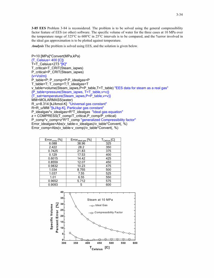
3-85 EES Problem 3-84 is reconsidered. The problem is to be solved using the general compressibility factor feature of EES (or other) software. The specific volume of water for the three cases at 10 MPa over the temperature range of 325°C to 600°C in 25°C intervals is to be compared, and the %error involved in the ideal gas approximation is to be plotted against temperature. Analysis The problem is solved using EES, and the solution is given below. P=10 [MPa]*Convert(MPa,kPa) {T_Celsius= 400 [C]} T=T_Celsius+273 "[K]" T_critical=T_CRIT(Steam_iapws) P_critical=P_CRIT(Steam_iapws) {v=Vol/m} P_table=P; P_comp=P;P_idealgas=P T_table=T; T_comp=T;T_idealgas=T v_table=volume(Steam_iapws,P=P_table,T=T_table) "EES data for steam as a real gas" {P_table=pressure(Steam_iapws, T=T_table,v=v)} {T_sat=temperature(Steam_iapws,P=P_table,v=v)} MM=MOLARMASS(water) R_u=8.314 [kJ/kmol-K] "Universal gas constant" R=R_u/MM "[kJ/kg-K], Particular gas constant" P_idealgas*v_idealgas=R*T_idealgas "Ideal gas equation" z = COMPRESS(T_comp/T_critical,P_comp/P_critical) P_comp*v_comp=z*R*T_comp "generalized Compressibility factor" Error_idealgas=Abs(v_table-v_idealgas)/v_table*Convert(, %) Error_comp=Abs(v_table-v_comp)/v_table*Convert(, %)
Errorcomp [%] Errorideal gas [%] TCelcius [C] 6.088 38.96 325 2.422 28.2 350
0.7425 21.83 375 0.129 17.53 400
0.6015 14.42 425 0.8559 12.07 450 0.9832 10.23 475 1.034 8.755 500 1.037 7.55 525 1.01 6.55 550
0.9652 5.712 575 0.9093 5 600
300 350 400 450 500 550 6000
5
10
15
20
25
30
35
40
TCelsius [C]
Per
cent
Err
or [
%]
Ideal GasIdeal Gas
Compressibility FactorCompressibility Factor
Steam at 10 MPa
Spe
cific
Vol
ume

3-35
3-86 The specific volume of R-134a is to be determined using the ideal gas relation, the compressibility chart, and the R-134a tables. The errors involved in the first two approaches are also to be determined. Properties The gas constant, the critical pressure, and the critical temperature of refrigerant-134a are, from Table A-1, R = 0.08149 kPa·m3/kg·K, Tcr = 374.2 K, Pcr = 4.059 MPa Analysis (a) From the ideal gas equation of state,
)(kPa 900
K) K)(343/kgmkPa (0.08149 3error 13.3%/kgm 0.03105 3=
⋅⋅==
PRT
v
(b) From the compressibility chart (Fig. A-15),
R-134a 0.9 MPa
70°C 894.0
.9170K 374.2
K 343
0.222MPa 4.059
MPa 0.9
=
===
===
Z
TTT
PPP
crR
crR
Thus,
error)(1.3%/kgm 0.02776 3=== /kg)m 03105(0.894)(0. 3idealvv Z
(c) From the superheated refrigerant table (Table A-13),
} /kgm 0.027413 3=°== vC07
MPa .90TP
3-87 The specific volume of nitrogen gas is to be determined using the ideal gas relation and the compressibility chart. The errors involved in these two approaches are also to be determined. Properties The gas constant, the critical pressure, and the critical temperature of nitrogen are, from Table A-1, R = 0.2968 kPa·m3/kg·K, Tcr = 126.2 K, Pcr = 3.39 MPa Analysis (a) From the ideal gas equation of state,
)error %4.86( kPa 10,000
K) K)(150/kgmkPa (0.2968 3/kgm0.004452 3=
⋅⋅==
PRT
v
(b) From the compressibility chart (Fig. A-15),
N2 10 MPa 150 K
54.01.19
K 126.2K 150
2.95MPa 3.39
MPa 10
=
===
===
Z
TTT
PPP
crR
crR
Thus,
error) (0.7% /kg)m 04452(0.54)(0.0 3ideal /kgm0.002404 3=== vv Z

3-36
3-88 The specific volume of steam is to be determined using the ideal gas relation, the compressibility chart, and the steam tables. The errors involved in the first two approaches are also to be determined. Properties The gas constant, the critical pressure, and the critical temperature of water are, from Table A-1, R = 0.4615 kPa·m3/kg·K, Tcr = 647.1 K, Pcr = 22.06 MPa Analysis (a) From the ideal gas equation of state,
error) (3.7%/kgm 0.09533 3=⋅⋅
==kPa 3500
K) K)(723/kgmkPa (0.4615 3
PRT
v
(b) From the compressibility chart (Fig. A-15), H2O
3.5 MPa 450°C 961.0
.121K 647.1
K 723
0.159MPa 22.06
MPa 3.5
=
===
===
Z
TTT
PPP
crR
crR
Thus,
error) (0.4%/kgm 0.09161 3=== /kg)m 09533(0.961)(0. 3idealvv Z
(c) From the superheated steam table (Table A-6),
} /kgm 0.09196 3=°== v C450
MPa .53TP
3-89E The temperature of R-134a is to be determined using the ideal gas relation, the compressibility chart, and the R-134a tables. Properties The gas constant, the critical pressure, and the critical temperature of refrigerant-134a are, from Table A-1E, R = 0.10517 psia·ft3/lbm·R, Tcr = 673.6 R, Pcr = 588.7 psia Analysis (a) From the ideal gas equation of state,
R527.2 R)/lbmftpsia (0.10517
/lbm)ft 86psia)(0.13 (4003
3=
⋅⋅==
RPT v
(b) From the compressibility chart (Fig. A-15a),
03.11.15
R) R)(673.65/lbmftpsia (0.10517psia) 7/lbm)(588.ft (0.1386
/
0.678psia 588.7
psia 400
3
3actual
=
=⋅⋅
==
===
R
crcrR
crR
T
PRT
PPP
vv
Thus, R 693.8=×== 6.67303.1crRTTT
(c) From the superheated refrigerant table (Table A-13E),
R) (700F240°=
== TP
/lbmft 0.13853psia 400
3v
3-37
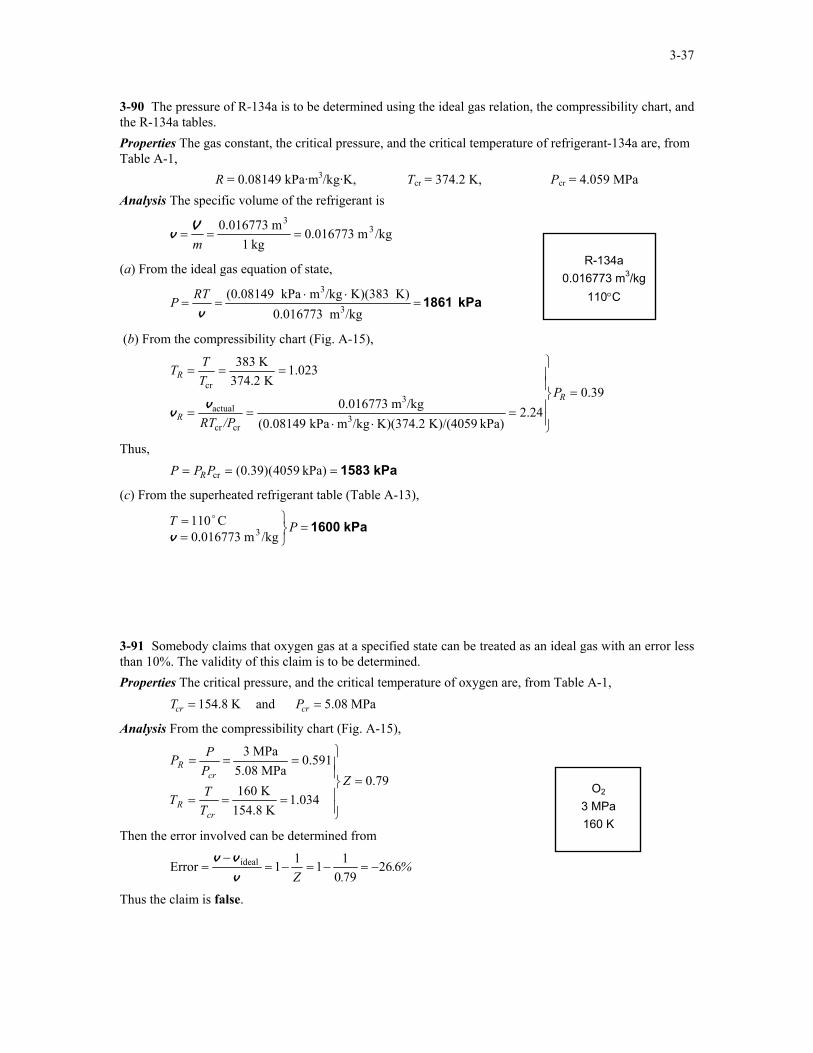
3-90 The pressure of R-134a is to be determined using the ideal gas relation, the compressibility chart, and the R-134a tables. Properties The gas constant, the critical pressure, and the critical temperature of refrigerant-134a are, from Table A-1, R = 0.08149 kPa·m3/kg·K, Tcr = 374.2 K, Pcr = 4.059 MPa Analysis The specific volume of the refrigerant is
/kgm 0.016773kg 1
m 0.016773 33===
mV
v
R-134a 0.016773 m3/kg
110°C
(a) From the ideal gas equation of state,
kPa 1861=⋅⋅
==/kgm 0.016773
K) K)(383/kgmkPa (0.081493
3
vRTP
(b) From the compressibility chart (Fig. A-15),
39.02.24
kPa) K)/(4059 K)(374.2/kgmkPa (0.08149/kgm 0.016773
1.023K 374.2
K 383
3
3
crcr
actual
cr=
=⋅⋅
==
===
R
R
R
P
/PRT
TTT
vv
Thus, kPa 1583=== kPa) 4059(0.39)(crPPP R
(c) From the superheated refrigerant table (Table A-13),
kPa 1600=
== PT
/kgm 0.016773C110
3v
o
3-91 Somebody claims that oxygen gas at a specified state can be treated as an ideal gas with an error less than 10%. The validity of this claim is to be determined. Properties The critical pressure, and the critical temperature of oxygen are, from Table A-1, T Pcr cr= =154.8 K and 5.08 MPa
Analysis From the compressibility chart (Fig. A-15),
79.01.034
K 154.8K 160
0.591MPa 5.08
MPa 3
=
===
===
Z
TTT
PPP
crR
crR
O2 3 MPa 160 K
Then the error involved can be determined from
%..Z
6267901111Error ideal −=−=−=
−=
v
vv
Thus the claim is false.

3-38
3-92 The percent error involved in treating CO2 at a specified state as an ideal gas is to be determined. Properties The critical pressure, and the critical temperature of CO2 are, from Table A-1, MPa7.39andK304.2 crcr == PT
Analysis From the compressibility chart (Fig. A-15),
80.00.93
K 304.2K 283
0.406MPa 7.39
MPa 3
cr
cr =
===
===
Z
TTT
PPP
R
R
CO2 3 MPa 10°C
Then the error involved in treating CO2 as an ideal gas is
25.0%or 0.250.80
1111Error ideal −=−=−=−
=Zv
vv
3-93 The % error involved in treating CO2 at a specified state as an ideal gas is to be determined. Properties The critical pressure, and the critical temperature of CO2 are, from Table A-1, MPa 7.39andK 304.2 crcr == PT
Analysis From the compressibility chart (Fig. A-15),
84.01.25
K 304.2K 380
0.947MPa 7.39
MPa 7
cr
cr =
===
===
Z
TTT
PPP
R
R
CO2
7 MPa 380 K
Then the error involved in treating CO2 as an ideal gas is
19.0% or 0.1900.84
1111Error ideal −=−=−=−
=Zv
vv

3-39
3-94 CO2 gas flows through a pipe. The volume flow rate and the density at the inlet and the volume flow rate at the exit of the pipe are to be determined.
450 K CO2 3 MPa 500 K 2 kg/s
Properties The gas constant, the critical pressure, and the critical temperature of CO2 are (Table A-1) R = 0.1889 kPa·m3/kg·K, Tcr = 304.2 K, Pcr = 7.39 MPa Analysis (a) From the ideal gas equation of state,
error) (2.1%/kgm 0.06297 3=⋅⋅
==kPa) (3000
K) K)(500/kgmkPa 89kg/s)(0.18 (2 3
1
11 P
RTm&&V
error) (2.1%mkg/ 31.76 3=⋅⋅
==K) K)(500/kgmkPa (0.1889
kPa) (30003
1
11 RT
Pρ
error) (3.6%/kgm 0.05667 3=⋅⋅
==kPa) (3000
K) K)(450/kgmkPa 89kg/s)(0.18 (2 3
2
22 P
RTm&&V
(b) From the compressibility chart (EES function for compressibility factor is used)
9791.01.64
K 304.2K 500
0.407MPa 7.39
MPa 3
11
1,
1
=
===
===
Z
TTT
PPP
crR
crR
9656.01.48
K 304.2K 450
0.407MPa 7.39
MPa 3
22
2,
2
=
===
===
Z
TTT
PPP
crR
crR
Thus, /kgm 0.06165 3=⋅⋅
==kPa) (3000
K) K)(500/kgmkPa 89kg/s)(0.18 (0.9791)(2 3
1
111 P
RTmZ &&V
3mkg/ 32.44=⋅⋅
==K) K)(500/kgmkPa .1889(0.9791)(0
kPa) (30003
11
11 RTZ
Pρ
/kgm 0.05472 3=⋅⋅
==kPa) (3000
K) K)(450/kgmkPa 89kg/s)(0.18 (0.9656)(2 3
2
222 P
RTmZ &&V

3-40
Other Equations of State 3-95C The constant a represents the increase in pressure as a result of intermolecular forces; the constant b represents the volume occupied by the molecules. They are determined from the requirement that the critical isotherm has an inflection point at the critical point. 3-96 The pressure of nitrogen in a tank at a specified state is to be determined using the ideal gas, van der Waals, and Beattie-Bridgeman equations. The error involved in each case is to be determined. Properties The gas constant, molar mass, critical pressure, and critical temperature of nitrogen are (Table A-1) R = 0.2968 kPa·m3/kg·K, M = 28.013 kg/kmol, Tcr = 126.2 K, Pcr = 3.39 MPa Analysis The specific volume of nitrogen is
N2 0.0327 m3/kg
175 K
/kgm 0.0327kg 100m 3.27 3
3===
mV
v
(a) From the ideal gas equation of state,
error) (5.5%kPa 1588=⋅⋅
==/kgm 0.0327
K) K)(175/kgmkPa (0.29683
3
vRTP
(b) The van der Waals constants for nitrogen are determined from
a
R TP
bRT
P
cr
cr
cr
cr
= =⋅ ⋅
= ⋅
= =⋅ ⋅×
=
2764
8
2 2 (27)(0.2968 kPa m / kg K) (126.2 K)(64)(3390 kPa)
0.175 m kPa / kg
(0.2968 kPa m / kg K)(126.2 K)8 3390 kPa
0.00138 m / kg
3 2 26 2
33
Then,
error) (0.7%kPa 1495=−−×
=−−
=22 (0.0327)
0.1750.001380.0327
1750.2968vva
bRTP
(c) The constants in the Beattie-Bridgeman equation are
/kmolKm104.2
0.050840.91600.0069110.050461
132.3390.9160
0.026171136.23151
334 ⋅×=
=
−−=
−=
=
−=
−=
c
bBB
aAA
o
o
v
v
since /kmolm 0.9160/kg)m .0327kg/kmol)(0 (28.013 33 === vv M . Substituting,
( )
( )( )
error) (0.07%kPa 1504=
−+
××
−×
=
−+
−=
23
4
2
232
0.9160132.3390.050840.9160
1750.9160104.21
(0.9160)5178.314
1v
vvv
ABTcTRP u

3-41
3-97 The temperature of steam in a tank at a specified state is to be determined using the ideal gas relation, van der Waals equation, and the steam tables. Properties The gas constant, critical pressure, and critical temperature of steam are (Table A-1) R = 0.4615 kPa·m3/kg·K, Tcr = 647.1 K, Pcr = 22.06 MPa Analysis The specific volume of steam is
/kgm 0.3520kg 2.841
m 1 33
===mV
v H2O 1 m3
2.841 kg 0.6 MPa
(a) From the ideal gas equation of state,
K457.6 K/kgmkPa 0.4615
/kg)m kPa)(0.352 (6003
3=
⋅⋅==
RPT v
(b) The van der Waals constants for steam are determined from
/kgm 0.00169kPa 22,0608
K) K)(647.1/kgmkPa (0.46158
kPa/kgm 1.705kPa) 0(64)(22,06
K) (647.1K)/kgmkPa 5(27)(0.46164
27
33
2622322
=×
⋅⋅==
⋅=⋅⋅
==
cr
cr
cr
cr
PRT
b
PTR
a
Then,
( ) ( ) K 465.9=−
+=−
+= 0.001690.352(0.3520)
1.7056000.4615
1122
baPR
T vv
(c) From the superheated steam table (Tables A-6),
K) 473( /kgm 00.352MPa 0.6
3 =°=
== C200TP
v

3-42
3-98 EES Problem 3-97 is reconsidered. The problem is to be solved using EES (or other) software. The temperature of water is to be compared for the three cases at constant specific volume over the pressure range of 0.1 MPa to 1 MPa in 0.1 MPa increments. The %error involved in the ideal gas approximation is to be plotted against pressure. Analysis The problem is solved using EES, and the solution is given below. Function vanderWaals(T,v,M,R_u,T_cr,P_cr) v_bar=v*M "Conversion from m^3/kg to m^3/kmol" "The constants for the van der Waals equation of state are given by equation 3-24" a=27*R_u^2*T_cr^2/(64*P_cr) b=R_u*T_cr/(8*P_cr) "The van der Waals equation of state gives the pressure as" vanderWaals:=R_u*T/(v_bar-b)-a/v_bar**2 End m=2.841[kg] Vol=1 [m^3] {P=6*convert(MPa,kPa)} T_cr=T_CRIT(Steam_iapws) P_cr=P_CRIT(Steam_iapws) v=Vol/m P_table=P; P_vdW=P;P_idealgas=P T_table=temperature(Steam_iapws,P=P_table,v=v) "EES data for steam as a real gas" {P_table=pressure(Steam_iapws, T=T_table,v=v)} {T_sat=temperature(Steam_iapws,P=P_table,v=v)} MM=MOLARMASS(water) R_u=8.314 [kJ/kmol-K] "Universal gas constant" R=R_u/MM "Particular gas constant" P_idealgas=R*T_idealgas/v "Ideal gas equation" "The value of P_vdW is found from van der Waals equation of state Function" P_vdW=vanderWaals(T_vdW,v,MM,R_u,T_cr,P_cr) Error_idealgas=Abs(T_table-T_idealgas)/T_table*Convert(, %) Error_vdW=Abs(T_table-T_vdW)/T_table*Convert(, %)
P [kPa] Tideal gas [K] Ttable [K] TvdW [K] Errorideal gas [K] 100 76.27 372.8 86.35 79.54 200 152.5 393.4 162.3 61.22 300 228.8 406.7 238.2 43.74 400 305.1 416.8 314.1 26.8 500 381.4 425 390 10.27 600 457.6 473 465.9 3.249 700 533.9 545.3 541.8 2.087 800 610.2 619.1 617.7 1.442 900 686.4 693.7 693.6 1.041
1000 762.7 768.6 769.5 0.7725

3-43
]
%
[
or
Err
100 200 300 400 500 600 700 800 900 10000
10
20
30
40
50
60
70
80
90
100
P [kPa]
vdW
van der WaalsIdeal gas
10-3 10-2 10-1 100 101 102 103200
300
400
500
600
700
800
900
1000
v [m3/kg]
T [K
]
600 kPa
0.05 0.1 0.2 0.5
T vs. v for Steam at 600 kPa
Steam Table
Ideal Gas
van der Waals
100 200 300 400 500 600 700 800 900 100050
100150200250300350400450500550600650700750800
P [kPa]
T tab
le [
K]
Steam tablevan der WaalsIdeal gas
10-3 10-2 10-1 100 101 102 103200
300
400
500
600
700
800
900
1000
v [m3/kg]
T [K
]
6000 kPa
T vs v for Steam at 6000 kPa
Steam Table
Ideal Gas
van der Waals
3-44
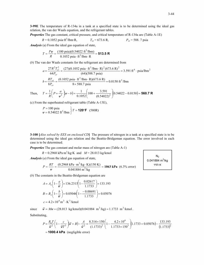
3-99E The temperature of R-134a in a tank at a specified state is to be determined using the ideal gas relation, the van der Waals equation, and the refrigerant tables. Properties The gas constant, critical pressure, and critical temperature of R-134a are (Table A-1E) R = 0.1052 psia·ft3/lbm·R, Tcr = 673.6 R, Pcr = 588. 7 psia Analysis (a) From the ideal gas equation of state,
R 513.5=⋅⋅
==R/lbmftpsia 0.1052
/lbm)ft 022psia)(0.54 (1003
3
RPT v
(b) The van der Waals constants for the refrigerant are determined from
/lbmft 0.0150psia 588.78
R) R)(673.6/lbmftpsia (0.10528
psia/lbmft 3.591psia) (64)(588.7
R) (673.6R)/lbmftpsia 2(27)(0.10564
27
33
2622322
=×
⋅⋅==
⋅=⋅⋅
==
cr
cr
cr
cr
PRT
b
PTR
a
Then, ( ) ( ) R 560.7=−
+=−
+= 0.01500.54022
(0.54022)3.591100
0.105211
22 baPR
T vv
(c) From the superheated refrigerant table (Table A-13E),
R)(580/lbmft 0.54022psia 100
3 F120°=
== TP
v
3-100 [Also solved by EES on enclosed CD] The pressure of nitrogen in a tank at a specified state is to be determined using the ideal gas relation and the Beattie-Bridgeman equation. The error involved in each case is to be determined. Properties The gas constant and molar mass of nitrogen are (Table A-1)
N2 0.041884 m3/kg
150 K
R = 0.2968 kPa·m3/kg·K and M = 28.013 kg/kmol Analysis (a) From the ideal gas equation of state,
)error .3%6( /kgm 0.041884
K) K)(150/kgmkPa (0.29683
3kPa1063=
⋅⋅==
vRTP
(b) The constants in the Beattie-Bridgeman equation are
/kmolKm104.2
0.050761.17330.0069110.050461
133.1931.17330.026171136.23151
334 ⋅×=
=
−−=
−=
=
−=
−=
c
bBB
aAA
o
o
v
v
since /kmolm 1.1733/kg)m .041884kg/kmol)(0 (28.013 33 === vv M .
Substituting,
( ) ( )
( )error) e(negligibl
1.1733133.1930.050761.1733
1501.1733104.21
(1.1733)1508.3141 23
4
2232
kPa 1000.4=
−+
××
−×
=−+
−=
vv
vv
ABTcTRP u
3-45
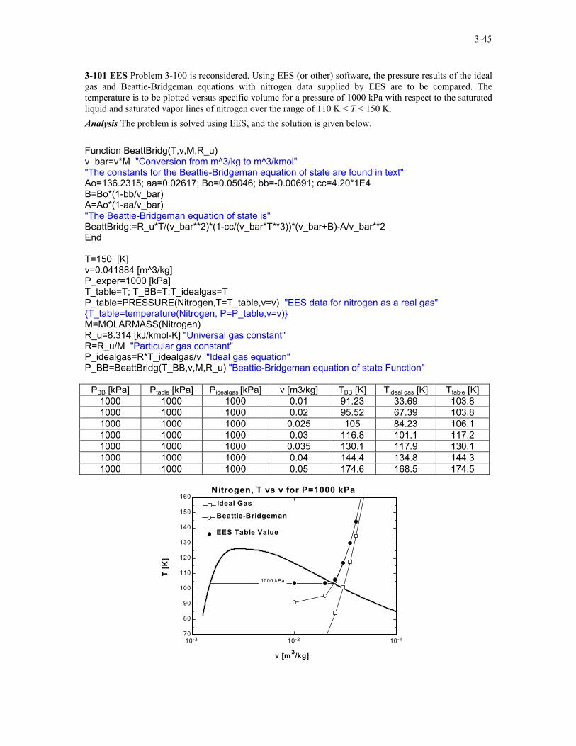
3-101 EES Problem 3-100 is reconsidered. Using EES (or other) software, the pressure results of the ideal gas and Beattie-Bridgeman equations with nitrogen data supplied by EES are to be compared. The temperature is to be plotted versus specific volume for a pressure of 1000 kPa with respect to the saturated liquid and saturated vapor lines of nitrogen over the range of 110 K < T < 150 K. Analysis The problem is solved using EES, and the solution is given below. Function BeattBridg(T,v,M,R_u) v_bar=v*M "Conversion from m^3/kg to m^3/kmol" "The constants for the Beattie-Bridgeman equation of state are found in text" Ao=136.2315; aa=0.02617; Bo=0.05046; bb=-0.00691; cc=4.20*1E4 B=Bo*(1-bb/v_bar) A=Ao*(1-aa/v_bar) "The Beattie-Bridgeman equation of state is" BeattBridg:=R_u*T/(v_bar**2)*(1-cc/(v_bar*T**3))*(v_bar+B)-A/v_bar**2 End T=150 [K] v=0.041884 [m^3/kg] P_exper=1000 [kPa] T_table=T; T_BB=T;T_idealgas=T P_table=PRESSURE(Nitrogen,T=T_table,v=v) "EES data for nitrogen as a real gas" {T_table=temperature(Nitrogen, P=P_table,v=v)} M=MOLARMASS(Nitrogen) R_u=8.314 [kJ/kmol-K] "Universal gas constant" R=R_u/M "Particular gas constant" P_idealgas=R*T_idealgas/v "Ideal gas equation" P_BB=BeattBridg(T_BB,v,M,R_u) "Beattie-Bridgeman equation of state Function"
PBB [kPa] Ptable [kPa] Pidealgas [kPa] v [m3/kg] TBB [K] Tideal gas [K] Ttable [K] 1000 1000 1000 0.01 91.23 33.69 103.8 1000 1000 1000 0.02 95.52 67.39 103.8 1000 1000 1000 0.025 105 84.23 106.1 1000 1000 1000 0.03 116.8 101.1 117.2 1000 1000 1000 0.035 130.1 117.9 130.1 1000 1000 1000 0.04 144.4 134.8 144.3 1000 1000 1000 0.05 174.6 168.5 174.5
10-3 10-2 10-170
80
90
100
110
120
130
140
150
160
v [m3/kg]
T [K
]
1000 kPa
Nitrogen, T vs v for P=1000 kPa
EES Table ValueEES Table Value
Beattie-BridgemanBeattie-Bridgeman
Ideal GasIdeal Gas