2:GENERAL OBJECTIVES IN FORMWORK BUILDINGimcyc.com/biblioteca/ArchivosPDF/Cimbras en...
13
2:GENERAL OBJECTIVES IN FORMWORK BUILDING FORE\IS ARE THE TOOLS and dies of concrete construction. They mold the concrete to the desired size and shape and control its position and alignment. But formwork is more than a mold; it is a temporary structure that supports its own weight and that of the freshly placed concrete as well as construction live loads including materials, equipment, and workmen. The form builder is concerned with more than simply making forms the right size; his objectives are three- fold : Qdit!/-to clcsisn rind build forms accurately so that the desired size, Aape, position, and finish of the cast con- crctc are attained. Safet!/-to build suhstantidly so that form\vork is capa- ble of supporting nil dent1 and live loads without collapse or danger to workmen and to the concrete structure. Econonl!/-to build efficiently, saving time and money for the contractor and owner alike. Economy is a major concern since formwork costs may range anywhere from 35 to 60 percent of the cost of the concrete structure. Savings depend on the ingenuity and experience of the contractor. Judgment in the selection of materials and equipment, in plan- ning fabrication and erection procedures, and in sched- uling reuse of forms, will expedite the job and cut costs. The architect or engineer can also do much to help save formwork cost by keeping the requirements of formwork economy in mind when he is designing the structure. In designing and building formwork, the contractor should aim for maximum economy without sacrificing quality or safety. Short-cuts in design or construction that endanger quality or safety may be false economy. If forms do not produce the specified surface finish, for example, much hand rubbing of the concrete may be required; or if forms deflect excessively, bulges in the concrete may require expensive chipping and grinding. Obviously economy measures that lead to formwork failure also defeat their own purpose. How Formwork Affects Concrete Quality Size, shape, and alignment of slabs, beams, and other concrete structural elements depend on accurate construction of the forms. The forms must be built to correct dimensions, must be sufficiently rigid under the construction loads to maintain the designed shape of the concrete, must be stable and strong enough to maintain large members in alignment, and must be substantially constructed so they can withstand han- dling and reuse without losing their dimensional in- tegrity. The formwork must remain in place until the concrete is strong enough to carry its own weight, or the finished structure may be damaged. The quality of surface finish of the concrete is af- fected by the material of the form. For example, if a patterned or textured finish is to be secured by use of a textured liner, the liner must be properly supported so that it will not deflect and cause indentations in the concrete surface. A correct combination of form materi- al and oil or other parting compound can contribute materially to eliminating air holes or other surface imperfections in the cast concrete. Causes of Failures Among the accidents and failures that occur during concrete construction, many are formwork failures, which usually happen at the time concrete is being placed. A system of formwork filled with wet con- crete has its weight at the top and is not basically a stable structure. Generally some unexpected event 2-1
Transcript of 2:GENERAL OBJECTIVES IN FORMWORK BUILDINGimcyc.com/biblioteca/ArchivosPDF/Cimbras en...

2:GENERAL OBJECTIVES INFORMWORK BUILDING
FORE\IS ARE THE TOOLS and dies of concreteconstruction. They mold the concrete to the desiredsize and shape and control its position and alignment.But formwork is more than a mold; it is a temporarystructure that supports its own weight and that of thefreshly placed concrete as well as construction liveloads including materials, equipment, and workmen.The form builder is concerned with more than simplymaking forms the right size; his objectives are three-fold :
Qdit!/-to clcsisn rind build forms accurately so that thedesired size, Aape, position, and finish of the cast con-
crctc are attained.
Safet!/-to build suhstantidly so that form\vork is capa-ble of supporting nil dent1 and live loads without collapse
or danger to workmen and to the concrete structure.
Econonl!/-to build efficiently, saving t ime and money
for the contractor and owner alike.
Economy is a major concern since formwork costsmay range anywhere from 35 to 60 percent of the costof the concrete structure. Savings depend on theingenuity and experience of the contractor. Judgmentin the selection of materials and equipment, in plan-ning fabrication and erection procedures, and in sched-uling reuse of forms, will expedite the job and cutcosts. The architect or engineer can also do much tohelp save formwork cost by keeping the requirementsof formwork economy in mind when he is designingthe structure.
In designing and building formwork, the contractorshould aim for maximum economy without sacrificingquality or safety. Short-cuts in design or constructionthat endanger quality or safety may be false economy.If forms do not produce the specified surface finish,for example, much hand rubbing of the concrete maybe required; or if forms deflect excessively, bulges inthe concrete may require expensive chipping andgrinding. Obviously economy measures that lead toformwork failure also defeat their own purpose.
How FormworkAffects ConcreteQuality
Size, shape, and alignment of slabs, beams, andother concrete structural elements depend on accurateconstruction of the forms. The forms must be built tocorrect dimensions, must be sufficiently rigid underthe construction loads to maintain the designed shapeof the concrete, must be stable and strong enough tomaintain large members in alignment, and must besubstantially constructed so they can withstand han-dling and reuse without losing their dimensional in-tegrity. The formwork must remain in place until theconcrete is strong enough to carry its own weight, orthe finished structure may be damaged.
The quality of surface finish of the concrete is af-fected by the material of the form. For example, if apatterned or textured finish is to be secured by use ofa textured liner, the liner must be properly supportedso that it will not deflect and cause indentations in theconcrete surface. A correct combination of form materi-al and oil or other parting compound can contributematerially to eliminating air holes or other surfaceimperfections in the cast concrete.
Causes of FailuresAmong the accidents and failures that occur during
concrete construction, many are formwork failures,which usually happen at the time concrete is beingplaced. A system of formwork filled with wet con-crete has its weight at the top and is not basically astable structure. Generally some unexpected event
2-1
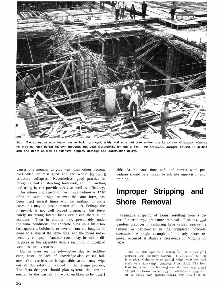
2-1 The contractor must know how to build formwork safely and must not take undue risks for the sake of economy; otherwise
he may not only defeat his own purposes, but bear responsibility for loss of life.
and one death as well as extensive property damage and construction delays.This formwork collapse caused 15 injuries
causes one member to give way, then others becomeoverloaded or misaligned and the whole formworkstructure collapses. Nevertheless, good practice indesigning and constructing formwork, and in handlingand using it, can provide safety as well as efficiency.
An interesting aspect of formwork failures is thatoften the same design, or even the same form, hasbeen uSed several times with no mishap. In somecases this may be just a matter of luck. Perhaps theformwork is not well braced diagonally, but fortu-nately no strong lateral loads occur and there is noaccident. Then in another bay, presumably underthe same conditions, the concrete piles up a little toofast against a bulkhead, or several concrete buggies allcome to a stop at the same time, and the forms unex-pectedly collapse. Another cause may be minor dif-ferences in the assembly details resulting in localizedweakness or overstress.
Human error on the job-whether due to indiffer-ence, haste, or lack of knowledge-also causes fail-ures. One careless or irresponsible action may wipeout all the safety introduced in the design process,The form designer should plan systems that can beerected by the least skilled workmen likely to be avail-
2-2
able. At the same time, safe and correct work pro-cedures should be enforced by job site supervision andtraining.
Improper Stripping andShore Removal
Premature stripping of forms, resulting from a de-sire for economy, premature removal of shores, a11 dcareless practices in reshoring have caused IILIIIICI’OUS
failures or deficiencies in the completed concretestructure. A tragic example of too-early shore re-moval occurred at Bailey’s Crossroads in Virginia in1972:
This flat plate apartment building hat1 26 storicls plr~s
penthouse and four-story basement; it mcasurctl 6Os:386ft in plan. Colunnrs were nornlal weight concrete, ant1
slabs were l ightweight concrctv, 8 in . th ick . The l iveload for which the huildillg was tlesiqd wx almut5 0 psf. C o l u m n la)out uxs csscntially t h e sanle f o rall 26 stories, with spacings ranging from alxnlt 20 to

G E N E R A L O B J E C T I V E S
Improp stripping and reshoring may also causesnggiilg of partialI\. cured cw~crctc and dc~velopmentof fine hairline cracks \\hich in later \-ears create aserious maintenance problcn~. Inadec~uate size andspacing of re.sl~0rc.s m;\v Icad to a formwork collapduring construction as \vell as to damage of the con-crrtc s t ructure . Proper practices to forestall daningcof this t\-lx are discwsed in Cliaptw 10 under strip-ping and reshoring I
Inadequate BracingThe forces that cause forms to fail are usnally not
simple cases of vertical overloading. Of course thisdoes occur at times, as n~hm an estra load of con-crete is tl~iinl~ed into an already filled awn o f asl:llj form. or there is a conwntration of cqnipment ormnterial on one section of a form. The more frequentca~~ses of fornin-ork failure, however, arc’ other effectsthat introdrlw lateral force components or induce dis-placement of supporting members.
Inadequate cross bracing and horizontal bracing ofshores is One of the factors most frequcntlv invol\.ed inforni\\ork awitlcnts. Irnwtigations of cases involvingthousands of dollars of damage show evidence thatthe damage could have been prevented or held to am i n o r amormt i f nnlv a few llm&wl d o l l a r s Iladbeen spent on diagonai bracing for the formwork sup-ports. Consider the t\vo cases that follow:
The main exhibition floor of the New York Coliscvn
collapsed when concrete was being placed. Forms forthe floor slal, \+wc supported on two tiers of shores.
2-2 Premature removal of shores supporting a S-day-old
slab led to the collapse of that slab, which triggered a
failure progressing through the entire building height.Fourteen workers died.

FORMWORK FOR CONCRETE
2-3 High shoring with a heavy
load at the top is vulnerable toeccentric or lateral loadings. Di-
agonal bracing improves the sta-
bility of such a structure, as do guysor struts to solid ground or com-
pleted structure.
Improper lateral bracing of the formwork was also
blamed for a roof form collapse in a Toronto subway.
The facing material of the roof slab form was Y-in. ply-wood in the shape of an arch, fa\trncd to wood stringers
and supported by a xries of built-up woocl tran<ver\e
frames. The fr,ume\ were supported on ndju\table \hores,
set on an intermediate slab, with a co1 re\pontling \et ofshores beneath the intermediate Jab. There ~‘25 no d i -
agonal bracing bctwccn the frames or bores, and theframes were not braced ,rg&nst longi tudinal movement .A bulkhead at one end of the section was braced against
longitiidinal movement hut, a\ the concrete was placed,the load against the bulkhead cnu~tl the bracing to de-flect, permitting movement of the bulkhead. Apparently
this movement caused some of the jnck shores to slip ortip and the whole form collapsed.
When a faihne occurs at one point, inadequatebracing may permit the collapse to extend to a largeportion of the structure and multiply the damage.For example, suppose a workman accidentally ramshis wheelbarrow into some vertical shores and dis-lodges a couple of them; this may set up a chain reac-tion that brings down the entire floor. One majorobjective of bracing is to prevent such a minor acci-dent or failure from becoming a disaster.
VibrationForms sometimes collapse when their supporting
shores or jacks are displaced by vibration caused bypassing traffic or the movement of men and equipmenton the formwork, or the effect of vibrating concrete
to consolidate it. In one case, forms for a roof deckwere supported on extensible jacks, without diagonalbracing. \\‘hile concrete was being placed, some ofthe shoring jacks were vibrated out of plumb by con-crete buggies running on duck boards, and the formcollapsed. In another case, a second-floor form sup-ported by two tiers of pipe shores 30 ft high, andbraced horizontally at mid-length, failed while con-crete was being vibrated. Although vibration was theinitial cause in these cases, it is evident that lack ofdiagonal bracing was the factor that permitted com-plete failure.
Unstable Soil UnderMudsills, ShoringNot Plumb
Formwork should be safe if it is adequately bracedand constructed so all loads are carried to solid groundthrough vertical members. But the shores must be setplumb and the ground must be able to carry the loadwithout settling. Shores and mudsills must not rest onfrozen ground; moisture and heat from the concretingoperations, or changing air temperatures, may thawthe soil and allow settlement that overloads or shiftsthe formwork. Site drainage must be adequate to pre-vent a washout of soil supporting the mudsills.

GENERAL OBJECT IVES
Inadequate Control ofConcrete Placement
The temperature and rate of vertical placement ofconcrete are factors influencing the development oflateral pressures that act on the forms. If tempera-ture drops during construction operations, rate of con-creting often has to be slowrd down to prevent abuildup of lateral pressure overloading the forms. Ifthis is not done, formwork failures may result.
Failure to regulate properly the rate and order ofplacing concrete on horizontal smfaccs or curved roofsmay produce unbalanced loadings and consequentfailures of formwork.
When Formwork IsNot at Fault
It is natural, when forms and slabs collapse duringconcreting, to assume that the formwork was at fault.This is not always true; the collapse of one four-storystructure was thought at first to be caused by form-support failure but later investigation showed that someof the exterior wall columns were not on the solid rockassumed in the design plans. A column settled, becameinoperative, and the slabs collapsed. In other reportedcases slabs collapsed due to weakness caused by duct
openings at high-stress points, or failure to provideproper shear reinforcement. When lower floors collapsethey carry upper floor forms with them, and the situa-tion sometimes looks like a formwork failure until ananalytical investigation is made.
\\‘cll designed and strongly constructed formworkcan withstand some unusual loads. \Vhen a craneboom collal~scd during the casting of an upper floorof a concrctr apartment building in New York City(1959), tile boom fell across the working deck and\vrapped itself over both sides of the building. De-spite the impact of the falling boom, the forms andsupporting shorts were undamaged, and concretingoperations were resumed 2 days later after someminor repairs.
Lack of Attention toFormwork Details
failure, This may be as simple as insufficient nailing,or failure to tighten the locking devices on metalshoring. Other details which have caused failures areinadequate provisions to prevent rotation of beamforms \vhere slabs frame into them on one side; in-adeclunte anchorage against uplift for sloping formfaces; or lack of bracing or tying of corners, bulk-heads, and other places where unequal pressure isfound.
Planning for SafetySafety begins in the planning and mnnagemeut of a
project, and all bids should include allowance for thecost of supervision, equipment, and procedures thatwill assure safety for workmen and structure. Goodsafety planning is good profit planning because it getswork done in a controlled and supervised, rather thanhaphazard, manner.
To make sure forms are correctly designed andstrong enough for the expected load, rational analysisrather than rule of thumb is necessary. In the UnitedStates, formwork designers, project planners, andmanagers are subject to certain local code require-ments for formwork as well as to Occupational Safetyand Health Administration (OSHA) regulations andmust take these requirements into consideration as jobplanning proceeds.
The federal Occupational Safety and Ilealth Act in-cludes requirements for concrete, concrete forms, andshoring in Subpart Q of the Construction Safety and
2-4 Formwork collapsed at New York Coliseum where
rapid delivery with power buggies introduced lateral forcesat the top of high shoring.
Even when the b,lsic formwork design is soundlyconcci\cd, sm,111 diffcrc,nces in assembly details maycause local weakness or overstress leading to form
2-5

FORMWORK FOR CONCRETE
Health Regulations. 2-1 The long-awaited revision ofSubpart Q, which took effect in 1988, is reproduced inits entirety in the appendix of this book. In general it ismore performance oriented than the original 1971 reg-ulation.
In a nonmandatory appendix, Subpart Q states thatformwork in accordance with Sections 6 and 7 of theAmerican National Standard for Construction and Dem-olition Operations-Concrete and Masonry Work, ANSIA10.9-1983 2-2 will be deemed to meet OSHA’s generalrequirements for formwork. In a mandatory appendix,requirements for lift slab operations are referenced to anearlier document, ANSI A10.9-1970.
In another nonmandatory appendix, this book (AC1SP-4), AC1 347-78, 2-u and AC1 318-83 ‘-’ are includedamong information sources described as helpful in un-derstanding and complying with the requirements ofSubpart Q. AC1 347-78 has been superseded by AC1347R-88 “Guide for Concrete Formwork” 2-s (reprintedin full in the appendix). The text of this edition of SP-4emphasizes implementation of the AC1 347R-88 recom-mendations as one of the best means of achieving OSHAobjectives of safety in the reahn of forrnwork construc-tion. In addition, due consideration to local require-ments must be given on each job. At least 25 states havetheir own OSHA-approved occupational safety andhealth plans.
Many local and model building codes have adoptedAC1 318 “Ruilcling Code Requirements for ReinforcedConcrete” to cover concrete construction. For conve-nient reference Chapter 6 of AC1 318-89 2-7 is repro-duced in the appendix along with pertinent sections ofits commentary.
Supervision andInspection
The most effective means of achieving 5atcty in theuse of forms is to have comprtcnt srlpcr\ i\ion duringerection and concreting. Supervisors must see thatformwork is constructed exactly as designed, follow-ing a safe erection procedure so that no members aretemporarily overloaded. A form designer should beconsulted whenever a field change seems c&d forin the falsework or forms or in the erc,ction procrclure.
If forms have been designed with no anticipation ofunusual construction loads or ccccntric loads dnc to
placing sequence, the job superintendent must m,lkesure no such loads ever are imposed on the form\vork.He must be instructed as to the mauimum rate of riseof concrete for which vertical forms have b(len do-signed and rnu,t nu~kc ,mre tlris rutc is uot csczetlc~l.Formwork drawings prepared for field use shouldgive the superintendent full inform,ltion on thesefactors.
Platforms and Accessfor Workers
Sound engineering in the planning stage by cngi-neers working with rspc~ricncccl field p(‘rsormel candevelop safety measures for the protection of every-
2-5 Increased diagonal bracing was added to all remaining shoring for the New York Coliseum following partial col-
lapse of formwork.

one on the job. Any high construction job requires amethod of access and a work area or work platform.Long ladders to the tops of piers or falsework shouldhave rest or passing platforms that will also serve to
stop a serious fall. In some types of structures, partic-ularly bridges, it is necessary to provide special scaf-folds or equipment for stripping drck and pier forms.Safety signs and barricades should be erected to keepunauthoriTcd personnel clear of areas in which erec-tion or stripping is underway. Special requirementcfor scaffolds are given in ANSI A10.8. 2-8
Control of ConcretingPractices
Hate and sequence of concrete placing should fol-low any limitations shown on the formwork drawings.Concrete should not be placed until formwork for agiven section is completed. In addition, an attemptshould lx made to placc~ concrete so that unbalancedform loadings are avoided; for example, in beam andslab construction, fill the beams first and then workoutnarcl qu;dlv on both siclcs in placing thcl slab.
Improved st:ibility can 1~ obtained i n a colrlmn-and-slab structure by concreting the columns at lcnsta day ah~nd o f t h e clcck. II;~rd~~n~~l cLolrcrrtc> in thrcolmnns adds stiffhcss to the fornnvorl; striictiirc‘ tliir-
ing concrc,ting o f the sl31).L Job spcificatiolls frrx-clucntly rccluirc ad\ancc~ ciisting of colunms so tha tt h c v c a n tnkc their sllrinl;agc> l~f’ol-c, tlrc fioor i sphi&d. Any cstru cost occnsioncd 1)~ this proccdllrcmav be offset by the casicr casting o f the colllll7nSbefbrc the rc%forcing bars for the slal) arc set.
Form watchers must always be on the job duringconcreting whether or not there is danger to person-nel or to the structure from forms failing or distortingduring placement. Extra shores or other matcriaiand equipment that might be needed in an emergcnc)must be available.
Improving SoilBearing and Bracing
If there is doul,t about the lx%rin~ quality of thesoil, it can be compacted, stabilized by tamping in alean portland cement mortar, or covered with a layerof crushed stone. There is a limit to the unusual prob-lems that can be guarded against, bnt if formwork and
2-6 Stair tower with seven landings for access to highoff-rock wall forming. Scaffold with safety railings is attachedto forms. Safety regulations now call for toe boards onscaffolds such as these.
shorts arc asscmblcd in a strong, stable structure,th(,rc‘ is 1~s chance for complete failure under eventhe most severe conditions. If shores rest on sub-stantial mudsills and are diagonally braced in twodirections, an cnrth slippage or \\~ashout might causeshifting or sagging, but thcrc is less chance of a fullcollapse:. Jllst how far to go in guarding against the“unc~xpc~ctcd” is a matter of over-all economics, esperi-encc. and local conditions. Hut, at the \cry mini-inim. the ol)jccti\T slioulcl 1~ to so construct the formthat locaiizccl fnilulcs or accidents will not trigger acomplete and disastrons collapse.
Shoring and Reshoring\Vorkers should be instructed to install shores plumb
and lvcdgcd securely so that each carries its share ofthe load. A bent jack or defective timber may he ableto support only a fraction of the design load andshould not be used. \\‘hen concrete is placed in onesection of a form, it may calisc upwarcl movement inanother section. Shores then may come loose or shift
2-7
FORMWORK FOR CONCRETE
out of plumb unless they have been securely fastened.Alert, continuous form watching during concretingshould be routine practice so that problems like thesecan be met as soon as they arise.
The contractor should keep forms and shores inplace long enough to develop sufficient concretestrength to prevent hairline cracks or failures in theconcrete. He will be guided by OSHA requirements,local codes, job specifications, and engineer-architectapprovals where specified. In some cases, whrnforms are stripped for reuse, reshores are installed tosupport thr concrete umtil it attains full strength,Such reshoring must be done very carefully, and forc-men should understand that reshores must not bewedged in so tightly as to cause a stress reversal thatmight crack the concrete.recommendations.)
(See p. lo-18 for reshoring
tion to the obvious structural dimensions, such pointsas the following may be needed:
Inserts , waterdops. built-in frames for Openings, holes
through concrete, and similar requirements where workof otller trades will be at tached to or supported byformwork.
Concrete snrfilce finicht3 described in mensurable terms.Tolerances for plumb, level, size, thickness, and loca-tion.
Number, locdion, and &tnils Of all construction joints,contraction joints, mid rspansion joints,
Live load used in design of the structure.
Locations and dctds of architectural concrete.
Chamfer\ if required, or if prohibited, on beam soffitsor column corners.
Basic geometry of special structural shapes \uch as free-form shells.
Camber if required for slab soffits or structural members.
Special provisions for load transfer tlrning tensioning of
post-tensioned members, i f required.
Architect, Engineer
and Contractor
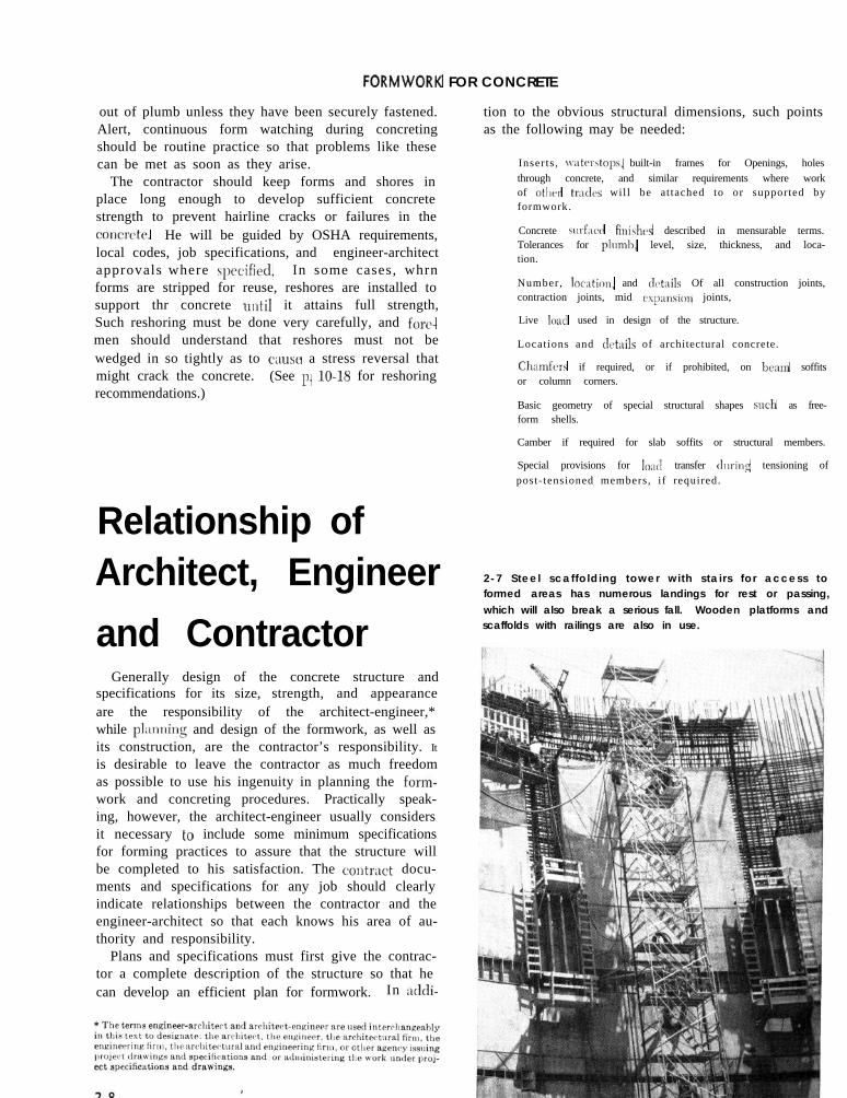
Relationship of2-7 Steel scaffolding tower with stairs for access toformed areas has numerous landings for rest or passing,
which will also break a serious fall. Wooden platforms andscaffolds with railings are also in use.
Generally design of the concrete structure andspecifications for its size, strength, and appearanceare the responsibility of the architect-engineer,*while plxrning and design of the formwork, as well asits construction, are the contractor’s responsibility. It
is desirable to leave the contractor as much freedomas possible to use his ingenuity in planning the form-work and concreting procedures. Practically speak-ing, however, the architect-engineer usually considersit necessary to include some minimum specificationsfor forming practices to assure that the structure willbe completed to his satisfaction. The contrxt docu-ments and specifications for any job should clearlyindicate relationships between the contractor and theengineer-architect so that each knows his area of au-thority and responsibility.
Plans and specifications must first give the contrac-tor a complete description of the structure so that hecan develop an efficient plan for formwork. In acldi-

GENERAL OBJECT IVES
If camber is desired for slab soffits or structuralmembers to compensate for elastic deflection and/ordeflection due to creep of the concrete, the contractdrawings must so indicate and state the amounts.Measurement of camber attained should be madeafter initial set and before decentering.
\Vhere architectural features, embedded items, orthe work of other trades will change the location ofstructural members such as joists in one-way or two-way joist systems, such changes or conditions shouldbe indicated on the structural drawings.
In addition to this full description of the requiredstructure, criteria for and some details of the formingpractices will be specified, depending in part on thetype of structure being erected. General minimumrequirements should be stated to assure the ownerand his architect or engineer that the formwork willprovide adequate support during concreting and untilthe concrete has gained sufficient strength to permitform removal. The following items should be clearlycovered in the engineer-architect specifications anddrawings: (a) by whom the formwork will be de-signed; ( 1,) bv whom, when, and for what featuresformnork will-be inspected; and (c) what approvalswill be rcciuired for formwork drawings; for the formsbefore concreting and during concreting; and forform removal and reshoring; and who will give suchapprovals.
Among the details of forming and constructionpractices that may have to be specified are the follow-ing :
Location and order of erection and removal of shoringfor composite construction, complex structures, and per-manent forms.
Stripping time (in terms of strength of field-cured con-crete) and reshoring requirements; decentering sequencefor shells and other complex structures.
Formwork materials and accessories where these arecritical to appearance or qualitv of finished structure.Sequence of concrete placement for structures where thisis critical.
Maintaining and Co-ordinating Tolerances
As mentioned earlier, the engineer-architect shouldspecify tolerances for the structure so the contractor willknow what is required and can design and maintain hisforms accordingly. Most of the tolerances for structuralmembers suggested in this book are taken from thespecification of AC1 Committee 117.* The toleranceamounts are similar to those specified on important workor major structures by many public agencies and private
firms. The designer who specifies these tolerances orsome modification of them should remember that spec-ifying any tolerances more exacting than needed mayincrease construction costs or delay the work withoutgood reason. ,
Contractors should establish and maintain in anundisturbed condition until final completion and ac-ceptance of a project, control points and bench marksadequate for their own use and for reference to estab-lish tolerances. (This requirement may be importantfor the contractor’s protection when tolerances are notspecified or shown. ) The engineer-architect shouldspecify tolerances or require performance within gen-erally accepted limits. Where a project involves par-ticular features sensitive to the cumulative effect ofgenerally accepted tolerances on individual portions,the engineer-architect should anticipate and providefor this effect by setting a cumulative tolerance.Where several types of generally accepted tolerances,i.e., on form, on location of reinforcement, on fabrica-tion of reinforcement, etc., may become mutually in-compatible, the engineer-architect should anticipatethe difficulty and specify special tolerances or indicatewhich controls. (See discussion of tolerances forplacing reinforcement, p. 10-4.)
The engineer-architect should be responsible forcoordinating the tolerances for concrete work with therequirements of other trades whose work adjoins theconcrete construction.
Preparing a FormworkSpecification
AC1 Committee 347 has emphasized that the form-work specification will have much to do with theover-all economy and quality of finished work. Sucha specification must be tailored to the particular job,must indicate to the contractor exactly what will beexpected from him, and must be so written as toresult in economy and safety.
A well-written formwork specification tends toequalize bids for the work, provided each bidderknows that full compliance will be required. Un-necessarily exacting requirements may make biddersquestion the specification as a whole and may renderit virtually impossible for them to be sure just what isexpected. They may be overly cautious and overbidor not cautious enough and underbid.
*AC1 Committee 117, “Proposed Standard Specifications for Tolerances forConcrete Construction and Materials (AC1 117);’ AC1 Materials Journal,Nov.-Dec. 1988, pp. 560-571.
2-9

FORMWORK FOR CONCRETE
A well-prepared formwork specification is of valuenot only to the owner and the contractor, but also tothe field superintendent of the engineer-architect andto the subcontractors for other trades.
“Specifications for Structural Concrete for Build-ings, ” prepared by AC1 Committee 301,“” includesprovisions for formwork and is set up as a referencespecification which the engineer-architect may makeapplicable to any building project by citing it in theproject specifications. If this document is used tocover basic formwork specifications, the architect-engineer must supplement by designating or specify-ing individual project requirements.
Design, Inspection, andApproval of Formwork
In most cases the contractor will plan and designthe formwork. Except for unusual or complex struc-tures, this is desirable since the contractor is in thebest position to evaluate men, materials, equipment,and procedures and arrive at a design that is bothstructurally sound and adapted to efficient erectionand concreting.
Although formwork safety is the responsibility ofthe contractor, the engineer or architect may requirethat the form design be subject to his review and/orapproval. Architect-engineer approval should be re-quired for unusually complicated structures, for struc-tures whose designs were predicated on a particularmethod of construction, for certain post-tensionedstructures, and for structures in which the forms im-part a desired architectural finish.
The committee has also called attention to the legalimplications of specifying in any set of contract docu-ments, including the plans and specifications, both themethod by which the work is to be performed and theresults to be accomplished. If the method is specifiedin detail, then provisions regarding the final resultsmay not be legally binding.
Complex StructuresIn the case of structures such as shells, arches, or
folded plates, with the complexity of designing form-work and planning erection and stripping proceduresnecessary to guarantee the desired shape, dimensions,and appearance of the concrete, it may be morepractical for the engineer or architect who designedthe structure to take responsibility for formwork de-sign. If the contractor assumes responsibility for de-sign of formwork for folded plates, thin shells, long
span roof structures, and similar space structures pre-senting complex three-dimensional problems in form-work design, his formwork planners should consultand cooperate with the architect-engineer to makesure the finished concrete will conform to his design.The contractor should receive written approval ofsuch formwork drawings from the architect-engineer.
Permanent FormsWhere metal deck or other material used as a
permanent form is also to have permanent structuralvalue, its shape, depth, gage, dimensions, and proper-ties as well as shoring requirements are to be indi-cated by the architect-engineer in the contract draw-ings and specifications. The contractor, nevertheless,may be asked to submit fully detailed shop drawingsof all permanent deck forms to the architect-engineerfor approval.
Shoring needs for this type of construction are fre-quently overlooked or misunderstood, and objcction-able deflection results. The alert contractor willeither provide for shoring in his bid, or obtain posi-tive assurance that it is not needed.
Composite ConstructionThe engineer or architect should specify shoring for
composite beam and slab construction wherever thedesign for composite action requires it. Committee 347recommends that the forms and supports be removedonly after tests and specified curing operations satisfy theengineer-architect that the most recently cast concretehas attained the strength required for composite action.The procedure for shore removal should also be speci-fied or reviewed by the engineer-architect in such cases.
Stripping and DecenteringFormwork must remain in place long enough to
make sure the concrete is self-supporting and stiffenough to carry its own weight and construction loadswithout undue deflection or damage. This is espe-cially important for long span members in flesure. ’To achieve the necessary strength, either the folmswill be left in place for a specified period of time,particularly on small projects where tests are notpracticable or where form reuse is not planned; or,preferably for all important projects, the time of re-moval will be determined by strength of test speci-mens. In the former case, the architect-engineer willinclude curing-time requirements in the specificationsor refer to applicable codes. If form removal is to bebased on strength tests, the architect-engineer shouldinclude instructions for the preparation and curing of
Z-10

GENERAL OBJECT IVES
test specimens in the specifications and should super-vise the testing and determine when it is safe toremove the forms.
In the case of the more complex structures such asshells, arches, and folded plates, to make sure thestructure will assume its deflected shape without dam-age, the decentering and handling procedure for theformwork should be worked out carefully. These pro-cedures should be described in the contract drawingsand specifications or, if worked out by the contractor,
*should be shown on the formwork drawings and ap-proved by the architect-engineer.
Materials and AccessoriesRelated to Finish ofExposed Concrete
If the particular design or desired finish requiresspecial materials, the engineer or architect should in-dicate in his contract plans and specifications whichformwork materials, ties, and other items are required.If internal ties are not acceptable, this should beclearly stated. In the interest of scheduling and econ-omy, the contractor should be permitted to use discre-tion where quality of finished concrete would not beimpaired by using alternate materials and methods.
Finish requirements for concrete surfaces should beprecisely described in measurable terms. This may
be done by limiting size and number of surface de-fects. Since some aspects of surface finish such as
Pay ForThese Areas
rzlm
Do NoFor
ulkhead
2 - 8 Suggested basis of measurement of form area forpayment purposes: Pay for all formed areas including
bulkheads; include area of recesses formed, but deductareas of openings larger than 30 sq ft on one contact
surface. Include formed grooves, keyways, etc., when theyare more than 3 in. deep and 6 in. wide.
texture, color, and uniformity are difficult to measure,agreement on finish requirements may more readilybe reached by having the contractor submit for ap-proval a sample panel prepared using the proposedform materials and form surface treatments. Thispanel would then remain on the job as a visual stand-ard of the required finish.
Measurement andPayment forFormwork
Payment for concrete formwork may be by any oneof three methods:
1. It may be included in the lump sum price for the en-tire job.2. It may be included in the unit price paid per cubicyard of concrete in place.3. A separate unit price per square foot of formed area isestablished.
Regardless of the contractual basis of payment, mostcontractors keep separate records of formwork cost,particularly for their larger jobs. This serves the dualpurpose of maintaining closer control on formworkcosts during the job, and also accumulating cost ex-perience data which could be valuable for negotiatingany extra work or in bidding future jobs.
When formwork is paid for at a separate unit price,the specifications should clearly state what areas of theformwork, if any, are excluded as pay areas. Somespecifications exclude openings such as doors, win-dows, and pipe blockouts from the area of formworkto be paid for. This represents a problem for the con-tractor who usually will have to build his form panelcontinuous across the opening and then attach formsfor the opening. Other specifications exclude onlyopenings in excess of a designated size such as 30 sqft. This latter practice permits normal door openingsto be paid for when door bucks are nailed to the mainform panels.
Some specifications exclude payment for bulkheadareas; this places the contractor at a disadvantage fortwo reasons :
Construction joint layout is subject to the owner’s ap-proval, and at the bidding stage the contractor cannotalways be sure of the owner’s intent on joint location.
The pay basis for formed area is usually used for pricingextra work which may have a ratio of bulkhead area toformed area that is substantially different from the mainjob .
2-11
FORMWORK FOR CONCRETE
If the contract specifications exclude payment forbulkheads, then they should be fully supported bycomprehensive construction joint drawings.
Contracts which specify payment for all formedareas in actual contact with concrete surfaces mayprove cumbersome to administer if the structure hasnumerous keyways, recesses, chamfers, or moldings.A less exacting method of measurement can beachieved by excluding such items when they areeither 3 in. or less in depth or 6 in. or less in width.
Where some formed surfaces are likely to be sub-stantially more expensive than others, and their ratioto the total form area is likely to vary during the job,separate pay rates for the two or more classes of form-work should be established.
How theArchitect-EngineerCan Reduce Formcosts
With formwork costs ranging up to 60 percent of thetotal cost of concrete work in a project, the architectand engineer can make big savings possible by con-sidcring problems of formwork economy at the sametime they design the concrete structure. The mainobjectives are to obtain maximum reuse of forms andto permit use of standard material sizes with minimumcutting and fitting. Planning a structure that usessimplified ornamentation and surfaces as formed, orwith a minimum of finishing, may also yield substan-tial savings. Frequent changes of dimensions of struc-tural members should be avoided; irregularities ofstructure intended to save concrete may be expensiverather than economical if they require intricate formconstruction.
The following design procedure is suggested to helpthe architect-engineer reduce over-all constructioncosts.* Although the detailed suggestions are de-veloped for multistory building construction, many ofthe principles can be applied in planning other typesof structures.
1. Study the framework of the building as a whole.Visualize straight lines of framing with uniformdepths, widths, and cross sections.
*Credit for these suggestions goes to menrbers of AC1 Conlmittee 317 and toR. C. Reese and the Concrete Reinforring Steel Institute who permitted useof ideas expressed in the CRSI publication, “Meticulous Engineer.”
2. Make freehand framing sketches, comparingvarious methods.
3. Establish column sizes and locations so that they fallin partitions, clear door and window openings, andprovide economical framing.
4. Select rough preliminary sizes from a designhandbook or by rule of thumb.5. Prepare alternate sketches of any other practicalways of framing the structure and make rough costcomparisons of the various schcmcs.6. Select that compromise lvhich achieves the bestbalance between low cost of the building and mini-mum interference with desired facilities.7. Have a sense of comparative values. A stairheader has relatively little effect on the over-allcost, but a line of spandrel beams on m;m\. storiescan become a large item.8. Visualize the form construction as the final build-ing plan is made.
(a ) For economy, keep beams and columns simple, kvith-out haunches, brackets, widened ends, or ofFsc,ts. Elimi-
nate cut-outs that save a little concrete but add cotnpli-cation and expense to the formwork.(b) Keep beam widths, beam tlcspths, slab thicknc\scs,
column sizes, and story heights constant for scvcralfloors, or all floors if possible, so forms can he rcusvdfrom floor to floor without alteration. \.ary strength i f
necessary by varying the amonnt of reinforcing steel.
(c) Where column sizes must he changed, reduce onedimension at a time, and continue the same \ize for sev-era1 floors. Keep column spacing uniform throughout the
building as much as pohsihle to simplify reuse of form-work.
(d) To simplify form\\pork intersections, make joi\t\ andbeams the same depth if possible over an cntirc floor.(e) Plan dimensions with sizes of commerciallv avail-
able mater ials in mind. E\tahlish column n&l beamwidths , beam depth, and distances behvecn beam facqso that standard widths of lumber or pl\-\vood can be
used as mnch as possible. ( Remcmbcr~ that the slahforms may be cut short of the actual clear distance hc-tween beam faces to allow for a closure strip or other
detail to facilitate assembly and stripping. )(f) Where readv-made forming systcsms such as one-
way or two-way joist systems are used, tlc\ign should bebased on the use of one standard size wherever possil)lc.
9. Coordinate the structural design with the archi-tectural design. Room sizes can usually be varieda few inches to accommodate the structural design.10. Coordinate architectural features, depressions,and openings for mechanical or electrical workwith the structural system for maximum economyto the over-all job. Variations in the structuralsystem caused by such items should be shown onthe structural drawings. 1Vherever possible makedepressions in the tops of slabs without a corre-sponding break in elevations of the soffits of slabs,beams, or joists.
2-12

GENERAL OBJECT IVES
11. Do not require formed foundation walls andfootings when ;m cart11 form will stand.12. Permit composite construction with repetitive,intric,Itc elements precast as a contractor’s option.
The PracticalApproach
The architect-rl7fiil7cer may save on his own workas ~vell as in formwork costs if hc> consults a contractorbefore completing the s t ructural design. Smallch,mges in dr<ign not at all detrimental to the struc-ture m,ly drastically rcducc cost. The contractorAight suggest and obtain approval for such changesafter the c,ontrCict is let, but more savings are possible( thronglr competitive bidding) if his suggestions canbe obtained hefore the design is fin&rd.
W’herc pos$iblc, appearance and finish should bespecified in a mamlcr that will permit their achieve-ment with simple form\vork construction and withoutmuch after-finishing. \Yliile fine ornamental effectscan be achieved by carefully executed formwork, suchformwork is expensive and should be avoided if poqsi-ble. Design of ornamental details should permit theuse of standard mill shapes and, to avoid difficulty instripping, it is best not to recess too deeply into theconcrete mass. Judicious selection of precast unit\ forornamental purposes may also make possible consid-erable formwork economy.
When structural design is based on the use of somecommercially available form unit in standard sizessuch a\ one-way ,md two-\vay joist system\, pl,ms amdspecifications should be dr,lwn up realistically tomake use of available shapes and sizes. Some latitudemust be permitted for connections of form units toother framing or centering to reflect the tolerancesand normal installation practices of the form typecontcmplntcd.
It will pay the architect-engineer to become famil-iar with \,,niolls types of form construction and toadapt his design to some of the more economicalmethod5 whcrc possible. IIe should keep abreast ofcurrent developments in forming materials and tech-niqnes. New matcri,~ls, accessories , and prefabri-c,>ted formwork components may enable him to se-cure a better concrete structure at lower cost.
2 - 9 Highly complicated formed surface illustrates an un-
reasonably expens ive form necess i tated by des igner ’s
attempt to save concrete.
REFERENCES2-l Federal Occupatmnal Safety and Health Act, CFR 29, Part 1926
(.tmended), “Concrete and Masonry Constrwtiotr Safety Standards,”Fe&u1 Register, Part II, V. 53, Number 116, June 16, 1988, effectivedate August 16, 1988. NOTE. A copy of the OSfIA regrdatlon appearsin the appendix of thl\ book
2-2. “Amerxan Natronal Standard for Constructmn and Demohtion
Operations--Concrete and Masonry Work-Safety Requirements,”ANSI A10.9-1983, American National Standards Institute, 1430 Broad-way, New York, N.Y. 10018.
2-3 “Vertical Shoring of Concrete Formwork,” Ddtd Sheet l-
628-Rev.81, National Safety Conned, 444 North Michigan Avenue,Chicago, Illinoi< 60611
2-4. “Single Po\t Shore Safety Rulr~.” Scaffoldmg, Shormg, and
Forming Institute, 2130 Keith Buildmg, Cleveland, Ohio 44115.2-5 “Glide for Concrete Formwork (AC1 347R-88),” American
Concrete Institute, Box 19150, Detrmt, Mlchlgan 48219, reprinted in
AC1 Manual of Concrete Practice. Part 22-6. “Specifications for Structural Concrete for Building\ (AC1
301-84, revised 1987),” American Concrete Institute, Detroit, Michi-
gan, reprinted in AC1 Manual of Concrete Practice, Part 3.2-7 “Budding Code Requirements for Reinforced Concrete (AC1
318-X9),” American Concrete In$titrlte, Detroit, Michigan, reprinted inAC1 Manual of Concrete Practice. Part 3.
2-8 “Safetv Requirements for Scaffolding. ANSI Al0.8-1977, Amer-
ican Ndtional Standards Institute, 1430 Broadway, New York, N Y.10018
2-9. “Recommended Practice for Concrete Formwork (AC1 347-
78);’ American Concrete Institute, Box 19150, Detroit, Michigan48219
2-13