2D simulation of hydride blister cracking during a RIA … ARTICLE 2D simulation of hydride blister...
9
REGULAR ARTICLE 2D simulation of hydride blister cracking during a RIA transient with the fuel code ALCYONE Jérôme Sercombe 1,* , Thomas Helfer 1 , Eric Federici 1 , David Leboulch 2 , Thomas Le Jolu 2 , Arthur Hellouin de Ménibus 2 , and Christian Bernaudat 3 1 CEA, DEN, DEC, Bâtiment 151, 13108 Saint-Paul-lez-Durance, France 2 CEA, DEN, DMN, 91191 Gif-sur-Yvette, France 3 EDF, SEPTEN, 69628 Villeurbanne Cedex, France Received: 16 September 2015 / Received in final form: 1 March 2016 / Accepted: 8 March 2016 Published online: 18 April 2016 Abstract. This paper presents 2D generalized plain strain simulations of the thermo-mechanical response of a pellet fragment and overlying cladding during a RIA transient. A fictitious hydride blister of increasing depth (25 to 90% of the clad thickness) is introduced at the beginning of the calculation. When a pre-determined hoop stress is exceeded at the clad outer surface, radial cracking of the blister is taken into account in the simulation by a modification of the mechanical boundary conditions. The hoop stress criterion is based on Finite Element simulations of laboratory hoop tensile tests performed on highly irradiated samples with a through-wall hydride blister. The response of the remaining clad ligament (beneath the cracked blister) to the pellet thermal expansion is then studied. The simulations show that plastic strains localize in a band orientated at ∼45° to the radial direction, starting from the blister crack tip and ending at the clad inner wall. This result is in good agreement with the ductile shear failures of the clad ligaments observed post-RIA transients. Based on a local plastic strain failure criterion in the shear band, ALCYONE simulations are then used to define the enthalpy at failure in function of the blister depth. 1 Introduction The behavior of high burnup fuel during a Reactivity Initiated Accident (RIA) has been studied experimentally in the NSRR [1,2] and CABRI reactors [3,4]. It is now well established that the accumulation of hydrides beneath the thick outer zirconia layer that can form in Zircaloy-4 claddings during base irradiation is a key factor with respect to fuel rod failure during the Pellet Cladding Mechanical Interaction (PCMI) phase of a RIA [5]. In the extreme case of outer zirconia spalling, the local cold spot that appears triggers hydrogen diffusion in the cladding resulting in a massive hydride precipitation and eventually to a hydride blister (or lens). Many experimental works have shown that precipitated hydrides result in a loss of ductility of zirconium alloys, especially at low temperatures. In the extreme case of a through-wall hydride blister, the failure can be brittle with no residual strains [6]. During simulated RIA transients on Zircaloy claddings, it has been reported that the rod failure proceeds in a mixed mode with a brittle fracture of the heavily hydrided periphery of the cladding and a ductile propagation in the remaining clad ligament [1–4]. Ductility is here associated to the change of direction of the through- wall crack, radially orientated in the hydride rim or blister and then bifurcating at ∼45° until the clad inner wall. In this paper, the failure of a fuel rod containing a fictitious hydride blister of varying thickness during a simulated RIA transient is studied with the 2D generalized plain strain scheme of the fuel code ALCYONE. The relationship between the blister depth and the maximum fuel enthalpy is seeked by multiple simulations of the CABRI REP-Na8 test [3,4]. 2 The 2D model of the fuel code ALCYONE ALCYONE is a multi-dimensional fuel code co-developed by the CEA, EDF and AREVA within the PLEIADES environment which consists of three different schemes [7]: a 1.5D scheme to model the complete fuel rod, a 3D scheme to model the behaviour of a pellet fragment with the overlying cladding, a 2D(r,u) scheme to model the mid-pellet plane of a pellet fragment, see Figure 1. The different schemes use the same Finite Element (FE) code CAST3M [8] to solve the * e-mail: [email protected] EPJ Nuclear Sci. Technol. 2, 22 (2016) © J. Sercombe et al., published by EDP Sciences, 2016 DOI: 10.1051/epjn/2016016 Nuclear Sciences & Technologies Available online at: http://www.epj-n.org This is an Open Access article distributed under the terms of the Creative Commons Attribution License (http://creativecommons.org/licenses/by/4.0), which permits unrestricted use, distribution, and reproduction in any medium, provided the original work is properly cited.
Transcript of 2D simulation of hydride blister cracking during a RIA … ARTICLE 2D simulation of hydride blister...

EPJ Nuclear Sci. Technol. 2, 22 (2016)© J. Sercombe et al., published by EDP Sciences, 2016DOI: 10.1051/epjn/2016016
NuclearSciences& Technologies
Available online at:http://www.epj-n.org
REGULAR ARTICLE
2D simulation of hydride blister cracking during a RIA transientwith the fuel code ALCYONEJérôme Sercombe1,*, Thomas Helfer1, Eric Federici1, David Leboulch2, Thomas Le Jolu2,Arthur Hellouin de Ménibus2, and Christian Bernaudat3
1 CEA, DEN, DEC, Bâtiment 151, 13108 Saint-Paul-lez-Durance, France2 CEA, DEN, DMN, 91191 Gif-sur-Yvette, France3 EDF, SEPTEN, 69628 Villeurbanne Cedex, France
* e-mail: j
This is an O
Received: 16 September 2015 / Received in final form: 1 March 2016 / Accepted: 8 March 2016Published online: 18 April 2016
Abstract. This paper presents 2D generalized plain strain simulations of the thermo-mechanical response of apellet fragment and overlying cladding during a RIA transient. A fictitious hydride blister of increasing depth(25 to 90% of the clad thickness) is introduced at the beginning of the calculation. When a pre-determined hoopstress is exceeded at the clad outer surface, radial cracking of the blister is taken into account in the simulation bya modification of the mechanical boundary conditions. The hoop stress criterion is based on Finite Elementsimulations of laboratory hoop tensile tests performed on highly irradiated samples with a through-wall hydrideblister. The response of the remaining clad ligament (beneath the cracked blister) to the pellet thermal expansionis then studied. The simulations show that plastic strains localize in a band orientated at ∼45° to the radialdirection, starting from the blister crack tip and ending at the clad inner wall. This result is in good agreementwith the ductile shear failures of the clad ligaments observed post-RIA transients. Based on a local plastic strainfailure criterion in the shear band, ALCYONE simulations are then used to define the enthalpy at failure infunction of the blister depth.
1 Introduction
The behavior of high burnup fuel during a ReactivityInitiated Accident (RIA) has been studied experimentallyin the NSRR [1,2] and CABRI reactors [3,4]. It is now wellestablished that the accumulation of hydrides beneath thethick outer zirconia layer that can form in Zircaloy-4claddings during base irradiation is a key factor withrespect to fuel rod failure during the Pellet CladdingMechanical Interaction (PCMI) phase of a RIA [5]. In theextreme case of outer zirconia spalling, the local cold spotthat appears triggers hydrogen diffusion in the claddingresulting in a massive hydride precipitation and eventuallyto a hydride blister (or lens).
Many experimental works have shown that precipitatedhydrides result in a loss of ductility of zirconium alloys,especially at low temperatures. In the extreme case of athrough-wall hydride blister, the failure can be brittle withno residual strains [6]. During simulated RIA transients onZircaloy claddings, it has been reported that the rod failureproceeds in a mixed mode with a brittle fracture of the
pen Access article distributed under the terms of the Creative Comwhich permits unrestricted use, distribution, and reproduction
heavily hydrided periphery of the cladding and a ductilepropagation in the remaining clad ligament [1–4]. Ductilityis here associated to the change of direction of the through-wall crack, radially orientated in the hydride rim or blisterand then bifurcating at ∼45° until the clad inner wall.
In this paper, the failure of a fuel rod containing afictitious hydride blister of varying thickness during asimulated RIA transient is studied with the 2D generalizedplain strain scheme of the fuel code ALCYONE. Therelationship between the blister depth and the maximumfuel enthalpy is seeked by multiple simulations of theCABRI REP-Na8 test [3,4].
2 The 2D model of the fuel code ALCYONE
ALCYONE is amulti-dimensional fuel code co-developed bythe CEA, EDF and AREVA within the PLEIADESenvironment which consists of three different schemes [7]:a 1.5D scheme tomodel the complete fuel rod, a 3D scheme tomodel the behaviour of a pellet fragment with the overlyingcladding, a 2D(r,u) scheme tomodel themid-pellet plane of apellet fragment, see Figure 1. The different schemes use thesame Finite Element (FE) code CAST3M [8] to solve the
mons Attribution License (http://creativecommons.org/licenses/by/4.0),in any medium, provided the original work is properly cited.

Fig. 1. Mesh and mechanical boundary conditions in the 2D scheme of ALCYONE.
2 J. Sercombe et al.: EPJ Nuclear Sci. Technol. 2, 22 (2016)
thermo-mechanical problem and share the same physicalmaterial models at each node or integration points of the FEmesh.Adetaileddescription of themainmodels andmaterialparameters considered in the thermo-mechanical codeALCYONE can be found in references [9,10].
Post-irradiation examinations performed on Pressur-ized Water Reactors (PWR) pellets after 2 to 5 cycles ofbase irradiation show that the pellets are usually broken in∼6–10 pieces of irregular size [9]. In the 2D simulation, thebehavior of an average fragment representing one eighth ofthe pellet is studied. Because of the geometrical symmetries,only one sixteenth of the pellet and of the overlying piece ofcladding is meshed. The mechanical boundary conditionsconsidered in the 2D calculations are shown in Figure 1. Theopening and closing of the radial cracks between the pelletfragments is allowed by applying a unilateral condition(uy≥ 0) on the nodes of the (0x) line. At the pellet-claddinginterface, unilateral contact is assessed and a Coulombmodel is introduced to simulate friction-slip or adherence.
The fictitious blister crack is introduced bymodifying theboundary conditions on the axis of symmetry of the pelletfragment (0r). Initially, the tangential displacement ut of thenodes is set to zero.When thehoop stress on the external cladwall reaches a pre-defined threshold, the boundary conditionon the nodes included in the depth of the hydride blister ismodified. A unilateral condition is applied to avoid non-physical interpenetration with the symmetric part of theblister (ut� 0). Note that this simplified approach impliesthat blister cracking has an infinite length in the axialdirection (that of the rod axis of symmetry).
3 Material properties for the claddingand the hydride blister
To model the behavior of fresh and irradiated Zircaloy-4,the constitutive law developed in reference [11] is used inALCYONE. It consists in a unified viscoplastic formulation
with no stress threshold between the elastic and viscoplasticregimes. The texture-induced plastic anisotropy ofZircaloy-4 is described by a Hill’s quadratic criterion.The model includes four parameters (strain rate sensitivityexponent, strength coefficient, strain hardening coefficient,Hill’s coefficients) that have been adjusted on an extensivedatabase of laboratory test results (axial tensile tests,hoop tensile tests, closed-end internal pressurization tests)essentially obtained from the PROMETRA program,dedicated to the study of zirconium alloys under RIAloading conditions [12]. The model is able to accountprecisely for the impact of temperature, strain rate, andirradiation damage on the ultimate stress, on the strainhardening exponent (up to uniform elongation) and on theplastic anisotropy of the material.
The explicit modeling of a hydride blister is a complexproblem which would require the realistic modeling of outerzirconia formation and the partial spalling of the layer, thethermo-diffusion of hydrogen and the volume expansionassociated with the precipitation of d-hydrides [13]. Such awork is far beyond the goal of this paper. In the simulations,we assume that a stable and non-evolving hydride blister ispresent at the beginning of a RIA pulse test. In this respect,it is implicitly assumed that irradiation creep of Zircaloy-4during base irradiation is sufficient to relax internal stressesgenerated by the precipitation of d-hydrides. In thesimulations, the thermal (heat capacity, thermal conduc-tivity) and mechanical (Young modulus, Poisson ratio)properties of the cladding zone where the hydride blister islocated are furthermore identical to those of the remainingcladding.
The only specific parameter required in the 2Dsimulations is the stress to failure of the hydride blister.An approximate value of ∼145MPa was deduced byDesquines et al. [6] from a hoop tensile test performed on anirradiated highly corroded clad sample containing athrough-wall hydride blister (PROMETRA test 2468,Zircaloy-4, strain rate 5/s, temperature 480 °C). The failure

Blister posi�on Hoop stress (MPa)
inserts
claddingFig. 2. Hoop stresses calculated at failure time during the PROMETRA test 2468 (left: friction coefficient 0.1, right: friction coefficient0.4).
J. Sercombe et al.: EPJ Nuclear Sci. Technol. 2, 22 (2016) 3
of the sample actually took place outside of the gage section.Interpretation of hoop tensile tests is however complex dueto structural effects that occur during the experiment(bending, friction . . . ). A detailed Finite Element analysiswhere the clad section and the half cylinder inserts areconsidered can nevertheless provide realistic estimate of theplastic strains [11,14]. The simulation of test 2468 hastherefore been undertaken and shows that the stress state isfar from being homogeneous in the clad thickness and widthand depends greatly on the exact position of the blister(Fig. 2). With a friction coefficient of 0.1, the hoop stress onthe clad outer wall at failure and out of the gage sectionvaries between 150 and 250MPa.
4 Simulation of the CABRI REP-Na8 test
The CABRI REP-Na8 test was performed on a highlycorroded UO2/Zircaloy-4 fuel rod (maximum corrosionthickness 84–126mm) with partial spalling detected beforethe test. The main characteristics of the test are recalled inTable 1 (from Ref. [3]).
The REP-Na8 test led to the loss of tightness of therod at an enthalpy of 78 cal/g. Several microphone (oracoustic) signals were however recorded before the gasejection in the coolant. At an enthalpy level of 44 cal/g,a microphone event located near the Peak Power Node(PPN) has been correlated to a limited axial crackextension inside a hydride blister (depth ∼50% of the cladwall thickness), suggesting a possible failure initiationwithout loss of tightness [3,4].
Table 1. Main characteristics of the CABRI REP-Na8 test
Fuel Cladding Max.burnup
Energy(cal/g)
UO2 Zy-4 60 GWd/t 110.7aEnthalpies from simulations with the SCANAIR code.
A preliminary 2D simulation of the base irradiationprior to the REP-Na8 pulse test was first performed withALCYONE. Note that ALCYONE ensures a continuity inthe physical and material models between base irradiationand RIA calculations. There is therefore no specificinitialization of the variables prior to pulse simulations(fragment relocation, intragranular or intergranular gasbubbles, pellet cracking . . . ). In particular, the pulse t0pellet-clad gap is close to 2mm and is therefore notartificially closed as it is the case inmost of the transient fuelperformance codes.
The REP-Na8 pulse test was then simulated withALCYONE. The hoop stress distribution in the claddingcalculated 5ms before and at the time of the microphoneevent related to the blister cracking (average fuel enthalpy44 cal/g) are shown in Figure 3 (at PPN). The stresses aremaximum in front of the pellet fragment symmetry axiswhere the pellet-clad gap was minimum at the beginning ofthe pulse. They reach 170–210MPa and are therefore of thesame order as the hydride blister tensile strength deducedfrom the PROMETRA tests. The stress level is however toosmall to induce significant plastic strains. The temperatureof the clad external wall does not exceed 320 °C at the timeof the microphone event.
The 2D simulation is then carried on assuming thecomplete failure of a hydride blister of half the clad wallthickness (50%). As explained in Section 2, the boundaryconditions (ut= 0) are partly released on the clad linesituated in front of the pellet fragment symmetry plane. Itresults in the opening of the fictitious blister crack with abending moment on the clad inner surface, as shown in
.
Width(ms)
Blistercrackinga
Loss oftightnessa
Max.enthalpy
75 44 cal/g 78 cal/g 98 cal/g
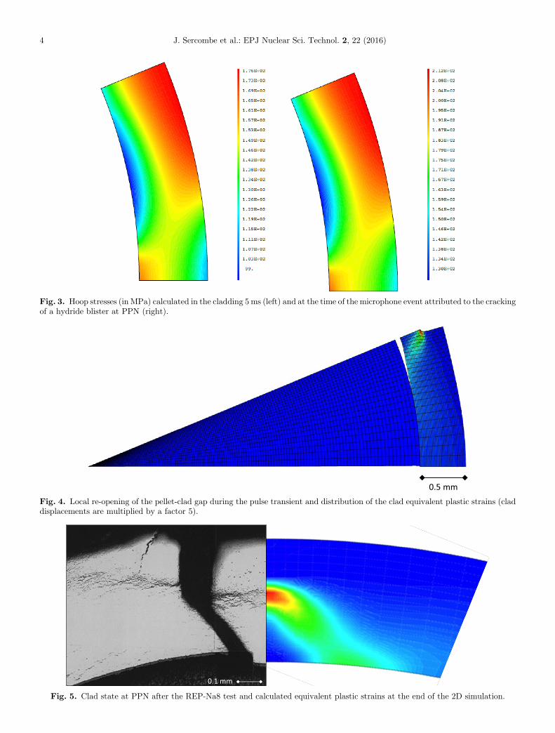
Fig. 3. Hoop stresses (in MPa) calculated in the cladding 5ms (left) and at the time of the microphone event attributed to the crackingof a hydride blister at PPN (right).
0.5 mmFig. 4. Local re-opening of the pellet-clad gap during the pulse transient and distribution of the clad equivalent plastic strains (claddisplacements are multiplied by a factor 5).
0.1 mm
Fig. 5. Clad state at PPN after the REP-Na8 test and calculated equivalent plastic strains at the end of the 2D simulation.
4 J. Sercombe et al.: EPJ Nuclear Sci. Technol. 2, 22 (2016)

J. Sercombe et al.: EPJ Nuclear Sci. Technol. 2, 22 (2016) 5
Figure 4. This bendingmoment leads to the local re-opening(during the pulse) of the pellet-clad gap on a circumferenceof ∼400mm. Thinning of the remaining clad wall is alsoinduced by the blister cracking.
The localization of plastic strains in a band making anangle of ∼45° with the radial direction seems consistent withthe re-opening of the pellet-clad gap. Plastic strains developbetween the blister crack tip and the first location where thepellet is still in contactwith the cladding.The 45° bifurcationobserved after RIA pulse tests is characteristic of a ductilefailure in the plane of the maximum shear stresses. Thequalitative agreement between our simulation and post-testmetallographic observations is illustrated in Figure 5.
Overall, the introduction of a 50% thick hydride blisterin the 2D calculation has some impact on the (average) cladouter diameter variation during the test. The loss ofstiffness induced by the blister cracking leads to an increaseof the (average) clad outer diameter from 0.4% to 0.6%. The
Fig. 6. Equivalent plastic strains calculated at the time of the REP-N(in % of the clad wall thickness).
latter is to be compared with the 0.5% residual strainsestimated post-test from the metallographic radial cut closeto the PPN [3].
5 Impact of hydride blister depth on cladstrains
The 2D simulation of the REP-Na8 test has been used tostudy the impact of the hydride blister depth on the cladstrains. The onset of blister cracking (at the time of themicrophone event) has not been modified since the blister isassumed to behave as the rest of the cladding. Only thenumber of nodes where the boundary conditions arereleased has been changed in the simulations. As illustratedin Figure 6, six configurations with blisters depths equal to25, 50, 60, 70, 80 and 90% of the clad wall thickness, havebeen considered.
a8 fuel rod loss of tightness in function of the hydride blister depth

Average plas�c hoop strain in the 45° shear band
Fig. 7. Location where the average plastic hoop strain in the 45°band is calculated.
6 J. Sercombe et al.: EPJ Nuclear Sci. Technol. 2, 22 (2016)
As can be expected, the increase of the blister depthleads to increasing plastic strains in the 45° band. Tocompare the strain levels in the uncracked clad ligamentsituated beneath the hydride blister, the average plastichoop strain in the 45° band has been used. It was preferredto the maximum plastic strain which obviously dependsgreatly on the mesh refinement and to the average hoopstrain in the cladding which does not account much for thepronounced strain localization at the blister crack tip.
Figure 7 depicts the clad zone where the average plastichoop strain in the 45° band is calculated. In each concentricring of the clad mesh, the maximum plastic hoop strain is
0
0.1
0.2
0.3
0.4
0.5
0.6
0.7
0.8
0.9
1
Aver
age
plas
�c h
oop
stra
in (%
)
Plas�c hoop strain0.5%
Blister cracking
90%
Fig. 8. Calculated evolution of the average plastic hoop strain in thhydride blister depth (in % of the clad thickness).
determined. Since an equidistant mesh is used in the radialdirection, the sum of the maximum plastic hoop strains isthen divided by the number of elements situated beneaththe blister crack tip. The hoop strain was chosen because itcan be compared directly to the local hoop strain measuredfrom wall thinning at the blister crack tip [15]. This is notthe case of the deviatoric plastic strain even if the latter ismore relevant to assess the extension of clad damage inhydrided cladding [16].
The calculated time evolutions of the average plastichoop strain in the 45° shear band are plotted in Figure 8.The times of the microphone events associated to blistercracking and to the rod failure are indicated. If we assumethat the 50% deep hydride blister found at PPN isrepresentative of the initial state of the REP-Na8 cladding,it appears that the allowable maximum plastic strain inthe clad ligament beneath the hydride blister is of the orderof 0.5%.
According to our thermo-mechanical simulation of theREP-Na8 test, failure of the rod is reached at a very lowaverage plastic strain level in the 45° shear band (0.5%).This value can be compared to the 1 to 5% fracture-tip wallthinning estimated by Chung and Kassner from the REP-Na1 post-test metallographies [17] and to a lesser extent tothe 3 to 10% local plastic strains measured by Hermannet al. [15] from burst tests performed at 350 °C on irradiatedZy-4 cladding samples containing large hydride lenses(40–50% of the clad wall thickness). These local strainswere estimated from the local thinning of the clad ligamentssituated beneath the hydride lenses and are therefore closeto our analysis of the calculated plastic strains. The bursttests performed by Hermann et al. [15] were pressure driventests which might not lead to experimental strains directlycomparable to our calculated strains. It may be argued thatthe viscoplastic model of Le Saux et al. [11] does not accountfor the development of cavities and voids in the highly
Time (s) rod failure
80% 70% 60% 50%
25%
e 45° shear band during the REP-Na8 simulation in function of the
0
10
20
30
40
50
60
70
80
90
0 20 40 60 80 100
Enth
alpy
at f
ailu
re a
t PPN
(cal
/g)
Hydride blister depth (in % of the clad thickness)
ALCYONE 2Dsimula�on
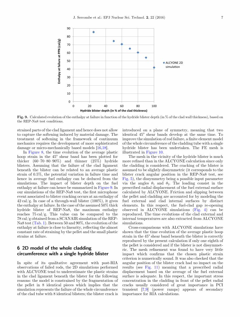
Fig. 9. Calculated evolution of the enthalpy at failure in function of the hydride blister depth (in % of the clad wall thickness), based onthe REP-Na8 test conditions.
J. Sercombe et al.: EPJ Nuclear Sci. Technol. 2, 22 (2016) 7
strained parts of the clad ligament and hence does not allowto capture the softening induced by material damage. Thetreatment of softening in the framework of continuummechanics requires the development of more sophisticateddamage or micro-mechanically based models [16,18].
In Figure 8, the time evolution of the average plastichoop strain in the 45° shear band has been plotted forthicker (60–70–80–90%) and thinner (25%) hydrideblisters. Assuming that the failure of the clad ligamentbeneath the blister can be related to an average plasticstrain of 0.5%, the potential variation in failure time andhence in average fuel enthalpy can be deduced from thesimulations. The impact of blister depth on the fuelenthalpy at failure can hence be summarized in Figure 9. Inour simulations of the REP-Na8 test, the first microphoneevent associated to blister cracking occurs at an enthalpy of42 cal/g. In case of a through-wall blister (100%), it givesthe enthalpy at failure. In the case of the assumed 50% thickhydride blister of REP-Na8, the maximum enthalpyreaches 75 cal/g. This value can be compared to the78 cal/g obtained from a SCANAIR simulation of the REP-Na8 test (Tab. 1). Between 50 and 90%, the evolution of theenthalpy at failure is close to linearity, reflecting the almostconstant rate of straining by the pellet and the small plasticstrains at failure.
6 2D model of the whole claddingcircumference with a single hydride blister
In spite of its qualitative agreement with post-RIAobservations of failed rods, the 2D simulations performedwith ALCYONE tend to underestimate the plastic strainsin the clad ligament beneath the blister for the followingreasons: the model is constrained by the fragmentation ofthe pellet in 8 identical pieces which implies that thesimulation represents the failure of the whole circumferenceof the clad tube with 8 identical blisters; the blister crack is
introduced on a plane of symmetry, meaning that twoidentical 45° shear bands develop at the same time. Toimprove the simulation of rod failure, a finite element modelof the whole circumference of the cladding tube with a singlehydride blister has been undertaken. The FE mesh isillustrated in Figure 10.
The mesh in the vicinity of the hydride blister is muchmore refined than in the ALCYONE calculation since onlythe cladding is considered. The cracking of the blister isassumed to be slightly dissymmetric (it corresponds to theblister crack angular position in the REP-Na8 test, seeFig. 5), the dissymmetry being a possible input parametervia the angles u1 and u2. The loading consist in theprescribed radial displacement of the fuel external surfacecalculated by ALCYONE. Friction and slipping betweenthe pellet and cladding are accounted for by modeling thefuel external and clad internal surfaces by distinctelements. In this respect, the fuel-clad gap re-openingobserved in ALCYONE simulations (Fig. 4) can bereproduced. The time evolutions of the clad external andinternal temperatures are also extracted from ALCYONEsimulations.
Cross-comparisons with ALCYONE simulations haveshown that the time evolution of the average plastic hoopstrain in the 45° shear band beneath the blister is correctlyreproduced by the present calculation if only one eighth ofthe pellet is considered and if the blister is not dissymmet-ric. The mesh refinement was found to have very littleimpact which confirms that the chosen plastic straincriterion is numerically sound. It was also checked that theangular position of the blister crack had no impact on theresults (see Fig. 11) meaning that a prescribed radialdisplacement based on the average of the fuel externalsurface is adequate. In this respect, the important stressconcentration in the cladding in front of the pellet radialcracks usually considered of great importance in PCItransient [7,9] (power ramps) appears of secondaryimportance for RIA calculations.
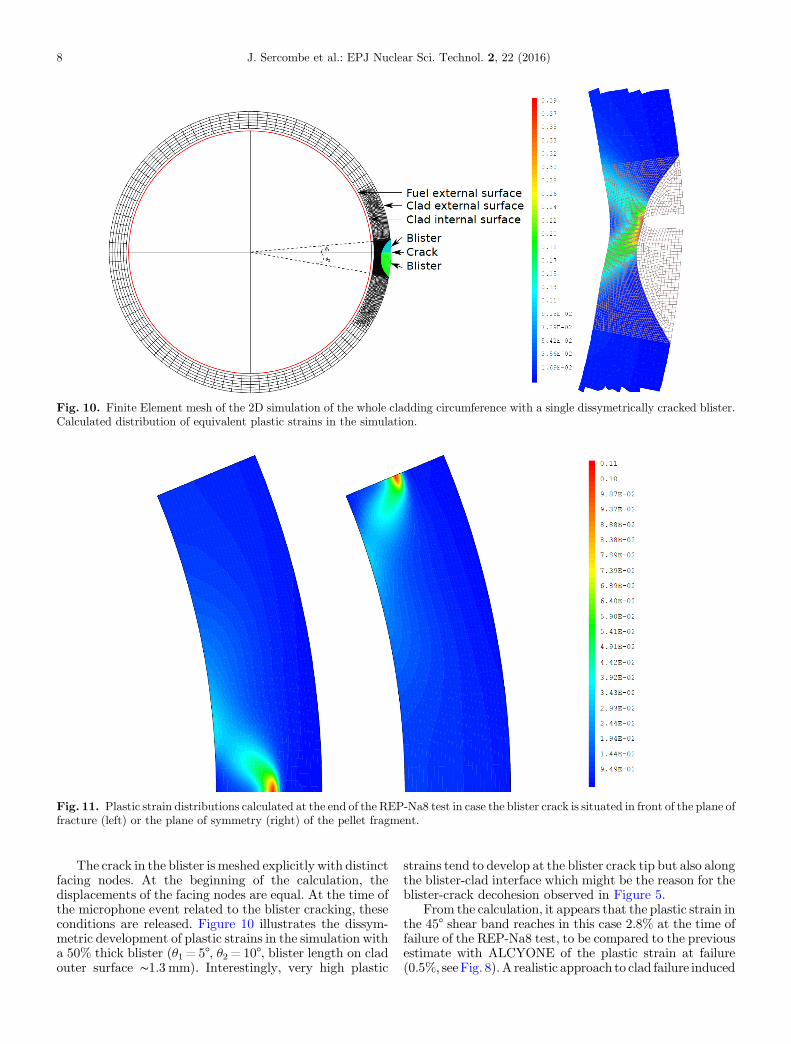
Fig. 10. Finite Element mesh of the 2D simulation of the whole cladding circumference with a single dissymetrically cracked blister.Calculated distribution of equivalent plastic strains in the simulation.
Fig. 11. Plastic strain distributions calculated at the end of the REP-Na8 test in case the blister crack is situated in front of the plane offracture (left) or the plane of symmetry (right) of the pellet fragment.
8 J. Sercombe et al.: EPJ Nuclear Sci. Technol. 2, 22 (2016)
The crack in the blister is meshed explicitly with distinctfacing nodes. At the beginning of the calculation, thedisplacements of the facing nodes are equal. At the time ofthe microphone event related to the blister cracking, theseconditions are released. Figure 10 illustrates the dissym-metric development of plastic strains in the simulation witha 50% thick blister (u1 = 5°, u2 = 10°, blister length on cladouter surface ∼1.3 mm). Interestingly, very high plastic
strains tend to develop at the blister crack tip but also alongthe blister-clad interface which might be the reason for theblister-crack decohesion observed in Figure 5.
From the calculation, it appears that the plastic strain inthe 45° shear band reaches in this case 2.8% at the time offailure of the REP-Na8 test, to be compared to the previousestimate with ALCYONE of the plastic strain at failure(0.5%, seeFig. 8).A realistic approach to clad failure induced

J. Sercombe et al.: EPJ Nuclear Sci. Technol. 2, 22 (2016) 9
by hydride blister cracking during a RIA obviously requiresthe development of a simulation tool able tomodel thewholecircumference of the cladding tube and the evolving PCMI.The impact of blister geometry (length on outer clad surface,dissymmetry of the crack) has not been studied yet in spite ofits potential great importance on plastic strains. Moreover,the limited axial length of the blisters was not considered inthis study since only 2D simulations were performed. Itmight as well contribute to the calculation of greater plasticstrains more consistent with experimental measures.
7 Conclusions
In this paper, the thermo-mechanical response of a fuel rodcontaining a fictitious hydride blister has been studied by2D plane strain simulations of RIA. The blister wasassumed to behave as the rest of the cladding material till aprescribed hoop stress is reached on the outer clad surface.The stress criterion is based on the Finite Element analysisof a PROMETRA laboratory hoop tensile test performedon a highly irradiated sample with a through-wall hydrideblister. The 2D simulations of the REP-Na8 pulse testperformed with ALCYONE led to a qualitatively goodrepresentation of the mixed failure mode encountered inRIA pulse transients on highly corroded fuel rods: thebrittle failure of the pre-pulse 50% thick hydride blister wasfollowed by the development of a diagonally orientedplastic shear band in the remaining clad ligament. Theaverage plastic hoop strain in the shear band at the time offailure of the REP-Na8 test (∼0.5%) was then used toquantify the enthalpy at failure in fuel rods with blister ofincreasing depth (25 to 90% of the clad thickness).
FE simulations of the whole cladding circumference witha single hydride blister were then performed to study theimpact of the blister geometry and of the crack position onthe results. In case of adissymmetric radial crack, highplasticstrains were obtained at the blister crack tip but also alongthe blister-clad interface, which might be the reason for theblister-clad decohesion that can be observed after RIA tests.
The authors would like to thank AREVA and EDF for thefinancial and technical support to this work.
References
1. T. Fuketa, H. Sasajima, Y. Mori, K. Ishijima, Fuel failure andfission gas release in high burnup PWR fuels under RIAconditions, J. Nucl. Mater. 248, 249 (1997)
2. T. Fuketa, T. Sugiyama, Nuclear fuel behavior during RIA, inOCDE/NEA Workshop, Paris, France (2009)
3. J. Papin et al., in Eurosafe Meeting, Paris, France (2003)4. J. Papin, B. Cazalis, J.M. Frizonnet et al., Summary and
interpretation of the CABRI REP-Na program, Nucl.Technol. 157, 230 (2007)
5. V. Georgenthum et al., inWRFPMConference, Seoul, Korea(2008)
6. J. Desquines et al., in Proceedings of the ASTM conferenceon Zirconium in the Nuclear Industry, Stockholm, Sweden(2004)
7. B. Michel, C. Nonon, J. Sercombe, F. Michel, V. Marelle,Simulation of pellet-cladding interaction with the pleiadesfuel performance software environment, Nucl. Technol. 182,124 (2013)
8. CAST3M, http://www-cast3m.cea.fr/9. J. Sercombe, I. Aubrun, C. Nonon, Power ramped cladding
stresses and strains in 3D simulations with burnup-dependentpellet–clad friction, Nucl. Eng. Des. 242, 164 (2012)
10. J. Sercombe et al., in TopFuel Conference, Orlando, Florida,USA (2010)
11. M. Le Saux, J. Besson, S. Carassou, C. Poussard, X. Averty, Amodel to describe the anisotropic viscoplastic mechanicalbehavior of fresh and irradiated Zircaloy-4 fuelcladdings under RIA loading conditions, J. Nucl. Mater.378, 60 (2008)
12. B. Cazalis, J. Desquines, C. Poussard et al., The PROME-TRA program: Fuel cladding mechanical behavior under highstrain rate, Nucl. Technol. 157, 215 (2007)
13. A.H. de Ménibus, Q. Auzoux, O. Dieye et al., Formation andcharacterization of hydride blisters in Zircaloy-4 claddingtubes, J. Nucl. Mater. 449, 132 (2014)
14. V. Macdonald, D. Le Boulch, A.H. de Ménibus, J. Besson, Q.Auzoux, J. Crépin, T. Le Jolu, Fracture of Zircaloy-4 fuelcladding tubes with hydride blisters, Procedia Mater. Sci. 3,233 (2014)
15. A. Hermann et al., in Proceedings of the 15th ASTMconference on Zirconium in the Nuclear Industry, Sunriver,Oregon, USA (2007)
16. M. Le Saux, J. Besson, S. Carassou, A model to describe themechanical behavior and the ductile failure of hydridedZircaloy-4 fuel claddings between 25 °C and 480 °C, J. Nucl.Mater. 466, 43 (2015)
17. H.M. Chung, T.F. Kassner, Cladding metallurgy and fracturebehavior during reactivity-initiated accidents at high burnup,Nucl. Eng. Des. 186, 411 (1998)
18. Y. Udagawa, T. Mihara, T. Sugiyama, M. Suzuki, M. Amaya,Simulation of the fracture behavior of Zircaloy-4 claddingunder reactivity-initiated accident conditions with a damagemechanics model combined with fuel performance codesFEMAXI-7 and RANNS, J. Nucl. Sci. Technol. 51, 208(2014)
Cite this article as: Jérôme Sercombe, Thomas Helfer, Eric Federici, David Leboulch, Thomas Le Jolu, Arthur Hellouin deMénibus, Christian Bernaudat, 2D simulation of hydride blister cracking during a RIA transient with the fuel code ALCYONE, EPJNuclear Sci. Technol. 2, 22 (2016)