29007850R004 NOVA 3G2055 TL2553G v3.0 IM NA UL ULC IC dft...
36
Installation Manual v3.0 Warning: This manual contains information on limitations regarding product use and function and information on the limitations as to liability of the manufacturer. 3G2055 HSPA/3G WIRELESS ALARM COMMUNICATOR SCW 3G Communicator – North America TL2553G ETHERNET/INTERNET AND HSPA/3G DUAL-PATH ALARM COMMUNICATOR SCW 3G / Ethernet Communicator - North America
Transcript of 29007850R004 NOVA 3G2055 TL2553G v3.0 IM NA UL ULC IC dft...
Installation Manualv3.0
Warning: This manual contains information on limitations regarding product use and function and information on the limitationsas to liability of the manufacturer.
3G2055HSPA/3G WIRELESS ALARM COMMUNICATOR
SCW 3G Communicator – North America
TL2553GETHERNET/INTERNET AND HSPA/3G DUAL-PATH ALARM COMMUNICATOR
SCW 3G / Ethernet Communicator - North America

3G Alarm Communicator Installation Manual
2
Warning: Installer Please Read Carefully . . . . . . . . . . . . . . . . . . . . . . . . . . . . . . . . . . . . . . . . . . . . . . . . . . . . . . . . . . . . . . . . 3General Information . . . . . . . . . . . . . . . . . . . . . . . . . . . . . . . . . . . . . . . . . . . . . . . . . . . . . . . . . . . . . . . . . . . . . . . . . . . . . . . 4Communicator Technical Specifications . . . . . . . . . . . . . . . . . . . . . . . . . . . . . . . . . . . . . . . . . . . . . . . . . . . . . . . . . . . . . . . . 5
Features . . . . . . . . . . . . . . . . . . . . . . . . . . . . . . . . . . . . . . . . . . . . . . . . . . . . . . . . . . . . . . . . . . . . . . . . . . . . . . . . . . . . . . . 5UL/ULC Installation Requirements . . . . . . . . . . . . . . . . . . . . . . . . . . . . . . . . . . . . . . . . . . . . . . . . . . . . . . . . . . . . . . . . . . . . 5Communicator Frequency Bands for North America . . . . . . . . . . . . . . . . . . . . . . . . . . . . . . . . . . . . . . . . . . . . . . . . . . . . . . . . 5Ratings . . . . . . . . . . . . . . . . . . . . . . . . . . . . . . . . . . . . . . . . . . . . . . . . . . . . . . . . . . . . . . . . . . . . . . . . . . . . . . . . . . . . . . . . 6Hardware Compatibility . . . . . . . . . . . . . . . . . . . . . . . . . . . . . . . . . . . . . . . . . . . . . . . . . . . . . . . . . . . . . . . . . . . . . . . . . . . . 6Software Compatability . . . . . . . . . . . . . . . . . . . . . . . . . . . . . . . . . . . . . . . . . . . . . . . . . . . . . . . . . . . . . . . . . . . . . . . . . . . . 6
Communicator Pre Installation Configuration. . . . . . . . . . . . . . . . . . . . . . . . . . . . . . . . . . . . . . . . . . . . . . . . . . . . . . . . . . . . 6Connect24™ Account and SIM card Activation . . . . . . . . . . . . . . . . . . . . . . . . . . . . . . . . . . . . . . . . . . . . . . . . . . . . . . . . . . . 6Encryption. . . . . . . . . . . . . . . . . . . . . . . . . . . . . . . . . . . . . . . . . . . . . . . . . . . . . . . . . . . . . . . . . . . . . . . . . . . . . . . . . . . . . . 7
Communicator Configuration with SCW . . . . . . . . . . . . . . . . . . . . . . . . . . . . . . . . . . . . . . . . . . . . . . . . . . . . . . . . . . . . . . . 7Installing CAT 5 Cable (TL2553G only). . . . . . . . . . . . . . . . . . . . . . . . . . . . . . . . . . . . . . . . . . . . . . . . . . . . . . . . . . . . . . . . . 7Inserting/Removing the SIM Card . . . . . . . . . . . . . . . . . . . . . . . . . . . . . . . . . . . . . . . . . . . . . . . . . . . . . . . . . . . . . . . . . . . . . 8Communicator Reset . . . . . . . . . . . . . . . . . . . . . . . . . . . . . . . . . . . . . . . . . . . . . . . . . . . . . . . . . . . . . . . . . . . . . . . . . . . . . . 8Establishing a Communication Channel with the SCW Panel. . . . . . . . . . . . . . . . . . . . . . . . . . . . . . . . . . . . . . . . . . . . . . . . . . 8SMS Command and Control Functions. . . . . . . . . . . . . . . . . . . . . . . . . . . . . . . . . . . . . . . . . . . . . . . . . . . . . . . . . . . . . . . . . . 9Label Programming for SMS Message . . . . . . . . . . . . . . . . . . . . . . . . . . . . . . . . . . . . . . . . . . . . . . . . . . . . . . . . . . . . . . . . . . 9Communicator Placement Test . . . . . . . . . . . . . . . . . . . . . . . . . . . . . . . . . . . . . . . . . . . . . . . . . . . . . . . . . . . . . . . . . . . . . . . 9
Programming Options SectionsETHERNET/Cellular Programming Options . . . . . . . . . . . . . . . . . . . . . . . . . . . . . . . . . . . . . . . . . . . . . . . . . . . . . . . . . . . 10
System Options . . . . . . . . . . . . . . . . . . . . . . . . . . . . . . . . . . . . . . . . . . . . . . . . . . . . . . . . . . . . . . . . . . . . . . . . . . . . . . . . . 10Programming Options. . . . . . . . . . . . . . . . . . . . . . . . . . . . . . . . . . . . . . . . . . . . . . . . . . . . . . . . . . . . . . . . . . . . . . . . . . . . . 12System Test Options [026 - 029] . . . . . . . . . . . . . . . . . . . . . . . . . . . . . . . . . . . . . . . . . . . . . . . . . . . . . . . . . . . . . . . . . . . . . 16Communications Reporting Codes . . . . . . . . . . . . . . . . . . . . . . . . . . . . . . . . . . . . . . . . . . . . . . . . . . . . . . . . . . . . . . . . . . . . 15Ethernet Receiver 1 Options . . . . . . . . . . . . . . . . . . . . . . . . . . . . . . . . . . . . . . . . . . . . . . . . . . . . . . . . . . . . . . . . . . . . . . . . 17Ethernet Receiver 2 Options . . . . . . . . . . . . . . . . . . . . . . . . . . . . . . . . . . . . . . . . . . . . . . . . . . . . . . . . . . . . . . . . . . . . . . . . 17Ethernet Options . . . . . . . . . . . . . . . . . . . . . . . . . . . . . . . . . . . . . . . . . . . . . . . . . . . . . . . . . . . . . . . . . . . . . . . . . . . . . . . . 18Cellular Receiver 1 Options . . . . . . . . . . . . . . . . . . . . . . . . . . . . . . . . . . . . . . . . . . . . . . . . . . . . . . . . . . . . . . . . . . . . . . . . 18Cellular Receiver 2 Options . . . . . . . . . . . . . . . . . . . . . . . . . . . . . . . . . . . . . . . . . . . . . . . . . . . . . . . . . . . . . . . . . . . . . . . . 19Cellular Options . . . . . . . . . . . . . . . . . . . . . . . . . . . . . . . . . . . . . . . . . . . . . . . . . . . . . . . . . . . . . . . . . . . . . . . . . . . . . . . . . 19Command and Control Options . . . . . . . . . . . . . . . . . . . . . . . . . . . . . . . . . . . . . . . . . . . . . . . . . . . . . . . . . . . . . . . . . . . . . . 20SMS Command and Control Functions. . . . . . . . . . . . . . . . . . . . . . . . . . . . . . . . . . . . . . . . . . . . . . . . . . . . . . . . . . . . . . . . . 21SMS Command and Control Response . . . . . . . . . . . . . . . . . . . . . . . . . . . . . . . . . . . . . . . . . . . . . . . . . . . . . . . . . . . . . . . . . 22Receiver Diagnostic Testing . . . . . . . . . . . . . . . . . . . . . . . . . . . . . . . . . . . . . . . . . . . . . . . . . . . . . . . . . . . . . . . . . . . . . . . . 24System Information (Read Only) . . . . . . . . . . . . . . . . . . . . . . . . . . . . . . . . . . . . . . . . . . . . . . . . . . . . . . . . . . . . . . . . . . . . . 24System Reset Defaults . . . . . . . . . . . . . . . . . . . . . . . . . . . . . . . . . . . . . . . . . . . . . . . . . . . . . . . . . . . . . . . . . . . . . . . . . . . . 24Communicator Troubleshooting. . . . . . . . . . . . . . . . . . . . . . . . . . . . . . . . . . . . . . . . . . . . . . . . . . . . . . . . . . . . . . . . . . . . . . 25
Programming Worksheets SectionsEthernet/Cellular Programming Worksheets . . . . . . . . . . . . . . . . . . . . . . . . . . . . . . . . . . . . . . . . . . . . . . . . . . . . . . . . . . . . 29
System Options . . . . . . . . . . . . . . . . . . . . . . . . . . . . . . . . . . . . . . . . . . . . . . . . . . . . . . . . . . . . . . . . . . . . . . . . . . . . . . . . . 29Programming Options. . . . . . . . . . . . . . . . . . . . . . . . . . . . . . . . . . . . . . . . . . . . . . . . . . . . . . . . . . . . . . . . . . . . . . . . . . . . . 29System Test Options [026 - 029] . . . . . . . . . . . . . . . . . . . . . . . . . . . . . . . . . . . . . . . . . . . . . . . . . . . . . . . . . . . . . . . . . . . . . 29System Test Options [026 - 029] . . . . . . . . . . . . . . . . . . . . . . . . . . . . . . . . . . . . . . . . . . . . . . . . . . . . . . . . . . . . . . . . . . . . . 29Ethernet Receiver 1 Options . . . . . . . . . . . . . . . . . . . . . . . . . . . . . . . . . . . . . . . . . . . . . . . . . . . . . . . . . . . . . . . . . . . . . . . . 30Ethernet Receiver 2 Options . . . . . . . . . . . . . . . . . . . . . . . . . . . . . . . . . . . . . . . . . . . . . . . . . . . . . . . . . . . . . . . . . . . . . . . . 30Ethernet Options . . . . . . . . . . . . . . . . . . . . . . . . . . . . . . . . . . . . . . . . . . . . . . . . . . . . . . . . . . . . . . . . . . . . . . . . . . . . . . . . 30Cellular Receiver 1 Options . . . . . . . . . . . . . . . . . . . . . . . . . . . . . . . . . . . . . . . . . . . . . . . . . . . . . . . . . . . . . . . . . . . . . . . . 30Cellular Receiver 2 Options . . . . . . . . . . . . . . . . . . . . . . . . . . . . . . . . . . . . . . . . . . . . . . . . . . . . . . . . . . . . . . . . . . . . . . . . 31Cellular Options . . . . . . . . . . . . . . . . . . . . . . . . . . . . . . . . . . . . . . . . . . . . . . . . . . . . . . . . . . . . . . . . . . . . . . . . . . . . . . . . . 31System Information (Read Only) . . . . . . . . . . . . . . . . . . . . . . . . . . . . . . . . . . . . . . . . . . . . . . . . . . . . . . . . . . . . . . . . . . . . . 33System Reset Defaults . . . . . . . . . . . . . . . . . . . . . . . . . . . . . . . . . . . . . . . . . . . . . . . . . . . . . . . . . . . . . . . . . . . . . . . . . . . . 33
End User Licence Agreement . . . . . . . . . . . . . . . . . . . . . . . . . . . . . . . . . . . . . . . . . . . . . . . . . . . . . . . . . . . . . . . . . . . . . . . 34
Limited Warranty . . . . . . . . . . . . . . . . . . . . . . . . . . . . . . . . . . . . . . . . . . . . . . . . . . . . . . . . . . . . . . . . . . . . . . . . . . . . . . . . 35
TABLE OF CONTENTS

3G Alarm Communicator Installation Manual Warning: Installer Please Read Carefully
3
WARNING: INSTALLER PLEASE READ CAREFULLY
Note to InstallersThe Warnings on this page contain vital information. As the only individual incontact with system users, it is the installer’s responsibility to bring each item inthis Warning to the attention of all users of this system.
System FailuresThis system has been carefully designed to be as effective as possible. There arecircumstances, however, involving fire, burglary, or other types of emergencieswhere it may not provide protection. Any alarm system of any type may be com-promised deliberately or may fail to operate as expected for a variety of reasons.Some, but not all, of the reasons may be:
Access by IntrudersIntruders may enter through an unprotected access point, circumvent a sensingdevice, evade detection by moving through an area of insufficient coverage, dis-connect a warning device, or interfere with or prevent the proper operation of thesystem.
Component FailureAlthough every effort has been made to make this system as reliable as possible,the system may fail to function as intended due to the failure of a component.Compromise of Radio Frequency (Wireless) DevicesSignals may not reach the receiver under all circumstances which could includemetal objects placed on or near the radio path or deliberate jamming or otherinadvertent radio signal interference.
Criminal KnowledgeThis system contains security features which were known to be effective at thetime of manufacture. It is possible for persons with criminal intent to developtechniques which reduce the effectiveness of these features. It is important thatyour security system be reviewed periodically to ensure that its features remaineffective and that it is updated or replaced if it is found that it does not provide theprotection expected.
Failure of Replaceable BatteriesThis system’s wireless transmitters have been designed to provide several yearsof battery life under normal conditions. The expected battery life is a function ofthe device environment, usage, and type. Ambient conditions such as highhumidity, high or low temperatures, or large temperature fluctuations may reducethe expected battery life. While each transmitting device has a low battery moni-tor which identifies when the batteries need to be replaced, this monitor may failto operate as expected. Regular testing and maintenance will keep the system ingood operating condition.
Inadequate InstallationA security system must be installed properly in order to provide adequate protec-tion. Every installation should be evaluated by a security professional to ensurethat all access points and areas are covered. Locks and latches on windows anddoors must be secure and operate as intended. Windows, doors, walls, ceilingsand other building materials must be of sufficient strength and construction toprovide the level of protection expected. A reevaluation must be done during andafter any construction activity. An evaluation by the fire and/or police departmentis highly recommended if this service is available.
Inadequate TestingMost problems that would prevent an alarm system from operating as intendedcan be found by regular testing and maintenance. The complete system should betested weekly and immediately after a break-in, an attempted break-in, a fire, astorm, an earthquake, an accident, or any kind of construction activity inside oroutside the premises. The testing should include all sensing devices, keypads,consoles, alarm indicating devices, and any other operational devices that are partof the system.
Insufficient TimeThere may be circumstances when the system will operate as intended, yet theoccupants will not be protected from an emergency due to their inability torespond to the warnings in a timely manner. If the system is remotely monitored,the response may not occur in time to protect the occupants or their belongings.
Motion DetectorsMotion detectors can only detect motion within the designated areas as shown intheir respective installation instructions. They cannot discriminate betweenintruders and intended occupants. Motion detectors do not provide volumetricarea protection. They have multiple beams of detection and motion can only bedetected in unobstructed areas covered by these beams. They cannot detectmotion which occurs behind walls, ceilings, floor, closed doors, glass partitions,glass doors or windows. Any type of tampering whether intentional or uninten-tional such as masking, painting, or spraying of any material on the lenses, mir-rors, windows or any other part of the detection system will impair its properoperation.Passive infrared motion detectors operate by sensing changes in temperature.However their effectiveness can be reduced when the ambient temperature risesnear or above body temperature or if there are intentional or unintentional sourcesof heat in or near the detection area. Some of these heat sources could be heaters,radiators, stoves, barbeques, fireplaces, sunlight, steam vents, lighting and so on.
Power FailureControl units, intrusion detectors, smoke detectors and many other securitydevices require an adequate power supply for proper operation. If a device oper-ates from batteries, it is possible for the batteries to fail. Even if the batteries havenot failed, they must be charged, in good condition and installed correctly. If adevice operates only by AC power, any interruption, however brief, will renderthat device inoperative while it does not have power. Power interruptions of anylength are often accompanied by voltage fluctuations which may damage elec-tronic equipment such as a security system. After a power interruption hasoccurred, immediately conduct a complete system test to ensure that the systemoperates as intended.
Security and InsuranceRegardless of its capabilities, an alarm system is not a substitute for property orlife insurance. An alarm system also is not a substitute for property owners, rent-ers, or other occupants to act prudently to prevent or minimize the harmful effectsof an emergency situation.
Smoke DetectorsSmoke detectors that are a part of this system may not properly alert occupants ofa fire for a number of reasons, some of which follow. The smoke detectors mayhave been improperly installed or positioned. Smoke may not be able to reach thesmoke detectors, such as when the fire is in a chimney, walls or roofs, or on theother side of closed doors. Smoke detectors may not detect smoke from fires onanother level of the residence or building.Every fire is different in the amount of smoke produced and the rate of burning.Smoke detectors cannot sense all types of fires equally well. Smoke detectorsmay not provide timely warning of fires caused by carelessness or safety hazardssuch as smoking in bed, violent explosions, escaping gas, improper storage offlammable materials, overloaded electrical circuits, children playing withmatches, or arson.Even if the smoke detector operates as intended, there may be circumstanceswhen there is insufficient warning to allow all occupants to escape in time toavoid injury or death.
Telephone LinesIf telephone lines are used to transmit alarms, they may be out of service or busyfor certain periods of time. Also an intruder may cut the telephone line or defeatits operation by more sophisticated means which may be difficult to detect.
Warning Devices Warning devices such as sirens, bells, horns, or strobes may not warn people orwaken someone sleeping if there is an intervening wall or door. If warningdevices are located on a different level of the residence or premise, then it is lesslikely that the occupants will be alerted or awakened. Audible warning devicesmay be interfered with by other noise sources such as stereos, radios, televisions,air conditioners, other appliances, or passing traffic. Audible warning devices,however loud, may not be heard by a hearing-impaired person.

Keypad Data Display 3G Alarm Communicator Installation Manual
4
Domain Name Service (DNS) programming is not permitted in UL/ULC listed systems.
KEYPAD DATA DISPLAY
• Section-Toggle Options: The number is displayed when Toggle is ON. The number is not displayed when Toggle is OFF. (e.g.,Toggle Options displays: “[--3--6--]”. Options 3 and 6 are ON, all others are OFF). Pressing keys 1 through 8 will alternately turnthe Toggle ON and OFF.
• HEX/Decimal Data: Values that are provided with two defaults, separated by a / character, use the format: hexadecimal followed bydecimal equivalent (e.g., Default [0BF5/3061]). Hexadecimal numbers are shown, with all leading zeroes, to the full field lengthdefined for the number.
ENTERING DATA FROM KEYPAD
To enter data at the keypad, press the number key, from the table below, to select the character that you want. Pressing the number keyrepeatedly will scroll through the characters available for that key. Press the [*] key and use [<] [>] keys to scroll to one of the followingselections: (Press [*] to select the Option.)
• ASCII Entry. Use this mode to enter ASCII characters from the keypad.• Clear to End. This selection will clear the remainder of the display.• Clear Display.This selection will completely erase all entries on the display.• Change Case. Toggles between upper/lower case depending on current selection.NOTE: The “0” on the keypad is used to delete characters.
ENTERING ASCII CHARACTERS
To enter American Standard Code for Information Interchange (ASCII) characters at the keypad, perform the following:
1. Press [*] and use [<] [>] keys to scroll to “ASCII Entry”.
2. Press [*] to select ASCII entry mode.
3. Use the [<] [>] keys to scroll to display the ASCII character you want to use and press [*] to accept.
4. Press [*] to exit ASCII character entry mode and return to normal entry.
NOTE: Authorized access to Connect24 (3G2055/TL2553G) is required to modify any Ethernet/Cellular Programming Section. Spe-cific panel sections must be configured for proper operation of the Communicator with the panel.
MOUNTING CONSIDERATIONS
The Cellular/Ethernet Communicator is a fixed, wall-mounted unit and shall be installed in the location specified in these instructions.The equipment enclosure must be fully assembled and closed, with all the necessary screws/tabs and it must be secured to a wall beforeoperation. Internal wiring must be routed in a manner that prevents:• Excessive strain on wire and on terminal connections,• Interference between power limited and non power limited wiring,• Loosening of terminal connections, or• Damage of conductor insulation.
WARNING: NEVER INSTALL THIS EQUIPMENT DURING A LIGHTNING STORM!
The Installer must instruct the System user on each of the following items:• This manual shall be used in conjunction with the Alarm controller manual; All the safety instructions specified within that manual
shall be observed.• Do not attempt to service this product. Opening or removing covers may expose the user to dangerous
voltages or other risks.• Any servicing shall be referred to trained service person only.• Use authorized accessories only with this equipment.Cellular Coverage for Alarm Communicator OperationThe HSPA/3G performance of the 3G2055 and TL2553G Alarm Communicators depends greatly on Cellular network coverage. TheSCW (with internal Alarm Communicator) should not be mounted in the final location without first ensuring that Cellular radio recep-tion is adequate for communication using the HSPA/3G paths. Perform the “Communicator Placement Test” on page 9.
GENERAL INFORMATION
Table 1: Data Entry at Keypad
Key Value Key Value Key Value1 1-A-B-C 4 4-J-K-L 7 7-S-T-U
2 2-D-E-F 5 5-M-N-O 8 8-V-W-X
3 3-G-H-I 6 6-P-Q-R 9 9-Y-Z-0

3G Alarm Communicator Installation Manual General Information
5
GENERAL INFORMATION
All versions of the HSPA/3G and Ethernet Alarm Communicator, operate on a HSPA/3G network and are housed inside the Self Con-tained Wireless (SCW) 9055/9057. The Communicators use an Internal Antenna only.Each version of Alarm Communicators covered by this Installation Manual are described below:3G2055: A High Speed Packet Access/Global System for Mobile (HSPA/3G) wireless Alarm Communicator that sends alarm communica-tion to Sur-Gard System I, II, III (SG-DRL3IP), and IV (SG-DRL4IP) central station receivers via a HSPA/3G digital cellular network.TL2553G: Is a dual-path Cellular/Ethernet Alarm Communicator that sends alarm communication to Sur-Gard System I, II, III, and IVcentral station receivers through Ethernet/Internet or a HSPA/3G digital cellular network.The dual path Communicator can be used as either a backup or primary Communicator. The Communicator supports Internet Protocol(IP) transmission of panel and internal events over Ethernet/Internet and/or HSPA/3G.
NOTE: For North America the following model names are available: 3G2055-NA and TL2553G-NA.
CAUTION:
• Do not stay close to the equipment during device operation and to do not touch any exposed wires and other conductive surfaces,• Recycle the battery according to the local rules and regulations.NOTE: Prior to installation of the 3G2055 or TL2553G Communicator, confirm with your local carrier that the HSPA/3G network is
available and active in the area where the Communicator will be installed, and that the location provides a radio signal strength that is adequate for uninterrupted service.
FEATURES
UL/ULC INSTALLATION REQUIREMENTS
• For ULC Residential fire and burglary applications the 3G2055/TL2553G can be used as primary communication channel via eitherCellular or Ethernet (as applicable) or as a back-up in conjunction with the Digital Alarm Communicator Transmitter (DACT). Testtransmission every 24hours shall be enabled on each channel.
• For UL Residential fire and burglary applications the 3G2055/TL2553G can be used as primary communication channel via eitherCellular or Ethernet, or as a back-up in conjunction with the DACT. (30 day test transmission is required on each channel).
COMMUNICATOR FREQUENCY BANDS FOR NORTH AMERICA
COMMUNICATOR TECHNICAL SPECIFICATIONS
• 128-bit Advanced Encryption Standard (AES) encryption via HSPA/3G and Ethernet/Internet.• Activating, initializing and remote programming through Connect 24.• Back up or primary HSPA/3G/2G alarm communication. • Does not require an external HSPA/3G/2G antenna.• Ethernet LAN/WAN 10/100 BaseT (TL2553G only).• Full event reporting to central station.• Fully redundant Ethernet/Internet and HSPA/3G/2G Dual-path Alarm Communication (TL2553G only).• Individual Ethernet and/or HSPA/3G periodic test transmission.• 2-way audio (listen-in feature) provided over Cellular.• Integrated call routing.• Remote Firmware upgrade capability of the Communicator and Panel Firmware via Ethernet and/or HSPA/3G radio.• Dual-Band Operation: 850 MHz, and 1900 MHz. (North America only)• CID and SIA format reporting.• Subscriber Identity Module (SIM) card included with Communicator. (North America only)• Supervision heartbeats via HSPA/3G/2G and/or Ethernet/Internet.
Table 2: 2G Frequency Bands
Transmit Direction Cellular 850 North America PCS 1900 North America
Transmit Frequency 824 MHz to 849 MHz 1850 MHz to 1910 MHz
Receive Frequency 869 MHz to 894 MHz 1930 MHz to 1990 MHz
Table 3: 3G Frequency Bands
Transmit Direction UMTS 850 North America, International UMTS 1900 North America
Transmit Frequency 824 MHz to 849 MHz 1850 MHz to 1910 MHz
Receive Frequency 869 MHz to 894 MHz 1930 MHz to 1990 MHz

Ratings 3G Alarm Communicator Installation Manual
6
RATINGS
HARDWARE COMPATIBILITY
Products or components of products, which perform communications functions only shall comply with the requirements applicable tocommunications equipment as specified in UL60950 or CAN/CSA-C22.2 No. 60950-1, Information Technology Equipment - Safety -Part 1: General Requirements. Where network interfaces are internal to the control unit or receiver, compliance to CAN/CSA-C22.2No. 60950-1 is adequate. Such components include, but are not limited to: hubs; routers; NIDs; Third party communications serviceproviders; DSL modems; and Cable modems.
SOFTWARE COMPATABILITY
The Communicator is compatible with the following software:• Connect24 Using: Simple Messaging System (SMS) Protocol.• Connect24 Remote Flash. Using: Internet Protocol (IP) using Trivial File Transfer Protocol (TFTP).
CONNECT24™1 ACCOUNT AND SIM CARD ACTIVATION
(Before Installation)
Installation of the Communicator requires activation with Connect24 before operation. Dealer application forms and additional infor-mation on the Connect24 Voice Response Unit (VRU) and graphical user interface (GUI) can be found at http://www.Connect24.comor by telephone at: USA 1-888-251-7458 or CANADA 1-888-955-5583.IMPORTANT: Prior to installing a 3G2055 or TL2553G Communicator, contact your monitoring station to determine if it is a masterre-seller or visit http://www.Connect24.com to become an authorized dealer. In either instance, you will require a Profile Number,Installer ID Number, and an Installer Password. Perform the following pre installation:1. Retrieve the installer account and password from the master reseller, or from Connect24 directly.
2. Connect your browser to the Connect 24 website at: http://www.Connect24.com or call VRU number.
3. Log in to the Connect24 website using your installer account and password.
4. Perform the following steps in a Connect24 session to activate the SIM card and initialize programming:a. Navigate to the Initialize an account section.b. Select Profile (This information will be provided by the master reseller or by Connect24).c. Select Product Module.d. Enter the SIM card number.e. Click Next then enter in all relevant information as required.f. Confirm all information is entered correctly before submitting.
5. Repeat Step 4 to program another SIM card (i.e. another Subscriber), or log out from Connect24.
Table 4: Communictor Electrical Ratings
Model 3G2055Cellular Only
TL2553GEthernet and Cellular
Power Supply Ratings
Input Voltage 3.5 / 3.9 / 4.2 VDC (min / NOM / MAX) from the SCW panel
Current Consumption 75 mA 100 mA
Standby Current (@ 3.7V) 75 mA 100 mA
Alarm (Transmitting) Current) 400 mA @ 3.7V during transmission
Antenna Specifications
Dual band Antenna See Table 2 and Table 3
Environmental Specifications
Operating Temperature 0°C - 49°C (32°F- 120°F)Humidity 5% ~ 85% relative humidity, non-condensing
Mechanical Specifications
Board Dimensions (mm) 109 x 110
Weight (grams) 60 65
Table 5: Compatibility
Communicator Receiver/ControlPanel Description
3G2055
TL2553G
Receiver
SG System I, v1.14+SG System II, v2.11+SG-DRL3-IP, v2.3+SG-DRL4-IP, v1.2+
Control Panel SCW9055/SCW9057 V1.00
COMMUNICATOR PRE INSTALLATION CONFIGURATION
1. Connect24, DSC, and DLS IV are Registered Trademarks of Tyco International Ltd. and its respective Companies. All Rights Reserved.

3G Alarm Communicator Installation Manual Encryption
7
6. When you are at the physical installation site, the Communicator will automatically connect and download its programming fromConnect24 once the unit is initialized.
NOTE: Following initial installation, you can log in to the Connect24 website at any time to re-configure the Communicator remotely, using the account created for this installation. For more information, refer to the Connect24 website.
Before leaving the installation site, the Communicator TL2553G shall be connected via an APPROVED (acceptable to the local authorities) Network Interface Device (NID) (e.g., for UL Installations, U60950 listed NID). All wiring shall be performed according to the local electrical codes.
ENCRYPTION
The Communicator uses 128 Bit AES Encryption. Encryption can only be enabled from the monitoring station receiver. Each receivercan independently have encryption enabled or disabled. When encryption is enabled, the central station will configure the device toencrypt communications the next time the Communicator module performs a communication to that receiver. NOTE: Packets will start being encrypted only after the next event is sent to that receiver, or if the unit is restarted.
NOTE: The Alarm Communicator is installed in the SCW prior to shipment by Digital Secu-rity Controls (DSC). The Factory Installation includes insertion of the SIM card. The SCW should not be mounted in its final location without performing a Communicator Test to ensure adequate HSPA/3G coverage for the 3G2055 and TL2553G Alarm Communicators
INSTALLATION LOCATION
The Communicator shall be installed in anindoor location only.This HSPA/3G/Ethernet Communicator shallbe installed by Service Persons only. (ServicePerson is defined as a person having appropri-ate technical training and experience necessaryto be aware of hazards to which that personmay be exposed in performing a task and ofmeasures to minimize the risks to that personor other persons). The Communicator shall beinstalled and used within an environment thatprovides the pollution degree max 2, over volt-
ages category II, in non-hazardous, indoor locations only. This manual shall be used with the Installation Manual of the alarm controlpanel which is connected to the HSPA/3G/Ethernet Communicator. All instructions specified within the control panel manual must beobserved.All the local rules imposed by local electrical codes shall be observed and respected during installation.
INSTALLING CAT 5 CABLE (TL2553G ONLY)A Category 5 (CAT 5) ethernet cable must be run from a source with Ethernet/Internetconnectivity to the Communicator module, inside the Self Contained Wireless ControlPanel cabinet. The Communicator end of the cable must have an RJ-45 plug, which con-nects to the Communicator’s RJ-45 jack. All requirements for installation of CAT5 eth-ernet cable must be observed for correct operation of the Communicator, including, butnot limited to, the following:• Do NOT strip off cable sheathing more than required for proper termination.• Do NOT kink/knot cable.• Do NOT crush cable with cable ties. • Do NOT untwist CAT5 pairs more than 1.2cm (½”).• Do NOT splice cable.• Do NOT bend cable at right angles or make any other sharp bends.
NOTE: CAT5 specification requires that any cable bend must have a minimum 5 cm (2 in.) bend radius. Maximum length of CAT 5 cable is 100m (328 ft.).
NOTE: The Ethernet cable shall not be visible when the installation is complete unless the install is a surface mount installation.
COMMUNICATOR CONFIGURATION WITH SCW
Figure 1: Communication Board Connection Points
Mounting Hole
Mounting Hole
SIM Card Holder
RJ-45 Connector(TL2553G only)
RJ-45 ConnectorDG
0009
635
Figure 2: RJ-45 Pinout

Inserting/Removing the SIM Card 3G Alarm Communicator Installation Manual
8
INSERTING/REMOVING THE SIM CARD
1. Remove the front cover of the SCW Control Panel to access SIM card holder.
2. Remove power from the SCW and disconnect the backup batteryconnections.
3. On the SIM card holder push gently to slide the cover towardsOPEN as indicated by the arrow on SIM holder. This will unlatchthe SIM card holder on the side furthest from edge of the Communi-cator. See Figure 1.
4. Lift up the SIM card holder from the side that is not hinged.
NOTE: The SIM card can be damaged by bending or scratching contacts. Use caution when handling the SIM card.
5. Insert or remove the SIM card, noting the orientation of the notches on the SIM card and the SIM card holder.
6. When inserting a SIM card, insert the card in the proper orientation and gently push the SIM card holder down and slide the holderas indicated by the arrow on SIM holder, to LOCK.
7. Apply AC power to panel, and replace the panel cover.
NOTE: If two way audio is enabled you will NOT be able to swap the SIM card with another card.
COMMUNICATOR RESETThe Communicator can be reset by cycling the power on the SCW.
ESTABLISHING A COMMUNICATION CHANNEL WITH THE SCW PANEL.The Communicator interfaces to the SCW through a keyed 16 pin Ribbon cable. See Table 6 . The key prevents incorrect connection ofthe ribbon cable connector to the SCW and Communicator. The pinout for the Ribbon cable is provided in the Table below:
Establishing a communication channel between the Communicator and the SCW is critical to ensuring the desired operation of the twounits. The following steps must be completed during the on-site installation. Program the following to ensure that the Communicatorand the panel will work together as intended.Initial Programming of Communicator and SCW1. Enter [*][8][Installer Code] [Section Number] for panel programming. Record any values that are modified from their default, in the
appropriate Programming Worksheets.
NOTE: When programming Toggle Options, the toggle is ON when the number is displayed and OFF when the number is not dis played. (e.g., [1 - - - 5 - - - ], Toggle Options 1 and 5 are ON, all others are OFF).
2. Panel Section [167] Cellular/Ethernet Interface Communications ‘Wait for ACK’: Default value is: 060 seconds.
3. When the communicator is installed with the SCW panel, 4 telephone numbers are available to backup one another. You can set upthese 4 telephone numbers to perform in one of two ways: Backup dialling or Alternate dialling.a. Backup dialling: each of the 4 telephone numbers will make 5 dialling attempts in turn, before an FTC trouble is displayed on the
keypad.b. Alternate dialling: each telephone number makes 1 dialling attempt before moving on to the next number, cycling through each
of the 4 numbers for a total of 5 times each. If all 4 numbers fail the 5 attempts, an FTC trouble is displayed on the keypad.4. Panel Sections [301], [302], [303], and [305] can be configured as Primary communication paths.
a. Panel Sections [302], [303], and [305] may also be configured for backup or redundant communications by using Panel Section(s)[383] or [351] - [376]. Refer to the SCW panel Installation Manual for more information.
b. If a valid telephone number is programmed, communications will use Public Switched Telephone Network (PSTN). Entering a 4digit hexadecimal value for a telephone number will change the call routing to the Communicator, as determined by the numberprogrammed:DCAAF: Internal (All Receivers). Signals will be routed depending on Section [851] [006] programming.DCBBF: Ethernet Receiver 1 (Primary). (Not available for 3G2055).DCCCF: Ethernet Receiver 2 (Backup). (Not available for 3G2055).DCDDF: Cellular Receiver 1 (Primary).DCEEF: Cellular Receiver 2 (Backup).
NOTE: Add a single ‘F’ as a suffix to the 4 digit hex number to populate the unused remainder of the 32 character field.
5. Panel Section [350]: If any of the phone numbers have been programmed as DCAA, DCBB, DCCC, DCDD, or DCEE, panel Sec-tion [350] must be set to [04] if SIA format or [03] if Contact ID (CID) format is used by control panel.
Table 6: Communicator Ribbon cable to SCW
Pin # Signal Pin # Signal
1 PC-Link TX 2 PC-Link RX
3 GND 4 Vref
5 Vref 6 GND
7 AUD-OUT_N 8 AUD-OUT_P
9 AUD-IN_P 10 AUD-IN_N
11 GND 12 SI
13 GND 14 SO
15 GND 16 Wall Tamper
SIM Card PinoutsDG0009396
Figure 3: SIM Card Pinouts

3G Alarm Communicator Installation Manual SMS Command and Control Functions
9
6. Panel Section [382]: Toggle Option [5], ‘GS/IP Module Enabled’, must be set to ON.
7. Panel Section [401]: Toggle Option [1] must be set to ON in order to perform panel DLS session through Cellular or Ethernet datachannel.
8. Panel section [310], account code, auto syncs with the communicator account code in section [021]. The panel account code([*][8][installer code] [310]), will overwrite the communicator account code section ([*][8][installer code] [850] [021]) if pro-grammed differently.
NOTE: Keep a record of the SIM card telephone number, it is required by users for SMS Command and Control functions. (The num-ber can be recorded in the Programming Worksheets Section of this document, under Option [996]). Due to the nature of the SIM card activation process with Cellular network carriers, it can take up to 24 hours for SIM card activation to be complete.
SMS COMMAND AND CONTROL FUNCTIONSSMS Command and Control is available on SCW9055/57 panels. Users can send SMS text messages from their mobile phone to theGSM phone number assigned to their system. Commands are only accepted from telephone numbers that have been programmed inSections [311]-[318]. The system will reject messages sent from telephone numbers that are not on the programmed list.When the received SMS text matches a valid Section message, the function is performed on the control panel. Text messages are notcase sensitive and extra spaces are ignored. A User Access Code may be required for some SMS messages.The SMS Message format is in 3 parts: Command, Partition Label (or only the partition number), and Access Code.If an Access Code is included in the message, it is sent to the control panel for validation, along with the requested function.If the panel is configured to require an Access Code and the code is not sent (or invalid) the panel will fail the function (unsuccessful).If the panel fails the function, an SMS response message is sent to the user. The SMS response will echo the command sensat, followedby the label “unsuccessful”. (e.g., “night arm partition 2 1234 unsuccessful”).The partition label or partition number may be excluded from the SMS request in a single partition system (e.g., disarm 9123).
NOTE: The GSM phone number can be viewed in Section [851] [996], and/or [851] [229] or by entering *6, then scrolling down to “SMS Programming” and scrolling down to “Cellular phone No”.
LABEL PROGRAMMING for SMS MESSAGEProgrammable Labels can not be modified in Connect24, use DLS IV for label programming only, if labels need to be modified. Beforeinitiating remote programming, record your network’s Public IP Address and port for incoming DLS IV connections.
1. Run the DLS IV software on your computer. DLS IV will connect to the unit, using the Public IP address, and make an Ethernet con-nection. If the Ethernet connection fails, DLS IV will report an error and prompt you to connect using Cellular.
NOTE: If required, download the DLS IV software from DSC: http://www.dsc.com/index.php?n=library#self. If you select Cellular connection, DLS will request Connect24 to send an outgoing SMS message to the unit.
2. Connect24 will confirm that the account has DLS service and will provide the Public IP address and port number of the DLS serverin an SMS message.
3. SMS message will establish a connection to your computer’s DLS IV software (to change programming labels only).
4. Create an account for the panel/Communicator, select the Communicator type (e.g., SMS - TL2553G) and enter all relevant infor-mation in SMS section.
NOTE: The Cellular telephone number will also be required by the user, to send SMS Command and Control messages to their system.
5. Program the account information, then click Global Download and choose SMS as the Connection Type. Click OK.
6. The download path configured in Programming Section [005] Toggle Option[4] determines the Cellular or Ethernet path to be used.
COMMUNICATOR PLACEMENT TEST
(3G2055/TL2553G only)1. Using the keypad enter the installer mode: [*][8] [installer code] [850].
2. View and record the number of bars showing on the SCW LCD.
3. Compare with the number of bars indicated in the “CSQ Levels” column shown in Table 7 .
4. If 3 or more bars are shown, the location is GOOD and no further action is required.
5. If the location is BAD, move the SCW to various suitable locations until 3 or more bars are obtained.
NOTE: The communicator is capable of indicating signal strength even without an active SIM, but signal indication may take up to 1-
2 minutes.1
Table 7: Communicator CSQ Levels
Signal Strength CSQ Level Signal Level dBm Installer Action
No Signal 0 -108.8 Check if Cellular coverage is active in your area.
1 Bar 1 to 4 -108d to -103Location is BAD. Not suitable for Cellular operation.
2 Bars 5 to 6 -102 to -99
3 Bars 7 to 10 -98d to -91
Location is GOOD.4 Bars 11 to 13 -90 to -85
5 Bars 14 and higher -84 and higher

System Options 3G Alarm Communicator Installation Manual
10
The Programming Sections described in this document can be viewed at the SCW LCD. To start programming enter: [*][8][installercode] [851][# # # ], Where # # # is the 3 digit Section number referenced in this section. The Programming Worksheets at the end ofthis document can be used to record the new values when programming changes have been made from the default values.Programming Sections are accessed through Connect24. Installers may review/record programming Options at the panel.NOTE: Ethernet/Cellular Programming Sections accessed through the panel are for display purposes only. Configuration changes
must be done using Connect24.
SYSTEM OPTIONS
[001] Ethernet IP AddressDefault (000.000.000.000)Enter the IP address of the Communicator. Ensure that the IP address is unique to your Communicator on the local network. Format is 4fields, each field is a 3 digit decimal number. Valid range: 000-255. If an IP address is programmed in this Section, the unit will operatewith Static IP (DHCP disabled). Sections [002] and [003] must also be programmed when using Static IP addresses.NOTE: Default for this Section is Dynamic Host Configuration Protocol (DHCP) enabled. When enabled, the DHCP Server will set
values for: IP Address [001], Subnet Mask [002], and Gateway [003]. Programming an IP address in this Section will disableDHCP (Static IP).
[002] Ethernet IP Subnet MaskDefault (255.255.255.000)Enter the Ethernet IP Subnet Mask of the Communicator. Format is 4 fields, each field is 3 digits. Valid range: 000-255.NOTE: If DHCP is enabled, the DHCP Server will assign the subnet mask for this Section and the
programmed value will be ignored.
[003] Ethernet Gateway IP AddressDefault (000.000.000.000)Enter the Ethernet Gateway IP address of the Communicator. The gateway IP address is required when a router is used on the local net-work to reach the destination IP address specified in Section [001]. Format is 4 fields, each field is a 3 digit decimal number. Validrange: 000-255.NOTE: If DHCP is enabled, the DHCP Server will assign the Gateway IP address for this Section and the programmed value will be
ignored.
[004] Receiver Supervision IntervalDefault (0087/135)When receiver supervision is enabled (ON) in Section [005] Toggle Option [3], the unit sends heartbeats to Ethernet Receiver 1 or Cel-lular Receiver 1 to test the communications path. Use this Section to set the interval time (in seconds) when heartbeats will be sent tothe receivers. Valid range 000A-FFFF seconds. If the programmed value is less than (000A/10) seconds, supervision is disabled.
• Receiver Window: This is the supervision timeout that must be configured at the central station receiver.• Recommended Values: This is the recommended heartbeat interval that should be programmed into the Communicator.• For ULC installations, the Daily test transmission must be enabled over each available communication channel Sections [125] and
[225]. When programming with Connect24, the recommended intervals will be programmed automatically when the required win-dow is selected.
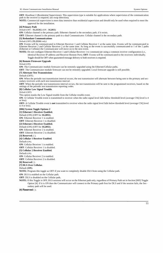
[005] System Toggle Options[1] Ethernet Receiver 1 SupervisedDefault (OFF)(TL2553G only).ON: Ethernet Receiver 1 will be supervised and heartbeats will be sent to Ethernet Receiver 1 based on the supervision interval pro-grammed in Section [004].OFF: Ethernet Receiver 1 will not be supervised. When disabled, heartbeat 1 is sent to the Ethernet receiver once every hour, regardlessof supervision type (heartbeat 1 or 2). The heartbeat is resent every 5 seconds until ACK. If no event or heartbeat ACK is received after(Receiver Supervision Interval + 75 seconds), Supervisory trouble is indicated.NOTE: Ethernet Receiver 2 can not be supervised.
[2] Cellular Receiver 1 SupervisedDefault (OFF)ON: Cellular Receiver 1 will be supervised and heartbeats will be sent to Cellular Receiver 1 based on the supervision interval pro-grammed in Section [004]. If ACK to heartbeat is not received, it is retransmitted every 5 seconds. Failure to ACK 2 consecutive heart-beats will reset the radio.OFF: Cellular Receiver 1 will not be supervised. When disabled, heartbeat is not sent to the receiver. Supervisory trouble is indicated.NOTE: Cellular Receiver 2 can not be supervised.
[3] Supervision TypeDefault (OFF)ON: Heartbeat 1 (Commercial Supervision). This supervision type is suitable for applications where swap detection is required on thesupervisory packet.
1.
ETHERNET/CELLULAR PROGRAMMING OPTIONS
3G Alarm Communicator Installation Manual System Options
11
OFF: Heartbeat 2 (Residential Supervision). This supervision type is suitable for applications where supervision of the communicationpath to the receiver is required. (no swap detection).NOTE: Commercial supervision is more data intensive than residential supervision and should only be used when required to meet the
approval for the installation.
[4] Primary PathDefault (OFF - TL2553G) (ON - 3G2055)ON: Cellular channel is the primary path. Ethernet channel is the secondary path, if it exists.OFF: Ethernet channel is the primary path in a dual Communicator. Cellular channel is the secondary path.[5] Redundant Communications Default (OFF) (TL2553G only)ON: Events will be communicated to Ethernet Receiver 1 and Cellular Receiver 1 at the same time. Events will be communicated toEthernet Receiver 2 and Cellular Receiver 2 at the same time. As long as the event is successfully communicated to 1 of the 2 paths(Ethernet or Cellular) the Communicator will move on to the next event.NOTE: Do not configure Ethernet Receiver 1 and Cellular Receiver 1 to communicate using a common receiver configuration (i.e.,
identical Receiver IP address and Receiver Remote Port). OFF: Events will be communicated to the receivers individually.Toggle should be OFF when guaranteed message delivery to both receivers is required.
[6] Remote Firmware UpgradeDefault (ON)ON: The Communicator module firmware can be remotely upgraded using the Ethernet/Cellular paths.OFF: The Communicator module firmware can not be remotely upgraded. Local firmware upgrade is still possible.[7] Alternate Test TransmissionsDefault (OFF).ON: When the periodic test transmission interval occurs, the test transmission will alternate between being sent to the primary and sec-ondary receivers with each test transmission interval.OFF: When the periodic test transmission interval occurs, the test transmission will be sent to the programmed receivers, based on thesettings of the periodic test transmission reporting codes.[8] Cellular Low Signal Trouble.Default (OFF)This option masks the Low Signal trouble from the Cellular trouble event.ON: A Cellular Trouble event is transmitted to receiver when the radio signal level falls below threshold level (average CSQ level is 4or less).OFF: A Cellular Trouble event is not transmitted to receiver when the radio signal level falls below threshold level (average CSQ levelis 4 or less).
[006] System Toggle Options 2[1] Ethernet 1 Receiver Enabled.Default (ON) (OFF for 3G2055).ON: Ethernet Receiver 1 is enabled.OFF: Ethernet Receiver 1 is disabled.[2] Ethernet 2 Receiver Enabled.Default (ON) (OFF for 3G2055).ON: Ethernet Receiver 2 is enabled.OFF: Ethernet Receiver 2 is disabled.[3] Reserved. ( ).[4] Cellular 1 Receiver Enabled.Default (ON).
ON: Cellular Receiver 1 is enabled. OFF: Cellular Receiver 1 is disabled.[5] Cellular 2 Receiver Enabled.Default (ON).
ON: Cellular Receiver 2 is enabled.OFF: Cellular Receiver 2 is disabled.[6] Reserved ( ).[7] DLS Over Cellular.Default (ON).NOTE: Program this toggle as OFF if you want to completely disable DLS from using the Cellular path.
ON: DLS is enabled on the Cellular path.OFF: DLS is disabled on the Cellular path.NOTE: If this Toggle is OFF, DLS sessions will occur on the Ethernet path only, regardless of Primary Path set in Section [005] Toggle
Option [4]. If it is ON then the Communicator will connect to the Primary path first for DLS and if the session fails, the Sec-ondary path will be used.
[8] Reserved ( ).
Programming Options 3G Alarm Communicator Installation Manual
12
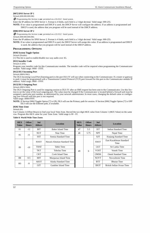
[007] DNS Server IP 1Default (000.000.000.000)
Programming this Section is not permitted on a UL/ULC listed system.Enter the IP address for DNS Server 1. Format is 4 fields, each field is a 3 digit decimal. Valid range: 000-255.NOTE: If no value is programmed and DHCP is used, the DHCP Server will configure the address. If an address is programmed and
DHCP is used, the address that you program will be used instead of the DHCP address.
[008] DNS Server IP 2 Programming this Section is not permitted on a UL/ULC listed system.Default (000.000.000.000)Enter the IP address for DNS Server 2. Format is 4 fields, each field is a 3 digit decimal. Valid range: 000-255.NOTE: If no value is programmed and DHCP is used, the DHCP Server will assign this value. If an address is programmed and DHCP
is used, the address that you program will be used instead of the DHCP address.
PROGRAMMING OPTIONS
[010] System Toggle OptionDefault (Disable)[1] This bit is used to enable/disable two way audio over 3G.
[011] Installer CodeDefault (CAFE)Program your installer code for this Communicator module. The installer code will be required when programming the Communicatormodule. Valid range: 0000 - FFFF.
[012] DLS Incoming PortDefault (0BF6/3062)The DLS Incoming Local Port (listening port) is the port DLS IV will use when connecting to the Communicator. If a router or gatewayis used, it must be programmed with a Transmission Control Protocol (TCP) port forward for this port to the Communicator module IPaddress. Valid range: 0000 - FFFF.
[013] DLS Outgoing PortDefault (0BFA/3066)The DLS Outgoing Port is used for outgoing session to DLS IV after an SMS request has been sent to the Communicator. Use this Sec-tion to set the value of the local outgoing port. The value must be changed if the Communicator is located behind a firewall and must beassigned a particular port number, as determined by your network administrator. In most cases, changing the default value or configur-ing your firewall with this port is not required. Valid range: 0000-FFFF.NOTE: If Section [006] Toggle Option [7] is ON, DLS will use the Primary path for session. If Section [006] Toggle Option [7] is OFF
DLS will use the Ethernet path, if available.
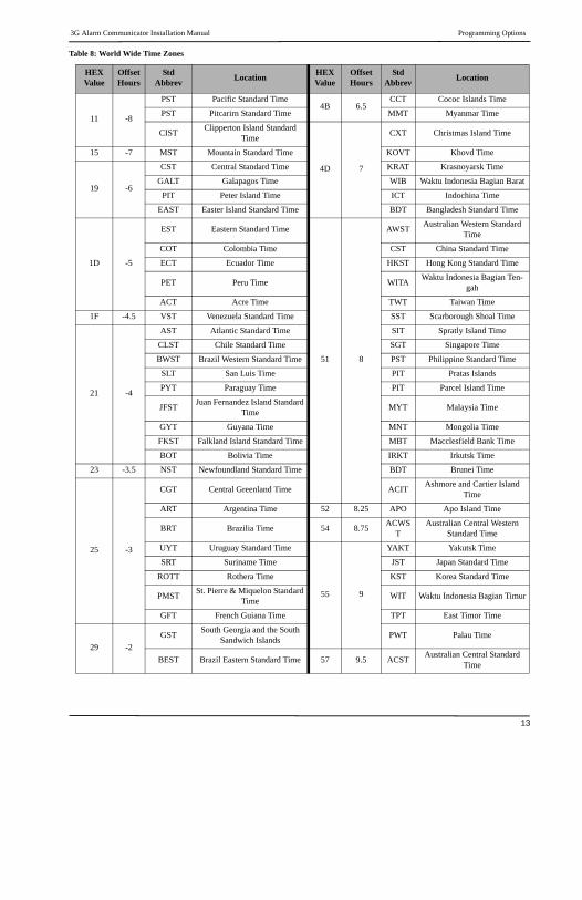
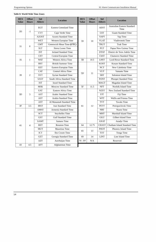
[020] Time ZoneDefault (00)Use Column 2 (Offset Hours) to find your local Time Zone. Record the two digit HEX value from Column 1 (HEX Value) on the same row. Program this HEX value for your Time Zone. Valid range is 00 - FF.
Table 8: World Wide Time Zones
HEXValue
OffsetHours
StdAbbrev
LocationHEXValue
OffsetHours
StdAbbrev
Location
01 -12 BIT Baker Island Time 47 5.5 IST Indian Standard Time
05 -11NUT Niue Time 48 5.75 NPT Nepal Time
SST Somoa Standard Time
49 6
XJT Xinjiang Standard Time
09 -10
HAST Hawaii-Aleutian Standard Time EKSTEast Kazakhstan Standard
Time
THAT Tahiti Time LKT Sri Lanka Time
TKT Tokelau Time VOST Vostok Time
CKT Cook Island Time OMSK Omsk Standard Time
0B -9.5 MIT Marquesas Island Time NOVT Novosibirsk Time
0D -9AKST Alaska Standard Time BTT Bhutan Time
GIT Gambier Island Time BIOT British Indian Ocean Time
3G Alarm Communicator Installation Manual Programming Options
13
11 -8
PST Pacific Standard Time4B 6.5
CCT Cococ Islands Time
PST Pitcarirn Standard Time MMT Myanmar Time
CISTClipperton Island Standard
Time
4D 7
CXT Christmas Island Time
15 -7 MST Mountain Standard Time KOVT Khovd Time
19 -6
CST Central Standard Time KRAT Krasnoyarsk Time
GALT Galapagos Time WIB Waktu Indonesia Bagian Barat
PIT Peter Island Time ICT Indochina Time
EAST Easter Island Standard Time BDT Bangladesh Standard Time
1D -5
EST Eastern Standard Time
51 8
AWSTAustralian Western Standard
Time
COT Colombia Time CST China Standard Time
ECT Ecuador Time HKST Hong Kong Standard Time
PET Peru Time WITAWaktu Indonesia Bagian Ten-
gah
ACT Acre Time TWT Taiwan Time
1F -4.5 VST Venezuela Standard Time SST Scarborough Shoal Time
21 -4
AST Atlantic Standard Time SIT Spratly Island Time
CLST Chile Standard Time SGT Singapore Time
BWST Brazil Western Standard Time PST Philippine Standard Time
SLT San Luis Time PIT Pratas Islands
PYT Paraguay Time PIT Parcel Island Time
JFSTJuan Fernandez Island Standard
TimeMYT Malaysia Time
GYT Guyana Time MNT Mongolia Time
FKST Falkland Island Standard Time MBT Macclesfield Bank Time
BOT Bolivia Time IRKT Irkutsk Time
23 -3.5 NST Newfoundland Standard Time BDT Brunei Time
25 -3
CGT Central Greenland Time ACITAshmore and Cartier Island
Time
ART Argentina Time 52 8.25 APO Apo Island Time
BRT Brazilia Time 54 8.75ACWS
TAustralian Central Western
Standard Time
UYT Uruguay Standard Time
55 9
YAKT Yakutsk Time
SRT Suriname Time JST Japan Standard Time
ROTT Rothera Time KST Korea Standard Time
PMSTSt. Pierre & Miquelon Standard
TimeWIT Waktu Indonesia Bagian Timur
GFT French Guiana Time TPT East Timor Time
29 -2
GSTSouth Georgia and the South
Sandwich IslandsPWT Palau Time
BEST Brazil Eastern Standard Time 57 9.5 ACSTAustralian Central Standard
Time
Table 8: World Wide Time Zones
HEXValue
OffsetHours
StdAbbrev
LocationHEXValue
OffsetHours
StdAbbrev
Location
Programming Options 3G Alarm Communicator Installation Manual
14
2D -1
EGT Eastern Greenland Time
59 10
AESTAustralian Eastern Standard
Time
CVT Cape Verde Time GST Guam Standard Time
AZOST Azores Standard Time YAPT Yap Time
31 0
WET Western Europian Time VLAT Vladivostok Time
GMT Greenwich Mean Time (UTC) TRUT Truk Time
SLT Sierra Leone Time PGT Papua New Guinea Time
IST Ireland Standard Time DTAT District de Terre Adelie Time
35 1
CET Central Europian Time ChST Chamorro Standard Time
WAT Western Africa Time 5B 10.5 LHST Lord Howe Standard Time
BST British Summer Time
5D 11
KOST Kosare Standard Time
39 2
EET Eastern Europian Time NCT New Caledonia Time
CAT Central Africa Time VUT Vanuatu Time
SYT Syrian Standard Time SBT Solomon Island Time
SAST South Africa Standard Time PONT Phonpei Standard Time
IST Israel Standard Time MAGT Magadan Island Time
3D 3
MSK Moscow Standard Time 5F 11.5 NFT Norfolk Island Time
EAT Eastern Africa Time
61 12
NZST New Zealand Standard Time
AST Arabic Standard Time FJT Fiji Time
AST Arabia Standard Time WFT Wallis and Futuna Time
AST Al Manamah Standard Time TVT Tuvalu Time
3F 3.5 IRST Iran Standard Time PETT Petropavlovsk Time
41 4
AMST Armenia Standard Time NRT Nauru Time
SCT Seychelles Time MHT Marshall Island Time
GST Gulf Standard Time GILT Gilbert Island Time
SAMT Samara Time ANAT Anadyr Time
RET Reunion Time 64 12.75 CHAST Chatham Island Standard Time
MUT Mauritius Time65 13
PHOT Phoenix Island Time
ICT Iles Crozet Time TOT Tonga Time
GET Georgia Standard Time 69 14 LINT Line Island Time
AZT Azerbaijan Time 70 - FF N/A Reserved
43 4.5 AFT Afghanistan Time
Table 8: World Wide Time Zones
HEXValue
OffsetHours
StdAbbrev
LocationHEXValue
OffsetHours
StdAbbrev
Location

3G Alarm Communicator Installation Manual Communications Reporting Codes
15
[021] Account CodeDefault (FFFFFF)The account code is included when transmitting any events generated by the Communicator. (e.g., Panel Absent Trouble). It is recom-mended that the account code be the same as the control panel account number. Valid range: 000001-FFFFFE. If 4 digit account codesare needed the 2 lowest digits shall be programmed as FF.(e.g., Account 1234 is programmed as:1234FF).NOTE: Programming this Section with all 0 or F will cause a Module Configuration Trouble.
[022] Communications FormatDefault (04)Program 03 for Contact ID (CID). Program 04 for SIA. The module can be configured to send Events in SIA or CID format. The SIAcommunication format follows the level 2 specifications of the SIA Digital Communication Standard - October 1997. This format willsend the account code along with its data transmission. The transmission will look similar to the following at the receiver. Example:Nri0 ET001Where: N = New Event; ri0 = Partition/Area identifier; ET = Panel Absent Trouble; 001 = Zone 001.
COMMUNICATIONS REPORTING CODES
[023] Panel Absent TroubleDefault (FF)Program 00 to disable this event or FF to enable. This event will occur when communications with the panel have been lost for morethan 60 seconds.
[024] Panel Absent Trouble RestoreDefault (FF)Program 00 to disable this event or FF to enable. This event will occur when communications with the control panel have resumed.
[025] Radio Activation RestoreDefault (FF)Program 00 to disable this event or FF to enable. This event will occur after any successful Connect24 programming session.
45 5
CAST Chinese Atlantic Standard Time
WKST West Kazakhstan Standard Time
PKT Pakistan Time
YEKT Yekaterinburg Time
UZT Uzbekistan Time
TMT Turkmenistan Time
TJT Tajikistan Time
TFTFrench Southern and Antarctic
Time
MVT Maldives Time
MAWT Mawson Time
KGT Kyrgyzstan Time
HMTHeard and McDonald Island
Time
DAVT Davis Time
Table 9: Communications Reporting Codes
Event SIA Identifier
SIA Reporting
Code
CIDQualifier
CID Event Code
CID Reporting
Code
CID User/Zone
[023] Panel Absent Trouble ET 001 1 3 55 001
[024] Panel Absent Trouble Restore ER 001 3 3 55 001
[025] Radio Activation Restore RS 001 3 5 52 001
[026] Ethernet 1 Test Transmission RP 001 1 6 A3 951
[027] Ethernet 2 Test Transmission RP 002 1 6 A3 952
[028] Cellular 1 Test Transmission RP 003 1 6 A3 955
[029] Cellular 2 Test Transmission RP 004 1 6 A3 956
[030] FTC Restore YK 001 3 3 54 001
Table 8: World Wide Time Zones
HEXValue
OffsetHours
StdAbbrev
LocationHEXValue
OffsetHours
StdAbbrev
Location
System Test Options [026 - 029] 3G Alarm Communicator Installation Manual
16
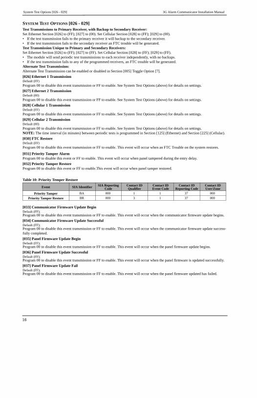
SYSTEM TEST OPTIONS [026 - 029]Test Transmissions to Primary Receiver, with Backup to Secondary Receiver:Set Ethernet Section [026] to (FF); [027] to (00). Set Cellular Section [028] to (FF); [029] to (00).• If the test transmission fails to the primary receiver it will backup to the secondary receiver.• If the test transmission fails to the secondary receiver an FTC trouble will be generated.Test Transmission Unique to Primary and Secondary Receivers:Set Ethernet Section [026] to (FF); [027] to (FF). Set Cellular Section [028] to (FF); [029] to (FF).• The module will send periodic test transmissions to each receiver independently, with no backups.• If the test transmission fails to any of the programmed receivers, an FTC trouble will be generated.Alternate Test Transmission:Alternate Test Transmission can be enabled or disabled in Section [005] Toggle Option [7].
[026] Ethernet 1 TransmissionDefault (FF)Program 00 to disable this event transmission or FF to enable. See System Test Options (above) for details on settings.
[027] Ethernet 2 TransmissionDefault (00)Program 00 to disable this event transmission or FF to enable. See System Test Options (above) for details on settings.
[028] Cellular 1 TransmissionDefault (FF)Program 00 to disable this event transmission or FF to enable. See System Test Options (above) for details on settings.
[029] Cellular 2 TransmissionDefault (00)Program 00 to disable this event transmission or FF to enable. See System Test Options (above) for details on settings.NOTE: The time interval (in minutes) between periodic tests is programmed in Section [125] (Ethernet) and Section [225] (Cellular).
[030] FTC RestoreDefault (FF)Program 00 to disable this event transmission or FF to enable. This event will occur when an FTC Trouble on the system restores.
[031] Priority Tamper AlarmProgram 00 to disable this event or FF to enable. This event will occur when panel tampered during the entry delay.
[032] Priority Tamper RestoreProgram 00 to disable this event or FF to enable.This event will occur when panel tamper restored.
[033] Communicator Firmware Update BeginDefault (FF);Program 00 to disable this event transmission or FF to enable. This event will occur when the communicator firmware update begins.
[034] Communicator Firmware Update SuccessfulDefault (FF);Program 00 to disable this event transmission or FF to enable. This event will occur when the communicator firmware update success-fully completed.
[035] Panel Firmware Update BeginDefault (FF);Program 00 to disable this event transmission or FF to enable. This event will occur when the panel firmware update begins.
[036] Panel Firmware Update SuccessfulDefault (FF);Program 00 to disable this event transmission or FF to enable. This event will occur when the panel firmware is updated successfully.
[037] Panel Firmware Update FailDefault (FF);Program 00 to disable this event transmission or FF to enable. This event will occur when the panel firmware updated has failed.
Table 10: Priority Temper Restore
Event SIA Identifier SIA Reporting Code
Contact ID Qualifier
Contact ID Event Code
Contact ID Reporting Code
Contact ID User/Zone
Priority Tamper BA 000 1 1 37 000
Priority Tamper Restore BR 000 3 1 37 000

3G Alarm Communicator Installation Manual Ethernet Receiver 1 Options
17
Table 11: Panel Tamper Alarm Restore
ETHERNET RECEIVER 1 OPTIONS
[101] Ethernet Receiver 1 Account CodeDefault (0000000000)The account code is used by the central station to distinguish between transmitters. This account code is used when transmitting heart-beat signals to the central station receiver. Signals received from the Panel will use the control panel account number. Valid range:0000000001-FFFFFFFFFE. Programming all 0 or all F will cause a Module Configuration Trouble.NOTE: If Ethernet Receiver 1 and Cellular Receiver 1 are programmed as the same receiver (IP and port number are identical), Ether-
net Receiver 1 account code will be used.
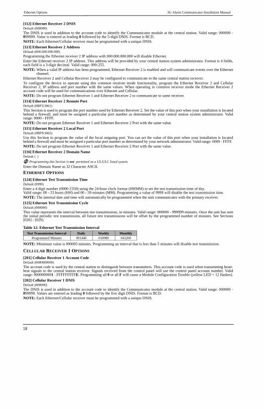
[102] Ethernet Receiver 1 DNISDefault (000000)The Dialled Number Information Service (DNIS) is used in addition to the Account Code to identify the Communicator module at thecentral station. Valid range: 000000 - 099999. Value is entered as a leading 0 followed by the 5 digit DNIS. Format is Binary CodedDecimal (BCD).NOTE: Each Ethernet/Cellular receiver must be programmed with a unique DNIS.
[103] Ethernet Receiver 1 AddressDefault (127.000.000.001)The default address enables the Communicator to operate in Unattended Mode.Unattended Mode is used when a receiver is not available and the unit is required to perform DLS sessions. Typically used where thecustomer programs the control panel daily due to access control and still wants to receive alarms without buying extra hardware(receiver) or software.NOTE: When a valid IP address has been programmed, Ethernet Receiver 1 is enabled and will communicate events over the Ethernet
channel.Ethernet Receiver 1 and Cellular Receiver 1 may be configured to communicate to the same central station receiver. To configure thedevice to operate using this Common Receiver Mode functionality, program Ethernet Receiver 1 and Cellular Receiver 1, IP addressand port number with identical values.NOTE: When operating in Common Receiver Mode, Ethernet Receiver 1 account code will be used for Ethernet and Cellular.
[104] Ethernet Receiver 1 Remote PortDefault (0BF5/3061)This Section determines the remote port of Ethernet receiver 1. Valid range: 0000 - FFFF.
[105] Ethernet Receiver 1 Local PortDefault (0BF4/3060)Use this Section to set the value of the local outgoing port. Set the value of this port when your installation is located behind a firewalland must be assigned a particular port number as determined by your central station system administrator. Valid range: 0000 - FFFF.
[106] Ethernet Receiver 1 Domain NameDefault ( )Enter the Domain Name as 32 ASCII characters. Programming this Section is not permitted on a UL/ULC listed system.
ETHERNET RECEIVER 2 OPTIONS
[111] Ethernet Receiver 2 Account CodeDefault (0000000000)The account code is used by the central station to distinguish between transmitters. The account code is used when transmitting heart-beat signals to the central station receiver. Signals received from the control panel will use the control panel account number. Validrange: 0000000001- FFFFFFFFFE. Programming all 0 or all F will cause a Module Configuration Trouble (yellow LED=12 flashes).NOTE: If both Ethernet Receiver 2 and Cellular Receiver 2 are the same receiver (IP and port number are identical), Ethernet Receiver
2 account will be used for Ethernet and Cellular.
EventSIA
Identifier
SIA Reporting
Code
Contact IDQualifier
Contact IDEvent Code
Contact IDReporting
Code
Contact IDUser/Zone
[033]Comm. FW Update Begin
LB 00 1 9 03 002
[034]Comm. FW Update Suc-cessful
LS 00 3 9 03 002
[035]Panel FW Update Begin LB 00 1 9 03 003
[036]Panel FW Update Suc-cessful
LS 00 3 9 03 003
[037]Panel FW Update Fail LU 00 1 9 04 003
Ethernet Options 3G Alarm Communicator Installation Manual
18
[112] Ethernet Receiver 2 DNISDefault (000000)The DNIS is used in addition to the account code to identify the Communicator module at the central station. Valid range: 000000 -099999. Value is entered as leading 0 followed by the 5-digit DNIS. Format is BCD.NOTE: Each Ethernet/Cellular receiver must be programmed with a unique DNIS.
[113] Ethernet Receiver 2 AddressDefault (000.000.000.000)Programming the Ethernet receiver 2 IP address with 000.000.000.000 will disable Ethernet.Enter the Ethernet receiver 2 IP address. This address will be provided by your central station system administrator. Format is 4 fields,each field is a 3-digit decimal. Valid range: 000-255.NOTE: When a valid IP address has been programmed, Ethernet Receiver 2 is enabled and will communicate events over the Ethernet
channel.Ethernet Receiver 2 and Cellular Receiver 2 may be configured to communicate to the same central station receiver.To configure the device to operate using this common receiver mode functionality, program the Ethernet Receiver 2 and CellularReceiver 2, IP address and port number with the same values. When operating in common receiver mode the Ethernet Receiver 2account code will be used for communications over Ethernet and Cellular.NOTE: Do not program Ethernet Receiver 1 and Ethernet Receiver 2 to communicate to same receiver.
[114] Ethernet Receiver 2 Remote PortDefault (0BF5/3061)This Section is used to program the port number used by Ethernet Receiver 2. Set the value of this port when your installation is locatedbehind a firewall, and must be assigned a particular port number as determined by your central station system administrator. Validrange: 0000 - FFFF.NOTE: Do not program Ethernet Receiver 1 and Ethernet Receiver 2 Port with the same value.
[115] Ethernet Receiver 2 Local PortDefault (0BF9/3065)Use this Section to program the value of the local outgoing port. You can set the value of this port when your installation is locatedbehind a firewall and must be assigned a particular port number as determined by your network administrator. Valid range: 0000 - FFFF. NOTE: Do not program Ethernet Receiver 1 and Ethernet Receiver 2 Port with the same value.
[116] Ethernet Receiver 2 Domain NameDefault ( )
Programming this Section is not permitted on a UL/ULC listed system.Enter the Domain Name as 32 Character ASCII.
ETHERNET OPTIONS
[124] Ethernet Test Transmission TimeDefault (9999)Enter a 4 digit number (0000-2359) using the 24-hour clock format (HHMM) to set the test transmission time of day. Valid range: 00 - 23 hours (HH) and 00 - 59 minutes (MM). Programming a value of 9999 will disable the test transmission time.NOTE: The internal date and time will automatically be programmed when the unit communicates with the primary receiver.
[125] Ethernet Test Transmission CycleDefault (000000)This value represents the interval between test transmissions, in minutes. Valid range: 000000 - 999999 minutes. Once the unit has sentthe initial periodic test transmission, all future test transmissions will be offset by the programmed number of minutes. See Sections[026] - [029].
NOTE: Minimum value is 000005 minutes. Programming an interval that is less than 5 minutes will disable test transmission.
CELLULAR RECEIVER 1 OPTIONS
[201] Cellular Receiver 1 Account CodeDefault (0000000000)The account code is used by the central station to distinguish between transmitters. This account code is used when transmitting heart-beat signals to the central station receiver. Signals received from the control panel will use the control panel account number. Validrange: 0000000001 - FFFFFFFFFE. Programming all 0 or all F will cause a Module Configuration Trouble (yellow LED = 12 flashes).
[202] Cellular Receiver 1 DNISDefault (000000)The DNIS is used in addition to the account code to identify the Communicator module at the central station. Valid range: 000000 -099999. Values are entered as leading 0 followed by the five digit DNIS. Format is BCD.NOTE: Each Ethernet/Cellular receiver must be programmed with a unique DNIS.
Table 12: Ethernet Test Transmission Interval
Test Transmission Interval Daily Weekly MonthlyProgrammed Minutes 001440 010080 043200
3G Alarm Communicator Installation Manual Cellular Receiver 2 Options
19
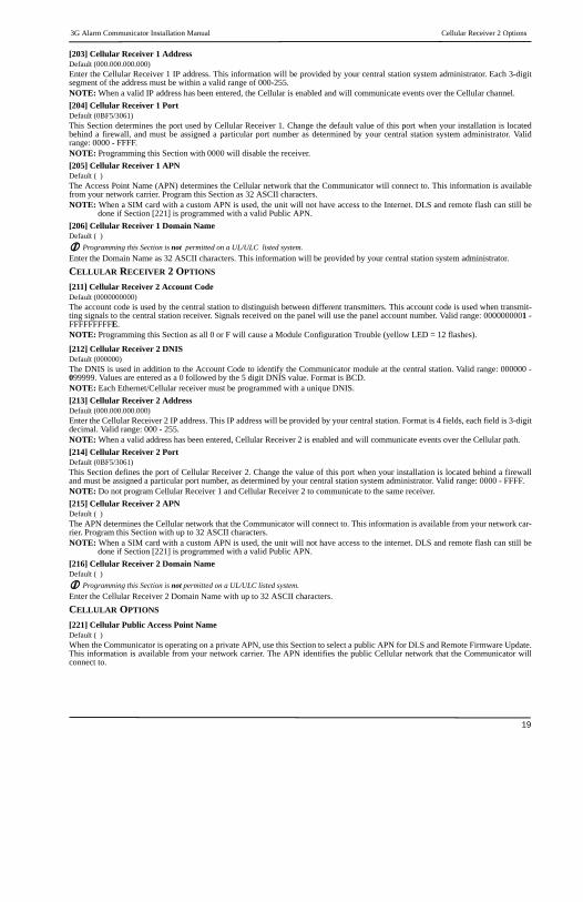
[203] Cellular Receiver 1 AddressDefault (000.000.000.000)Enter the Cellular Receiver 1 IP address. This information will be provided by your central station system administrator. Each 3-digitsegment of the address must be within a valid range of 000-255.NOTE: When a valid IP address has been entered, the Cellular is enabled and will communicate events over the Cellular channel.
[204] Cellular Receiver 1 PortDefault (0BF5/3061)This Section determines the port used by Cellular Receiver 1. Change the default value of this port when your installation is locatedbehind a firewall, and must be assigned a particular port number as determined by your central station system administrator. Validrange: 0000 - FFFF.NOTE: Programming this Section with 0000 will disable the receiver.
[205] Cellular Receiver 1 APNDefault ( )The Access Point Name (APN) determines the Cellular network that the Communicator will connect to. This information is availablefrom your network carrier. Program this Section as 32 ASCII characters.NOTE: When a SIM card with a custom APN is used, the unit will not have access to the Internet. DLS and remote flash can still be
done if Section [221] is programmed with a valid Public APN.
[206] Cellular Receiver 1 Domain NameDefault ( )
Programming this Section is not permitted on a UL/ULC listed system.Enter the Domain Name as 32 ASCII characters. This information will be provided by your central station system administrator.
CELLULAR RECEIVER 2 OPTIONS
[211] Cellular Receiver 2 Account CodeDefault (0000000000)The account code is used by the central station to distinguish between different transmitters. This account code is used when transmit-ting signals to the central station receiver. Signals received on the panel will use the panel account number. Valid range: 0000000001 -FFFFFFFFFE. NOTE: Programming this Section as all 0 or F will cause a Module Configuration Trouble (yellow LED = 12 flashes).
[212] Cellular Receiver 2 DNISDefault (000000)The DNIS is used in addition to the Account Code to identify the Communicator module at the central station. Valid range: 000000 -099999. Values are entered as a 0 followed by the 5 digit DNIS value. Format is BCD.NOTE: Each Ethernet/Cellular receiver must be programmed with a unique DNIS.
[213] Cellular Receiver 2 AddressDefault (000.000.000.000)Enter the Cellular Receiver 2 IP address. This IP address will be provided by your central station. Format is 4 fields, each field is 3-digitdecimal. Valid range: 000 - 255.NOTE: When a valid address has been entered, Cellular Receiver 2 is enabled and will communicate events over the Cellular path.
[214] Cellular Receiver 2 PortDefault (0BF5/3061)This Section defines the port of Cellular Receiver 2. Change the value of this port when your installation is located behind a firewalland must be assigned a particular port number, as determined by your central station system administrator. Valid range: 0000 - FFFF.NOTE: Do not program Cellular Receiver 1 and Cellular Receiver 2 to communicate to the same receiver.
[215] Cellular Receiver 2 APNDefault ( )The APN determines the Cellular network that the Communicator will connect to. This information is available from your network car-rier. Program this Section with up to 32 ASCII characters.NOTE: When a SIM card with a custom APN is used, the unit will not have access to the internet. DLS and remote flash can still be
done if Section [221] is programmed with a valid Public APN.
[216] Cellular Receiver 2 Domain NameDefault ( )
Programming this Section is not permitted on a UL/ULC listed system.Enter the Cellular Receiver 2 Domain Name with up to 32 ASCII characters.
CELLULAR OPTIONS
[221] Cellular Public Access Point NameDefault ( )When the Communicator is operating on a private APN, use this Section to select a public APN for DLS and Remote Firmware Update.This information is available from your network carrier. The APN identifies the public Cellular network that the Communicator willconnect to.

Command and Control Options 3G Alarm Communicator Installation Manual
20
[222] Cellular Login User NameDefault ( )Some network carriers require you to provide login credentials when connecting to an APN. Program your login User Name in this Sec-tion. Format is up to 32 ASCII characters.NOTE: This Section is not accessible via SCW keypad programming.
[223] Cellular Login PasswordDefault ( )Some network carriers require you to provide login credentials when connecting to an APN. Program your login Password in this Sec-tion.Format is up to 32 ASCII characters.
[224] Cellular Test Transmission Time of DayDefault (9999)Enter a 4 digit value using the 24-hour clock format (HHMM) to set the test transmission time of day. Valid range: 00-23 for the hours(HH) and 00-59 for the minutes (MM).NOTE: To disable the test transmission time of day enter 9999 or FFFF in this Section.
The internal date and time will be automatically programmed by the primary receiver only.
[225] Cellular Test Transmission Cycle Default (000000)This value represents the interval in between test transmissions in minutes. Valid range: 000000 - 999999 minutes. Once the unit hassent the initial periodic test transmission, all future test transmissions will be offset by the programmed number of minutes. See Sec-tions [026] - [029].
NOTE: Minimum value is 000005 minutes. Programming an interval that is less than 5 minutes will disable test transmission.
[226] Cellular Trouble DelayDefault (00)This option is used to program the delay, in minutes, for reporting a Cellular Trouble Delay. Valid entries are 00 - FF. (e.g., for a 10 min-ute Cellular Trouble Delay enter: 0A). There is no reporting delay if value is programmed as 00.
[227] Voice Call TimeoutDefault (00);This option sets the Voice Call Timeout, in minutes. Programming a value of 00 will disable timeout. Valid range is 00 to FF.[228] Voice Call Back TimeDefault (0A);This option sets the Voice call back time, in minutes. When the Communicator requests Call Back from the receiver, it will answerincoming calls during the programmed timeout period. If an incoming call is received after the timeout from requesting call back, theCommunicator will answer the call and immediately hang up. Programming a value of 00 will disable timeout (accept all incomingcalls). Default value is 0A/10 seconds. Valid range is 00 to FF.[229] Voice Call Back NumberDefault (SIM Telephone Number);This option sets the Voice Call Back Telephone Number for the receiver. This number is used for Two Way calling. Current SIM tele-phone number can be viewed in Section [996]. Valid entry is 32 character ASCII.
COMMAND AND CONTROL OPTIONS
[301] Command and Control Toggle Options[1] SMS Notification Default (ON).[2] Reserved Default ( ).
[3] SMS Command and Control Default (ON).[4] Reserved Default ( ).[5] SMS Character Format Default.
ON: SMS Unicode, maximum message length is 70 characters.OFF: 7 bit SMS, maximum message length is 160 characters.
[6] Long SMS Message Handling Default (OFF).ON: If longer than maximum message length, it is split and sent as multiple SMS messages.OFF: If longer than maximum message length, a single, truncated SMS message is sent.
[7-8] Reserved Default ( ).
Table 13: Cellular Test Transmission Interval
Test Transmission Interval Daily Weekly MonthlyProgrammed Minutes 001440 010080 043200

3G Alarm Communicator Installation Manual SMS Command and Control Functions
21
[311] - [318] SMS Phone Number 1 - 8Default ( );These Sections may be programmed through DLS IV or the keypad. Up to 8 SMS telephone numbers (4 - 32 digits) can be pro-grammed in Section [31x] Where x is an SMS telephone number from 1 to 8. Leaving programming blank for a telephone number will disable that number. The User can program their own mobile telephone numbers at the keypad using [*] [6] <> “SMS Programming”. The SMS Command and Control feature utilizes the SMS messaging service provided by the Cellular network and is subject to the lim-itations of SMS messaging. These limitations include delayed messages and lack of guaranteed delivery.
NOTE: SMS Command and Control (Sections [601] - [618] will only process messages from the mobile telephone numbers pro-grammed in this Section if SMS Command and Control is enabled [301][ 3] ON. SMS responses are listed in Sections [621] - [630]. A blank telephone number is disabled.
SMS COMMAND AND CONTROL FUNCTIONS
Users can send SMS text messages from their mobile phone to the communicator cellular phone number assigned to their system. Com-mands are only accepted from telephone numbers that have been programmed in Sections [311]-[318]. The system will reject messages sent from telephone numbers that are not on the programmed list.When the received SMS text matches a valid Section message, the function is performed on the control panel. Text messages are not case sensitive and extra spaces are ignored. A User Access Code may be required for some SMS messages.The User can send just the partition number or the complete label.(e.g., “Away arm Partition 2 1234” is treated the same as “away arm 2 1234”).The SMS Message format is in 3 parts: Command, Partition Label (or only the partition number), and Access Code.• If an Access Code is included in the message, it is sent to the control panel for validation, along with the requested function.• If the panel is configured to require an Access Code and the code is not sent (or invalid) the panel will fail the function (unsuccess-
ful).• If the panel fails the function, an SMS response message is sent to the user. The SMS response will echo the command sent, followed
by the label “unsuccessful”. (e.g., “night arm partition 2 1234 unsuccessful”).• The partition label or partition number may be excluded from the SMS request in a single partition system (e.g., disarm 9123).
NOTE: The communicator cellular phone number can be viewed in Section [851], [996] and/or [851], [229] or by user entering [*][6], then scrolling down to ‘SMS Programming” and scrolling down to “Cellular phone No.” [<] [>] “Cellular Phone No.” at the keypad. An Access Code is required for all SMS commands, except Help.
[601] Stay ArmDefault (Stay Arm);Send this command to the system to stay arm. It may be followed by a Partition Label or partition number and Access Code.[602] Away ArmDefault (Away Arm);Send this command to the system to away arm. It may be followed by a Partition Label or partition number and Access Code.[603] Night ArmDefault (Night Arm);Send this command to the system to night arm. It may be followed by a Partition Label or partition number and Access Code.[604] DisarmDefault (Disarm);Send this command to the system to disarm. It may be followed by a Partition Label or partition number and Access Code.[605] - [608] Activate Command Output 1 - 4Default (Activate Command Output n);Where n is a number from 1 - 4. Send this command to the system to activate a command output. It may be followed by a Partition Label or partition number and Access Code. [609] - [612] Deactivate Command Output 1 - 4Default (Deactivate Command Output n);Where n is a number from 1 - 4. Send this command to the system to deactivate a command output. This command may be followed by a Partition Label or partition number and optional Access Code.[613] Bypass Default (Bypass);Send this command to the system to bypass a Zone. This command should be followed by a Zone label or Zone number and Access Code. [614] UnbypassDefault (Unbypass);Send this command to the system to unbypass a Zone. This command should be followed by the Zone label or Zone number and Access Code. [615] Status RequestDefault (Status Request);Send this command to request the status of the system. It may be followed by a partition label or partition number and Access Code. If partition label is omitted, status of all enabled partitions will be sent. If there is a trouble on the system, the system label is sent, fol-lowed by the trouble label, then the partition status.
NOTE: Status Request response may require more than one SMS message, depending on status of the system. There is a 10-second delay between transmission of SMS messages.

SMS Command and Control Response 3G Alarm Communicator Installation Manual
22
[616] Alarm Memory RequestDefault (Alarm Memory Request);Send this command to the system to request the alarm memory from the system. This command may be followed by a Partition Label or partition number, and Access Code. If partition label is omitted, alarm memory of all partitions will be sent. Alarm memory responses will include Partition label and Zone label. Up to 8 partitions may be contained in 1 message.
NOTE: Alarm Memory Request response may require more than one SMS message, depending on alarm memory of the unit. There is a 10-second delay between transmission of SMS messages.
[617] HelpDefault (Help);When help is sent, the SMS response is a listing of all interactive commands that can be sent to the module. Access Code is not required.[619] Keypad MessageDefault (Keypad Message);The response format is: [Account Label] [Date and Time] [SMS Function] [Response] [Message Text]. Fields are space delim-ited.When Keypad Message is sent, the SMS response is the message displayed on the keypad. If the message is too long to display on the keypad, only the portion displayed is sent in the response.
SMS COMMAND AND CONTROL RESPONSE
NOTE: SMS Command and Control Response messages are up to 32 ASCII characters (Maximum 160 characters per SMS message). The message language is specified in Section [009]. SMS responses are sent to the phone that initiated the command.
[621] Function SuccessfulDefault (Successful);When an SMS Command and Control function is successfully performed by the panel, the successful label is included in the response sent to the user, following the command requested. (e.g., if “stay armed” command is completed by the panel, SMS response is: “stay armed successful”).[622] Function UnsuccessfulDefault (Unsuccessful);When an SMS Command and Control function is not successfully performed by the panel, the command sent to the unit will be included in the response sent to the user, followed by this label. (e.g., if “stay armed” command is not completed, SMS response is: “stay armed unsuccessful”).[623] Invalid CommandDefault (Invalid Command);This label will be included in the response message if the command was not accepted as a valid SMS command.[624] System Stay ArmedDefault (Stay Armed);This label will be included in the response to a status request command if a partition is stay armed.[625] System Away ArmedDefault (Away Armed);This label will be included in the response to a status request command if a partition is away armed.[626] System Night ArmedDefault (Night Armed);This label will be included in the response to a status request command if a partition is night armed.[627] System Disarmed ReadyDefault (Disarmed Ready);This label will be included in the response to a status request command if a partition is disarmed and is ready to arm.[628] System Disarmed Not ReadyDefault (Disarmed Not Ready);This label will be included in the response to a status request command if a partition is disarmed and is not ready to arm.[629] System is in AlarmDefault (is in Alarm);This label will be included in the response to a status request command if a partition is in alarm.[630] Trouble Label Default (Service is Required);This label will be included in the response to the Alarm Memory command if there are no alarms in memory.[631] No Alarms in MemoryDefault (No Alarm Memory);This label will be included in the response to an Alarm Memory Request if there are no alarms on the system.

3G Alarm Communicator Installation Manual SMS Command and Control Response
23
[634] Error CodeDefault (Error Code);When an SMS initiated function fails, the module will send an error code to the telephone number that was source of the SMS request. Message format is: [Account Label] [Date and Time] [Error Code] [Error Type]. Fields are “space” delimited.
Table 14: Error Code Format
Class Definition Error Definition
01 DLS
01 Bad SMS format
02 Session failed due to local network issues
03 Unable to connect to remote server
04 Bad DLS access code
05 DLS lockout active
02 TFTP
01 Bad SMS format
02 Session failed due to local network issues
03 Unable to connect to remote server
04 File not found on TFTP server
05 File not found on TFTP server
06 Update was unsuccessful
07 Update was successful
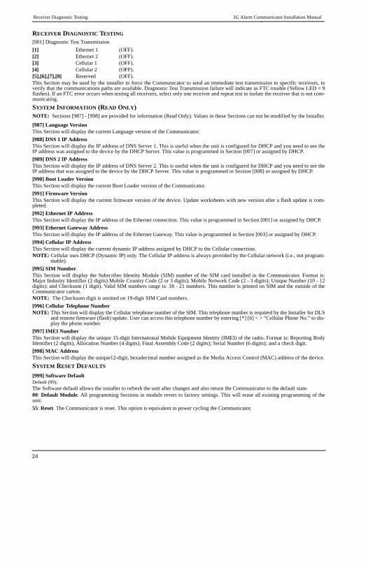
Receiver Diagnostic Testing 3G Alarm Communicator Installation Manual
24
RECEIVER DIAGNOSTIC TESTING
[901] Diagnostic Test Transmission
[1] Ethernet 1 (OFF).[2] Ethernet 2 (OFF).[3] Cellular 1 (OFF).[4] Cellular 2 (OFF).[5],[6],[7],[8] Reserved (OFF).This Section may be used by the installer to force the Communicator to send an immediate test transmission to specific receivers, toverify that the communications paths are available. Diagnostic Test Transmission failure will indicate as FTC trouble (Yellow LED = 9flashes). If an FTC error occurs when testing all receivers, select only one receiver and repeat test to isolate the receiver that is not com-municating.
SYSTEM INFORMATION (READ ONLY)NOTE: Sections [987] - [998] are provided for information (Read Only). Values in these Sections can not be modified by the Installer.
[987] Language VersionThis Section will display the current Language version of the Communicator.
[988] DNS 1 IP AddressThis Section will display the IP address of DNS Server 1. This is useful when the unit is configured for DHCP and you need to see theIP address was assigned to the device by the DHCP Server. This value is programmed in Section [007] or assigned by DHCP.
[989] DNS 2 IP AddressThis Section will display the IP address of DNS Server 2. This is useful when the unit is configured for DHCP and you need to see theIP address that was assigned to the device by the DHCP Server. This value is programmed in Section [008] or assigned by DHCP.
[990] Boot Loader VersionThis Section will display the current Boot Loader version of the Communicator.
[991] Firmware VersionThis Section will display the current firmware version of the device. Update worksheets with new version after a flash update is com-pleted.
[992] Ethernet IP AddressThis Section will display the IP address of the Ethernet connection. This value is programmed in Section [001] or assigned by DHCP.
[993] Ethernet Gateway Address This Section will display the IP address of the Ethernet Gateway. This value is programmed in Section [003] or assigned by DHCP.
[994] Cellular IP AddressThis Section will display the current dynamic IP address assigned by DHCP to the Cellular connection.NOTE: Cellular uses DHCP (Dynamic IP) only. The Cellular IP address is always provided by the Cellular network (i.e., not program-
mable).
[995] SIM NumberThis Section will display the Subscriber Identity Module (SIM) number of the SIM card installed in the Communicator. Format is:Major Industry Identifier (2 digits) Mobile Country Code (2 or 3 digits); Mobile Network Code (2 - 3 digits); Unique Number (10 - 12digits); and Checksum (1 digit). Valid SIM numbers range is: 18 - 21 numbers. This number is printed on SIM and the outside of theCommunicator carton.NOTE: The Checksum digit is omitted on 19-digit SIM Card numbers.
[996] Cellular Telephone NumberNOTE: This Section will display the Cellular telephone number of the SIM. This telephone number is required by the Installer for DLS
and remote firmware (flash) update. User can access this telephone number by entering [*] [6] < > “Cellular Phone No.” to dis-play the phone number.
[997] IMEI NumberThis Section will display the unique 15-digit International Mobile Equipment Identity (IMEI) of the radio. Format is: Reporting BodyIdentifier (2 digits), Allocation Number (4 digits); Final Assembly Code (2 digits); Serial Number (6 digits); and a check digit.
[998] MAC AddressThis Section will display the unique12-digit, hexadecimal number assigned as the Media Access Control (MAC) address of the device.
SYSTEM RESET DEFAULTS
[999] Software DefaultDefault (99);The Software default allows the installer to refresh the unit after changes and also return the Communicator to the default state.00: Default Module. All programming Sections in module revert to factory settings. This will erase all existing programming of theunit.
55: Reset. The Communicator is reset. This option is equivalent to power cycling the Communicator.

3G Alarm Communicator Installation Manual Communicator Troubleshooting
25
Communicator Troubleshooting[984] Communicator StatusThe communicator status sections are intended to provide the installer with real-time status of the communicator’s functionality, opera-tional readiness, failures, and potential malfunctions that may affect flawless operation of the communicator and its primary function ofsending signal to the central station in case the monitored event occurs.The communicator status is displayed in the form of a 6-digit CODE (6 hexadecimal numbers) as in the following pattern: 00000F. Therange of the code is from: 00000F – 2220CF. Not all numbers in this range are assigned a status code (Some numbers are skipped, i.e.not assigned the code).Each digit represents a status or trouble indicator (or assigned function when no trouble is present) as described below:
1. Digit 1 - Signal Indicator 1, displays the presence/strength of signal 1.
2. Digit 2 - Signal Indicator 2, displays the presence/strength of signal 2.
3. Digit 3 - Network Indicator, displays the presence (operational status) of network.
4. Digit 4 & 5 – TROUBLE INDICATOR displays the type of problem/malfunction on communicator or modules associated with andconnected to communicator.
5. Digit 6 – Reserved for future use.For example, status code 11002F – when interpreted means: “Signal Indicator 1 OK, Signal indicator 2 OK, there is no network trouble,and there is trouble in the communicator, Panel supervision trouble.” For details see the table below:
Table 15: Communicator Status and Trouble Coding in Hexadecimal Numbers
The communicator status codes will indicate the signal levels with digit 1 and 2, a network status with digit 3, and the trouble statuswith digit 4 and 5 as indicated in table above. For example status code 11000F would display following status:1 – On = Signal indicator 1, is ON1 – On = Signal indicator 2, is ON0 – OFF = Network indicator, network is working00 – TROUBLE INDICATOR = there is no trouble on the communicator.F – Future code not assigned yet. It is sixth hexadecimal digit. It could be also ‘ - ‘ (dash) instead of letter F (11000-).In this example both signal indicators are on indicating that communicator has excellent signal level; the network indicator is OFFshowing that we do not have any network problems and trouble indicators are both OFF indicating that we don’t have any trouble onthe communicator.
[985] Radio Initialization StatusThe radio initialization status is intended to provide the installer with real-time status of radio communication. The radio initializationstatus is displayed in an 8 bit toggle option. Each digit indicates one task in the radio initialization process as follows:
1. Radio power up
2. Received the SMS from C24
3. Radio reset
4. Radio attached to network
5. Receiver 1 Initialized
6. Receiver 2 Initialized
7. Receiver 3 Initialized
8. Receiver 4 InitializeThe following table shows each digit position in the status code, each digit’s value and its assigned meaning in the eight-digit code:
Digit 1 Digit 2 Digit 3 Digit 4 & 5 Digit 6Signal indicator 1 Signal indicator 2 Network indicator TROUBLE INDICATOR Future use
0 Off 0 Off 0 Off 00 Off (No trouble) F
1 On 1 On 1 On 01 Future use F
2 Flashing 2 Flashing 2 Flashing 02 Panel supervision trouble F
03 Future use F
04 Lockout trouble F
05 3G/Cellular trouble F
06 Ethernet Trouble F
07 Receiver Not Available F
08 Receiver Supervision trouble F
09 FTC Trouble F
0A C24 Configuration SMS Failure F
0B Future use F
0C Module configuration Trouble F
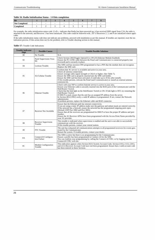
Communicator Troubleshooting 3G Alarm Communicator Installation Manual
26
For example, the radio initialization status code 12-45--- indicates that Radio has been powered up, it has received SMS signal from C24, the radio is attached to the network, and Receiver 1 has been initialized. This code could be followed with...567 if Receivers 2, 3, and 4 are initialized where appli-cable.If the radio initialization status code does not indicate any problems, proceed with installation as per this manual. If troubles are reported, reset the ini-tialization process. If this action does not fix the problem, refer to Trouble shooting section in this manual.
Table 17: Trouble Code Indications
Table 16: Radio Initialization Status - 1-8 bits completion
Bit 1 2 3 4 5 6 7 8
Not Completed - - - - - - - -
Completed 1 2 3 4 5 6 7 8
Trouble Indicator Digit Possible Causes Trouble Possible Solutions
00 No Trouble N/A
02 Panel Supervision Trou-ble
Check Section [382]Toggle Option[5] is ON (3G/Ethernet Module Enabled).Ensure the PC-LINK cable between the Panel and Communicator is connected properly (not reversed) and is securely in place.
04 Lockout Trouble The SIM card has incorrect PIN programmed or has a PIN that the module does not recognize. Replace the SIM card.
05 3G/Cellular Trouble
Confirm that 3G service is available and active in your area.Check all antenna connections.Ensure average radio signal strength is CSQ 6 or higher. (See Table 7).Ensure the SIM card is properly inserted into the SIM card holder.Ensure the SIM card has been activated. (Could take up to 24 hrs after install).If this trouble persists, relocate the Panel (and Communicator) or install an external antenna extension kit.
06 Ethernet Trouble
Check with your ISP to confirm Internet service is active in your area.Ensure your Ethernet cable is securely inserted into the RJ45 jack of the Communicator and the Hub/Router/ Switch.Check that the link light on the Hub/Router/ Switch is ON. If link light is OFF, try restarting the Hub/Router/ Switch.If DHCP is used, ensure that the unit has an assigned IP address from the server.In Section [851] [992] verify a valid IP address is programmed. If not, contact the Network administrator.If problem persists, replace the Ethernet cable and RJ45 connector.
07 Receiver Not Available
Ensure that the Ethernet path has internet connectivity.If you are using a static IP address make sure the gateway and subnet mask are entered correctly.If the network has a firewall, ensure the network has the programmed outgoing ports open (Default UDP Port 3060 and Port 3065).Ensure that all the receivers are programmed for DHCP or have the proper IP address and port number.Ensure the 3G Receiver APNs have been programmed with the Access Point Name provided by your 3G provider.
08 Receiver Supervision Trouble
This trouble is indicated when supervision is enabled and the unit is not able to successfully communicate with the receiver.If this trouble persists, contact your central station.
09 FTC TroubleThe unit has exhausted all communications attempts to all programmed receivers for events gen-erated by the Communicator.Restart the system. If trouble persists, contact your dealer.
0A Connect24 Configura-tion Failure
The SIM is active but there is no programming for the Communicator.Ensure a profile has been programmed in Connect-24 for the SIM.You can confirm your programming by calling the Connect-24 VRU, or by logging into the Connect24 VRU web site.
0C Module Configuration Trouble
This indication appears when Section [021] System Account Code, Section [101], [111], [201], and [211] Receiver Account Code have not been programmed. Ensure that a valid account code has been entered in these Sections.

3G Alarm Communicator Installation Manual Communicator Troubleshooting
27
Communicator TroubleshootingThe status code for the radio signal strength, its typical troubles, possible causes and troubleshooting instructions is displayed in the table below.
Table 18: Radio Signal Strength
The table below displays the Network indicator codes and meaning of each code.
Table 19: Network indicator - Digit 3
Signal Strength CSQ Level Signal
Indicator 1Signal
Indicator 2Signal Level
[dBm]Signal Level
Status Action Required
No Signal 0 0 0 -108.8 badCheck all antenna connections.Confirm 3G service is active in area.Relocate Panel.
1 Bar 1 - 4 0 2 -108 ~ -103 weak Relocate Panel if signal strength shows less than 3 bars.2 Bars 5 - 6 0 1 -102 ~ -99 weak
3 Bars 7 - 10 2 1 -98 ~ -91 strong
Location is OK. 3G Signal Strength is greater than CSQ 7.
4 Bars 11 - 13 2 1 -90 ~ -85 strong
5 Bars 14 + 1 1 -84 and higher excellent
Network indicator Value MeansOFF No Network Trouble
ON
Ethernet Cable disconnectedEthernet DHCP failedRadio connection has been restRadio IP failed
Flashing
Incoming transmissionConnect 24 programmingOutgoing transmissionIncoming transmission

Communicator Troubleshooting 3G Alarm Communicator Installation Manual
28

3G Alarm Communicator Installation Manual System Options
29
SYSTEM OPTIONS
[001] Ethernet IP AddressDefault (000.000.000.000)|____|____|____||____|____|____||____|____|____|____|____|____|
[002] Ethernet IP Subnet MaskDefault (255.255.255.000)|____|____|____||____|____|____||____|____|____|____|____|____|
[003] Ethernet Gateway IP AddressDefault (000.000.000.000)|____|____|____||____|____|____||____|____|____|____|____|____|
[004] Receiver Supervision IntervalDefault (0087/135) Valid range: 0000 - FFFF.
|____|____|____|____|
[005] System Toggle Options
|____| [1] Ethernet Receiver 1 Supervised Default (OFF).
|____| [2] Cellular Receiver 1 Supervised Default (OFF).
|____| [3] Supervision Type Default (OFF).
|____| [4] Primary Communications Path.
Default [OFF] TL2553G; [ON]3G2055.
|____| [5] Redundant Communications Default (OFF).
|____| [6] Remote Firmware Upgrade Default (ON).
|____| [7] Alternate Test Transmission Default (OFF).
|____| [8] Cellular Low Signal Trouble Default (OFF).
[006] System Toggle Options 2
|____| [1] Ethernet Receiver 1 Enabled Default (ON).
|____| [2] Ethernet Receiver 2 Enabled Default (ON).
|____| [4] Cellular Receiver 1 Enabled Default (ON).
|____| [5] Cellular Receiver 2 Enabled Default (ON).
|____| [7] DLS Over Cellular Default (ON).
|____| [8] Interactive Over Cellular Default (ON).
[007] DNS Server IP 1 Programming not permitted on UL/ULC listed system.
Default (000.000.000.000)|____|____|____||____|____|____||____|____|____|____|____|____|
[008] DNS Server IP 2 Programming not permitted on UL/ULC listed system.
Default (000.000.000.000)|____|____|____||____|____|____||____|____|____|____|____|____|
PROGRAMMING OPTIONS
[010] System Toggle OptionDefault (CAFE) Valid range: 0000 - FFFF.|____|____|____|____|
[011] Installer CodeDefault (CAFE) Valid range: 0000 - FFFF.
|____|____|____|____|
[012] DLS Incoming PortDefault (0BF6/3062) Valid range: 0000 - FFFF.
|____|____|____|____|
[013] DLS Outgoing Port Default (0BFA/3066) Valid range: 0000 - FFFF.
|____|____|____|____|
[020] Time ZoneDefault (CAFE) Valid range: 0000 - FFFF.|____|____|____|____|[022] Communications FormatDefault (04) Program 03 (CID), 04 (SIA).
|____|____|
[023] Panel Absent TroubleDefault (FF); Program 00 disable or FF enable.
|____|____|
[024] Panel Absent Trouble RestoreDefault (FF) Program 00 disable or FF enable.
|____|____|
[025] Radio Activation RestoreDefault (FF) Program 00 disable or FF enable.
|____|____|
SYSTEM TEST OPTIONS [026 - 029][026] Ethernet 1 TransmissionDefault (FF) Program 00 disable or FF enable.
|____|____|
[027] Ethernet 2 TransmissionDefault (00) Program 00 disable or FF enable.
|____|____|
[028] Cellular 1 TransmissionDefault (FF) Program 00 disable or FF enable.
|____|____|
[029] Cellular 2 TransmissionDefault (00) Program 00 disable or FF enable.
|____|____|
[030] FTC RestoreDefault (FF) Program 00 disable or FF enable.
|____|____|
[031] Priority Tamper AlarmDefault (FF) Program 00 disable or FF enable.
|____|____|
[032] Priority Tamper RestoreDefault (FF) Program 00 disable or FF enable.
|____|____|
[033] Communicator Firmware Update BeginDefault (FF) Program 00 disable or FF enable.
|____|____|
[034] Communicator Firmware Update SuccessfulDefault (FF) Program 00 disable or FF enable.
|____|____|
[035] Panel Firmware Update BeginDefault (FF) Program 00 disable or FF enable.
|____|____|
ETHERNET/CELLULAR PROGRAMMING WORKSHEETS

Ethernet Receiver 1 Options 3G Alarm Communicator Installation Manual
30
[036] Panel Firmware Update SuccessfulDefault (FF) Program 00 disable or FF enable.
|____|____|
[037] Panel Firmware Update FailDefault (FF) Program 00 disable or FF enable.
|____|____|
ETHERNET RECEIVER 1 OPTIONS
[101] Ethernet Receiver 1 Account CodeDefault (0000000000) Valid range: 0000000001 - FFFFFFFFFE.
|____|____|____|____|____|____|____|____|____|____|
[102] Ethernet Receiver 1 DNISDefault (000000) Valid range: 000000 - FFFFFF.
|____|____|____|____|____|____|
[103] Ethernet Receiver 1 AddressDefault (127.000.000.001)|____|____|____||____|____|____||____|____|____|____|____|____|
[104] Ethernet Receiver 1 Remote PortDefault (0BF5/3061) Valid range: 0000 - FFFF.
|____|____|____|____|
[105] Ethernet Receiver 1 Local PortDefault (0BF4/3060)Valid range: 0000 - FFFF.
|____|____|____|____|
[106] Ethernet Receiver 1 Domain NameDefault ( ) 32 ASCII characters. Programming not permitted on UL/ULC listed system. ________________________________
ETHERNET RECEIVER 2 OPTIONS
[111] Ethernet Receiver 2 Account CodeDefault (0000000000) Valid range: 0000000001 - FFFFFFFFFE.
|____|____|____|____|____|____|____|____|____|____|
[112] Ethernet Receiver 2 DNISDefault (000000) Valid range: 000000 - 0FFFFF.
|____|____|____|____|____|____|
[113] Ethernet Receiver 2 AddressDefault (000.000.000.000)|____|____|____||____|____|____||____|____|____|____|____|____|
[114] Ethernet Receiver 2 Remote PortDefault (0BF5/3061) Valid range: 0000 - FFFF.
|____|____|____|____|
[115] Ethernet Receiver 2 Local PortDefault (0BF9/3065) Valid range: 0000 -FFFF.
|____|____|____|____|
[116] Ethernet Receiver 2 Domain NameDefault ( ) Programming not permitted on UL/ULC listed system.
____________________________________
ETHERNET OPTIONS
[124] Ethernet Test Transmission TimeDefault (9999) Valid: 00-23(HH); 00-59(MM)
|____|____|____|____|
[125] Ethernet Test Transmission CycleDefault (000000)Valid range: 000000 - 999999 minutes.
|____|____|____|____|____|____|
CELLULAR RECEIVER 1 OPTIONS
[201] Cellular Receiver 1 Account CodeDefault (0000000000) Valid range: 0000000001 - FFFFFFFFFE.
|____|____|____|____|____|____|____|____|____|____|
[202] Cellular Receiver 1 DNISDefault (000000) Valid range: 000000 - 0FFFFF.
|____|____|____|____|____|____|
[203] Cellular Receiver 1 AddressDefault (000.000.000.000). Valid range: 000-255.|____|____|____||____|____|____||____|____|____|____|____|____|
[204] Cellular Receiver 1 PortDefault (0BF5/3061) Valid range: 0000 - FFFF.
|____|____|____|____|
[205] Cellular Receiver 1 APN Default ( )32 ASCII characters.
____________________________________

3G Alarm Communicator Installation Manual Cellular Receiver 2 Options
31
[206] Cellular Receiver 1 Domain NameDefault ( ) Programming not permitted on UL/ULC listed system.
32 Character ASCII characters.____________________________________
CELLULAR RECEIVER 2 OPTIONS
[211] Cellular Receiver 2 Account CodeDefault (0000000000)Valid range: 0000000001 - FFFFFFFFFE.
|____|____|____|____|____|____|____|____|____|____|
[212] Cellular Receiver 2 DNISDefault (000000)Valid range: 000000 - 0FFFFF.
|____|____|____|____|____|____|
[213] Cellular Receiver 2 AddressDefault (000.000.000.000)Valid segment range: 000-255|____|____|____||____|____|____||____|____|____|____|____|____|
[214] Cellular Receiver 2 PortDefault (0BF5/3061) Valid range: 0000 - FFFF.
|____|____|____|____|
[215] Cellular Receiver 2 APN Default ( ) 32 ASCII characters.
____________________________________
[216] Cellular Receiver 2 Domain NameDefault ( )
Programming not permitted on UL/ULC listed system.
32 ASCII characters.____________________________________
CELLULAR OPTIONS
[221] Cellular Public Access Point NameDefault ( ) 32 ASCII characters
____________________________________
[222] Cellular Login User NameDefault ( ) 32 ASCII characters.
____________________________________
[223] Cellular Login PasswordDefault ( ) 32 ASCII characters.
____________________________________
[224] Cellular Test Transmission Time of Day
Default (9999) Valid range: 00 - 23 hrs. (HH) 00 - 59 min. (MM).|____|____|____|____[225] Cellular Test Transmission CycleDefault (000000) Valid range: 000000 - 999999 minutes.
|____|____|____|____|____|____|
[226] Cellular Trouble DelayDefault (00)
Program 00 disable or FF enable.
|____|____|
[301] Command and Control Toggle Options
|____| [1] Reserved Default ( )
|____| [2] Reserved Default ( )
|____| [3] SMS Command and Control Default (ON).
|____| [4] Reserved Default ( )
|____| [5] SMS Character Format
|____| [6] Long SMS Message Handling Default (OFF)
|____| [7] Reserved Default ( )
|____| [8] Reserved Default ( )
[311] - [318] SMS Phone Number 1 - 8This section may be programmed through DLS IV or the keypad.
____________________________________
[321] - [328] SMS Phone Number 1 - 8 Toggle Options
|____| [1] SMS Notification Alarm/Restore Default (OFF)
|____| [2] SMS Notification Tamper/Restore Default (OFF)
|____| [3] SMS Notification Opening/Closing Default (OFF)
|____| [4] SMS Notification System Maintenance Default (OFF)
|____| [5] SMS Notification System Test Default (OFF)
|____| [6] SMS Notification Internal Events Default (OFF)
|____| [7] SMS Notification Enabled Default (OFF)
|____| [8] SMS Command and Control Enabled Default (ON)
[601] Stay ArmDefault (Stay Arm);Send this command to the system to stay arm.____________________________________
[602] Away ArmDefault (Away Arm);Send this command to the system to away arm.____________________________________[603] Night ArmDefault (Night Arm);Send this command to the system to night arm.____________________________________[604] DisarmDefault (Disarm);Send this command to the system to night disarm.____________________________________
[605] - [608] Activate Command Output 1 - 4Default (Activate Command Output n);Send this command to the system to activate a command output.____________________________________
[609] - [612] Deactivate Command Output 1 - 4Default (Deactivate Command Output n);Send this command to the system to deactivate a command output.____________________________________
[613] BypassDefault (Bypass);Send this command to the system to bypass a Zone.____________________________________
[614] UnbypassDefault (Unbypass);Send this command to the system to unbypass a Zone.____________________________________
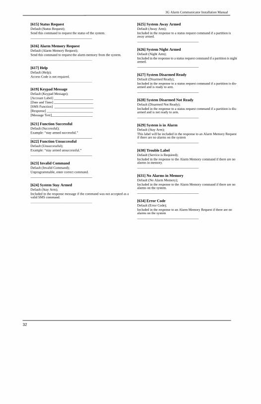
3G Alarm Communicator Installation Manual
32
[615] Status RequestDefault (Status Request);Send this command to request the status of the system.____________________________________
[616] Alarm Memory RequestDefault (Alarm Memory Request);Send this command to request the alarm memory from the system.____________________________________
[617] HelpDefault (Help);Access Code is not required.____________________________________
[619] Keypad MessageDefault (Keypad Message);[Account Label] _______________________[Date and Time] _______________________[SMS Function] _______________________[Response] ___________________________[Message Text]________________________
[621] Function SuccessfulDefault (Successful);Example: “stay armed successful.”____________________________________[622] Function UnsuccessfulDefault (Unsuccessful);Example: “stay armed unsuccessful.”____________________________________
[623] Invalid CommandDefault (Invalid Command);Unprogrammable, enter correct command.____________________________________
[624] System Stay ArmedDefault (Stay Arm);Included in the response message if the command was not accepted as a valid SMS command.____________________________________
[625] System Away ArmedDefault (Away Arm);Included in the response to a status request command if a partition is away armed.____________________________________
[626] System Night ArmedDefault (Night Arm);Included in the response to a status request command if a partition is night armed.____________________________________
[627] System Disarmed ReadyDefault (Disarmed Ready);Included in the response to a status request command if a partition is dis-armed and is ready to arm.____________________________________
[628] System Disarmed Not ReadyDefault (Disarmed Not Ready);Included in the response to a status request command if a partition is dis-armed and is not ready to arm.____________________________________
[629] System is in AlarmDefault (Stay Arm);This label will be included in the response to an Alarm Memory Request if there are no alarms on the system____________________________________
[630] Trouble LabelDefault (Service is Required);Included in the response to the Alarm Memory command if there are no alarms in memory.____________________________________
[631] No Alarms in MemoryDefault (No Alarm Memory);Included in the response to the Alarm Memory command if there are no alarms on the system.____________________________________
[634] Error CodeDefault (Error Code);Included in the response to an Alarm Memory Request if there are no alarms on the system____________________________________

3G Alarm Communicator Installation Manual System Information (Read Only)
33
[901] Diagnostic Test Transmission
|___| [1] Ethernet 1 Default (OFF).
|___| [2] Ethernet 2 Default (OFF).
|___| [3] Cellular 1 Default (OFF).
|___| [4] Cellular 2 Default (OFF).
SYSTEM INFORMATION (READ ONLY)[988] DNS 1 IP Address|____|____|____||____|____|____||____|____|____|____|____|____|
[989] DNS 2 IP Address|____|____|____||____|____|____||____|____|____|____|____|____|
[991] Firmware Version
|____|____|____|____|____|____|____|____|
[992] Ethernet IP Address|____|____|____||____|____|____||____|____|____|____|____|____|
[993] Ethernet Gateway Address|____|____|____||____|____|____||____|____|____|____|____|____|
[994] Cellular IP Address|____|____|____||____|____|____||____|____|____|____|____|____|
[995] SIM Number ____________________________________
[996] Cellular Telephone NumberThis number is required for DLS, and Firmware upgrades.
____________________________________
[997] IMEI Number____________________________________
[998] MAC Address
|____|____|____|____|____|____| |____|____|____|____|____|____|
SYSTEM RESET DEFAULTS
[999] Software DefaultDefault (99); Valid entries are 00 or 55
|____|____|

End User Licence Agreement 3G Alarm Communicator Installation Manual
34
END USER LICENCE AGREEMENT
IMPORTANT - READ CAREFULLY: DSC Software purchased with or without Products and Components is Copyrighted and is pur-chased under the following license terms:
This End-User License Agreement (EULA) is a legal agreement between You (thecompany, individual or entity who acquired the SOFTWARE and any relatedHARDWARE) and Digital Security Controls (DSC), a division of Tyco SafetyProducts Canada Ltd., the manufacturer of the integrated security systems and thedeveloper of the software and any related products or components (‘HARD-WARE’) which you acquired. If the DSC software product (‘SOFTWARE PRODUCT’ or ‘SOFTWARE’) isintended to be accompanied by HARDWARE, and is NOT accompanied by newHARDWARE, You may not use, copy or install the SOFTWARE PRODUCT. TheSOFTWARE PRODUCT includes computer software, and may include associatedmedia, printed materials, and ‘online’ or electronic documentation. Any software provided along with the SOFTWARE PRODUCT that is associatedwith a separate EULA is licensed to You under the terms of that license agreement. By installing, copying, downloading, storing, accessing, or otherwise using theSOFTWARE PRODUCT, You agree unconditionally to be bound by the terms ofthis EULA, even if this EULA is deemed to be a modification of any previousarrangement or contract. If You do not agree to the terms of this EULA, DSC isunwilling to license the SOFTWARE PRODUCT to You, and You have no right touse it.SOFTWARE PRODUCT LICENSEThe SOFTWARE PRODUCT is protected by copyright laws and internationalcopyright treaties, as well as other intellectual property laws and treaties. TheSOFTWARE PRODUCT is licensed, not sold, under the following terms:.GRANT OF LICENSE This EULA grants You the following rights:Software Installation and Use - For each license You acquire, You may have onlyone copy of the SOFTWARE PRODUCT installed. Storage/Network Use - The SOFTWARE PRODUCT may not be installed,accessed, displayed, run, shared or used concurrently on or from different comput-ers, including a workstation, terminal or other digital electronic device (‘Device’).In other words, if You have several workstations, You will have to acquire a licensefor each workstation where the SOFTWARE will be used.Backup Copy - You may make back-up copies of the SOFTWARE PRODUCT,but You may only have one copy per license installed at any given time. You mayuse the back-up copy solely for archival purposes. Except as expressly provided inthis EULA, You may not otherwise make copies of the SOFTWARE PRODUCT,including the printed materials accompanying the SOFTWARE. DESCRIPTION OF OTHER RIGHTS AND LIMITATIONS Limitations on Reverse Engineering, Decompilation and Disassembly - Youmay not reverse engineer, decompile, or disassemble the SOFTWARE PRODUCT,except and only to the extent that such activity is expressly permitted by applicablelaw notwithstanding this limitation. You may not make any changes or modifica-tions to the Software, without the written permission of an officer of DSC. You maynot remove any proprietary notices, marks or labels from the Software Product.You shall institute reasonable measures to ensure compliance with the terms andconditions of this EULA.Separation of Components - The SOFTWARE PRODUCT is licensed as a singleproduct. Its component parts may not be separated for use on more than oneHARDWARE unit.Single INTEGRATED PRODUCT - If You acquired this SOFTWARE withHARDWARE, then the SOFTWARE PRODUCT is licensed with the HARD-WARE as a single integrated product. In this case, the SOFTWARE PRODUCTmay only be used with the HARDWARE as set forth in this EULA.Rental - You may not rent, lease or lend the SOFTWARE PRODUCT. You maynot make it available to others or post it on a server or web site.Software Product Transfer - You may transfer all of Your rights under this EULAonly as part of a permanent sale or transfer of the HARDWARE, provided Youretain no copies, You transfer all of the SOFTWARE PRODUCT (including allcomponent parts, the media and printed materials, any upgrades and this EULA),and provided the recipient agrees to the terms of this EULA. If the SOFTWAREPRODUCT is an upgrade, any transfer must also include all prior versions of theSOFTWARE PRODUCT.
Termination - Without prejudice to any other rights, DSC may terminate thisEULA if You fail to comply with the terms and conditions of this EULA. In suchevent, You must destroy all copies of the SOFTWARE PRODUCT and all of itscomponent parts.Trademarks - This EULA does not grant You any rights in connection with anytrademarks or service marks of DSC or its suppliers.COPYRIGHT - All title and intellectual property rights in and to the SOFTWAREPRODUCT (including but not limited to any images, photographs, and text incor-porated into the SOFTWARE PRODUCT), the accompanying printed materials,and any copies of the SOFTWARE PRODUCT, are owned by DSC or its suppliers.You may not copy the printed materials accompanying the SOFTWARE PROD-UCT. All title and intellectual property rights in and to the content which may beaccessed through use of the SOFTWARE PRODUCT are the property of therespective content owner and may be protected by applicable copyright or otherintellectual property laws and treaties. This EULA grants You no rights to use suchcontent. All rights not expressly granted under this EULA are reserved by DSC andits suppliers.EXPORT RESTRICTIONS - You agree that You will not export or reexport theSOFTWARE PRODUCT to any country, person, or entity subject to Canadianexport restrictions. CHOICE OF LAW - This Software License Agreement is governed by the lawsof the Province of Ontario, Canada. ARBITRATION - All disputes arising in connection with this Agreement shall bedetermined by final and binding arbitration in accordance with the Arbitration Act,and the parties agree to be bound by the arbitrator’s decision. The place of arbitra-tion shall be Toronto, Canada, and the language of the arbitration shall be English.7. LIMITED WARRANTYNO WARRANTY - DSC provides the SOFTWARE ‘as is’ without warranty. DSCdoes not warrant that the SOFTWARE will meet your requirements or that opera-tion of the SOFTWARE will be uninterrupted or error free.CHANGES IN OPERATING ENVIRONMENT - DSC shall not be responsiblefor problems caused by changes in the operating characteristics of the hardware, orfor problems in the interaction of the SOFTWARE with non DSC software or hard-ware products.LIMITATION OF LIABILITY; WARRANTY REFLECTS ALLOCATIONOF RISK -In any event, if any statute implies warranties or conditions not statedin this license agreement, entire liability under any provision of this license agree-ment shall be limited to the greater of the amount actually paid by you to license theSOFTWARE and five Canadian dollars (CAD$5.00). because some jurisdictionsdo not allow the exclusion or limitation of liability for consequential or incidentaldamages, the above limitation may not apply to you.DISCLAIMER OF WARRANTIES - This warranty contains the entire warrantyand shall be in lieu of any and all other warranties, whether expressed or implied(including all implied warranties of merchantability or fitness for a particular pur-pose) and of all other obligations or liabilities on the part of DSC. DSC makes noother warranties. DSC neither assumes nor authorizes any other person purportingto act on its behalf to modify or to change this warranty, nor to assume for it anyother warranty or liability concerning this SOFTWARE PRODUCT.EXCLUSIVE REMEDY AND LIMITATION OF WARRANTY - Under nocircumstances shall DSC be liable for any special, incidental, consequential or indi-rect damages based upon breach of warranty, breach of contract, negligence, strictliability, or any other legal theory. such damages include, but are not limited to, lossof profits, loss of the SOFTWARE or any associated equipment, cost of capital,cost of substitute or replacement equipment, facilities or services, down time, pur-chasers time, the claims of third parties, including customers, and injury to prop-erty. DSC recommends that the entire system be completely tested on a regular basis.However, despite frequent testing, and due to, but not limited to, criminal tamper-ing or electrical disruption, it is possible for this Software Product to fail to performas expected.

3G Alarm Communicator Installation Manual Limited Warranty
35
LIMITED WARRANTY
Digital Security Controls (DSC) warrants the original purchaserthat for a period of twelve (12) months from the date of purchase,the product shall be free of defects in materials and workmanshipunder normal use. During the warranty period, Digital SecurityControls shall, at its option, repair or replace any defective prod-uct upon return of the product to its factory, at no charge forlabour and materials. Any replacement and/or repaired parts arewarranted for the remainder of the original warranty or ninety(90) days, whichever is longer. The original purchaser mustpromptly notify Digital Security Controls in writing that there isdefect in material or workmanship, such written notice to bereceived in all events prior to expiration of the warranty period.There is absolutely no warranty on software and all softwareproducts are sold as a user license under the terms of the softwarelicense agreement included with the product. The Customerassumes all responsibility for the proper selection, installation,operation and maintenance of any products purchased from DSC.Custom products are only warranted to the extent that they do notfunction upon delivery. In such cases, DSC can replace or credit atits option.
International WarrantyThe warranty for international customers is the same as for anycustomer within Canada and the United States, with the exceptionthat Digital Security Controls shall not be responsible for any cus-toms fees, taxes, or VAT that may be due.
Warranty ProcedureTo obtain service under this warranty, please return the item(s) inquestion to the point of purchase. All authorized distributors anddealers have a warranty program. Anyone returning goods to Dig-ital Security Controls must first obtain an authorization number.Digital Security Controls will not accept any shipment whatso-ever for which prior authorization has not been obtained.Conditions to Void WarrantyThis warranty applies only to defects in parts and workmanshiprelating to normal use. It does not cover:
• damage incurred in shipping or handling;• damage caused by disaster such as fire, flood, wind, earthquake
or lightning;• damage due to causes beyond the control of Digital Security
Controls such as excessive voltage, mechanical shock or waterdamage;
• damage caused by unauthorized attachment, alterations, modi-fications, or foreign objects;
• damage caused by peripherals (unless such peripherals weresupplied by Digital Security Controls);
• defects caused by failure to provide a suitable installation envi-ronment for the products;
• damage caused by use of the products for purposes other thanthose for which it was designed;
• damage from improper maintenance; or• damage arising out of any other abuse, mishandling or
improper application of the products.
Items Not Covered by WarrantyIn addition to the items which void the Warranty, the followingitems shall not be covered by Warranty:freight cost to the repair centre;products which are not identified with DSC's product label and lotnumber or serial number; or
products disassembled or repaired in such a manner as toadversely affect performance or prevent adequate inspection ortesting to verify any warranty claim.Access cards or tags returned for replacement under warranty willbe credited or replaced at DSC's option. Products not covered bythis warranty, or otherwise out of warranty due to age, misuse, ordamage shall be evaluated, and a repair estimate shall be pro-vided. No repair work will be performed until a valid purchaseorder is received from the Customer and a Return MerchandiseAuthorisation number (RMA) is issued by DSC's Customer Ser-vice.Digital Security Controls’ liability for failure to repair the productunder this warranty after a reasonable number of attempts will belimited to a replacement of the product, as the exclusive remedyfor breach of warranty. Under no circumstances shall DigitalSecurity Controls be liable for any special, incidental, or conse-quential damages based upon breach of warranty, breach of con-tract, negligence, strict liability, or any other legal theory. Suchdamages include, but are not limited to, loss of profits, loss of theproduct or any associated equipment, cost of capital, cost of sub-stitute or replacement equipment, facilities or services, downtime, purchaser’s time, the claims of third parties, including cus-tomers, and injury to property. The laws of some jurisdictionslimit or do not allow the disclaimer of consequential damages. Ifthe laws of such a jurisdiction apply to any claim by or againstDSC, the limitations and disclaimers contained here shall be to thegreatest extent permitted by law. Some states do not allow theexclusion or limitation of incidental or consequential damages, sothat the above may not apply to you.Disclaimer of WarrantiesThis warranty contains the entire warranty and shall be in lieu ofany and all other warranties, whether expressed or implied(including all implied warranties of merchantability or fitness fora particular purpose) and of all other obligations or liabilities onthe part of Digital Security Controls Digital Security Controls nei-ther assumes responsibility for nor authorizes any other personpurporting to act on its behalf to modify or to change this war-ranty, nor to assume for it any other warranty or liability concern-ing this product.This disclaimer of warranties and limited warranty are governedby the laws of the province of Ontario, Canada. Digital Security Controls recommends that the entire system becompletely tested on a regular basis. However, despite frequenttesting, and due to, but not limited to, criminal tampering or elec-trical disruption, it is possible for this product to fail to perform asexpected.Out of Warranty RepairsDigital Security Controls will at its option repair or replace out-of-warranty products which are returned to its factory accordingto the following conditions. Anyone returning goods to DigitalSecurity Controls must first obtain an authorization number. Digi-tal Security Controls will not accept any shipment whatsoever forwhich prior authorization has not been obtained.Products which Digital Security Controls determines to be repair-able will be repaired and returned. A set fee which Digital Secu-rity Controls has predetermined and which may be revised fromtime to time, will be charged for each unit repaired.

FCC Compliance Statement
CAUTION: Changes or modifications not expressly approved by the Digital Security Controls could voidyour authority to use this equipment.
This equipment has been tested and found to comply with the limits for a Class B digital device, pursuant to Part 15 of the FCC Rules.These limits are designed to provide reasonable protection against harmful interference in a residential installation. This equipmentgenerates, uses and can radiate radio frequency energy and, if not installed and used in accordance with the instructions, may causeharmful interference to radio communications. However, there is no guarantee that interference will not occur in a particular installa-tion. If this equipment does cause harmful interference to radio or television reception, which can be determined by turning the equip-ment off and on, the user is encouraged to try to correct the interference by one or more of the following measures:- Re-orient the receiving antenna.- Increase the separation between the equipment and receiver.- Connect the equipment into an outlet on a circuit different from that to which the receiver is connected.- Consult the dealer or an experienced radio/television technician for help.The user may find the following booklet prepared by the FCC useful: ‘How to Identify and Resolve Radio/Television InterferenceProblems’. This booklet is available from the U.S. Government Printing Office, Washington D.C. 20402, Stock # 004-000-00345-4.
WARNING: TO SATISFY FCC RF EXPOSURE REQUIREMENTS FOR MOBILE TRANSMITTING DEVICES, A SEPARATION DIS-TANCE OF 20CM OR MORE MUST BE MAINTAINED BETWEEN THE ANTENNA OF THIS DEVICE AND PERSONS DURING DEVICE OPERATION.
Industry Canada StatementThe prefix ‘IC:’ in front of the radio certification number signifies only that Industry Canada technical specifications were met.Certification Number IC: 160A-3G255SMThis device complies with Industry Canada licence-exempt RSS standard(s). Operation is subject to the following tow conditions: (1)this device may not cause interference, and (2) this device must accept any interference, including interference that may cause unde-sired operation of the device.Cet appareil est conforme avec Industrie Canada exempts de licence standard RSS (s). Le fonctionnement est soumis aux deux condi-tions suivantes: (1) cet appareil ne peut pas provoquer d'interférences et (2) cet appareil doit accepter toute interférence, y compris lesinterferences qui peuvent causer un mauvais fonctionnement de l'appareil.This Class B digital apparatus complies with Canadian ICES-003.Cet appareil numérique de la classe B est conforme à la norme NMB-003 du Canada.
© 2012 Tyco International Ltd. and its Respective Companies. All Rights Reserved.Toronto, Canada · www.dsc.comTech Support: 1-800-387-3630 (CA, US), 905-760-3000Printed in Canada
2 9 0 0 7 8 5 0 R0 0 4