
2900_3900_manual_parte_3
28
5-25 Cisco 2900 and 3900 Series Hardware Installation OL-18712-01 Chapter 5 Installing and Upgrading Internal Modules and FRUs Replacing Power Supplies and Redundant Power Supplies Figure 5-24 Lifting the 2901 Power Supply In or Out Step 6 Insert the replacement power supply into the chassis. See Figure 5-24. Step 7 Insert the screws that fasten the power supply to the chassis. See Figure 5-23. Step 8 Connect the power supply cable to the power supply connector. Step 9 Replace the chassis cover and connect power to the router. Replacing the Cisco 2911 Router Power Supply Warning Blank faceplates and cover panels serve three important functions: they prevent exposure to hazardous voltages and currents inside the chassis; they contain electromagnetic interference (EMI) that might disrupt other equipment; and they direct the flow of cooling air through the chassis. Do not operate the system unless all cards, faceplates, front covers, and rear covers are in place. Statement 1029 Several power supply options are available for the Cisco 2911 router. See Table 5-2 on page 5-23. All the power supply options have the same modular form factor for easy removal and replacement. Step 1 Completely loosen the two captive screws on the power supply module. See Figure 5-25. 250970 DO NOT REMOVE DURING NETWORK OPERATION DO NOT REMOVE DURING NETWORK OPERATION
-
Upload
consultach -
Category
Documents
-
view
23 -
download
0
Transcript of 2900_3900_manual_parte_3

5-25Cisco 2900 and 3900 Series Hardware Installation
OL-18712-01
Chapter 5 Installing and Upgrading Internal Modules and FRUs Replacing Power Supplies and Redundant Power Supplies
Figure 5-24 Lifting the 2901 Power Supply In or Out
Step 6 Insert the replacement power supply into the chassis. See Figure 5-24.
Step 7 Insert the screws that fasten the power supply to the chassis. See Figure 5-23.
Step 8 Connect the power supply cable to the power supply connector.
Step 9 Replace the chassis cover and connect power to the router.
Replacing the Cisco 2911 Router Power Supply
Warning Blank faceplates and cover panels serve three important functions: they prevent exposure to hazardous voltages and currents inside the chassis; they contain electromagnetic interference (EMI) that might disrupt other equipment; and they direct the flow of cooling air through the chassis. Do not operate the system unless all cards, faceplates, front covers, and rear covers are in place. Statement 1029
Several power supply options are available for the Cisco 2911 router. See Table 5-2 on page 5-23. All the power supply options have the same modular form factor for easy removal and replacement.
Step 1 Completely loosen the two captive screws on the power supply module. See Figure 5-25.25
0970
DO NOT REMOVE DURING NETWORK OPERATION
DO NOT REMOVE DURING NETWORK OPERATION

5-26Cisco 2900 and 3900 Series Hardware Installation
OL-18712-01
Chapter 5 Installing and Upgrading Internal Modules and FRUs Replacing Power Supplies and Redundant Power Supplies
Figure 5-25 Cisco 2911 Power Supply Components.
Step 2 Pull the power supply module straight out of the chassis.
Step 3 Insert the replacement power supply module and tighten the captive screws.
Replacing the Cisco 2911 Router Redundant Power SupplyThe redundant power supply (RPS) for the Cisco 2911 router is an external RPS. The external RPS attaches to a connector on the front of the router. In order for an RPS to be attached, the Cisco 2911 must be fitted with an RPS adapter. See Figure 5-26. See “Installing and Removing a Redundant Power Supply Adapter” section on page 5-29.
Figure 5-26 Cisco 2911 Redundant Power Supply Adapter.
1 Power supply 2 Power supply fastening screws (2)
DO NOT REMOVE DURINGNETWORK OPERATION
DO NOT REMOVE DURINGNETWORK OPERATION
2509
77
1 2 2
1 RPS Adapter 2 RPS fastening screws (2)
2509
80
1
2
2

5-27Cisco 2900 and 3900 Series Hardware Installation
OL-18712-01
Chapter 5 Installing and Upgrading Internal Modules and FRUs Replacing Power Supplies and Redundant Power Supplies
Replacing the Cisco 2921, Cisco 2951, or Cisco 3900 Series Power Supply
Warning Blank faceplates and cover panels serve three important functions: they prevent exposure to hazardous voltages and currents inside the chassis; they contain electromagnetic interference (EMI) that might disrupt other equipment; and they direct the flow of cooling air through the chassis. Do not operate the system unless all cards, faceplates, front covers, and rear covers are in place. Statement 1029
Several power supply options are available for the Cisco 2921, 2951 and 3900 series routers. See “Power Supply Compatibility”. All the power supply and RPS options have a similar modular form factor, with no cabling, for easy removal and replacement. If an RPS is attached, the power supply may be hot-swapped.
Note Read through this entire procedure and have all your tools and replacement power supply ready before performing a hot-swap. The hot-swap procedure requires removal of the cooling fans. You have only a few minutes to replace the fans before the router powers off, because the router will reach the upper temperature limits.
Step 1 For the Cisco 2921 and 2951, skip to Step 2. For the Cisco 3900 series routers pull straight out on the bezel to remove it along with the optional air filter from the fan tray assembly. See Figure 5-27 on page 5-28.

5-28Cisco 2900 and 3900 Series Hardware Installation
OL-18712-01
Chapter 5 Installing and Upgrading Internal Modules and FRUs Replacing Power Supplies and Redundant Power Supplies
Figure 5-27 Cisco 2921, 2951, and 3900 Series Power Supply Components.
Step 2 Completely loosen the four captive screws on each corner of the fan tray assembly and pull out the fan tray assembly. See Figure 5-27.
Step 3 Completely loosen the two captive screws on the power supply module. See Figure 5-27.
Step 4 Pull on the two captive power supply fastening screws to leverage the power supply from its connector, and then pull the power supply module straight out of the chassis.
Step 5 Insert the replacement power supply module, and tighten the captive screws.
Step 6 Reinstall the fan tray and bezel assemblies.
1 Fan tray or bezel assembly 2 Power supply
3 Power supply fastening screws (2) 4 RPS adapter (optional, Cisco 2911, 2921, or 2951 routers only) or secondary power supply (Cisco 3900 series routers)
5 RPS or secondary power supply fastening screws (2)
6
2509
08
1
4
2
5
5
3
SYS ACT SYS PWR1
AUX PWR1
SYS PWR2
AUX PWR2
Cisco 2900 Series

5-29Cisco 2900 and 3900 Series Hardware Installation
OL-18712-01
Chapter 5 Installing and Upgrading Internal Modules and FRUs Replacing Power Supplies and Redundant Power Supplies
Installing and Removing a Redundant Power Supply AdapterThe redundant power supply (RPS) for the Cisco 2911, 2921, or 2951 router is an external Cisco RPS 2300. To connect the RPS, the router must be fitted with an RPS adapter. A blank panel must be removed before installing the RPS adapter. The external RPS attaches to a connector on the front of the adapter.
Tip For information specific to the RPS 2300 see the Cisco Redundant Power Supply System Hardware Installation Guide at the following URL: http://www.cisco.com/en/US/docs/switches/power_supplies/rps2300/hardware/installation/guide/2300hig.html
Depending upon RPS configuration, more than one router can be backed up.
Caution Failure to follow the RPS Installation or Removal procedures can cause damage to the router, RPS adapter, RPS cable, or RPS.
Figure 5-28 Cisco 2911 Redundant Power Supply Adapter.
1 RPS Adapter 2 RPS fastening screws (2)25
0980
1
2
2
Table 5-3 RPS 2300 Backup Capabilities
Power Mode
Quantity and Type of RPS 2300 FRU
Quantity 1 C3K-PWR-750WAC
Quantity 2 C3K-PWR-750WAC
Quantity 1 C3K-PWR-1150WAC
Quantity 2C3K-PWR-1150WAC
2911 in RPS 1 2 1 2
2921, 2951 in RPS
0 1 0 1
2911 in POE Boost
0 1 1 2
2921, 2951 in POE Boost
0 1 0 1

5-30Cisco 2900 and 3900 Series Hardware Installation
OL-18712-01
Chapter 5 Installing and Upgrading Internal Modules and FRUs Replacing Power Supplies and Redundant Power Supplies
Installing an RPS Adapter
To install an RPS adapter, perform the following procedure.
Warning The RPS adapter must be in the router chassis before connecting to the RPS.
Step 1 Ensure AC or DC power is disconnected from the router power supply.
Step 2 If connected, place the RPS 2300 into standby mode. Consult the Cisco Redundant Power System 2300 Hardware Installation Guide for operating the RPS 2300.
Step 3 If an RPS Adapter had never been installed, a blank panel is in it’s place. Remove the RPS Adapter blank panel.
Step 4 Insert the RPS adapter into the router (Figure 5-26 or Figure 5-27) and tighten the screws.
Step 5 Connect the RPS 2300 cable into the RPS adapter connector.
Step 6 Connect the other end of the RPS 2300 cable to the RPS 2300.
Step 7 Power up the router.
Step 8 Place the RPS into Active mode.
Removing an RPS Adapter
To remove an RPS adapter, perform the following procedure.
Step 1 If connected, place the RPS 2300 into standby mode. Consult the Cisco Redundant Power System 2300 Hardware Installation Guide for operating the RPS 2300.
Step 2 Power off and disconnect the AC or DC power from the router power supply.
Step 3 Remove the RPS cable from the RPS 2300.
Step 4 Remove the other end of the RPS 2300 cable from the RPS adapter.
Step 5 Remove the RPS adapter.
Cisco 2911, 2921, and 2951 Power and RPS Error Messages
There are many RPS error messages unique to the Cisco 2911, 2921, and 2951 routers. The messages display on the router console terminal. Table 5-2 lists the messages and their meanings.

5-31Cisco 2900 and 3900 Series Hardware Installation
OL-18712-01
Chapter 5 Installing and Upgrading Internal Modules and FRUs Replacing a Fan Tray or Air Filter
Replacing a Fan Tray or Air FilterThe Cisco 2900 and 3900 series routers have hot-swappable fan trays and air filters that are field replaceable units (FRUs). The fan tray includes all of the router fans in one assembly. If a fan fails, replace the tray using a flat-blade or Phillips-head screwdriver.
Caution It is recommended to replace fan filters every six months, or when dirty, whichever comes first.
Table 5-4 Cisco 2911, 2921, and 2951 Power and RPS Error Messages
Message Condition
An unsupported RPS is connected or cable is not inserted properly
During reload, IOS can not read the RPS2300 PID, or the RPS2300 PID does not match. Note that RPS2300 PID is read over the I2C link between the Router and the RPS2300. The error could also indicate there is a cable connectivity problem.
Power supplies inserted in RPS are incompatible The RPS 2300 FRUs are different. FRUs can be either 1150W or 750W. The RPS does not support differing FRUs. See Table 5-2.
RPS has a critical fault During reload, the RPS2300 has an over-current, over-temperature, or under-voltage condition.
RPS is not ready for configuration The RPS2300 is busy handling control or configuration commands from the connected load units (LUs), and the router is trying to send command to the RPS2300.
RPS is not available for backup The RPS2300 is backing up other LUs and it can not backup the current router.
One critical RPS fault has occurred or RPS power supply is not good
During runtime, the RPS2300 encountered an over-current, over-temperature, or under-voltage condition, or the power supplies is faulty.
RPS is disconnected or powered off RPS2300 is disconnected or powered off.
An unsupported RPS is connected. During reload or runtime, an unsupported RPS2300 is connected to the router.
RPS OIR insertion is not supported. Reload the router for power redundancy.
During runtime, the supported RPS2300 is connected to the router.
Chassis power is not good in PSU 1 During runtime, the power input source was removed from the internal power supply.
Input source is removed from PSU 1 During runtime, the power input source was removed from the internal power supply.
PSU's PoE power is not good in slot 1 During runtime, the PoE power from the internal power supply failed.
PSU is removed in slot 1 The internal power supply is removed.

5-32Cisco 2900 and 3900 Series Hardware Installation
OL-18712-01
Chapter 5 Installing and Upgrading Internal Modules and FRUs Replacing a Fan Tray or Air Filter
Before Hot-Swapping a Fan Tray
• Read the entire procedure and have the required tools on hand.
• Do not attempt the hot-swap in ambient air temperature above 90°F (32 C).
• Do not attempt the hot-swap at an altitude above 6000 feet (1829 meters).
• When the router is being operated, it is recommended to change the fans within the following times to ensure the router does not overheat:
– Cisco 2911 within 2 minutes
– Cisco 2921 or 2951 within 2 minutes
– Cisco 3900 series within 1.5 minutes
The Cisco 2900 and 3900 Integrated Services Routers (ISRs) fan tray and air filter replacement instructions are provided next:
Cisco 2911
• Replacing the Cisco 2911 Fan Tray, page 5-32
• Replacing the Cisco 2911 Air Filter, page 5-33
Cisco 2921 and Cisco 2951
• Replacing the Cisco 2921 or 2951 Fan Tray, page 5-34
Cisco 2900 and Cisco 3900 Series
• Replacing the Cisco 3900 Series Fan Tray, page 5-34
• Replacing the Cisco 3900 Series Air Filter, page 5-35
Replacing the Cisco 2911 Fan TrayIf hot-swapping the fan tray, it is recommended to complete the operation within 2-minutes to ensure the router remains within operating temperature.
Step 1 Unsnap the bezel by pulling it straight out from the chassis. See Figure 5-29.
5-33Cisco 2900 and 3900 Series Hardware Installation
OL-18712-01
Chapter 5 Installing and Upgrading Internal Modules and FRUs Replacing a Fan Tray or Air Filter
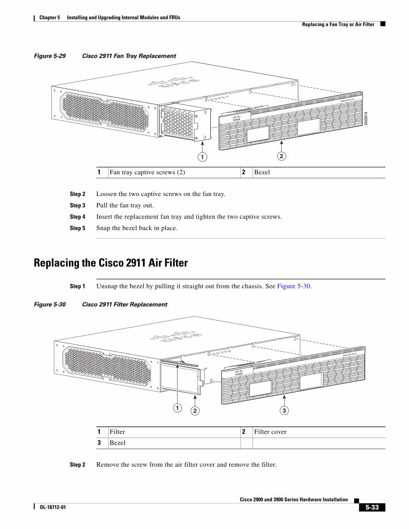
Figure 5-29 Cisco 2911 Fan Tray Replacement
Step 2 Loosen the two captive screws on the fan tray.
Step 3 Pull the fan tray out.
Step 4 Insert the replacement fan tray and tighten the two captive screws.
Step 5 Snap the bezel back in place.
Replacing the Cisco 2911 Air Filter
Step 1 Unsnap the bezel by pulling it straight out from the chassis. See Figure 5-30.
Figure 5-30 Cisco 2911 Filter Replacement
Step 2 Remove the screw from the air filter cover and remove the filter.
1 Fan tray captive screws (2) 2 Bezel
1 Filter 2 Filter cover
3 Bezel
2509
74
Cisco 2900 Series
1 2
Cisco 2900 Series
1 3 2

5-34Cisco 2900 and 3900 Series Hardware Installation
OL-18712-01
Chapter 5 Installing and Upgrading Internal Modules and FRUs Replacing a Fan Tray or Air Filter
Step 3 Install the replacement air filter, air filter cover, and the bezel.
Replacing the Cisco 2921 or 2951 Fan TrayIf hot-swapping the fan tray, it is recommended to complete the operation within 2-minutes to ensure the router remains within operating temperature.
Step 1 Pry open the fan tray screw covers on the four captive fan tray screws.
Step 2 Completely loosen the four captive fan tray screws.
Step 3 Pull the fan tray out.
Step 4 Insert the replacement fan tray and tighten the four captive screws.
Step 5 Snap the screw covers back in place.
Figure 5-31 Cisco 2921 and 2951 Fan Tray Replacement
Replacing the Cisco 3900 Series Fan TrayIf hot-swapping the fan tray, it is recommended to complete the operation within 1.5-minutes to ensure the router remains within operating temperature.
Step 1 Unsnap the bezel by pulling it straight out from the chassis. Initially, the bezel fits very tightly. See Figure 5-32.
1 Fan tray and bezel assembly 2 Fan tray screw covers X4
3 Fan tray screws X425
0907
1
SYS ACT SYSPWR1
AUXPWR1
SYSPWR2
AUXPWR2
Cisco 2900 Series

5-35Cisco 2900 and 3900 Series Hardware Installation
OL-18712-01
Chapter 5 Installing and Upgrading Internal Modules and FRUs Replacing a Fan Tray or Air Filter
Figure 5-32 Removing the Cisco 3900 Series Router Bezel)
Step 2 Completely loosen the four captive screws on the fan tray.
Step 3 Pull out the fan tray.
Step 4 Insert the replacement fan tray, and tighten the four captive screws as shown in Figure 5-33.
Figure 5-33 Cisco 3900 Series Fan Tray Replacement
Step 5 Snap the bezel back in place.
Replacing the Cisco 3900 Series Air Filter
Step 1 Unsnap the bezel by pulling it straight out from the chassis. See Figure 5-34.
1 Bezel
2509
20
SYS ACT SYSPWR1
AUXPWR1
SYSPWR2
AUXPWR2
Cisco 3900 Series
1
2509
21

5-36Cisco 2900 and 3900 Series Hardware Installation
OL-18712-01
Chapter 5 Installing and Upgrading Internal Modules and FRUs Replacing a Fan Tray or Air Filter
Figure 5-34 Removing the Cisco 3900 Series Router Bezel)
Step 2 The filter is recessed inside the bezel. Insert the replacement filter inside the bezel, and snap the bezel back in place. See Figure 5-35.
Figure 5-35 Replacing the Cisco 3900 Series Air Filters)
1 Bezel
2509
20
SYS ACT SYSPWR1
AUXPWR1
SYSPWR2
AUXPWR2
Cisco 3900 Series
1
1 Bezel 2 Snaps (stationary)
3 Air filter
SYS ACT SYS PWR1
AUX PWR1
SYS PWR2
AUX PWR2
Cisco 3900 Series
2509
19
1 3 2

5-37Cisco 2900 and 3900 Series Hardware Installation
OL-18712-01
Chapter 5 Installing and Upgrading Internal Modules and FRUs Installing a FIPS Louver
Installing a FIPS LouverA Federal Information Processing Standards (FIPS) louver can be installed to make a 2911 system compliant with FIPS 140-2. Use the following procedure to install the louver.
Step 1 Gain access to the side of the router as shown in Figure 5-36.
Step 2 Insert the 4 8-32 screws through the FIPS louver plate, then position the FIPS spacers over the screws. See Figure 5-36.
Figure 5-36 FIPS Louver Components and Installation)
Step 3 Tighten the screws to secure the louver and spacers onto the router.
Figure 5-37 Properly Installed FIPS Louver
Removing and Installing CompactFlash Memory Cards This document describes installing and replacing CompactFlash (CF) memory cards in Cisco 2900 and 3900 series integrated services routers. It contains the following sections:
• Preventing Electrostatic Discharge Damage, page 5-38
• Removing a CompactFlash Memory Card, page 5-38
Cisco 2900 Series
2529
37
3
32
11
1 Screws 2 FIPS louver
3 FIPS louver spacer
Cisco 2900 Series
2529
38
5-38Cisco 2900 and 3900 Series Hardware Installation
OL-18712-01
Chapter 5 Installing and Upgrading Internal Modules and FRUs Removing and Installing CompactFlash Memory Cards
• Installing a CompactFlash Memory Card, page 5-40
Preventing Electrostatic Discharge DamageCompactFlash memory cards are sensitive to electrostatic discharge (ESD) damage, which can occur when electronic cards or components are handled improperly, results in complete or intermittent failures.
To prevent ESD damage, follow these guidelines:
• Always use an ESD wrist or ankle strap and ensure that it makes good skin contact.
• Connect the equipment end of the strap to an unfinished chassis surface.
• Place a removed CompactFlash memory card on an antistatic surface or in a static shielding bag. If the card will be returned to the factory, immediately place it in a static shielding bag.
• Avoid contact between the card and clothing. The wrist strap protects the card from ESD voltages on the body only; ESD voltages on clothing can still cause damage.
• Do not remove the wrist strap until the installation is complete.
Caution For safety, periodically check the resistance value of the antistatic strap. The measurement should be between 1 and 10 megohms (Mohms).
Removing a CompactFlash Memory CardTo remove a CompactFlash memory card from the chassis, perform the following steps. See Figure 5-40.
Caution Do not remove a CompactFlash memory card from the chassis while it is being accessed. The CF LED blinks to indicate when flash memory is being accessed. Removing the CompactFlash memory card from the router while flash memory is being accessed can cause data corruption and erratic operation.
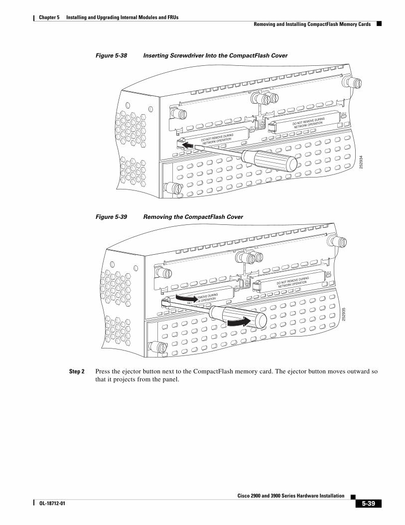
Step 1 Remove the CompactFlash cover by placing a flat screwdriver in the slot and pushing sideways against the tension to release the cover door. (See Figure 5-39 and Figure 5-39.)
5-39Cisco 2900 and 3900 Series Hardware Installation
OL-18712-01
Chapter 5 Installing and Upgrading Internal Modules and FRUs Removing and Installing CompactFlash Memory Cards
Figure 5-38 Inserting Screwdriver Into the CompactFlash Cover
Figure 5-39 Removing the CompactFlash Cover
Step 2 Press the ejector button next to the CompactFlash memory card. The ejector button moves outward so that it projects from the panel.
CF 1
CF 0
DO NOT REMOVE DURING
NETWORK OPERATION
DO NOT REMOVE DURING
NETWORK OPERATION
2529
34
CF 1
CF 0
DO NOT REMOVE DURING
NETWORK OPERATION
DO NOT REMOVE DURING
NETWORK OPERATION
2529
35

5-40Cisco 2900 and 3900 Series Hardware Installation
OL-18712-01
Chapter 5 Installing and Upgrading Internal Modules and FRUs Removing and Installing CompactFlash Memory Cards
Figure 5-40 CompactFlash Memory Card Slot in Cisco 2900 Series Routers
Step 3 Press the ejector button again. See Figure 5-40. This ejects the CompactFlash memory card part-way out of its slot.
Step 4 Pull the CompactFlash memory card out of its slot.
Step 5 Push the ejector button in until the button is flush with the bezel.
Caution To prevent damage to the ejector mechanism, the ejector button must remain pressed all the way in (flush against the bezel) when not being used to eject a CompactFlash memory card.
Installing a CompactFlash Memory CardTo install a CompactFlash memory card, perform the following steps (see Figure 5-40):
Step 1 Make sure that the ejector button is fully seated until it is flush with the bezel.
Note If the ejector button is projecting out from the panel, push it in until it is flush with the bezel.
Step 2 Insert the CompactFlash memory card into the slot until it is fully seated. The ejector button remains flush with the panel.
Note If the ejector button is projecting from the panel after you insert the CompactFlash memory card, remove the CompactFlash memory card, press the ejector button until it clicks, and reinsert the CompactFlash memory card.
Caution To prevent damage to the ejector mechanism, the ejector button must remain fully seated when not being used to eject a CompactFlash memory card.
Step 3 Replace the CompactFlash cover by inserting the cover lip into the chassis then pushing the over to snap it back into place.
DO NOT REMOVE DURING NETWORK OPERATION
DO NOT REMOVE DURING NETWORK OPERATION
CF 1
CF 0
2522
99
DO NOT REMOVE DURING NETWORK OPERATION
12

5-41Cisco 2900 and 3900 Series Hardware Installation
OL-18712-01
Chapter 5 Installing and Upgrading Internal Modules and FRUs Installing SFP Modules
Installing SFP ModulesThis section describes how to install optional small-form-factor pluggable (SFP) modules in Cisco 2900 and Cisco 3900 series integrated services routers to provide optical Gigabit Ethernet connectivity.
The SFP module installs into a slot on the router’s rear panel. When selected in Cisco IOS software, it is assigned port gigabitethernet 0/0. The default is the built-in RJ-45 1000Base-T connector, which is enabled on this port.
Only SFP modules certified by Cisco are supported on Cisco 2900 series and Cisco 3900 series routers. Table 5-5 on page 5-41 lists supported SFPs on Cisco 2900 and 3900 ISRs.
Consult the appropriate document for compatibility issues. See Cisco Transceiver Modules
Compatibility Information on Cisco.com.
Table 5-5 SFPs Supported on Cisco 2900 and 3900 Series Routers
Cisco Model Number SFP TransceiverFiber Diameter (micrometer)
Wavelength (nm) Mode
Maximum Distance
GLC-SX-MM= 1000Base-SX 50 850 Multi 550 m
GLC-LH-SM= 1000Base-LX/LH 9/125 1310 Single 10 km
GLC-ZX-SM= 1000Base-ZX 9/125 1550 Single 100 km
CWDM-SFP-1470= 1000Base-CWDM 50 1470 Single 100 km
CWDM-SFP-1490= 1490
CWDM-SFP-1510= 1510
CWDM-SFP-1530= 1530
CWDM-SFP-1550= 1550
CWDM-SFP-1570= 1570
CWDM-SFP-1590= 1590
CWDM-SFP-1610= 1610
DWDM-SFP-3033 1000BASE-DWDM 1530.33
DWDM-SFP-3112 1000BASE-DWDM 1531.12
DWDM-SFP-3190 1000BASE-DWDM 1531.90
DWDM-SFP-3268 1000BASE-DWDM 1532.68
DWDM-SFP-3425 1000BASE-DWDM 1534.25
DWDM-SFP-3504 1000BASE-DWDM 1535.04
DWDM-SFP-3582 1000BASE-DWDM 1535.82
DWDM-SFP-3661 1000BASE-DWDM 1536.61
DWDM-SFP-3819 1000BASE-DWDM 1538.19
DWDM-SFP-3898 1000BASE-DWDM 1539.77
DWDM-SFP-3977 1000BASE-DWDM 1539.98
DWDM-SFP-4056 1000BASE-DWDM 1540.56
DWDM-SFP-4214 1000BASE-DWDM 1542.14
DWDM-SFP-4294 1000BASE-DWDM 1542.94

5-42Cisco 2900 and 3900 Series Hardware Installation
OL-18712-01
Chapter 5 Installing and Upgrading Internal Modules and FRUs Installing SFP Modules
Tip Use the show controller command at the Cisco IOS prompt to determine whether you are using an SFP certified by Cisco.
DWDM-SFP-4373 1000BASE-DWDM 1543.73
DWDM-SFP-4453 1000BASE-DWDM 1544.53
DWDM-SFP-4612 1000BASE-DWDM 1546.12
DWDM-SFP-4692 1000BASE-DWDM 1546.92
DWDM-SFP-4772 1000BASE-DWDM 1547.72
DWDM-SFP-4851 1000BASE-DWDM 1548.51
DWDM-SFP-5012 1000BASE-DWDM 1550.12
DWDM-SFP-5092 1000BASE-DWDM 1550.92
DWDM-SFP-5172 1000BASE-DWDM 1551.72
DWDM-SFP-5252 1000BASE-DWDM 1552.52
DWDM-SFP-5413 1000BASE-DWDM 1554.13
DWDM-SFP-5494 1000BASE-DWDM 1554.94
DWDM-SFP-5575 1000BASE-DWDM 1555.75
DWDM-SFP-5655 1000BASE-DWDM 1556.55
DWDM-SFP-5817 1000BASE-DWDM 1558.17
DWDM-SFP-5898 1000BASE-DWDM 1558.98
DWDM-SFP-5979 1000BASE-DWDM 1559.79
DWDM-SFP-6061 1000BASE-DWDM 1560.61
GLC-BX-D 1490 TX
1310 RX
GLC-BX-U 1310 TX
1490 RX
GLC-FE-100FX 1310 Multi 2 km
GLC-FE-100LX 1310 Single 10 km
GLC-FE-100EX 100BASE-FX 1310 Single 40 km
GLC-FE-100ZX 100BASE-ZX 1550 Single 80 km
GLC-FE-100BX-U 1310 TX Single 10 km
1550 RX
GLC-FE-100BX-D 1550 TX Single 10 km
1310 RX
GLC-GE-100FX 1310 Multi 2 km
Table 5-5 SFPs Supported on Cisco 2900 and 3900 Series Routers
Cisco Model Number SFP TransceiverFiber Diameter (micrometer)
Wavelength (nm) Mode
Maximum Distance

5-43Cisco 2900 and 3900 Series Hardware Installation
OL-18712-01
Chapter 5 Installing and Upgrading Internal Modules and FRUs Installing SFP Modules
Laser Safety GuidelinesOptical SFPs use a small laser to generate the fiber-optic signal. Keep the optical transmit and receive ports covered whenever a cable is not connected to the port.
Warning Because invisible laser radiation may be emitted from the aperture of the port when no fiber cable is connected, avoid exposure to laser radiation and do not stare into open apertures.
Warning Ultimate disposal of this product should be handled according to all national laws and regulations.
Follow these steps to install an SFP module in a Cisco 2900 or 3900 series router:
Warning Because invisible laser radiation may be emitted from the aperture of the port when no fiber cable is connected, avoid exposure to laser radiation and do not stare into open apertures.
Step 1 Slide the SFP into the router connector until it locks into position (see Figure 5-41).
Tip If the SFP uses a bale-clasp latch (see Figure 5-41), the handle should be on top of the SFP module.
Figure 5-41 Installing an SFP Module
Caution Do not remove the optical port plugs from the SFP until you are ready to connect cabling.
Step 2 Connect the network cable to the SFP module.
Removing SFP ModulesFollow these steps to remove an SFP from a Cisco 2900 series or Cisco 3900 series router:
Step 1 Disconnect all cables from the SFP.
9412
6

5-44Cisco 2900 and 3900 Series Hardware Installation
OL-18712-01
Chapter 5 Installing and Upgrading Internal Modules and FRUs Installing SFP Modules
Warning Because invisible laser radiation may be emitted from the aperture of the port when no fiber cable is connected, avoid exposure to laser radiation and do not stare into open apertures.
Caution The latching mechanism used on many SFPs locks the SFP into place when cables are connected. Do not pull on the cabling in an attempt to remove the SFP.
Step 2 Disconnect the SFP latch. See Figure 5-42.
Note SFP modules use various latch designs to secure the module in the SFP port. Latch designs are not linked to SFP model or technology type. For information on the SFP technology type and model, see the label on the side of the SFP.
Figure 5-42 Disconnecting SFP Latch Mechanisms
Tip Use a pen, screwdriver, or other small straight tool to gently release a bale-clasp handle if you cannot reach it with your fingers.
Step 3 Grasp the SFP on both sides and remove it from the router.
1 Sliding latch 3 Bale-clasp latch
2 Swing and slide latch 4 Plastic collar latch
1177
22
1 2 3 4
A
B
C H A P T E R
6-1Cisco 2900 and 3900 Series Hardware Installation
OL-18712-01
6Getting Software Licenses for the Router
The Integrated Services Router Generation 2 (ISR G2) platforms offer a new Universal Cisco Internet Operating System (IOS) software image. The Universal image and its licensing provisions provide greater flexibility to deploy new features while also improving visibility and management of existing licenses on routers in the network.
When you order a new ISR G2, it is shipped with the software image and the corresponding permanent licenses for the packages and features that you specified, preinstalled. The software does not need to be activated or registered prior to use.
Use the Cisco management application such as Cisco License Manager (CLM), or use the Cisco IOS command show license feature to determine the licenses activated on your system. CLM is a free software application available at http://www.cisco.com/go/clm.
Your The router comes with an evaluation license, also known as a temporary license, for most packages and features supported on the router. To try a new software package or feature, activate the evaluation license for that package or feature.
Activating a New Software Package or FeatureComplete the following steps to permanently activate a software package or feature on the your router:
Step 1 Purchase the software package or feature you want to install. You will receive a product activation key (PAK) with your purchase.
Step 2 If you do not have a Cisco.com username and password, register for an account at the following URL, https://tools.cisco.com/RPF/register/register.do.
Step 3 Get the license file using one of the following options:
Note You will require the serial number (SN) and product ID (PID) of the router where the license should be installed. See the Locating the Serial Number, PID, VID and CLEI, page 1-11 for the location of the SN and PID.
• Cisco License Manager (CLM) - CLM is a free software application available at http://www.cisco.com/go/clm.
• Cisco License Registration Portal - Cisco license registration portal is a web-based portal for getting and registering individual software licenses, available at http://www.cisco.com/go/license

6-2Cisco 2900 and 3900 Series Hardware Installation
OL-18712-01
Chapter 6 Getting Software Licenses for the Router RMA License Transfer
• Cisco License Call Home - Use the Cisco License Call Home interface on the router to directly interact with the Cisco Product License Registration portal.
Step 4 Install the license file using one of the following options:
• Cisco License Manager (CLM) - CLM is a free software application available at http://www.cisco.com/go/clm.
• Cisco License Call Home - Use the Cisco License Call Home interface on the router to directly interact with the Cisco Product License Registration portal.
• Cisco IOS CLI - Use the Cisco IOS command line interface (CLI) to install and manage licenses.
• Simple Network Management Protocol (SNMP) - Use SNMP to install and manage software licenses.
Figure 1 - shows the steps for software activation.
Figure 1 Steps for Software Activation
RMA License TransferTo transfer a software license from a failed device to a new device, go to the Cisco licensing portal at http://www.cisco.com/go/license.
Note You will need the SN and PID of the defective device, as well as the RMA router to initiate an RMA replacement license.
1
2
3
Purchase a Package or Feature
Receive a PAK
Obtain a License.A PAK and UDI is required
Cisco License ManagerOption 1
Option 2
Option 3
Cisco License PortalHttp://www.cisco.com
Cisco Call Home
ReceiveLicense File
Install License27
5364

6-3Cisco 2900 and 3900 Series Hardware Installation
OL-18712-01
Chapter 6 Getting Software Licenses for the Router Additional Information
Additional InformationSee the Software Activation on Cisco Integrated Services Routers and Cisco Integrated Service Routers Generation 2 document on Cisco.com for detailed information on about software activation on Cisco ISR G2 platforms.

6-4Cisco 2900 and 3900 Series Hardware Installation
OL-18712-01
Chapter 6 Getting Software Licenses for the Router Additional Information
A-1Cisco 2900 and 3900 Series Hardware Installation
OL-18712-01
A P P E N D I X AOnline Insertion Removal and Hot-Swapping
Online Insertion and Removal and Hot-SwappingOnline insertion and removal (OIR) enables you to replace faulty modules without affecting system operation, this is similar to hot-swapping. OIR commands must be issued before removing a module and after installing a module. When performing OIR, an identical module must be used to replace the original. If performing OIR on multiple modules within a router, perform the operation on one module at a time.
The module must be in energywise full-power mode for OIR commands to be issued. If the module is in energywise power-saving or shutdown mode, OIR commands can not be issued, and the module should not be removed.
Note OIR is only supported on the Cisco 3925 and Cisco 3945 ISRs.
The difference between hot-swapping and OIR is that OIR requires performing IOS commands before and after the OIR. Hot-swapping is strictly a hardware function and requires no commands. Not all router components or modules use OIR, or can be hot swapped.
The following items use OIR in the Cisco 3925 and Cisco 3945 ISRs:
• Service modules
• Network modules
Note Network modules must be inserted into a network module adapter. The network module adapter and network module must always remain together. They function as one unit.
• External CompactFlash memory
• SFPs
• USB devices
The following items can be hot swapped:
• Fan tray
• Power supply only when the router is backed up with an RPS
A-2Cisco 2900 and 3900 Series Hardware Installation
OL-18712-01
Appendix A Online Insertion Removal and Hot-Swapping OIR Procedures
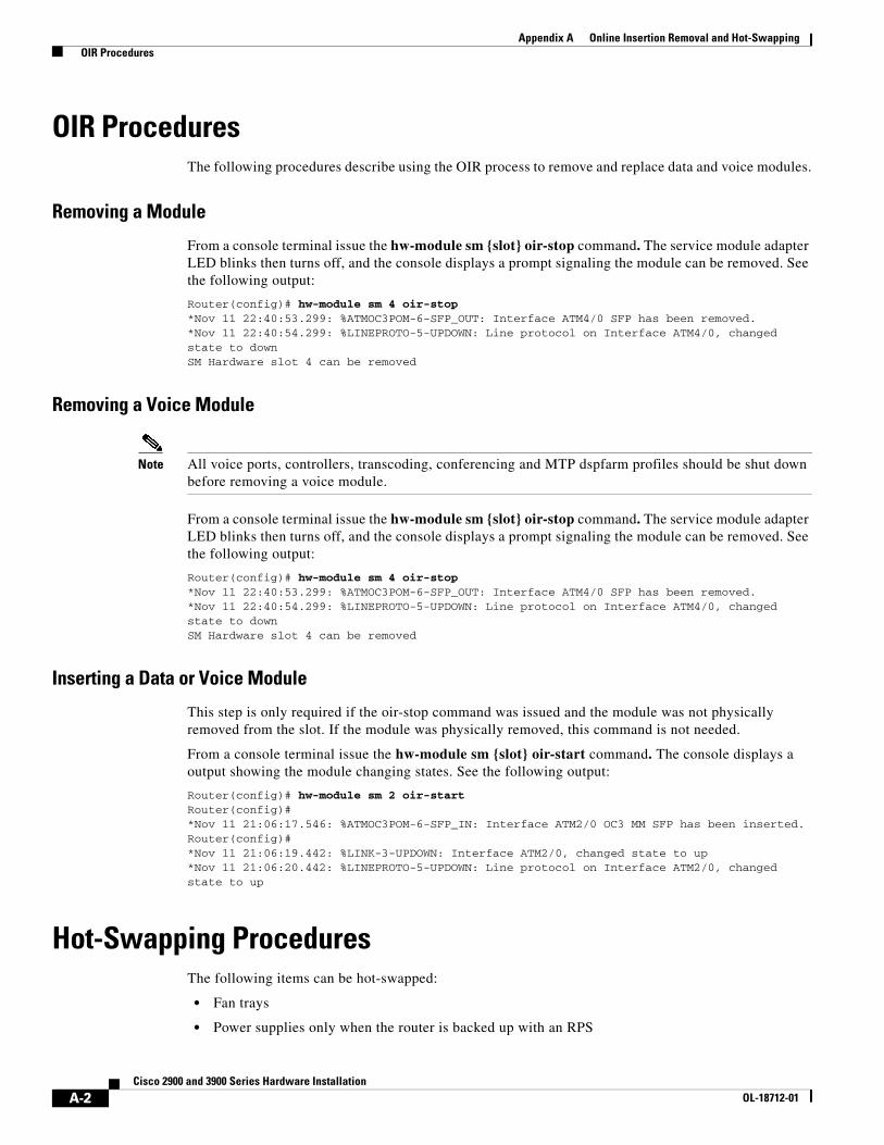
OIR ProceduresThe following procedures describe using the OIR process to remove and replace data and voice modules.
Removing a Module
From a console terminal issue the hw-module sm {slot} oir-stop command. The service module adapter LED blinks then turns off, and the console displays a prompt signaling the module can be removed. See the following output:
Router(config)# hw-module sm 4 oir-stop*Nov 11 22:40:53.299: %ATMOC3POM-6-SFP_OUT: Interface ATM4/0 SFP has been removed. *Nov 11 22:40:54.299: %LINEPROTO-5-UPDOWN: Line protocol on Interface ATM4/0, changed state to downSM Hardware slot 4 can be removed
Removing a Voice Module
Note All voice ports, controllers, transcoding, conferencing and MTP dspfarm profiles should be shut down before removing a voice module.
From a console terminal issue the hw-module sm {slot} oir-stop command. The service module adapter LED blinks then turns off, and the console displays a prompt signaling the module can be removed. See the following output:
Router(config)# hw-module sm 4 oir-stop*Nov 11 22:40:53.299: %ATMOC3POM-6-SFP_OUT: Interface ATM4/0 SFP has been removed. *Nov 11 22:40:54.299: %LINEPROTO-5-UPDOWN: Line protocol on Interface ATM4/0, changed state to downSM Hardware slot 4 can be removed
Inserting a Data or Voice Module
This step is only required if the oir-stop command was issued and the module was not physically removed from the slot. If the module was physically removed, this command is not needed.
From a console terminal issue the hw-module sm {slot} oir-start command. The console displays a output showing the module changing states. See the following output:
Router(config)# hw-module sm 2 oir-startRouter(config)#*Nov 11 21:06:17.546: %ATMOC3POM-6-SFP_IN: Interface ATM2/0 OC3 MM SFP has been inserted. Router(config)# *Nov 11 21:06:19.442: %LINK-3-UPDOWN: Interface ATM2/0, changed state to up *Nov 11 21:06:20.442: %LINEPROTO-5-UPDOWN: Line protocol on Interface ATM2/0, changed state to up
Hot-Swapping ProceduresThe following items can be hot-swapped:
• Fan trays
• Power supplies only when the router is backed up with an RPS

A-3Cisco 2900 and 3900 Series Hardware Installation
OL-18712-01
Appendix A Online Insertion Removal and Hot-Swapping Hot-Swapping Procedures
See “Replacing a Fan Tray or Air Filter” section on page 5-31 and “Replacing Power Supplies and Redundant Power Supplies” section on page 5-23.

A-4Cisco 2900 and 3900 Series Hardware Installation
OL-18712-01
Appendix A Online Insertion Removal and Hot-Swapping Hot-Swapping Procedures


