29. Diffraction of waves - Brown University...Diffraction of a wave by a slit Passing light through...
22
29. Diffraction of waves Light bends! Diffraction assumptions The Kirchhoff diffraction integral Fresnel Diffraction diffraction from a slit
Transcript of 29. Diffraction of waves - Brown University...Diffraction of a wave by a slit Passing light through...

29. Diffraction of waves
Light bends!
Diffraction assumptions
The Kirchhoff diffraction
integral
Fresnel Diffraction
diffraction from a slit
Diffraction
Light does not
always travel in
a straight line.
It tends to bend
around objects.
This tendency is
called "diffraction.“
Shadow of a
razor blade
illuminated by
a laser
This is why radio communications does
not necessarily require a line of sight.

Diffraction of Ocean Water Waves
Ocean waves passing through, and bending around the edges of, slits (regions between wave brakes) in Tel Aviv, Israel:
Diffraction occurs for all waves, whatever the phenomenon.

Diffraction of a wave by a slit
Passing light through a small slit yields a diffraction pattern that depends on the size of the slit and the wavelength of the wave.
This phenomenon is general, and can be observed using waves of any kind.
Large slit
Smaller slit
Very small slit

C. J. Davisson and
L. H. Germer, 1927
Diffraction of particles
This experiment was completed only a
few years after Louis de Broglie had
described the wavelength of a particle in terms of its momentum, λ = h/p.
(h = Planck’s constant)
Electrons do this too. The observation of this fact was one of the first important confirmations of quantum physics.
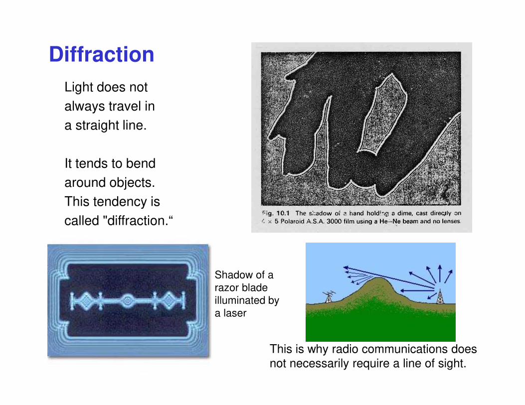
What is E(x0,y0) at a distance z from the plane of the aperture?
This region is assumed to be
much smaller than this one.
We wish to find the light electric field after a screen with a hole in it.This is a very general problem with far-reaching implications.
The Diffraction Problem
(x1, y1)
incident plane wave
plane of the
aperture
z
observation
plane
( ) ( )2 22
01 0 1 0 1= + − + −r z x x y y
(x0, y0)
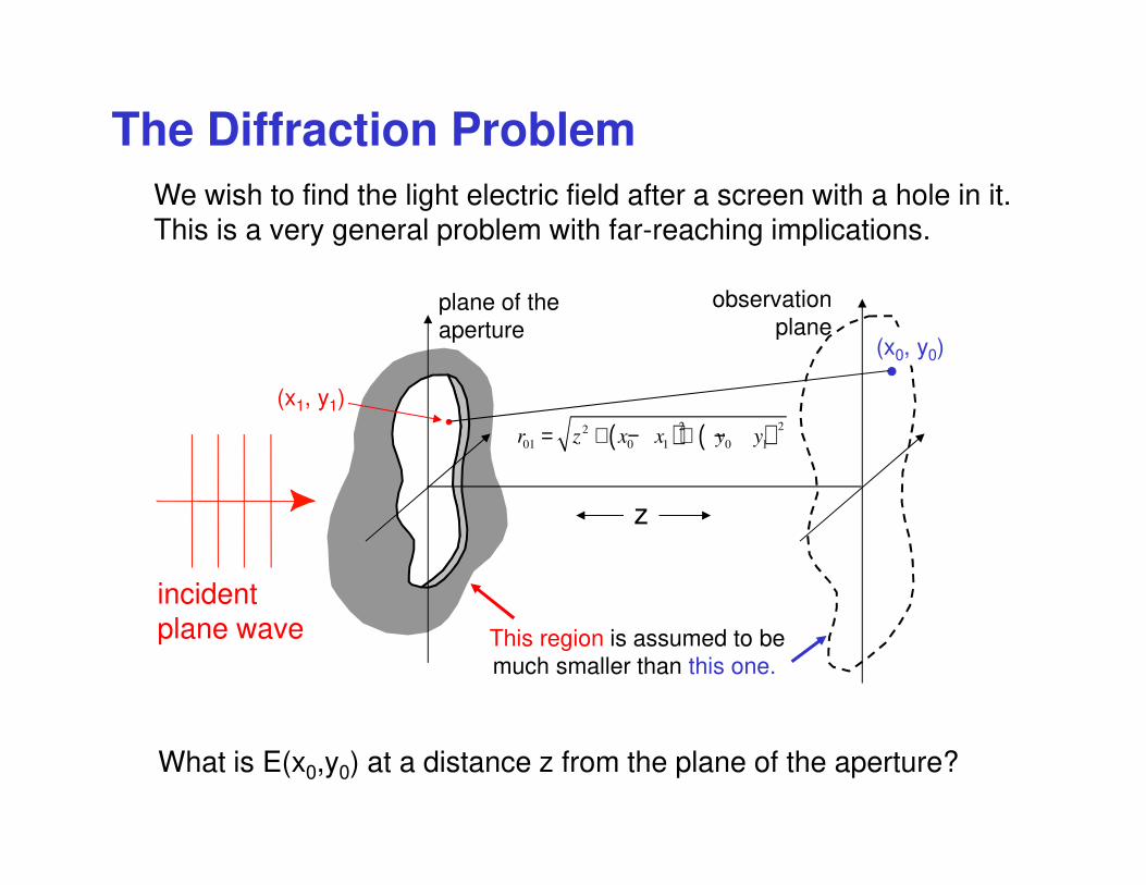
Diffraction Assumptions
This set of assumptions actually over-determines the problem. But even so, this is a useful starting point. A more accurate treatment is very complicated!
The first thorough treatment of this problem was due to Kirchhoff. He made a few assumptions:
Gustav R. Kirchhoff
(1824 - 1887)
1) Maxwell's equations
2) Inside the aperture at z = 0, the field and its spatial derivative are the same as if the screen were not present.
3) Outside the aperture (in the shadow of the screen) at z = 0, the field and its spatial derivative are zero.
Incident wave
( , )E r t�
( , )E r t∇�
�
( , ) 0E r t =�
( , ) 0E r t∇ =�
�
( , ) 0E r t =�
( , ) 0E r t∇ =�
�
z0

Huygens’ Principle
Our solution for diffraction uses this idea.
Christiaan Huygens
1629 – 1695
Huygens’ Principle says that every point along a wave-front emits a spherical wave that interferes with all others.

Incident field
A solution based on Huygen’s principle
(x1, y1)
Huygen’s wavelet
z
(x0, y0)r01( ) ( )2 22
01 0 1 0 1= + − + −r z x x y y
Each point (x1, y1) in the aperture emits a spherical wave, with amplitude determined by the wave incident on the aperture.
The net field at the point (x0, y0) is therefore given by a superposition:
( ) ( ) ( )1 1
0 0 01 1 1
all points (x ,y ) in the aperture
, spherical wave propagating a distance r incident field at x ,y= ×∑E x y
Of course, the sum becomes an integral…
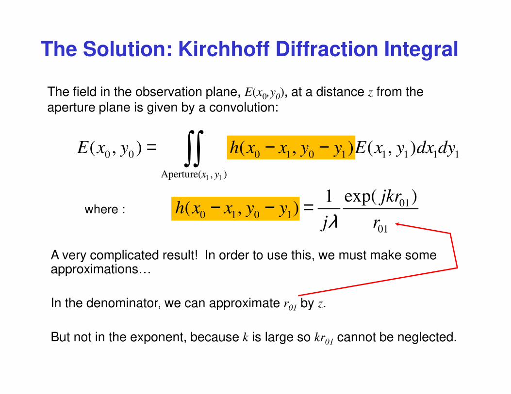
The Solution: Kirchhoff Diffraction Integral
The field in the observation plane, E(x0,y0), at a distance z from the
aperture plane is given by a convolution:
1 1
0 0 0 1 0 1 1 1 1 1
Aperture( , )
( , ) ( , ) ( , )= − −∫∫x y
E x y h x x y y E x y dx dy
010 1 0 1
01
exp( )1 ( , )
jkrh x x y y
j rλ− − =where :
A very complicated result! In order to use this, we must make some approximations…
In the denominator, we can approximate r01 by z.
But not in the exponent, because k is large so kr01 cannot be neglected.

Paraxial approximation
In the spirit of the paraxial approximation, we will assume that the aperture is small compared to the distance z, so that z >> x0 − x1 and y0 − y1.
2 2
0 1 0 101 1
− − = + +
x x y yr z
z z
First, we note that we can factor z out of the square root in the expresson for r01:
( ) ( )2 22 2
0 1 0 10 1 0 101
1 11 small corrections
2 2 2 2
− −− − ≈ + + = + + = +
x x y yx x y yr z z z
z z z z
Make use of the Taylor expansion:1
1 12
+ ≈ +ε ε
( ) ( ) ( )2 2
0 1 0 1
0 1 0 1
exp exp exp2 21
( , )
x x y yjkz jk jk
z zh x x y y
j zλ
− − − − ≈
Replace r01 in the exponent of h(x0−x1, y0−y1):

( ) ( )
1 1
2 2
0 1 0 1
0 0 1 1 1 1
( , )
1( , ) exp ( , )
2 2
− − ≈ + + ∫∫
Aperture x y
x x y yE x y jk z E x y dx dy
j z z zλ
( )1 1
2 2 2 2
0 0 1 1 0 0 1 10 0 1 1 1 1
( , )
( 2 ) ( 2 ), exp ( , )
2 2
− + − + = + ∫∫
jkz
Aperture x y
x x x x y y y yeE x y jk E x y dx dy
j z z zλ
Multiplying out the squares, and factoring out the constants:
Thus, we have:
Paraxial approximation: Fresnel diffraction
If the incident wave is a plane wave, as is typically assumed, then:
1 1( , ) constant=E x y
(constant with respect to x1 and y1)

The Fresnel Diffraction Integral
And we’ll usually neglect the factors in front of the integral, to obtain:
( )2 2
0 1 0 1 1 10 0 1 1 1 1
( 2 2 ) ( ), exp (x , )
2 2
− − + ∝ + ∫∫
x x y y x yE x y jk Aperture y dx dy
z z
This is the Fresnel Diffraction integral. Even with all the approximations we’ve made, it is usually difficult to evaluate.
Usually, instead of writing an integral over an aperture, we will explicitly write the aperture function in the integral:
( ) ( )2 2 2 2
0 0 0 1 0 1 1 10 0 1 1 1 1
( 2 2 ) ( ), exp exp ,
2 2
inE x y x x y y x yE x y jk z jk Aperture x y dx dy
j z z z z
+ − − + = + + ∫∫λ

Consider a uniform plane wave incident on a metal screen with a slit of width 2b in the x1-direction. A one-dimensional problem, this may be the simplest of all possible diffraction problems.
It’s still not easy.
2b
Before solving it, let’s first try to anticipate what we might expect the answer to look like.
observ
atio
n s
cre
en
Destructive interference when the path length difference is λ/2, 3λ/2, 5λ/2, etc.
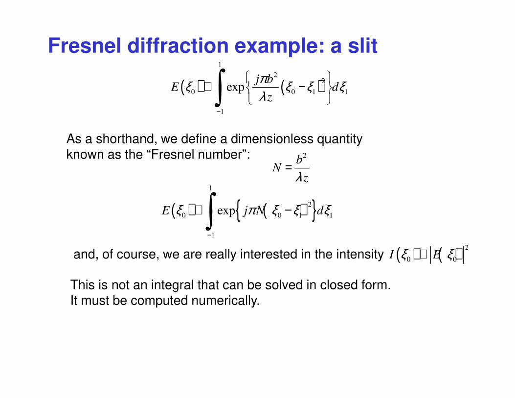
Fresnel diffraction example: a slit
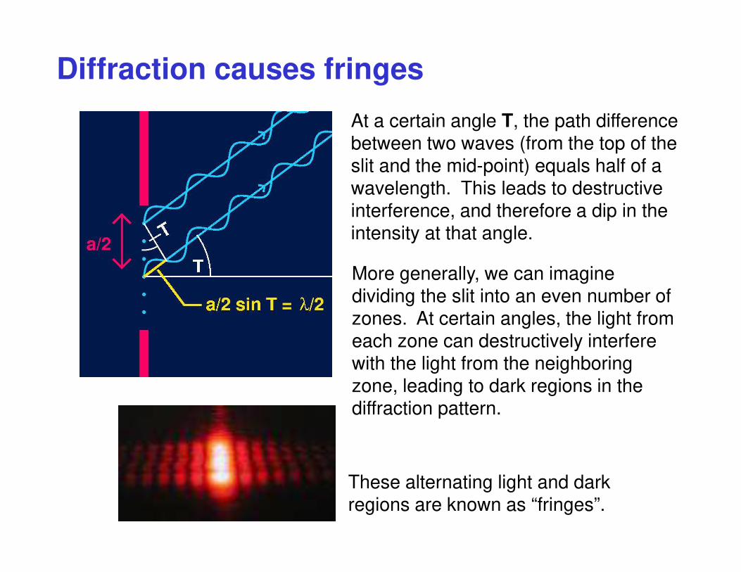
At a certain angle T, the path difference between two waves (from the top of the slit and the mid-point) equals half of a wavelength. This leads to destructive interference, and therefore a dip in the intensity at that angle.
Diffraction causes fringes
More generally, we can imagine dividing the slit into an even number of zones. At certain angles, the light from each zone can destructively interfere with the light from the neighboring zone, leading to dark regions in the diffraction pattern.
These alternating light and dark regions are known as “fringes”.

Write the Fresnel integral for this one-dimensional problem:
Next step: define new variables and11 = x
bξ 0
0 = x
bξ
( ) ( ) ( )1
22
0 0 0 1 1
1
expj b
E x E dz
πξ ξ ξ ξλ
−
→ ∝ −
∫Then:2=kπλ
since
( ) ( )2 2
0 0 1 10 1 1
2exp
2
x x x xE x jk Aperture x dx
z
− + ∝ ∫
Fresnel integral for a slit
The aperture function is given by: ( ) 1
1
1
0 otherwise
b x bAperture x
− < <=
( ) ( )2
0 1
0 1exp2
−
− = ∫
b
b
x xE x jk dx
zThus the integral becomes:
Fresnel diffraction example: a slit
( ) ( )1
22
0 0 1 1
1
expj b
E dz
πξ ξ ξ ξλ
−
∝ −
∫As a shorthand, we define a dimensionless quantity known as the “Fresnel number”: 2
= bN
zλ
( ) ( ){ }1
2
0 0 1 1
1
expE j N dξ π ξ ξ ξ
−
∝ −∫
This is not an integral that can be solved in closed form. It must be computed numerically.
and, of course, we are really interested in the intensity ( ) ( ) 2
0 0I Eξ ξ∝

Fresnel Diffraction from a Slit (cont’d)
The irradiance vs. position for different distances from the slit:
Far
from
the
slit
zClose
to the
slit
Incident plane wave
Slit I(x’,z)

Fresnel Diffraction through a slit: numerical results for I(ξ0)
Far from the slit:
Closer to the slit:
Fresnel number N
0.5
1
2
4
8
10
20
2
= bN
zλFresnel number:
Example: green light (λ = 0.5 µm)
a) slit width b = 1 millimeter = 2000λ
N = 1 at a distance of 2 meters
b) slit width b = 10 microns = 20λ
N = 1 at a distance of 200 µm
# of ripples ~ Fresnel number!
-2b 2b
Recall: this Fresnel calculation is only
valid for z >> b, which is the paraxial
approximation.

Fresnel Diffraction through a slit: far field
( ) ( ){ }1
2
0 0 1 1
1
expE j N dξ π ξ ξ ξ
−
∝ −∫In the limit that N << 1 (very far from the aperture), the integral can be performed analytically. The math is a bit tedious, so we just quote the result here:
( )0
00
2sin
2
∝
Nx
bE x
Nx
b
π
πOur old friend the sinc function!
In this regime (the “far field”), the diffraction pattern no longer changes shape as z increases, but merely expands in size uniformly.
Fresnel number
0.03
0.02
0.01
-100b 100b

Fuzzy shadow edges make it hard to see diffraction.
An incident plane wave or spherical wave (which, like a plane wave, has a flat and well-behaved wave front) is required to see diffraction.
Here, rays from a
point source yield, in
principle, a perfect
shadow of the hole,
allowing diffraction
ripples to be seen.
Screenwith slit
In general, a large source (like the sun or a light bulb) casts blurry shadows, masking the diffraction ripples.
Rays from other
regions of the source
blur the shadow.
A large source masks diffraction effects.

Fresnel Diffraction through a slit: isn’t there an awesome java applet that illustrates all this?
http://www.falstad.com/ripple/
More than one, actually
http://www.falstad.com/diffraction/