28 Volt input – 15 amp not recommenDeD For new Design · • Compatible with MIL-STD-704 A-E 28...
13
DESCRIPTION The Interpoint® FME28-461 Series™ of EMI filters offers up to 15 amps of throughput current in a low profile package. The FME28-461 filters are manufactured in our fully certified and qualified MIL-PRF-38534 Class H production facility and packaged in hermetically sealed steel cases. They are ideal for use in programs requiring high reliability and small size. These EMI filters are specifically designed to reduce the reflected input ripple current of Interpoint’s high frequency DC-DC converters. FME filters minimize electromagnetic interference (EMI) for the MOR, MFL, MFX, MWR, MTR, MFK, MHV, MHF+, MSA and MCH. Series of converters. These filters are intended for use in 28 volt applications which must meet MIL-STD-461C CE03 levels of conducted emissions. One filter can be used with multiple converters up to the rated output current of the filter. INPUT RIPPLE AND EMI Switching DC-DC converters naturally generate two noise components on the power input line: differential noise and common mode noise. Input ripple current refers to both of these components. Differential noise occurs between the positive input and input common. Most Interpoint converters have an input filter that reduces differential noise which is sufficient for many applications. Common mode noise occurs across stray capacitances between the converter’s power train components and the baseplate (bottom of the package) of the converter. Where low noise currents are required to meet MIL-STD-461C, a power line filter is needed. The FME28 EMI power line filters reduces the common mode and differential noise generated by the converters. FME28 filters reduce input ripple current to a minimum of 60 dB at 500 kHz and 1 MHz when used in conjunction with Interpoint DC-DC converters. Place the filter as close as possible to the converter for optimum performance. The baseplates of the filter and the converter should be connected with the shortest and widest possible conductors. TRANSIENTS A transient of -100 to +100 V for up to 100 ms with a 0.5 ohm source impedance will not damage the filter but will be passed on to the converter: OPERATION OVER TEMPERATURE The FME28-461 Series filters are rated for operation from -55°C to +125°C case temperature. INSERTION LOSS The maximum dc insertion loss at full load and nominal input voltage represents a power loss of less than 4%. PACKAGING FME28-461 filters are sealed in metal hermetic side-leaded packages. See cases U, V, W, Y, and Z. FEATURES • Attenuation to a minimum of 60 dB at 500 kHz • Operating temperature -55° to +125°C • Nominal 28 V input, 0 to 50 V operation • Transient rating to ±100 V for 100 ms • Up to 15 A throughput current • Screening up to Class H (/883) of MIL-PRF-38534 • Compliant to MIL-STD-461C, CE03 • Compatible with MIL-STD-704 A-E 28 VDC power bus FME28-461 INPUT (V) CURRENT (A) 0 - 50 15 NOT RECOMMENDED FOR NEW DESIGN Crane Aerospace & Electronics Power Solutions FME28-461 EMI Input Filters Crane Aerospace & Electronics Power Solutions – Interpoint Products 10301 Willows Rd. NE, Redmond, WA 98052 +1 425.882.3100 • [email protected] www.craneae.com/interpoint Page 1 of 13 28 VOLT INPUT – 15 AMP FME28-461 Rev AA - 2017.10.13
Transcript of 28 Volt input – 15 amp not recommenDeD For new Design · • Compatible with MIL-STD-704 A-E 28...

DescriptionThe Interpoint® FME28-461 Series™ of EMI filters offers up to 15 amps of throughput current in a low profile package. The FME28-461 filters are manufactured in our fully certified and qualified MIL-PRF-38534 Class H production facility and packaged in hermetically sealed steel cases. They are ideal for use in programs requiring high reliability and small size. These EMI filters are specifically designed to reduce the reflected input ripple current of Interpoint’s high frequency DC-DC converters. FME filters minimize electromagnetic interference (EMI) for the MOR, MFL, MFX, MWR, MTR, MFK, MHV, MHF+, MSA and MCH. Series of converters. These filters are intended for use in 28 volt applications which must meet MIL-STD-461C CE03 levels of conducted emissions. One filter can be used with multiple converters up to the rated output current of the filter.
Input RIpple and eMISwitching DC-DC converters naturally generate two noise components on the power input line: differential noise and common mode noise. Input ripple current refers to both of these components. Differential noise occurs between the positive input and input common. Most Interpoint converters have an input filter that reduces differential noise which is sufficient for many applications. Common mode noise occurs across stray capacitances between the converter’s power train components and the baseplate (bottom of the package) of the converter.
Where low noise currents are required to meet MIL-STD-461C, a power line filter is needed. The FME28 EMI power line filters reduces the common mode and differential noise generated by the converters. FME28 filters reduce input ripple current to a minimum of 60 dB at 500 kHz and 1 MHz when used in conjunction with Interpoint DC-DC converters.
Place the filter as close as possible to the converter for optimum performance. The baseplates of the filter and the converter should be connected with the shortest and widest possible conductors.
tRansIentsA transient of -100 to +100 V for up to 100 ms with a 0.5 ohm source impedance will not damage the filter but will be passed on to the converter:
OpeRatIOn OveR teMpeRatuReThe FME28-461 Series filters are rated for operation from -55°C to +125°C case temperature.
InseRtIOn lOssThe maximum dc insertion loss at full load and nominal input voltage represents a power loss of less than 4%.
packagIngFME28-461 filters are sealed in metal hermetic side-leaded packages. See cases U, V, W, Y, and Z.
Features• Attenuation to a minimum of 60 dB at 500 kHz• Operating temperature -55° to +125°C• Nominal 28 V input, 0 to 50 V operation• Transient rating to ±100 V for 100 ms• Up to 15 A throughput current• Screening up to Class H (/883) of MIL-PRF-38534• Compliant to MIL-STD-461C, CE03• Compatible with MIL-STD-704 A-E 28 VDC power bus
FME28-461InPUT (V) CURREnT (A)
0 - 50 15
not recommenDeD For new Design
Crane Aerospace & Electronics Power Solutions
Fme28-461 emi input Filters
Crane Aerospace & ElectronicsPower Solutions – Interpoint Products10301 Willows Rd. NE, Redmond, WA 98052+1 425.882.3100 • [email protected]/interpoint
Page 1 of 13
28 Volt input – 15 amp
FME28-461 Rev AA - 2017.10.13

PositiveInput
InputCommon
PositiveOutput
OutputCommon
FME28-461
FIguRe 1: cOnnectIOn dIagRaM
+Vin +Vout
InputCommon
OutputCommon
Case R L
R L
EMI FILTER DC-DC CONVERTER+Vin +Vout
InputCommon
OutputCommon
Case
Chassisground
Multiple unitsallowed up torated output
current of filter
FIguRe 2: scheMatIc
The case ground connection between the filter and the converters should be aslow an impedance as possible to minimize EMI. Direct contact of baseplate tochassis ground provides the lowest impedance.
Crane Aerospace & Electronics Power Solutions
www.craneae.com/interpoint Page 2 of 13FME28-461 Rev AA - 2017.10.13
Fme28-461 emi input Filters28 Volt input – 15 amp

pin out
Angled corner and cover marking indicate pin one for cases U and V. Cover marking indicates pin one for cases W, Y and Z.
TOP VIEWU Case1
2
3
4
5
6
12
11
10
9
8
7
Outline shown is case U, pin out is the samefor all cases. See cases U, V, W, Y, and Z for dimensions.
notes1. All pins must be connected.2. The baseplate is the only case ground connection and
should directly contact chassis ground.
FIguRe 3: pIn Out
pin 1 Designation1, 2, 3 Positive Input4, 5, 6 Input Common7, 8, 9 Output Common
10, 11, 12 Positive Output— Case Ground 2
table 1: pIn Out
Crane Aerospace & Electronics Power Solutions
www.craneae.com/interpoint Page 3 of 13FME28-461 Rev AA - 2017.10.13
Fme28-461 emi input Filters28 Volt input – 15 amp

moDel numbering key
FME 28 - 461 V / 883 Base Model
Input VoltageMIL-STD-461 Reference
ScreeningCase/Lead Option*
(Standard screening has no designator in this position.)
Dla numbersDLA DrAwing (5915) FME28 SiMiLAr PArt
95004-01HTC FME28-461W/88395004-01HUC FME28-461V/88395004-01HXC FME28-461/88395004-01HYC FME28-461Y/88395004-01HZC FME28-461Z/883For exact specifications for a DLA product, refer to the DLA drawing. DLA drawings can be downloaded from: https://landandmaritimeapps.dla.mil/programs/smcr
*Case/Lead Option: See cases U, V, W, Y, and Z for drawings and dimensions.
case options: Dla cases cross referenced to interpoint cases
DLACase Option
Interpoint Case Option
Case Drawing Description
T w Figure 10 on page 9 tabbed, leads bent upU V Figure 9 on page 8 flanged, leads bent downX (standard case, no option required) Figure 8 on page 7 flanged, short leadsY y Figure 11 on page 10 tabbed, short leadsZ Z Figure 12 on page 11 tabbed, leads bent down
table 2: dla nuMbeR cROss ReFeRence
table 4: MOdel nuMbeR OptIOns
table 3: case OptIOns cROss ReFeRenced
FIguRe 3: MOdel nuMbeRIng key
moDel number options 1to DEtErMinE thE MoDEL nuMbEr EntEr onE oPtion FroM EAch cAtEgory in thE ForM bELow.
category base model and input Voltage
case option 2 screening 3
options Fme28-461
(flanged, short leads, standard “u” case, leave blank)
(Standard, leave blank)
V (flanged, leads bent down)w (tabbed, leads bent up)
y (tabbed, short leads)Z (tabbed, leads bent down)
ES883 (Class H)
Fill in For moDel # 4 Fme28-461__________ / notes:1. See Model Numbering Key above for an example of a model number. 2. Case Options: Case U is the standard case, leave the case option blank for case U. For case V, W, Y or Z, place the appropriate letter in the case option position. 3. Screening: See Table 7 on page 12 and Table 8 on page 13 for more information. Use “ES” for “ES” screening and “883” for Class H screening. “H” indicates
Class H of MIL-PRF-38534.4. If ordering by model number add a “-Q” to request solder dipped leads (FME28-461V/883-Q). Available only for Class H.
Crane Aerospace & Electronics Power Solutions
www.craneae.com/interpoint Page 4 of 13FME28-461 Rev AA - 2017.10.13
Fme28-461 emi input Filters28 Volt input – 15 amp

notes Table 5 and Table 61. Guaranteed by characterization test and/or analysis. not a production test.2. 0.5 ohm source impedance. 3. Transients up to 100 volts will not damage the filter but will be passed through the filter. 4. 15 A maximum at 95°C, derate linearly to 10 A at 125°C
MODEL FME28-461
PARAMETER CONDITIONS MIn TYP MAX UnITSInPUT VOLTAGE 1 COnTInUOUS 0 28 50 V
TRANSIENT 100 ms 2, 3 -100 — 100nOISE REJECTIOn 500 kHz 60 — — dB
1 MHz 60 — —DC RESISTANCE (RDC) TC = 25°C — — 0.076 ΩCAPACITAnCE 25°C AnY PIn TO CASE 50,000 60,000 70,000 pF
OUTPUT VOLTAGE 1 STEADY STATE VOUT = VIn - IIn (RDC) V
OUTPUT CURREnT 1, 4 STEADY STATE — — 15 APOWER DISSIPATION 1, 4
AT MAXIMUM CURREnT15 A, TC = 25°C — — 17.1 W10 A, TC = 125°C — — 10.8
table 5: OpeRatIng cOndItIOns, 28 vIn, 100% lOad, unless OtheRwIse specIFIed.
MODEL FME28-461PARAMETER CONDITIONS MIn TYP MAX UnITSLEAD SOLDERING TEMPERATURE 1 10 seconds max. — — 300 °CSTORAGE TEMPERATURE 1 -65 — +150 °C
CASE OPERATInG FULL POWER -55 — +125 °CTEMPERATURE 1 ABSOLUTE -55 — +135
DERATING OUTPUT POWER/CURRENT 1 LInEARLY From 15 A at 95°C to 10 A at 125°C
From 10 A at 125°C to 0 at 135°C
ISOLATIOn, AnY PIn TO CASE 500 VDC AT 25°C 100 — — Megohms
table 6: electRIcal chaRacteRIstIcs: -55 tO +125°c case, 28 vIn, unless OtheRwIse specIFIed.
Crane Aerospace & Electronics Power Solutions
www.craneae.com/interpoint Page 5 of 13FME28-461 Rev AA - 2017.10.13
Fme28-461 emi input Filters28 Volt input – 15 amp

FOR ReFeRence Only, nOt guaRanteed specIFIcatIOns.
FIguRe 4
FIguRe 6
thRee paRalleled and synchROnIzed MFl2815d cOnveRteRs wIthOut FIlteRIng.
FIguRe 5
FIguRe 7
ce03: thRee paRalleled and synchROnIzedMFl2815d cOnveRteRs wIth an FMe28-461.
FREQUENCY (MHz)
EMIS
SIO
N L
EVEL
(dB
A
0.1 1 10 50
90
80
70
60
50
40
30
20
10
0
.015
CE03 LIMIT
NARROWBAND
FREQUENCY (MHz)
EMIS
SIO
N L
EVEL
(dB
A)
0.1 1 10 50
90
80
70
60
50
40
30
20
10
0
.015
NARROWBANDCE03 LIMIT
FREQUENCY (kHz)1.0 10
3.6
2.7
1.8
0.9
0100
IMPE
DAN
CE
(OH
MS)
DC BIAS: 1 AMPFME28-461 OUTPUT IMPEDANCE
FREQUENCY (kHz)10
1.2
0.9
0.6
0.3
01 100
IMPE
DAN
CE
(OH
MS)
DC BIAS: 10 AMPFME28-461 OUTPUT IMPEDANCE
typIcal peRFORMance plOts: 25°c case, unless OtheRwIse specIFIed.
Crane Aerospace & Electronics Power Solutions
www.craneae.com/interpoint Page 6 of 13FME28-461 Rev AA - 2017.10.13
Fme28-461 emi input Filters28 Volt input – 15 amp

Angled cornerindicates pin one.
1
2
3
4
5
6
12
11
10
9
8
7
0.00
00.
050
(1.2
7)
0.0000.120 (3.05)0.250 (6.35)
0.450 (11.43)
0.650 (16.51)
0.850 (21.59)
1.050 (26.67)
1.250 (31.75)1.380 (35.05)
1.505 (38.23) max.0.
000
0.12
0 (3
.05)
2.75
0 (6
9.85
)2.
880
(73.
15)
3.00
5 (7
6.33
) max
.
0.128 dia(3.25).
0.040 dia(1.02)
0.23 (5.8) Pin Length
0.40
0 (1
0.16
) max
.
0.22
0 (5
.59
Seam Seal
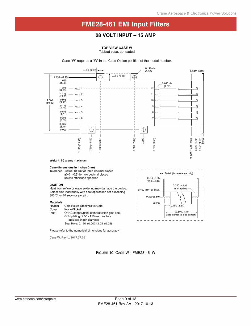
Weight: 86 grams maximum
Case dimensions in inches (mm)Tolerance ±0.005 (0.13) for three decimal places ±0.01 (0.3) for two decimal places unless otherwise specified
CAUTIONHeat from reflow or wave soldering may damage the device. Solder pins individually with heat application not exceeding 300°C for 10 seconds per pin.
MaterialsHeader Cold Rolled Steel/Nickel/GoldCover Kovar/NickelPins #52 alloy/Gold ceramic seal Gold plating of 50 - 150 microinches is included in pin diameter Seal Hole: 0.120 ±0.002 (3.05 ±0.05)
Please refer to the numerical dimensions for accuracy.Case U, Rev L, 2016.11.18
TOP VIEW CASE UFlanged case, short leads
Case “U” does not require a designator in the Case Option position of the model number.
0.25
0 ±0
.010
(6.3
5 ±0
.3)
FIguRe 8: case u - FMe28-461
Crane Aerospace & Electronics Power Solutions
www.craneae.com/interpoint Page 7 of 13
Fme28-461 emi input Filters28 Volt input – 15 amp
FME28-461 Rev AA - 2017.10.13

0.00
0
0.22
0 (5
.59)
0.05
0 (1
.27)
0.40
0 (1
0.16
) max
ref:
0.22
5 (5
.72
(3.45 (87.6))lead center to lead center
0.000
0.120 (3.05)0.250 (6.35)
0.450 (11.43)
0.650 (16.51)
0.850 (21.59)
1.050 (26.67)
1.250 (31.75)1.380 (35.05)
0.00
00.
120
(3.0
5)0.
250
±0.0
10 (6
.35
±0.3
)
2.75
0 (6
9.85
)2.
880
(73.
15)
0.128 dia(3.25)0.040 dia
(1.02)
TOP VIEW CASE VFlanged case, down leaded
Case “V” requires a “V” in the Case Option position of the model number.
1
2
3
4
5
6
12
11
10
9
8
7
Angled cornerindicates pin one.
3.00
5 (7
6.33
) max
Weight: 86 grams maximum
Case dimensions in inches (mm)Tolerance ±0.005 (0.13) for three decimal places ±0.01 (0.3) for two decimal places unless otherwise specified
CAUTIONHeat from reflow or wave soldering may damage the device. Solder pins individually with heat application not exceeding 300°C for 10 seconds per pin.
MaterialsHeader Cold Rolled Steel/Nickel/GoldCover Kovar/NickelPins OFHC copper/gold, compresssion glass seal Gold plating of 50 - 150 microinches Included in pin diameter Seal Hole: 0.120 ±0.002 (3.05 ±0.05)
Please refer to the numerical dimensions for accuracy.Case V, Rev L, 2016.06.28
Seam Seal
1.505 (38.23) max.
0.000
0.220 (5.59)
0.400 (10.16) max.
0.050 typicalinner radius
0.150 (3.81)Lead Detail (for reference only)
(0.250 ±0.05(6.35 ±1.27))
FIguRe 9: case v - FMe28-461v
Crane Aerospace & Electronics Power Solutions
www.craneae.com/interpoint Page 8 of 13
Fme28-461 emi input Filters28 Volt input – 15 amp
FME28-461 Rev AA - 2017.10.13
1
2
3
4
5
6
12
11
10
9
8
7
0.040 dia(1.02)
0.250 (6.35)
0.125 (3.18)
0.375(9.53)
0.575(14.61)
0.775(19.69)
0.975(24.77)
1.175(29.85
1.375(34.93)
1.625(41.28)
2.12
5 (5
3.98
)
0.37
5 (9
.53)
0.140 dia(3.56)
0.00
0
1.75
0 (4
4.45
)
0.000
0.250 (6.35)
1.45
0 (3
6.83
)
0.30
0 (7
.62)
1.750 (44.45)
2.000 (50.80)
TOP VIEW CASE WTabbed case, up-leaded
0.00
0
0.22
0 (5
.59)
0.05
0 (1
.27)
0.40
0 (1
0.16
) max
.
0.000
0.220 (5.59)
0.400 (10.16) max.
(0.84 ±0.05(21.3 ±1.3))
0.150 (3.81)
(2.80 (71.1))(lead center to lead center)
Case “W” requires a “W” in the Case Option position of the model number.
Seam Seal
0.050 typicalinner radius
Lead Detail (for reference only)
Weight: 86 grams maximum
Case dimensions in inches (mm)Tolerance ±0.005 (0.13) for three decimal places ±0.01 (0.3) for two decimal places unless otherwise specified
CAUTIONHeat from reflow or wave soldering may damage the device. Solder pins individually with heat application not exceeding 300°C for 10 seconds per pin.
MaterialsHeader Cold Rolled Steel/Nickel/GoldCover Kovar/NickelPins OFHC copper/gold, compresssion glas seal Gold plating of 50 - 150 microinches Included in pin diameter Seal Hole: 0.120 ±0.002 (3.05 ±0.05)
Please refer to the numerical dimensions for accuracy.
Case W, Rev L, 2017.07.26
FIguRe 10: case w - FMe28-461w
Crane Aerospace & Electronics Power Solutions
www.craneae.com/interpoint Page 9 of 13
Fme28-461 emi input Filters28 Volt input – 15 amp
FME28-461 Rev AA - 2017.10.13

Seam Seal0.250 (6.35)
0.125 (3.18)
0.375(9.53)
0.575(14.61)
0.775(19.69)
0.975(24.77)
1.175(29.85
1.375(34.93)
1.625(41.28)
2.12
5 (5
3.98
)
0.37
5 (9
.53)
0.140 dia(3.56)
0.00
0
1.75
0 (4
4.45
)
0.000
0.250 (6.35)
1.45
0 (3
6.83
)
0.30
0 (7
.62)
1.750 (44.45)
2.000 (50.80)
0.00
0
0.22
0 (5
.59)
0.05
0 (1
.27)
0.40
0 (1
0.16
) max
.
TOP VIEW CASE YTabbed case, straight-leaded
Pin
Leng
th0.
30 ±
0.05
(7.6
±1.
3)
0.040 dia(1.02)
1
2
3
4
5
6
12
11
10
9
8
7
Case “Y” requires a “Y” in the Case Option position of the model number.
Weight: 86 grams maximum
Case dimensions in inches (mm)Tolerance ±0.005 (0.13) for three decimal places ±0.01 (0.3) for two decimal places unless otherwise specified
CAUTIONHeat from reflow or wave soldering may damage the device. Solder pins individually with heat application not exceeding 300°C for 10 seconds per pin.
MaterialsHeader Cold Rolled Steel/Nickel/GoldCover Kovar/NickelPins OFHC copper/gold, compresssion glas seal Gold plating of 50 - 150 microinches Included in pin diameter Seal Hole: 0.120 ±0.002 (3.05 ±0.05)
Please refer to the numerical dimensions for accuracy. Case Y, Rev K, 2016.11.18
0.000
(0.220 (5.59))
0.400 (10.16) max.
0.30 ±0.05(7.6 ±1.3)
(3.10 (78.7))
Lead Detail (for reference only)
FIguRe 11: case y - FMe28-461y
Crane Aerospace & Electronics Power Solutions
www.craneae.com/interpoint Page 10 of 13
Fme28-461 emi input Filters28 Volt input – 15 amp
FME28-461 Rev AA - 2017.10.13

0.250 (6.35)
0.125 (3.18)
0.375(9.53)
0.575(14.61)
0.775(19.69)
0.975(24.77)
1.175(29.85
1.375(34.93)
1.625(41.28)
2.12
5 (5
3.98
)
0.37
5 (9
.53)
0.140 dia(3.56)
0.00
0
1.75
0 (4
4.45
)
0.000
0.250 (6.35)
1.45
0 (3
6.83
)
0.30
0 (7
.62)
1.750 (44.45)
2.000 (50.80)
TOP VIEW CASE ZTabbed case, down-leaded
Case “Z” requires a “Z” in the Case Option position of the model number.
0.00
0
0.22
0 (5
.59)
0.05
0 (1
.27)
0.40
0 (1
0.16
) max
.
0.040 dia(1.02)
1
2
3
4
5
6
12
11
10
9
8
7
Weight: 86 grams maximum
Case dimensions in inches (mm)Tolerance ±0.005 (0.13) for three decimal places ±0.01 (0.3) for two decimal places unless otherwise specified
CAUTIONHeat from reflow or wave soldering may damage the device. Solder pins individually with heat application not exceeding 300°C for 10 seconds per pin.
MaterialsHeader Cold Rolled Steel/Nickel/GoldCover Kovar/NickelPins OFHC copper/gold, compresssion glas seal Gold plating of 50 - 150 microinches Included in pin diameter Seal Hole: 0.120 ±0.002 (3.05 ±0.05)
Please refer to the numerical dimensions for accuracy. Case Z, Rev K, 2016.11.18
Seam Seal
0.000
0.220 (5.59)
0.400 (10.16) max.
(0.36 ±0.05(9.1±0.13))
0.150 (3.81)
(2.80 (71.1))(lead center to lead center)
0.050 typicalinner radius
Lead Detail (for reference only)
FIguRe 12: case z - FMe28-461z
Crane Aerospace & Electronics Power Solutions
www.craneae.com/interpoint Page 11 of 13
Fme28-461 emi input Filters28 Volt input – 15 amp
FME28-461 Rev AA - 2017.10.13

Table is for reference only. See individual Series' datasheets for specific screening.
TABLE 8: ELEMENT EVALUATION HIGH RELIABILITY DC-DC CONVERTERS AND EMI FILTERS /883 (CLASS H)
ELEMENT EVALUATION 1 HIGH RELIABILITY /883 (CLASS H)
QML
CLASS H /883
COMPONENT-LEVEL TEST PERFORMED M/S 2 P 3
Element Electrical n n
Visual n n
Internal Visual n
Final Electrical n n
Wire Bond Evaluation n n
notes1. Element evaluation does not apply to standard and /ES product. 2. M/S = Active components (microcircuit and semiconductor die).3. P = Passive components, Class H element evaluation. Not applicable to
standard and /ES element evaluation.
table 7: eleMent evaluatIOn
Crane Aerospace & Electronics Power Solutions
www.craneae.com/interpoint Page 12 of 13FME28-461 Rev AA - 2017.10.13
Fme28-461 emi input Filters28 Volt input – 15 amp

Table is for reference only. See individual Series' datasheets for specific screening.
TABLE 9: ENVIRONMENTAL SCREENING HIGH RELIABILITY DC-DC CONVERTERS AND EMI FILTERS STANDARD, /ES AND /883 (CLASS H)
ENVIRONMENTAL SCREENING HIGH RELIABILITY STANDARD, /ES AND /883 (CLASS H)
NON-QML 1 CLASS H QML 2
TEST PERFORMEDSTANDARD /ES /883
SX/883CH 3
/883QML 4
pre-cap inspection, method 2017, 2032 n n n n n
temperature cycle (10 times)
Method 1010, Cond. C, -65°C to +150°C, ambient n n n
Method 1010, Cond. B, -55°C to +125°C, ambient n
constant accelerationMethod 2001, 3000 g n n n
Method 2001, 500 g n
pinD, test method 2020, cond. a n n 5 n 5
burn-in method 1015, +125°c case, typical 6
96 hours n
160 hours n n n
Final electrical test, mil-prF-38534, group a, Subgroups 1 through 6, -55°C, +25°C, +125°C case n n n
Subgroups 1 and 4, +25°C case n n
Hermeticity testGross Leak, Cond. C1, fluorocarbon n n n n
Fine Leak, Cond. A2, helium n n n n
Gross Leak, Dip n
Final visual inspection, method 2009 n n n n n
Test methods are referenced to MIL-STD-883 as determined by MIL-PRF-38534.
notes1. Non-QML products may not meet all of the requirements of MIL-PRF-38534.2. All processes are QML qualified and performed by certified operators.3. Class H QML products with no SMD number are marked “CH” per MIL-STD-38534 Rev J, 3.9.5.8.3, Table III.4. Class H QML products have an SMD number 5. Not required by DLA but performed to assure product quality.6. Burn-in temperature designed to bring the case temperature to +125°C minimum.
Burn-in is a powered test.
table 8: envIROnMental scReenIng
Crane Aerospace & Electronics Power Solutions
FME28-461 EMI Input Filters FME28-461 Rev AA - 2017.10.13. This revision supersedes all previous releases. All technical information is believed to be accurate, but no responsibility is assumed for errors or omissions. Crane Electronics, Inc. reserves the right to make changes that do not affect form, fit or function of Class H products or specifications without notice. Interpoint is a registered trademark of Crane Co. and FME Series is a trademark of Crane Electronics, Inc. Copyright © 1999 - 2017 Crane Electronics, Inc. All rights reserved. www.craneae.com/interpoint
Page 13 of 13
Fme28-461 emi input Filters28 Volt input – 15 amp