27.5 Kilowatt Peak Sync. Output Thru VHF-TV Band Full Input to 400 MHz ... 27.5 kilowatt peak sync...
10
VHF Linear Power Amplifier Tube 27.5 Kilowatt Peak Sync. Output Thru VHF-TV Band - 13 dB Gain - High Gain-Bandwidth Products - Efficient Forced-Air Cooling - Full Input to 400 MHz - CERMOLOX® Construction The BURLE 8916 is designed specifically for use in high-gain, high-linearity equipments for VHF-TV and FM service and for communication transmitters to 400 MHz. In VHF-TV service at 223 MHz, the 8916 can deliver up to a full 27.5 kilowatt peak sync output with 6.3 MHz bandwidth and 13 dB gain. Rated for full input for the VHF-TV band and for other service to 400 MHz, the 8916 can be readily circuited for these frequencies. the radiator location avoids restricting the resonant cavity cir- cuits in UHF operation. The 8916 assures high gain-bandwidth products for the full VHF-TV band. In addition, it is well suited for other applications such as single sideband, CW or pulsed RF and modulator service and for FM broadcast service. This data sheet gives application information unique to the BURLE 8916. Important additional information of a general nature, applicable to tubes of this type, is given in the following publications: TP-105 Application Guide for BURLE Power Tubes TP-117 Handling and Operating Considerations when Using BURLE Tetrodes TP-118 Application Guide for Forced Air Cooling BURLE Power Tubes Close attention to the instructions contained therein will assure longer tube life, safer operation, less equipment downtime and fewer tube handling accidents. For specific information or application assistance, contact your nearest BURLE Sales Representative or write Power Tube Marketing, BURLE INDUSTRIES, INC., Lancaster, PA 17601. General Data Electrical Filamentary Cathode, Thoriated-Tungsten Mesh Type: Voltage 1 (AC or DC) . . . . . . . . . . . . . . . . . . . . . . . . . . . . . . . . . . . . . . . . . . . . . . 9.5 10.0 Current: Typical value at 9.5 volts 2 ......................... 147 Maximum value for starting, even momentarily . . . . . . . . . . . . . . . . . . . . . . . . . . . . . . . . . . . . . . . . . . . . . . 300 Cold resistance ............................................... 0.01 Minimum heating time 3 . . . . . . . . . . . . . . . . . . . . . . . . . . . . . . . . . . . . 15 Mu-Factor 4 (Grid No.2 to Grid No.1) . . . . . . . . . . . . . . . . . . . . . . 12.5 Direct Interelectrode Capacitances: Grid No. 1 to plate 5 ............................................................ 0.4 Grid No.1 to filament . . . . . . . . . . . . . . . . . . . . . . . . . . . . . . . . . . ......... 100 Plate to filament 5 .............................................................. 0.15 Grid No.1 to grid No.2 . . . . . . . . . . . . . . . . . . . . . . . . . . . . . . . . . . . . . . . . . . . . 92 Grid No.2 to plate .......................................... 17.2 Grid No.2 to filament 6 .................................................. 4.0 A A ohm S max. pF pF max. pF pF pF max. pF Mechanical Operating Attitude .......................................... Vertical, either end up Overall Length (Max.) ............................................ 180.3 mm (7.10 in) Greatest Diameter (Max.) .................................... 212.1 mm (8.349 in) Socket .......................................................... CD 89-094 7 or equivalent Chimney .............................................................. 9224 7 or equivalent Radiator.. .............................................................. Integral part of tube Weight (Approx.) .......................................................... 10.0 kg (22 Ibs) Thermal Seal Temperature 8 .............................................................. 250 max. °C (Plate, Grid No.2, Grid No.1, Cathode-Filament, and Filament) Plate-Core Temperature 8,9 . . . . . . . . . . . . . . . . . . . . . . . . . . . . 250 max. °C
Transcript of 27.5 Kilowatt Peak Sync. Output Thru VHF-TV Band Full Input to 400 MHz ... 27.5 kilowatt peak sync...

VHF Linear Power Amplifier Tube27.5 Kilowatt Peak Sync. Output Thru VHF-TV Band
- 13 dB Gain- High Gain-Bandwidth Products- Efficient Forced-Air Cooling- Full Input to 400 MHz- CERMOLOX® Construction
The BURLE 8916 is designed specifically for use in high-gain,high-linearity equipments for VHF-TV and FM service and forcommunication transmitters to 400 MHz.
In VHF-TV service at 223 MHz, the 8916 can deliver up to a full27.5 kilowatt peak sync output with 6.3 MHz bandwidth and 13dB gain.
Rated for full input for the VHF-TV band and for other service to400 MHz, the 8916 can be readily circuited for these frequencies.
the radiator location avoids restricting the resonant cavity cir-cuits in UHF operation. The 8916 assures high gain-bandwidthproducts for the full VHF-TV band. In addition, it is well suited forother applications such as single sideband, CW or pulsed RFand modulator service and for FM broadcast service.
This data sheet gives application information unique to theBURLE 8916. Important additional information of a generalnature, applicable to tubes of this type, is given in the followingpublications:
TP-105 Application Guide for BURLE Power TubesTP-117 Handling and Operating Considerations when Using
BURLE TetrodesTP-118 Application Guide for Forced Air Cooling BURLE Power
Tubes
Close attention to the instructions contained therein will assurelonger tube life, safer operation, less equipment downtime andfewer tube handling accidents.
For specific information or application assistance, contact yournearest BURLE Sales Representative or write Power TubeMarketing, BURLE INDUSTRIES, INC., Lancaster, PA 17601.
General DataElectricalFilamentary Cathode, Thoriated-Tungsten Mesh Type:
Voltage1 (AC or DC) . . . . . . . . . . . . . . . . . . . . . . . . . . . . . . . . . . . . . . . . . . . . . . 9.510.0
Current:Typical value at 9.5 volts2 ......................... 147Maximum value for starting,even momentarily . . . . . . . . . . . . . . . . . . . . . . . . . . . . . . . . . . . . . . . . . . . . . . 300
Cold resistance ............................................... 0.01Minimum heating time3 . . . . . . . . . . . . . . . . . . . . . . . . . . . . . . . . . . . . 15
Mu-Factor4 (Grid No.2 to Grid No.1) . . . . . . . . . . . . . . . . . . . . . . 12.5Direct Interelectrode Capacitances:
Grid No. 1 to plate5 ............................................................ 0.4Grid No.1 to filament . . . . . . . . . . . . . . . . . . . . . . . . . . . . . . . . . . ......... 100Plate to filament5 .............................................................. 0.15Grid No.1 to grid No.2 . . . . . . . . . . . . . . . . . . . . . . . . . . . . . . . . . . . . . . . . . . . . 92Grid No.2 to plate .......................................... 17.2Grid No.2 to filament6 .................................................. 4.0
A
Aohm
S
m a x . p FpF
m a x . p FpFpF
m a x . p F
MechanicalOperating Attitude .......................................... Vertical, either end upOverall Length (Max.) ............................................ 180.3 mm (7.10 in)Greatest Diameter (Max.) .................................... 212.1 mm (8.349 in)Socket .......................................................... CD 89-0947 or equivalentChimney .............................................................. 92247 or equivalentRadiator.. .............................................................. Integral part of tubeWeight (Approx.) .......................................................... 10.0 kg (22 Ibs)
ThermalSeal Temperature8 .............................................................. 250 max. °C(Plate, Grid No.2, Grid No.1, Cathode-Filament, and Filament)Plate-Core Temperature8,9 . . . . . . . . . . . . . . . . . . . . . . . . . . . . 250 max. °C

RF Power AmplifierClass B Television Service10
Synchronizing-level conditions per tube unless otherwise specified.Maximum CCS Ratings, Absolute-Maximum ValuesDC Plate Voltage11 . . . . . . . . . . . . . . . . . . . . . . . . . . . . . . . . . . . . . . . . . . . . . . . . . . . . . . . . . . . . . . . . . . . . . . . .13,000 VDC Grid-No.2 Voltage12 . . . . . . . . . . . . . . . . . . . . . . . . . . . . . . . . . . . . . . . . . . . . . . . . . . . . . . . . . . . . . . . .2,000 VDC Grid-No.1 Voltage14 . . . . . . . . . . . . . . . . . . . . . . . . . . . . . . . . . . . . . . . . . . . . . . . . . . . . . . . . . . . . . . . . . .-600 VDC Plate Current ............................................................... 7.0 AGrid-No.2 Input . . . . . . . . . . . . . . . . . . . . . . . . . . . . . . . . . . . . . . . . . . . . . . . . . . . . . . . . . . . . . . . .250 WGrid-No. 1 Input .............................................................. 150 WPlate Dissipation . . . . . . . . . . . . . . . . . . . . . . . . . . . . . . . . . . . . . . . . . . . . . . . . . . . .See Notes 9 & 13
Typical CCS OperationIn a cathode-drive circuit at 216 MHz and a bandwidth of 6.3 MHz15
DC Plate Voltage VDC Grid-No.2 Voltage . . . . . . . . . . . . . . . . . . . . . . . . . . . . . . . . . . . . . . . . . . . . . . . . . . . .1,000 VDC Grid-No.1 Voltage17 . . . . . . . . . . . . . . . . . . . . . . . . . . . . . . . . . . . . . . . . . . . . . . . . . . . . . . . . . . . . . . . . . . . .-95 VZero Signal DC Plate Current . . . . . . . . . . . . . . . . . . . . . . . . . . . . . . . . . . . . 1.25 AEffective RF Load Resistance . . . . . . . . . . . . . . . . . . . . . . . . . . . . . . . . . . . . . . . . . . 670 ohmsDC Plate Current:
Synchronizing level . . . . . . . . . . . . . . . . . . . . . . . . . . . . . . . . . . . . . . . . . . . . . . . . . . . . . .5.85Blanking level ................................................. 4.50
DC Grid-No.2 Current:Synchronizing level . . . . . . . . . . . . . . . . . . . . . . . . . . . . . . . . . . . . . . . . . . . . . . . . . . . . . . 170Blanking level . . . . . . . . . . . . . . . . . . . . . . . . . . . . . . . . . . . . . . . 25
DC Grid-No.1 Current:Synchronizing level ................................................. 900Blanking level ................................................ 320
Input Circuit Efficiency (Approx.) . . . . . . . . . . . . . . . . . . ........... 95Driver Power Output:
Synchronizing level . . . . . . . . . . . . . . . . . . . . . . . . . . . . . . . . . . . . . . . . . . . . . . . . . . . .1,130Blanking level ............................................................... 620
Output Circuit Efficiency (Approx.) .......................... 95Useful Power Output:
Synchronizing level . . . . . . . . . . . . . . . . . . . . . . . . . . . . . . . . . . . . . . . . . . . . . . . . . .27,500Blanking level .................................................. 15,500
RF Power AmplifierClass B, FM Telephony10
Class B, TelegraphyMaximum CCS Ratings, Absolute-Maximum ValuesDC Plate Voltage 11 . . . . . . . . . . . . . . . . . . . . . . . . . . . . . . . . . . . . . . . . . . . . . . . . . . . . . . . . . . . . . . . . . . . . . . . .13,000DC Grid-No.2 Voltage12 . . . . . . . . . . . . . . . . . . . . . . . . . . . . . . . . . . . . . . . . . . . . . . . . . . . . . . . . . . . . . . . .2,000DC Grid-No.1 Voltage ............................................ -600DC Plate Current . . . . . . . . . . . . . . . . . . . . . . . . . . . . . . . . . . . . . . . . . . . . . . . . . . . . . . . . . . . . . . . .6.0DC Grid-No.2 Input . . . . . . . . . . . . . . . . . . . . . . . . . . . . . . . . . . . . . . . . . . . . . . . . . . . . . . . . . .250DC Grid-No.1 Input . . . . . . . . . . . . . . . . . . . . . . . . . . . . . . . . . . . . . . . . . . . . . . . . . . . . . . . . . .150
AA
mAmA
mAmA
%
WW%
WW
VVVA
WW
Plate Dissipation ............................................. See Notes 9 & 13
Typical, Grid-Driven, Class B, FM Telephony19
DC Plate Voltage .......................................................... 12,000DC Grid-No.2 Voltage .................................................... 1,300DC Grid-No.1 Voltage17 .................................................................. -200Zero Signal DC Plate Current .......................................... 250Effective RF Load Resistance ........................................ 1,280DC Plate Current ................................................................ 4.1DC Grid-No.2 Current ........................................................ 20DC Grid-No.1 Current ...................................................... 100Grid Loading Resistance .................................................. 750Driver Power Output20.. ........................................................................ 60Useful Power Output .......................................................... 30
VVV
mAohms
AmAmA
ohmsW
kW
Typical, Grid-Driven, Class B, CCS Telegraphy7.0 MHz
DC Plate Voltage .......................................................... 12,000 VDC Grid-No.2 Voltage .................................................... 1,300 VDC Grid-No.1 Voltage17 .................................................................. -200 VZero Signal DC Plate Current.. .......................................... 250 mAEffective RF Load Resistance.. ...................................... 1,280 ohmsDC Plate Current ................................................................ 4.7 ADC Grid-No.2 Current .......................................................... 90 mADC Grid-No.1 Current ........................................................ 200 mAGrid Loading Resistance .................................................. 750 ohmsDriver Power Output20 ...................................................................... 100 WUseful Power Output.. .......................................................... 40 kW
1.
2.
3.
Measured at the tube terminals. For accurate data the ac filamentvoltage should be measured using an accurate RMS type metersuch as an iron-vane or thermocouple type meter. The dc voltageshould be measured using a high input impedance type meter.For high-current, low-voltage filaments such as are used in the8916, it is recommended that the filament current be monitoredsince very small changes in resistance can produce misleadingchanges in voltage. For maximum life, the filament power shouldbe regulated at the lowest value that will give stable performance.For those applications where hum is a critical consideration, dcfilament or hum-bucking circuits are recommended.The characteristic range of current at 9.5 volts is from 136 to 156amperes. It is recommended that an additional seven amperes beavailable to allow for the normal reduction of filament resistancewith life. Thus the filament supply should be designed for a meanvalue of 163 amperes at 9.5 volts.With special surge-limiting precautions in the filament circuit, thewarm-up time may be reduced to three seconds, The sequencefor applying voltage is as follows:
FilamentBiasPlateScreenRF Drive
4. For plate voltage = 2000 V, grid-No.2 voltage = 1250 V, and platecurrent = 15 A.
5. With external flat metal shield 8” (200 mm) in diameter having acenter hole 3” (76 mm) in diameter. Shield is located in plane ofthe grid-No.2 terminal, perpendicular to the tube axis, and isconnected to grid No.2.
6. With external flat metal shield 8” (200 mm) in diameter having acenter hole 2-3/8” (60 mm) in diameter. Shield is located in planeof the gird-No.1 terminal, perpendicular to the tube axis, and isconnected to grid No.1.
7.
8.9.
As manufactured by: Jettron Products Inc., 56 Route Ten,Hanover, N.J. 07936See Dimensional Outline for Temperature Measurement Points.The value of 250 °C is the average of three readings taken 120°apart around the top of the anode core. No one reading mayexceed 275 °C.
11. See TP-105.The maximum voltage ratings must be modified for operation ataltitudes higher than sea level and for temperatures in excess of20° C in accordance with the curves of Figure 2.The maximum fault energy that can be dissipated within the tubeis approximately 100 joules. Therefore, the energy available for ahigh-voltage arc or fault must be limited to this value by means ofcurrent limiting resistors or fault-protection circuitry. This is espe-cially important in pulse service where high, stored energy and
- 2 -

1213
1415.
large capacitors are used. In typical 25 kW TV transmitters, theseries resistors used are:
plate = 10 ohmsscreen = 30 to 50 ohmsgrid = 50 ohms
For additional information see TP-105 “Application Guide forBURLE Power Tubes”.See TP-105.Permitted plate dissipation is a function of cooling. For specificratings see Forced Air Cooling information in this data sheet.See TP-105.The bandwidth of 6.3 MHz is calculated at the -0.72 dB powerpoints of a double tuned output circuit using two times the tube
Obtained from a fixed supply with an internal impedance of 710ohms to provide necessary increase in bias at crest of modulatingsignal.
17. Adjust for specified zero-signal dc plate current.18. Drive power output represents circuit losses and is the actual
power measured at the input to the grid-No.1 circuit. The actualpower required depends on the operating frequency and thecircuits used. The tube driving power is approximately zero watts.
19. Measured at 7.0 MHz.20. Driver power output represents circuit losses in the driver output
circuit and the grid input circuit in addition to the power necessaryto drive the tube.
Protection CircuitsProtection circuits serve a threefold purpose: safety of person-nel, protection of the tube in the event of abnormal circuitoperation, and protection of the tube circuits in the event ofabnormal tube operation.Power tubes require mechanical protective devices such asinterlocks, relays, and circuit breakers. Circuit breakers alonemay not provide adequate protection in certain power-tubecircuits when the power-supply filter, modulator, or pulse-form-ing network stores much energy. Additional protection may beachieved by the use of high-speed electronic circuits to bypassthe fault current until mechanical circuit breakers are opened.These circuits may employ a control gas tube, such as athyratron or ignitron, depending on the amount of energy to behandled.Operating voltages applied to this device present a shockhazard and appropriate precautions should be taken. Greatcare should be taken during the adjustment of circuits. The tubeand its associated apparatus, especially all parts which may beat high potential above ground, should be housed in a protec-tive enclosure. The protective housing should be designed withinterlocks so that personnel can not possibly come in contactwith any high-potential point in the electrical system. Theinterlock devices should function to break the primary circuit ofthe high-voltage supplies and discharge high-voltage capaci-tors when any gate or door on the protective housing is opened,and should prevent the closing of this primary circuit until thedoor is again locked.
A time-delay relay should be provided in the plate-supply circuitto delay application of plate voltage until the filament hasreached normal operating temperature.An interlocking relay system should be provided to preventapplication of plate voltage prior to the application of sufficient
bias otherwise, with insufficient bias, the resultant highplate current may cause excessive plate dissipation with conse-quent damage to the tube. RF load shorts or other causes ofhigh output VSWR may also cause high dissipations, excessivevoltage gradients, or insulator flashover. The load VSWRshould be monitored and the detected signal used to actuate theinterlock system to remove the plate voltage in less than 10milliseconds after the fault occurs.
Forced AirCoolingCooling air flow is necessary to limit the anode-core and termi-nal-seal temperatures to values that will assure long reliable life.A sufficient quantity of air should be directed past each of theseterminals so that its temperature does not approach the abso-lute-maximum limit. The absolute-maximum temperature ratingfor this tube is 250° C. It is recommended that a safety factor of25° to 50° be applied, to compensate for all probable systemand component variations throughout life.The cooling air must be delivered by the blower through theradiator and at the terminal seals during the application of powerand for a minimum of three minutes after the power has beenremoved.To Cathode-Filament and Filament Terminals - A sufficientquantity of air should be blown directly at these terminals so thattheir temperature does not approach the absolute-maximumlimit of 250° C. A value of at least 60 cfm is recommended.The Cooling Characteristic Curve, 7, indicates the airflow and pressure requirements of a system sufficient to limit thecore temperature to specific values for various levels of plate dis-sipation.Because the cooling capacity of air varies with its density, factorsmust be applied to the air flow to compensate for operation ataltitude or in high temperature environments.During Standby Operation - Cooling air is required when only thefilament voltage is applied to the tube.For further information on forced air cooling, see TP-105 andalso TP-118 “Application Guide for Forced Air Cooling of BURLEPower Tubes”.
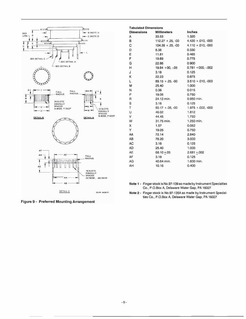
MountingThe preferred mounting arrangement is depicted in Other arrangements, such as cavity-type mounting, for multiple-ring terminal tubes may be constructed using the adjustable orfloating contact rings in the transverse plane.Ready made sockets and chimneys may be obtained in produc-tion quantities from: Jettron Products, Inc., 56 Route Ten,Hanover, N.J. 07986
Socket CD 89-094Chimney 9224
Tube Removal From Socket (Suggested Method)The tube should not be removed from the socket by rocking thetube back and forth. This motion crushes the contact fingersand applies undue force to the internal structure of the tube.
It is recommended that the tube be removed from the socketwith an assembly similar to that shown in Theextractor plate should be constructed with the dimensionsshown in
- 3 -

Figure 1 - Maximum DC Voltage with Respect to Altitude
Figure 2 - Bandwidth Calculation92LM-4427
Figure 3 - Typical Constant Current Tube Characteristics@ Ec2
= 2000 v
- 4 -

- 2 8 0
92LM-4429
-@ EC2

Figure 6 - Electrode Cavity Tuning Characteristics -6-
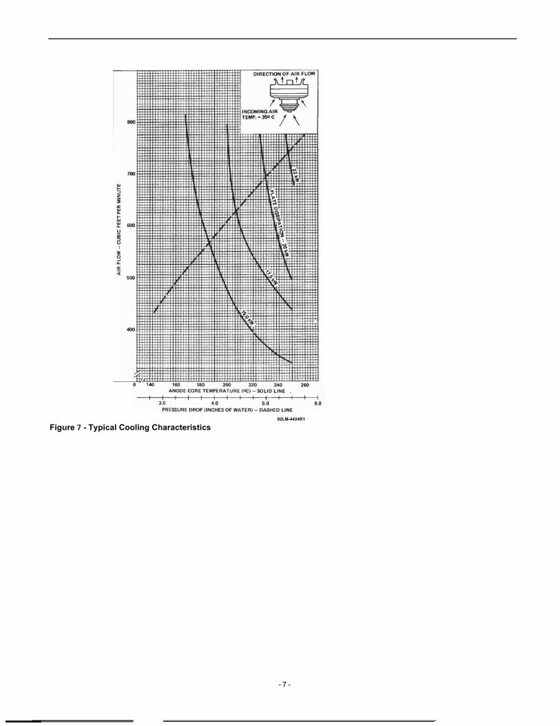
92LM-4424R1
Figure - Typical Cooling Characteristics
- 7 -

Tabulated Dimensions
N
92LM-4425R1
Note 1 - The diameter of each terminal is maintained only over theindicated minimum length of its contact surface.
Note 2 - Keep all stippled regions clear. In general do not allowcontacts to protrude into these annular regions. If specialconnectors are required which may intrude on these re-gions, contact BURLE Power Tube Application Engineering,Lancaster, PA 17601.
Note 3 - Tapped 1/4-20 NC x 12.7 mm (0.5”) deep.Note 4 - Plate core temperature measurement point is located on the
plate itself and not at the fins.Note 5 - With the plate terminal and the cathode-filament terminal
used as reference, the other terminals will measure less than1.02 mm (0.040”) total indicator run-out (TIR).
Figure 8 - Dimensional Outline
- 8 -
Tabulated Dimensions
- 9 -

Figure 10 - Tube Removal Assembly
-10-
Tabulated DimensionsDimensions MillimetersA 47.63B 95.25C 28.58D Dia. 60.33E 190.50F 93.65G Dia. 6.53H 101.60J 50.80K 63.50M 127.00N 9.53P 12.70Figure 11 - Extractor Plate
Inches1.8753.7501.1252.3757.5003.6870.2574.0002.0002.5005.0000.3750.500